Article

Static Hand Gesture Recognition Based on Millimeter-Wave Near-Field FMCW-SAR Imaging

1
College of Computer Science & Engineering, Northwest Normal University, Lanzhou 730070, China
2
Gansu Province Internet of Things Engineering Research Centre, Northwest Normal University, Lanzhou 730070, China
*
Author to whom correspondence should be addressed.
These authors contributed equally to this work.
Electronics 2023, 12(19), 4013; https://doi.org/10.3390/electronics12194013
Submission received: 18 August 2023 / Revised: 20 September 2023 / Accepted: 21 September 2023 / Published: 23 September 2023

Abstract

:
To address the limitations of wireless sensing in static gesture recognition and the issues of Computer Vision’s dependence on lighting conditions, we propose a method that utilizes millimeter-wave near-field SAR (Synthetic Aperture Radar) imaging for static gesture recognition. First, a millimeter-wave near-field SAR imaging system is used to scan the defined static gestures to obtain data. Then, based on the distance plane, the three-dimensional gesture is divided into multiple two-dimensional planes, constructing an imaging dataset. Finally, an HOG (Histogram of Oriented Gradients) is used to extract features from the imaging results, PCA (Principal Component Analysis) is applied for feature dimensionality reduction, and RF (Random Forest) performs classification. Experimental verification shows that the proposed method achieves an average recognition precision of 97% in unobstructed situations and 93% in obstructed situations, providing an effective means for wireless-sensing-based static gesture recognition.

1. Introduction

As an important means of interaction, gestures have been widely applied. Deaf-mute people use sign language based on gestures to communicate with others. Traffic police use hand signals to convey traffic instructions to drivers. Animal trainers use specialized gestures to give commands to animals. In addition to human-to-human and human-to-animal interactions, gestures are also an important means of HCI (Human–Computer Interaction). Currently, smart home appliances such as intelligent speakers and smart lamps have begun to use gesture recognition technology. With the emergence of various somatosensory games, gesture recognition technology is increasingly being applied in the field of electronic games. VR (Virtual Reality) and AR (Augmented Reality) also use gestures as the main means of interaction. The application of gesture recognition in the field of HCI greatly improves interaction efficiency, freeing hands from the operation of devices such as keyboard, mice and handles, making interaction more convenient and faster. Therefore, gesture recognition has high research value and broad research prospects.
Early gesture recognition was achieved utilizing wearable devices. The authors of [1] embedded three-axis accelerometers and gyroscopes into wearable smart devices, obtaining a large amount of hand movement data and achieving continuous gesture recognition. The authors of [2] proposed a gesture recognition method based on three-channel electromyography sensors, wrapping an infrared device around the arm and automatically detecting the start and end points of significant gesture fragments by detecting the intersection points and their moving average curves of electromyography signals. The authors of [3] proposed a gesture recognition method based on optical tagging, which installed a small camera and projector on a hat and placed a ring tag on the finger to form a wearable gesture interface, allowing users to interact with projection information using gestures. Wearable-device-based gesture recognition methods have the drawbacks of inconvenient use and expensive prices, making them difficult to promote. Therefore, contactless gesture recognition methods have begun to gain attention, among which CV (Computer Vision)-based gesture recognition methods have gradually become a research hotspot. The authors of [4] proposed a gesture segmentation and feature extraction method for static gestures under a simple background using camera-captured gesture images and achieved classification using SVM (Support Vector Machine). The authors of [5] proposed an attention mechanism and feature fusion method for improving CNN’s recognition accuracy of static gestures, using camera-captured static gesture data. The authors of [6] introduced various static gesture classification methods based on Computer Vision. The authors of [7] developed a visual recognition system that combined RGB (RGB color mode) and depth descriptors to classify gestures. The authors of [8] constructed a robust finger-part-based gesture recognition system using a Kinect sensor. Moreover, many studies mentioned in [9,10,11,12] also achieved considerable recognition accuracy using CV-based gesture recognition. It can be seen that there has been a great deal of research on contactless gesture recognition based on Computer Vision, and significant progress has been made. However, Computer Vision has the drawbacks of lighting condition dependence and privacy invasion, limiting its usage. To address these issues, contactless gesture recognition based on wireless sensing has begun to attract researchers’ attention.
There have been many studies on gesture recognition based on wireless sensing, which have been based on different frequency bands and modulation techniques. The authors of [13] designed a segmentation algorithm based on wavelet analysis and short-time energy, utilizing fluctuations in Wi-Fi signal CSI (Channel State Information) caused by hand movements, to achieve gesture recognition. Similarly, the authors of [14] achieved fine-grained dynamic gesture recognition using CSI. The authors of [15] proposed a gesture recognition method for IR-UWB (Impulse Radio Ultra-Wideband) radar based on GoogLeNet, achieving high-precision gesture recognition. The authors of [16] introduced common methods using millimeter-wave radar for dynamic gesture recognition, including data processing, feature extraction and classification. The authors of [17] achieved real-time continuous gesture recognition using 24 GHz FMCW (Frequency Modulated Continuous Wave) radar, and the authors of [18] achieved dynamic gesture recognition for multiple hands using 77 GHz FMCW radar.
At present, existing research on gesture recognition has encountered various challenges, such as the inconvenience and high cost of wearable devices. Although Computer Vision can recognize both dynamic and static gestures, it can be limited by lighting conditions and can easily expose a user’s privacy. Traditional wireless sensing methods mostly focus on the recognition of dynamic gestures, but they lack effective methods for recognizing static gestures. This is because traditional wireless sensing methods rely on the Doppler shift to provide relative velocity information for gestures, and they do not provide the spatial features required to distinguish static gestures. Therefore, there is still a great deal of research space and value for wireless-sensing-based static gesture recognition methods.
In recent years, SAR imaging has gradually transitioned from far-field to near-field applications with the popularization of commercial small FMCW millimeter-wave radars. Millimeter-wave near-field SAR imaging is not limited by lighting conditions, has the ability to penetrate and is capable of depicting the contours of objects. These features make it expand the boundaries of wireless sensing, providing a way to realize “wireless vision”. The contours obtained from the imaging can be used as features for recognition.
Based on this research status, we propose a static gesture recognition method based on millimeter-wave near-field FMCW-SAR imaging, and the specific contributions are as follows.
  • We built a millimeter-wave near-field SAR imaging system. The system was deployed to perform static gesture imaging, and the resulting images were utilized as features to accomplish static gesture recognition. In comparison to cameras, the millimeter-wave imaging system is not bound by lighting conditions and can effectively scan static gestures in dark environments.
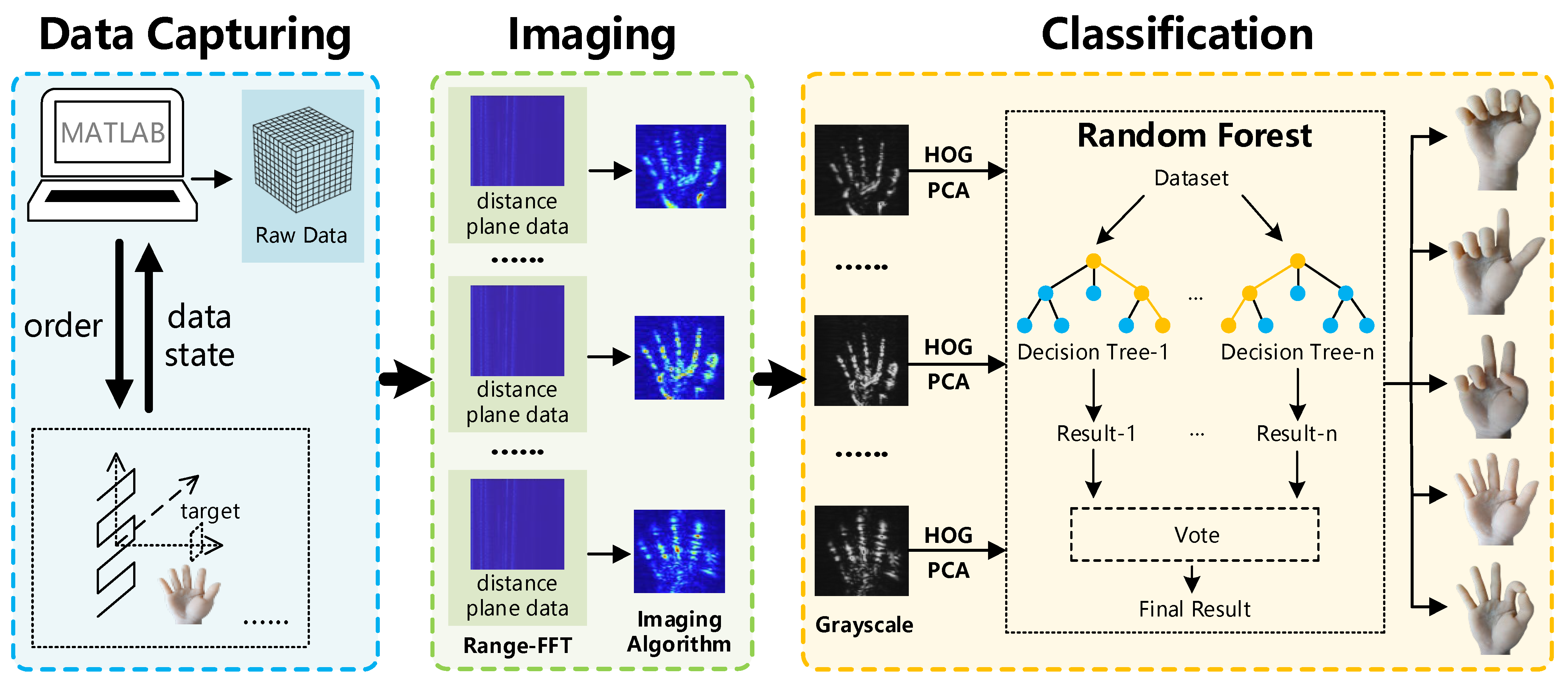
  • We present a method for constructing a dataset of static gesture images. The dataset was generated by using different imaging algorithms to process different static gestures at every distance plane. A classification approach based on HOG–PCA–RF is proposed for this dataset, where HOG was utilized for image feature extraction, followed by dimensionality reduction using PCA and ultimately classification using Random Forest.
  • The system built by us captured the data of five common static gestures and produced images that could approximately reproduce the contours of the gestures. The classification results demonstrate that the proposed method achieved satisfactory recognition precision.
This article consists of five sections. Section 2 mainly introduces the related works on wireless-sensing-based gesture recognition. Section 3 mainly introduces the structure, workflow and specific methods of the method proposed in this article. Section 4 mainly introduces the hardware equipment, parameter settings and experimental results of the proposed method. Section 5 provides a summary of the entire article and gives an outlook on future work.

2. Related Work

Currently, wireless-sensing-based gesture recognition methods mainly focus on dynamic gestures, as dynamic gestures can cause interference in signals and make it easier to extract related features, such as Doppler. For static gestures, it is difficult to extract meaningful features due to the ability to affect the magnitude, phase or other properties of the signal slightly; thus, there is less related work in this area. In this section, we divide the discussion into two parts: dynamic gesture recognition based on wireless sensing and static gesture recognition based on wireless sensing, to introduce related research.

2.1. Dynamic Hand Gesture Recognition Based on Wireless Sensing

The authors of [19] designed a deep spatio-temporal gesture recognition method based on Wi-Fi signals, which segments continuous gestures using a time series differencing algorithm and achieved the goal of dynamic gesture recognition. The authors of [20] proposed a two-stage radio frequency algorithm for dynamic gesture classification by segmenting continuous Wi-Fi packets into gesture instances based on time stamps attached to CSI values. The authors of [21] collected data using millimeter-wave radar and extracted three scene-independent gesture features, namely the distance–time spectrum, distance–Doppler spectrum and distance–angle spectrum. They fused different gesture features using 3D CNN to achieve cross-domain dynamic gesture recognition. The authors of [22] designed a driver-assistant dynamic gesture recognition system using micro-Doppler features obtained using 77 GHz FMCW radar. The authors of [23] proposed a robust dynamic gesture recognition method based on a self-attention time series neural network, which maintained high precision under random dynamic disturbances.

2.2. Static Hand Gesture Recognition Based on Wireless Sensing

The authors of [24] constructed a sensor for gesture recognition using ultra-wideband pulse signals reflected by the hand. They identified static gestures by analyzing singular points of the user’s hand-reflected waveform. The authors of [25] imaged some static gestures using acoustic imaging methods, but the resolution was low. The authors of [26] attempted to image static gestures using millimeter-wave near-field FMCW-SAR imaging. However, due to the insufficient reflectivity of human hands, the imaging effect was too poor to restore gesture contours. Therefore, the authors changed the imaging model to an aluminum-made gesture model and used the results as “sterile” data to improve the accuracy of static gesture recognition. The above research indicates that there has been little research on wireless-sensing-based static gesture recognition, and the results have been unsatisfactory. However, Refs. [27,28] provide new ideas. The authors of [27] used millimeter-wave imaging to image apples, and although they could not restore the contours of the apples, they used the imaging results as features to finally distinguish between healthy and damaged apples. The authors of [28] imaged faces, and although they could not restore the contours of the faces, they used the imaging results as features to achieve the registration of different users’ biometric security information.
Based on what is mentioned above, millimeter-wave imaging can be used for static gesture imaging. The results obtained can be used as features for classification. This can effectively compensate for the shortcomings of static gesture recognition in the field of wireless sensing.

3. System Design

This section is divided into four parts. The first part introduces the overall process of the system, which includes three stages. The second part specifically describes the data capturing stage of the process, with a focus on the original data acquisition method of near-field MIMO-SAR. The third part describes the gesture imaging stage of the process, in which four imaging algorithms are used to construct the imaging dataset. The fourth part describes the gesture classification stage of the process.

3.1. System Overview

The system process diagram, as shown in Figure 1, is divided into three stages. First, in the data capturing stage, the millimeter-wave near-field FMCW-SAR imaging system is used in MIMO (Multiple Input Multiple Output) mode to scan each static gesture and complete the original data acquisition. Second, in the gesture imaging stage, the distance plane is first partitioned, and for each distance plane, four imaging algorithms are used to process the data and obtain four imaging results. Then, all distance planes data are integrated to construct the imaging dataset of static gestures. Finally, in the gesture classification stage, the imaging dataset is used as the input. The HOG is used to obtain the feature descriptor, followed by dimensionality reduction using PCA and classification using RF. The classification result is then output.

3.2. Data Capturing

In order to capture data, we constructed a millimeter-wave near-field FMCW-SAR imaging system, and the data capturing method of this system is shown in Figure 2. Based on SAR, this system uses the motion of the millimeter-wave radar to form a virtual array that is equivalent to a real array. Signals are transmitted and received at each spatial sampling point, and the original radar cube data are finally obtained. The system uses a horizontal-then-vertical motion method. To reduce errors caused by mechanical vibration, this system adopts discrete sampling, meaning that signals are transmitted and received when the radar is stationary and stopped when the radar is in motion. In order to simplify the imaging algorithm, we use the EPC (Equivalent Phase Center) [29] principle to make each transmitting and receiving pair equivalent to a full-duplex antenna positioned in the middle of the transmitting and receiving pair.
Furthermore, in order to improve radar utilization and enhance data capturing efficiency, this system adopts MIMO [30] mode instead of simple SISO (Single Input Single Output) [30] mode. According to the EPC principle, the equivalent virtual array of a SISO system has only one full-duplex antenna. As shown in Figure 2, based on the EPC principle, the 2 × 4 linear array in the figure can be equivalent to a virtual linear array with 8 full-duplex antennas. Therefore, the data capturing efficiency of MIMO is higher than that of SISO. Prior to equivalence, the 2 × 4 receiving array has a distance of 2 λ between the two transmitting antennas and a distance of λ / 2 between the four receiving antennas. According to the EPC principle, the distance between the full-duplex antennas in the equivalent virtual array is λ / 4 , which satisfies the spatial sampling criteria [29] and does not produce a ghost image.
In Figure 2, the primed coordinate corresponds to the scanning plane, and the unprimed coordinate corresponds to the target plane, with a distance z 0 between the two planes. For the synthesized virtual array shown in Figure 2, D x represents the synthesized horizontal aperture length, D y represents the synthesized vertical aperture length, d x represents the spatial sampling interval in the horizontal direction, and d y represents the spatial sampling interval in the vertical direction. Because the used MIMO array can be equivalent to a virtual array of eight vertically distributed full-duplex antennas, d y is greater than d x .
The radar we used adopts FMCW modulation, and its transmitted chirp signal is as follows [31]:
m ( t ) = A cos 2 π ( f 0 t + K t 2 / 2 ) + φ
where K denotes the frequency change rate of the chirp, and f 0 denotes the start frequency of the chirp. The chirp signal is transmitted, then reflected by the target and finally received. After a time delay τ , the received signal is as follows [31]:
b ( t ) = A cos 2 π ( f 0 ( t τ ) + K ( t τ ) 2 / 2 ) + φ
After the transmitting signal and the receiving signal are mixed, the I-channel IF (Intermediate Frequency) signal is obtained as follows [31]:
r I ( t ) = A cos 2 π ( f b t + f 0 τ K τ 2 / 2 ) , f b = K τ
where f b is the beat frequency. The resulting IQ IF signal is as follows [31]:
r ( t ) = r I ( t ) + j r Q ( t ) = A e j 2 π ( f b t + f 0 τ )
This signal is the data captured at each spatial sampling point in the raw data of Figure 2.
For the three-dimensional raw data, first we use range-FFT (Fast Fourier Transform) to distinguish the data of each distance plane, and we then filter out the two-dimensional data of the target distance plane through pulse compression as the input of the imaging algorithm. The process is as follows [31]:
s ( x , y ) = 0 T r ( x , y , t ) e j 2 π K τ 0 t d t
where K τ 0 represents the IF signal frequency corresponding to the target plane (distance z 0 ), r ( x , y , t ) represents the three-dimensional raw data, and s ( x , y ) represents the two-dimensional data corresponding to the target distance plane.

3.3. Static Hand Gesture Imaging

Upon obtaining data for each distance plane, we select several distance planes surrounding the target. For each distance plane, we use the following four imaging algorithms to obtain four approximate results. Finally, we aggregate the results of all distance planes to complete the construction of the dataset for one static gesture. For each type of static gesture, this process is repeated to complete the construction of the entire dataset.
The first imaging algorithm is BP (Back Projection), which is a spatial domain imaging algorithm with the characteristics of good imaging quality and low execution efficiency. Its formula is as follows:
f ( x , y ) = s ( x , y ) e j 2 k x x 2 + y y 2 + z 0 2 d x d y
The second imaging algorithm is AFT (Analytic Fourier Transform), which is a wavenumber domain (spatial frequency domain) imaging algorithm with the characteristics of high imaging quality and high execution efficiency, and it is not affected by ghost images. Its formula is as follows according to [31]:
f ( x , y ) = F T 2 D 1 F T 2 D [ s ( x , y ) ] e j k z z 0 , k x 2 + k y 2 + k z 2 = 2 k 2
The third imaging algorithm is MF (Matched Filter), which is a wavenumber domain imaging algorithm. Its characteristics include high imaging quality and high execution efficiency. The formula for the MF algorithm is as follows [31,32]:
f ( x , y ) = F T 2 D 1 F T 2 D [ s ( x , y ) ] F T 2 D [ h ( x , y ) ]
where the matched filter is [31]
h ( x , y ) = e j 2 k x 2 + y 2 + z 0 2
In the formula, the relevant parameters are k , which denotes the wavenumber (for spatial frequency, k x , k y , k z represent the x, y, z direction wavenumbers, respectively); f x , y , which represents the reflectivity of the target; and F T 2 D and F T 2 D 1 , which denote the two-dimensional Fourier transform and the two-dimensional inverse Fourier transform, respectively. The fourth imaging algorithm is mmSight, which is a robust imaging algorithm based on AFT (Analytic Fourier Transform), and its specific principle is described in [33].

3.4. Gesture Classification

After obtaining the imaging dataset, classification is carried out using HOG, PCA and Random Forest. First, the feature extraction of the imaging result is conducted by HOG, followed by the dimensionality reduction processing of the obtained features using PCA. Finally, Random Forest is utilized to process the reduced results, completing the classification. The static hand gesture classification algorithm is presented in Algorithm 1.
Algorithm 1: Static Hand Gesture Classification
Input:  gesture   imaging   dataset   r a w D a t a
Output:   gesture   predict   target   p r e T a g
1.    f e a t u r e D a t a H O G r a w D a t a
2.    P C A _ D a t a P C A f e a t u r e D a t a , dim    // dim: dimension
3.   for i = 1:1:epoch
4.       R a n d o m F o r e s t . t r a i n P C A _ D a t a _ t r a i n , t a g
5.   end for
6.     p r e T a g R a n d o m F o r e s t . p r e d i c t P C A _ D a t a _ t e s t
7.   function HOG (H)
8.        H x , y H x , y g a m m a
9.        G x x , y H x + 1 , y H x 1 , y    // x-direction gradient
10.      G y x , y H x , y + 1 H x , y 1    // y-direction gradient
11.      G x , y G x x , y 2 + G y x , y 2    // gradient amplitude
12.      α x , y tan 1 G y x , y / G x x , y    // gradient angle
13.      return   H O G _ d e s c r i p t o r G x , y , α x , y
14.   end function
15.    function   PCA   ( X ,   m )                 / / X = { x 1 , x 2 , , x n }
16.      for i = 1:1:n
17.          x i x i 1 n i = 1 n x i    // centralization
18.      end for
19.       C X X T        // calculate the covariance matrix
20.       λ C λ E = 0      // calculate eigenvalue
21.      for i = 1:1:m
22.          ω i λ i           // obtain feature vector
23.      end for
24.       W = { ω 1 , ω 2 , , ω m }      // obtain projection matrix
25.      return WX
26.   end function
The specific flow of the gesture classification algorithm is shown in Figure 3. The HOG part shows various intermediate results in Algorithm 1, and the Random Forest part shows the classification decision mechanism.
The Histogram of Oriented Gradient feature is a type of feature descriptor used for object detection in Computer Vision and image processing. It constructs features by calculating and counting the gradient direction histogram of local regions in images. As shown in the HOG part of Figure 3, the original images are first converted into grayscale and uniformly compressed to a size of 256 × 256. Then, the horizontal and vertical gradients of the compressed image are computed and converted into gradient magnitude spectra and gradient angle spectra. Finally, the HOG feature descriptor is extracted from these spectra, and the corresponding feature vector is computed. Principal Component Analysis aims to use the idea of dimensionality reduction to transform multiple indicators into a few comprehensive indicators, avoiding the curse of dimensionality and reducing training time. Random Forest is an ensemble learning method that integrates multiple decision trees internally. As shown in Figure 3, Random Forest allows each decision tree to randomly and repeatedly select data and make decisions independently. Using a voting mechanism for the results from all decision trees, the most voted decision is chosen as the final result. If there are multiple decisions with the same number of votes, a random selection approach is used to determine the final result.

4. Experiment and Evaluation

The present section is divided into three parts. The first part introduces the experimental platform used in this article, encompassing the relevant hardware equipment and software environment. The second part outlines the experimental parameter settings, which are further subdivided into FMCW parameter settings and scanning platform parameter settings. The third part presents the experimental results, including static gesture imaging results, as well as classification precision and other metrics.

4.1. Experimental Platform

The experimental platform in this article consists of three parts: the scanning platform, radar platform and host computer, as shown in Figure 4a, with details in Figure 4c. The scanning platform is mainly composed of two sliders, which are used to drive the radar platform to move to different spatial sampling points. The radar platform mainly consists of TI’s IWR1642BOOST development board and the DCA1000EVM data capturing card, which are used for signal transmission and reception at spatial sampling points. The host computer is a high-performance computer with the following configuration: i7-10875H CPU, 16 GB RAM and RTX2060 GPU. A corresponding GUI program is written in MATLAB to set the parameters of the scanning platform and to control the scanning platform and radar platform. TI’s mmWave Studio is used to set the FMCW parameters of the radar and receive commands from the MATLAB (R2022a) GUI program. Python (3.6.3) is used to write and execute the related feature extraction, dimensionality reduction and classification algorithms. Due to the low data capturing efficiency of millimeter-wave near-field SAR imaging systems, we refer to the work performed in [34,35] and use a simulated human hand (shown in Figure 4b) made of silica gel to carry out the experiments.

4.2. Experimental Setup

FMCW Parameters: The FMCW parameters for the radar platform are shown in Table 1. The available frequency range for the IWR1642BOOST is 77~81 GHz, so the start frequency is set at 77 GHz. Among all the parameters, bandwidth is the most important, as a higher value for bandwidth leads to a higher distance resolution and more accurate selection of distance planes. The purpose of setting other parameters is to obtain the maximum possible bandwidth, which is close to 4 GHz.
Scanner Parameters: The parameter settings for the scanning platform are shown in Table 1. As can be inferred from the virtual array part in Figure 2, these parameters are related as follows: D x = n x 1 × d x , D y = n y 1 × d y , D x and D y jointly determine the size of the virtual array and ensure that it can cover the target. The range of z 0 is determined by the thickness of the hand. In this article, two-dimensional imaging is adopted. With a distance partition interval of 0.1 mm, the three-dimensional gesture is divided into multiple distance planes, and then two-dimensional imaging is performed on each distance plane. These can be set in the software platform (Figure 4d). d x can be set as “Horizontal Steps Movement”, d y can be set as “Vertical Steps Movement”, n x can be set as “Horizontal Steps”, and n y can be set as “Vertical Steps”. The calculation formula for the data capturing time is as follows: t d a t a _ c a p = n x × n y × t p e r _ p . t p e r _ p indicates the capturing time required for each spatial sampling point (including mechanical movement), with a size of about 0.9 s. Therefore, according to the data in Table 1, the capturing time of a single gesture is about 31.59 min.

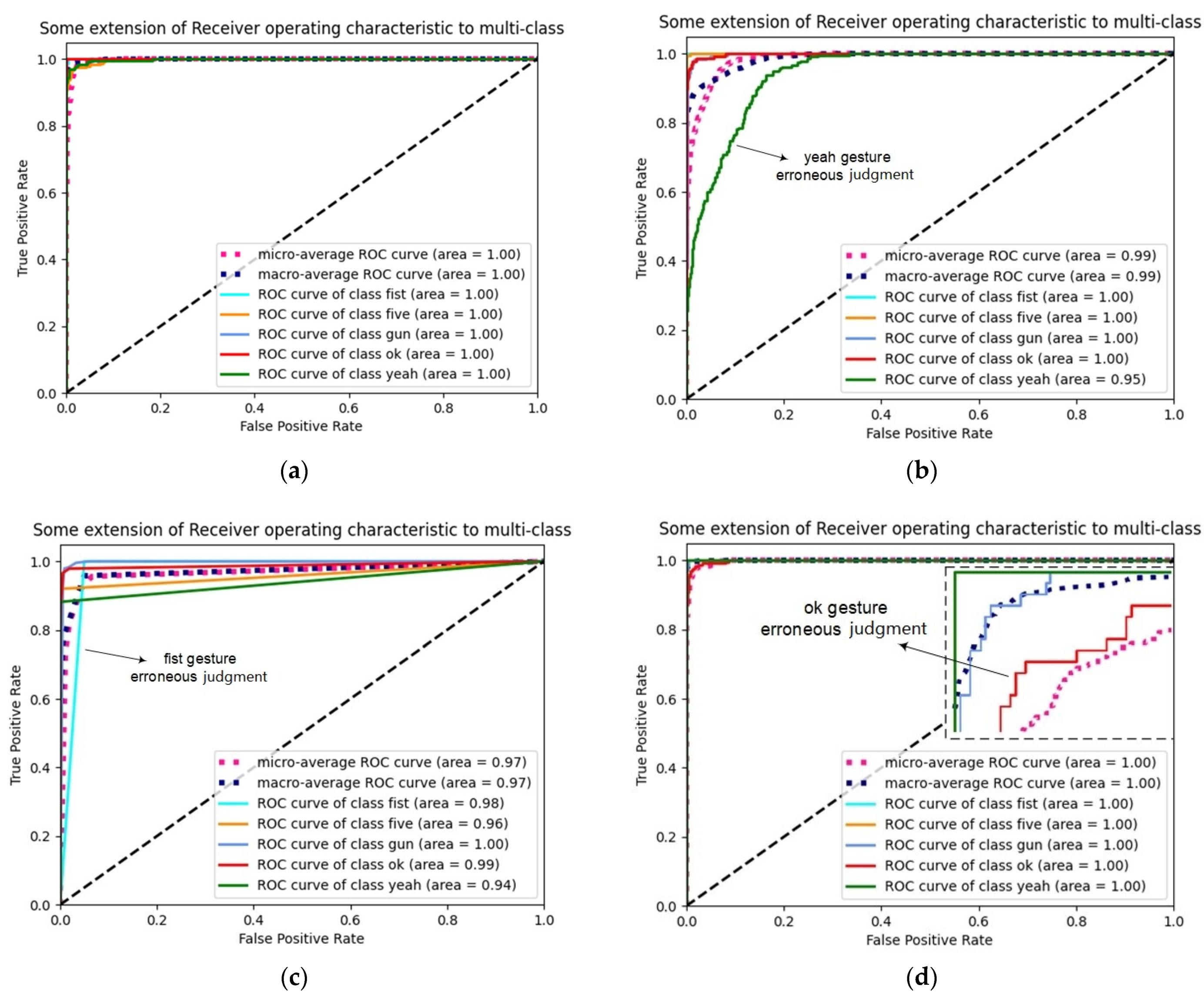
4.3. Experimental Evaluation

We conducted two experiments. The first one is an unobstructed scene, and the second one is an obstructed scene. Figure 5a shows the relative positions of the scanner and the simulated human hand during the experiments. Figure 5b shows that the simulated human hand was entirely obstructed by the cardboard in the obstructed scene.

4.3.1. Imaging Result

The imaging results for the five static hand gestures defined in this article under unobstructed scenarios are shown in Figure 6.
As the distance plane ranges from 350 to 410 mm, not all distance planes’ results can be displayed. Therefore, only the two-dimensional imaging results on the three distance planes corresponding to 360 mm, 380 mm and 400 mm with significant differences are shown (only the results obtained from the AFT algorithm are presented, and the results from other algorithms are similar). From the figure, it can be observed that, although the millimeter-wave imaging results can roughly describe the outline of static hand gestures and cannot convey the detailed information carried by optical images, they can serve as features for classification. Moreover, the imaging results vary with distance, with better imaging quality closer to the hands (such as at 380 mm) and slightly poorer imaging quality farther from the hands (such as at 360 mm and 400 mm).
The imaging results for the five static hand gestures defined in this article under an obstructed scenario (by placing the five hand gestures behind a cardboard box, the simulated human hand is entirely obstructed by the cardboard) are shown in Figure 7.
For the same reason as before, only the two-dimensional imaging results on the three distance planes corresponding to 360 mm, 380 mm and 400 mm are displayed (only showing the results obtained from the AFT algorithm). From the results, it is evident that the millimeter-wave can penetrate the cardboard box and image the target. However, compared with the imaging results in the unobstructed scenario, the imaging quality in the obstructed scenario is slightly inferior. This is because the obstructing object can block or weaken some signals; furthermore, the obstructing object also has a certain reflectivity and can become the most substantial source of noise. As shown in the figure, as the distance to the obstructing object becomes closer (such as at 360 mm), the imaging results become more susceptible to the obstruction and exhibit more noise. Conversely, as the distance from the obstructing object becomes farther (such as at 400 mm), the impact of the obstruction decreases, and the noise in the imaging results also decreases.

4.3.2. Classification Result

In this article, we conducted experimental evaluations using metrics such as precision, average precision, a confusion matrix and an ROC (Receiver Operating Characteristic) curve. Precision denotes the proportion of true positive samples among those predicted as positive. For humans, the result of recognition scenes is deterministic, so high precision is required. Precision is defined as follows:
P r e c i s i o n = T P T P + F P
TPs (true positives) represent the number of true positive samples, which are correctly identified as positive through predictions. FPs (false positives) denote the number of false positive samples, which are incorrectly classified as positive via predictions. The confusion matrix presents the number of instances classified into different categories based on the predicted and actual classes. Each column of the matrix represents the predicted class, with its total count representing the amount of data predicted as belonging to that class. Each row represents the true class, with its total count indicating the number of instances of that class. The ROC curve illustrates the false positive probability under different decision criteria, with better results reflected by a curve that is closer to the upper-left corner. In this article, a confusion matrix and ROC curve were used to evaluate the performance of the classification algorithm. Apart from RF (Random Forest), we also employed SVM (Support Vector Machine), KNN (K-Nearest Neighbor) and GBDT (Gradient Boosted Decision Tree) as comparative classification algorithms. The dataset used in this study contained 9455 images, with 8270 of them allocated to the training set and the remaining 1185 used as the testing set.
The hyperparameter settings for the four classification algorithms are shown in Table 2. Among them, the SVM and KNN parameters are the default settings of sklearn, and GBDT and RF, especially RF, optimize some parameters. To prevent underfitting, we set n_estimators to 100. To avoid overfitting problems caused by large depths, we set max_depth to 7. To avoid the uneven loading of leaf nodes, resulting in wasted resources, we set min_samples_leaf to 3. For GBDT, we increase the number of estimators and decrease the depth, min_samples_leaf. After conducting several experiments, the parameters of RF are set to the optimal values to obtain optimal results. The main significance of the four algorithms is to verify the feasibility of the imaging dataset as a feature, and the results show that the imaging dataset can be used as a feature for static gestures.
  • Unobstructed scene.
In order to verify the basic static gesture recognition function, we conducted routine experiments in unobstructed scenarios, and the resulting confusion matrix is shown in Figure 8. The confusion matrix indicates that Random Forest achieved good results, whereas other methods showed poor detection of certain gestures. SVM had slightly lower precision in recognizing the ok and yeah gestures, KNN had slightly lower precision in recognizing the five and yeah gestures, and GBDT had slightly lower precision in recognizing the gun gesture. The position of the gesture may be a factor affecting misclassification; for example, the GBDT result misclassified the gun gesture as the ok gesture. In addition, as shown in Figure 6, the amplitude intensity of the imaging results varies at different distances, and weak amplitude intensity results are prone to misclassification. For example, the yeah gesture was misclassified as the fist gesture in the KNN and SVM results. Furthermore, the GBDT algorithm used here did not limit the depth of the trees, leading to overfitting.
As shown in Figure 9, the ROC curve was plotted. Both the Random Forest and GBDT methods exhibited good classification performance, whereas SVM had a certain false positive rate for the yeah gesture, and KNN had a certain false positive rate for the fist gesture. The micro (Micro-averaging) and macro (Macro-averaging) reflected the false positive rates of the algorithms for the overall five gestures. It can be seen that the false positive rates of SVM and KNN were relatively high. The average precision rates are shown in Table 3. Random Forest and GBDT achieved good results, whereas SVM and KNN performed relatively poorly.
  • Obstructed scene.
In order to verify the penetration capability of millimeter-wave and facilitate its application in specific scenarios, we conducted experiments by placing a cardboard box as an obstruction between the scanning platform and the simulated hand. The confusion matrix obtained from the experiment is shown in Figure 10.
The confusion matrix indicates that, for all methods tested in the obstructed scenario, there were certain gestures with poor detection. SVM exhibited slightly lower precision in recognizing the gun and yeah gestures, and KNN exhibited slightly lower precision in recognizing the gun and ok gestures. GBDT exhibited slightly lower precision in recognizing the yeah and fist gestures, and Random Forest exhibited slightly lower precision in recognizing the ok gesture. In the obstructed scenario, the position of the gesture can also affect its recognition, leading to misclassification. For example, in the GBDT results, the yeah gesture was misclassified as the ok gesture. Furthermore, as shown in Figure 7, the amplitude intensity of the imaging results varied with different distance planes, which could have caused misclassification for results with weaker intensity. For instance, in the KNN results, the ok gesture was misclassified as the gun gesture.
The ROC curve is shown in Figure 11. Random Forest and GBDT performed well in classification, SVM exhibited a certain false positive rate in recognizing the gun gesture, and KNN exhibited a certain false positive rate in recognizing the ok and gun gestures. The micro and macro reflected the overall false positive rates for the algorithms across all five gestures. The average precision rates are shown in Table 4. Random Forest achieved good recognition performance, and GBDT, SVM and KNN exhibited slightly poorer recognition performance.

5. Conclusions and Discussion

In this article, a method for recognizing static gestures using millimeter-wave imaging is proposed, which addresses the shortcomings in static gesture recognition in the field of wireless sensing. This approach has the advantage of being unaffected by lighting conditions, compared to visual methods such as cameras. The method first utilizes near-field millimeter-wave MIMO-FMCW-SAR imaging to image static gestures and then constructs an imaging dataset based on the distance plane. Finally, feature extraction, dimension reduction and classification are accomplished using the HOG–PCA–RF combination algorithm. Through extensive experimental verification, the proposed method achieved an average recognition precision of 97% in unobstructed scenarios and 93% in obstructed scenarios. However, there are still some limitations in this work, which are discussed below.
  • The data capturing time is long and meets the real-time requirements with difficulty. The data capturing time is about 30 min for one gesture with our platform, and it is hard to keep an experimenter’s hand static from begin to end. This is one of the reasons why we used a simulated human hand to conduct the imaging experiment (another reason: in work performed in [34,35], simulated humans have already been used to conduct imaging experiments). Improvements can be made in two aspects in the future. Regarding the hardware aspect, a radar with more antenna units can be selected, but this increases hardware costs. Regarding the algorithm aspect, techniques such as Compressive Sensing, Deep Learning and Matrix Compensation can be used to reduce spatial sampling points, which can restore under-sampled data to full-sampled data, thereby reducing the capturing time.
  • The lack of consideration for the same type of static gesture from different angles and directions led to low system robustness. In the future, better feature extraction methods can be considered to extract features that are independent of angles and directions, followed by robustness-testing experiments.
  • Due to limitations in data capturing efficiency, experiments had to be conducted using simulated hands. Compared with a real human hand, the material used for a simulated human hand is more ideal, and it has higher reflectivity, thus obtaining better imaging results. It is possible that simulated hands might work better than real hands. Therefore, in the future, experiments can be carried out using human hands when data capturing efficiency improves.
  • The cardboard box experiment shows that, compared to Computer Vision, wireless sensing has the ability to penetrate obstruction and recognize gestures behind it. However, the cardboard box clearly has an effect on the signal. Different materials of the obstruction have different effects on the signal. According to the SAR imaging algorithm, as the reflectivity of the material (such as metal) increases, it becomes more difficult to penetrate; conversely, as reflectivity decreases, it becomes easier to penetrate the material (such as a cardboard box). Therefore, the penetration ability of wireless sensing is limited, which is related to the reflectivity (in other words, the material) of the obstruction. Therefore, depending on the material, it is important to determine the penetration range of millimeter-wave imaging in wireless sensing.
  • This article focuses on the research of static gesture recognition via wireless sensing and does not involve research on dynamic gestures via wireless sensing. How to use wireless sensing to recognize dynamic gestures and static gestures together is a big challenge in the future.

Author Contributions

Conceptualization, R.W. and Z.H.; methodology, R.W.; software, R.W.; validation, R.W.; formal analysis, R.W. and J.P.; investigation, R.W. and J.P.; resources, Z.H. and X.D.; data curation, R.W.; writing—original draft preparation, R.W.; writing—review and editing, R.W. and Z.H.; visualization, R.W. and J.P.; supervision, Z.H.; project administration, Z.H.; funding acquisition, Z.H. All authors have read and agreed to the published version of the manuscript.

Funding

This research was funded by the National Natural Science Foundation of China (Grant 62262061, Grant 62162056), the Gansu Provincial Department of Education: Industry Support Program Project (2022CYZC-12), the Lanzhou City Technology Innovation and Entrepreneurship Talent Project (2021-RC-81, 2020-RC-116), the 2019 Lanzhou City Science and Technology Plan Project (2019-4-44), the Key Research and Development Plan of Gansu Province (Grant 22YF7GA181) and the Gansu Province Small and Medium-sized Enterprise Innovation Fund (Grant 22CX3GA040).

Data Availability Statement

Not applicable.

Acknowledgments

The authors would like to thank the reviewers and editors for their selfless help to improve our manuscript.

Conflicts of Interest

The authors declare no conflict of interest.

References

  1. Gupta, H.P.; Chudgar, H.S.; Mukherjee, S.; Dutta, T.; Sharma, K. A continuous hand gestures recognition technique for human-machine interaction using accelerometer and gyroscope sensors. IEEE Sens. J. 2016, 16, 6425–6432. [Google Scholar] [CrossRef]
  2. Lian, K.Y.; Chiu, C.C.; Hong, Y.J.; Sung, W.T. Wearable armband for real time hand gesture recognition. In Proceedings of the IEEE International Conference on Systems, Man, and Cybernetics (SMC), Banff, AB, Canada, 5–8 October 2017; IEEE: Piscataway, NJ, USA, 2017; pp. 2992–2995. [Google Scholar]
  3. Mistry, P.; Maes, P.; Chang, L. WUW-wear Ur world: A wearable gestural interface. In CHI’09 Extended Abstracts on Human Factors in Computing Systems; Association for Computing Machinery: New York, NY, USA, 2009; pp. 4111–4116. [Google Scholar]
  4. Xu, Y.; Zhou, H. Static gesture recognition based on OpenCV in a simple background. Comput. Sci. 2022, 49 (Suppl. S2), 393–398. [Google Scholar]
  5. Hu, Z.; Zhou, Y.; Shi, B.; He, H. Static gesture recognition algorithm based on attention mechanism and feature fusion. Comput. Eng. 2022, 48, 240–246. [Google Scholar]
  6. Oyedotun, O.K.; Khashman, A. Deep learning in vision-based static hand gesture recognition. Neural Comput. Appl. 2017, 28, 3941–3951. [Google Scholar] [CrossRef]
  7. Ohn-Bar, E.; Trivedi, M.M. Hand gesture recognition in real time for automotive interfaces: A multimodal vision-based approach and evaluations. IEEE Trans. Intell. Transp. Syst. 2014, 15, 2368–2377. [Google Scholar] [CrossRef]
  8. Ren, Z.; Yuan, J.; Meng, J.; Zhang, Z. Robust part-based hand gesture recognition using kinect sensor. IEEE Trans. Multimed. 2013, 15, 1110–1120. [Google Scholar] [CrossRef]
  9. Rogez, G.; Supancic, J.S.; Ramanan, D. Understanding everyday hands in action from RGB-D images. In Proceedings of the IEEE International Conference on Computer Vision, Santiago, Chile, 7–13 December 2015; pp. 3889–3897. [Google Scholar]
  10. Jian, H.E.; Li, J.J.; Cheng, Z.H.; Xin, W.E.; Jia, B.A.; Wang, W.D. Visual gesture recognition technology based on long and short-term memory and deep neural network. J. Graph. 2020, 41, 372–381. [Google Scholar]
  11. Sha, J.; Ma, J.; Mou, H.; Hou, J. Overview of dynamic gesture recognition based on vision. Comput. Sci. Appl. 2020, 10, 990–1001. [Google Scholar]
  12. Wang, L.; Ma, Z.; Tang, X.; Wang, Z.; Zhou, G.; He, S. A gesture recognition method inspired by visual perception for extravehicular activities. Manned Spacefl. 2017, 23, 805–810. [Google Scholar]
  13. Al-Qaness, M.A.A.; Li, F. WiGeR: WiFi-based gesture recognition system. ISPRS Int. J. Geo. Inf. 2016, 5, 92. [Google Scholar] [CrossRef]
  14. Abdelnasser, H.; Harras, K.; Youssef, M. A ubiquitous WiFi-based fine-grained gesture recognition system. IEEE Trans. Mob. Comput. 2018, 18, 2474–2487. [Google Scholar] [CrossRef]
  15. Ahmed, S.; Cho, S.H. Hand gesture recognition using an IR-UWB radar with an inception module-based classifier. Sensors 2020, 20, 564. [Google Scholar] [CrossRef] [PubMed]
  16. Dong, Y.; Qu, W.; Qiu, L. Overview of Research on Millimeter Wave Radar Gesture Recognition. J. Ordnance Equip. Eng. 2021, 42, 119–125. [Google Scholar]
  17. Zhang, Z.; Tian, Z.; Zhou, M. Latern: Dynamic continuous hand gesture recognition using FMCW radar sensor. IEEE Sens. J. 2018, 18, 3278–3289. [Google Scholar] [CrossRef]
  18. Wang, Y.; Wang, D.; Fu, Y.; Yao, D.; Xie, L.; Zhou, M. Multi-Hand Gesture Recognition Using Automotive FMCW Radar Sensor. Remote Sens. 2022, 14, 2374. [Google Scholar] [CrossRef]
  19. Dang, X.; Bai, Y.; Hao, Z.; Liu, G. Wi-GC: A Deep Spatiotemporal Gesture Recognition Method Based on Wi-Fi Signal. Appl. Sci. 2022, 12, 10425. [Google Scholar] [CrossRef]
  20. Zhang, T.; Song, T.; Chen, D.; Zhang, T.; Zhuang, J. WiGrus: A WiFi-based gesture recognition system using software-defined radio. IEEE Access 2019, 7, 131102–131113. [Google Scholar] [CrossRef]
  21. Dang, X.; Wei, K.; Hao, Z.; Ma, Z. Cross-Scene Sign Language Gesture Recognition Based on Frequency-Modulated Continuous Wave Radar. Signals 2022, 3, 875–894. [Google Scholar] [CrossRef]
  22. Wu, Q.; Zhao, D. Dynamic hand gesture recognition using FMCW radar sensor for driving assistance. In Proceedings of the 2018 10th International Conference on Wireless Communications and Signal Processing (WCSP), Hangzhou, China, 18–20 October 2018; IEEE: Piscataway, NJ, USA, 2018; pp. 1–6. [Google Scholar]
  23. Jin, B.; Peng, Y.; Kuang, X.; Zhang, Z.; Lian ZWang, B. Robust Dynamic Hand Gesture Recognition Based on Millimeter Wave Radar Using Atten-TsNN. IEEE Sens. J. 2022, 22, 10861–10869. [Google Scholar] [CrossRef]
  24. Kim, S.Y.; Han, H.G.; Kim, J.W.; Lee, S.; Kim, T.W. A hand gesture recognition sensor using reflected impulses. IEEE Sens. J. 2017, 17, 2975–2976. [Google Scholar] [CrossRef]
  25. Wang, P.; Jiang, R.; Liu, C. Amaging: Acoustic Hand Imaging for Self-adaptive Gesture Recognition. In Proceedings of the IEEE Infocom 2022-IEEE Conference on Computer Communications, London, UK, 2–5 May 2022; IEEE: Piscataway, NJ, USA, 2022; pp. 80–89. [Google Scholar]
  26. Smith, J.W.; Thiagarajan, S.; Willis, R.; Makris, Y.; Torlak, M. Improved static hand gesture classification on deep convolutional neural networks using novel sterile training technique. IEEE Access 2021, 9, 10893–10902. [Google Scholar] [CrossRef]
  27. Zidane, F.; Lanteri, J.; Brochier, L.; Joachimowicz, N.; Roussel, H.; Migliaccio, C. Damaged apple sorting with mmwave imaging and nonlinear support vector machine. IEEE Trans. Antennas Propag. 2020, 68, 8062–8071. [Google Scholar] [CrossRef]
  28. Xu, W.; Song, W.; Liu, J.; Liu, Y.; Cui, X.; Zheng, Y.; Han, J.; Wang, X.; Ren, K. Mask does not matter: Anti-spoofing face authentication using mmWave without on-site registration. In Proceedings of the 28th Annual International Conference on Mobile Computing and Networking, Sydney, Australia, 17–21 October 2022; pp. 310–323. [Google Scholar]
  29. Li, J.; Stoica, P. MIMO Radar Signal Processing; John Wiley & Sons: Hoboken, NJ, USA, 2009. [Google Scholar]
  30. Texas Instruments. MIMO Radar. Available online: https://www.ti.com.cn/cn/lit/an/swra554a/swra554a.pdf (accessed on 1 July 2018).
  31. Yanik, M.E.; Torlak, M. Millimeter-wave near-field imaging with two-dimensional SAR data. In Proceedings of the SRC Techcon, Austin, TX, USA, 16–18 September 2018. [Google Scholar]
  32. Che, L.; Wu, X.; Wang, L.; Du, G.; Jiang, L. Improved algorithm of millimeter wave with complex network and sparse imaging. Appl. Res. Comput. 2022, 39, 604–608. [Google Scholar] [CrossRef]
  33. Hao, Z.; Wang, R.; Dang, X.; Yan, H.; Peng, J. mmSight: A Robust Millimeter-Wave Near-Field SAR Imaging Algorithm. Appl. Sci. 2022, 12, 12085. [Google Scholar] [CrossRef]
  34. Fan, B.; Gao, J.K.; Li, H.J.; Jiang, Z.J.; He, Y. Near-Field 3D SAR Imaging Using a Scanning Linear MIMO Array with Arbitrary Topologies. IEEE Access 2019, 8, 6782–6791. [Google Scholar] [CrossRef]
  35. Sheen, D.; Mcmakin, D.; Hall, T. Near-field three-dimensional radar imaging techniques and applications. Appl. Opt. 2010, 49, E83–E93. [Google Scholar] [CrossRef] [PubMed]
Figure 1. Processing flow.
Electronics 12 04013 g001
Figure 2. SAR data capturing method (red: transmitting antennas; blue: receiving antennas; orange: virtual antennas).
Electronics 12 04013 g002
Figure 3. HOG–PCA–RF method.
Electronics 12 04013 g003
Figure 4. Experimental platform: (a) Experimental device; (b) Simulated human hand; (c) Hardware platform structure; (d) Software platform.
Electronics 12 04013 g004
Figure 5. Experimental scenario: (a) Hand positioning; (b) Simulated human hand entirely obstructed by cardboard.
Electronics 12 04013 g005
Figure 6. Static gesture imaging results in unobstructed scene: (a) Gesture five; (b) Gesture yeah; (c) Gesture gun; (d) Gesture ok; (e) Gesture fist; (f) Five result at 360 mm; (g) Yeah result at 360 mm; (h) Gun result at 360 mm; (i) Ok result at 360 mm; (j) Fist result at 360 mm; (k) Five result at 380 mm; (l) Yeah result at 380 mm; (m) Gun result at 380 mm; (n) Ok result at 380 mm; (o) Fist result at 380 mm; (p) Five result at 400 mm; (q) Yeah result at 400 mm; (r) Gun result at 400 mm; (s) Ok result at 400 mm; (t) Fist result at 400 mm.
Electronics 12 04013 g006
Figure 7. Static gesture imaging results in obstructed scene: (a) Gesture five; (b) Gesture yeah; (c) Gesture gun; (d) Gesture ok; (e) Gesture fist; (f) Five result at 360 mm; (g) Yeah result at 360 mm; (h) Gun result at 360 mm; (i) Ok result at 360 mm; (j) Fist result at 360 mm; (k) Five result at 380 mm; (l) Yeah result at 380 mm; (m) Gun result at 380 mm; (n) Ok result at 380 mm; (o) Fist result at 380 mm; (p) Five result at 400 mm; (q) Yeah result at 400 mm; (r) Gun result at 400 mm; (s) Ok result at 400 mm; (t) Fist result at 400 mm.
Electronics 12 04013 g007
Figure 8. Confusion matrix of unobstructed scene: (a) HOG + PCA + RF; (b) HOG + PCA + SVM; (c) HOG + PCA + KNN; (d) HOG + PCA + GBDT.
Electronics 12 04013 g008
Figure 9. ROC curve of unobstructed scene: (a) HOG + PCA + RF; (b) HOG + PCA + SVM; (c) HOG + PCA + KNN; (d) HOG + PCA + GBDT.
Electronics 12 04013 g009
Figure 10. Confusion matrix of obstructed scene: (a) HOG + PCA + RF; (b) HOG + PCA + SVM; (c) HOG + PCA + KNN; (d) HOG + PCA + GBDT.
Electronics 12 04013 g010
Figure 11. ROC curve of obstructed scene: (a) HOG + PCA + RF; (b) HOG + PCA + SVM; (c) HOG + PCA + KNN; (d) HOG + PCA + GBDT.
Electronics 12 04013 g011
Table 1. Parameter settings.
FMCW ParametersValueScanner ParametersValue
Start Frequency (GHz)77 D x (mm)160
Chirp Slope (MHz/μs)57.115 D y (mm)200
Bandwidth (MHz)3998.05 d x (mm)2
ADC Samples384 d y (mm)8
Sample Rate (ksps)6250 horizontal   sampling   points :   n x 81
vertical   sampling   points :   n y 26
z 0 (mm)350~410
Table 2. Hyperparameter of classification algorithm.
AlgorithmHyperparameter
RFn_estimators = 100, max_depth = 7, min_samples_leaf = 3
SVMC = 1.0, kernel = ‘rbf’, gamma = ‘auto’, probability = False, shrinking = True
KNNn_neighbors = 5, weights = ‘uniform’, algorithm = ‘auto’, leaf_size = 30, p = 2
GBDTn_estimators = 200, max_depth = 3, min_samples_leaf = 1
Table 3. Average precision of unobstructed scene.
MethodAverage Precision
HOG + PCA + Random Forest97.55%
HOG + PCA + SVM85.73%
HOG + PCA + KNN87.08%
HOG + PCA + GBDT95.27%
Table 4. Average precision of obstructed scene.
MethodAverage Precision
HOG + PCA + Random Forest93.41%
HOG + PCA + SVM89.62%
HOG + PCA + KNN88.10%
HOG + PCA + GBDT87.17%
Disclaimer/Publisher’s Note: The statements, opinions and data contained in all publications are solely those of the individual author(s) and contributor(s) and not of MDPI and/or the editor(s). MDPI and/or the editor(s) disclaim responsibility for any injury to people or property resulting from any ideas, methods, instructions or products referred to in the content.

