Abstract
This paper presents the deployment of a hybrid energy harvesting system that combines a wireless energy harvesting (EH) system and a 6 V, 170 mA monocrystalline solar energy derived from the Sun’s rays. The hybrid energy harvesting (HEH) system comprises the rectifier, the solar cell panel, the charging circuit, and the EM4325 embedded RFID tag. This study aims to design an efficient EH system capable of increasing the read range of an active RFID tag. The proposed approach integrates a meandered line radio frequency identification (RFID) tag with an EM4325 IC chip as the receiver antenna. A halfwave doubler RF rectifier circuit is connected to the antenna using a 50 Ω SMA connector to convert the captured RF waves into usable electrical power. A solar energy charging module equipped with a Maximum Power Point Tracking (MPPT) system, a rechargeable lithium-ion battery, and a DC-DC converter is configured to manage and store the harvested energy efficiently. The UHF tag antenna operates at 919 MHz, achieving a peak gain of 3.54 dB. The proposed rectenna achieves a maximum measured harvested power conversion efficiency (PCE) of 55.14% for an input power (Pin) of 15 dBm at a distance of 5.10 cm, while the solar cell panel realizes 3.92 W of power. Experimental results demonstrate the hybrid harvester system’s effectiveness, achieving a PCE of 86.49% at an output voltage (VDC) of 5.35 V. The main advantage of this approach is the creation of a compact hybrid RF and solar EH system by combining the solar cell panel with the antenna, thus enabling multi-functionality.
1. Introduction
In our contemporary and idealistic age, the pursuit of constructing smart cities has spurred technological progress. Various advancements such as fog computing [1], the Internet of Things (IoT) [2], Wireless Sensor Networks (WSNs) [3], Big Data [4], and more have gained prominence to meet the growing demand for these innovations. A common challenge these technologies face is their limited lifespan, which hampers their usability. To address this issue, hybrid energy harvesting has emerged as a promising solution for powering active Radio Frequency Identification (RFID) tags, revolutionizing the field of wireless sensing and communication. Active RFID tags require a continuous power source to maintain their sensing [5], data processing, and wireless transmission functions [6]. Traditional battery-powered tags come with limitations such as finite energy capacity and maintenance requirements. In contrast, hybrid energy harvesting combines multiple energy sources, often including ambient light, radio frequency (RF) signals, and vibrational energy, to create self-sustaining power systems for active RFID tags. This innovation addresses the challenges of battery replacement, extends operational lifetimes [7], and enhances the efficiency of data collection and transmission. Several researches have examined the feasibility of integrating solar energy and RF signals to create energy harvesting systems. Hybrid RF and solar energy harvesting devices have been introduced in prior research [8,9,10]. In this context, this article delves into the intricacies of hybrid energy harvesting techniques, their integration with active RFID technology, and the transformative potential they hold for creating autonomous and environmentally friendly RFID systems. Moreover, The authors in [11,12,13], have discussed the application of wireless energy transfer and harvesting techniques, which are being employed to power the next generation of wireless networks.
Despite the presence of drawbacks that impose constraints on the utilization of current EH methods, introducing hybrid energy harvesting (HEH) systems has emerged as a viable solution to overcome these limitations and improve the overall reliability of energy harvesting. The authors in [14] introduce a hybrid energy harvester designed for the GSM 900 band, combining solar and radio frequency (RF) energy. A study outlined in [15] explores an energy harvesting protocol combining radio frequency (2.4 GHz) energy and thermal energy extraction, providing a unique approach to EH. The proposed methodology incorporates the utilization of a rectenna for radio frequency (RF) energy extraction alongside integrating a thermoelectric generator for capturing human thermal energy. However, it is imperative to acknowledge that successful implementation of this technique necessitates the secure attachment of the device to the human skin, which constitutes a specific requirement. The authors in [16] introduce a custom-built hybrid circuit design to harness energy from both solar and RF sources. The circuit’s primary objective is to optimize the utilization of solar and RF energy utilization, ensuring continuous operation in outdoor low-power applications. In their study [11], the authors introduce a compact rectenna that operates at dual bands (900 and 1800 MHz), intending to improve the RF-to-DC power conversion efficiency (PCE) to harvest ambient RF energy. The experimental findings revealed that the design achieved its highest PCE of 12.93% at a frequency of 0.9 GHz, with an input power level of −30 dBm. Similarly, at a frequency of 1.8 GHz, the design achieved an RF-to-DC PCE of 8.0% for the same input power level. The authors introduced a statistical performance model for unmanned aerial vehicle (UAV) communications utilizing solar and wind energy in reference [17]. While the system’s functionality relies on sunshine or wind, it experiences limitations during periods of low or no wind and during the evening. Within the HEH systems category, RFEH possesses a notable edge by enabling targeted installation in specific areas. Furthermore, the integration of solar cells amplifies the collective power output of the hybrid energy harvesting system [14]. The hybrid solar-RF EH system is also compatible with wireless power transfer (WPT), providing an additional option. The authors in [18] propose a transparent ultra-wideband (UWB) antenna. Their study focuses on integrating photovoltaic solar panels and RFEH, demonstrating the potential for seamless integration using this unique antenna design. Thus, it is observed that the antenna’s gain is significantly reduced due to the high resistance exhibited by the AgHT-4 materials. Moreover, it is essential to highlight that the AgHT-4 material is associated with considerable expenses and presents manufacturing difficulties.
The authors in [19] propose designing and implementing quad-band electromagnetic (EM) and solar energy scavenging systems. The method comprises several components: a single-port quad-band rectangular slot antenna, a power film solar cell, a quadband RF-to-DC converter, a microcell power management module, and a battery. The antenna and the solar cell combination are designed optimize the RF-to-DC rectification efficiency. The solar cell generated 0.109 V of energy. Additionally, the harvester achieved an additional 5% to 48% energy when exposed to varying ambient RF input levels ranging from −15 to −20 dBm and realized a peak PCE of 74.5%. The authors in [20] demonstrate a trailblazing ultrawideband solar Vivaldi antenna is introduced, modeled by cutting it from a panel of a-Si solar cells. The solar Vivaldi antenna achieves a maximum power point of 27.4 mW at an input RF power of −10 dBm. It recorded at 47% lower power than the intact panel and nonetheless would securely power a wireless sensor demanding 55 μW. The mentioned designs above have shown significant enhancements in total harvested power. However, it is crucial to note that the size of the solar cell panel should not be significantly large, as it can adversely affect the radiation characteristics of the antenna. Consequently, the electric energy production of both the solar cell panel and the antenna is severely influenced due to limitations on the area of the solar cell panel. Fortunately, using transparent antennas holds promise in resolving the conflicting nature between the solar cell panel and the antenna’s radiation requirements.
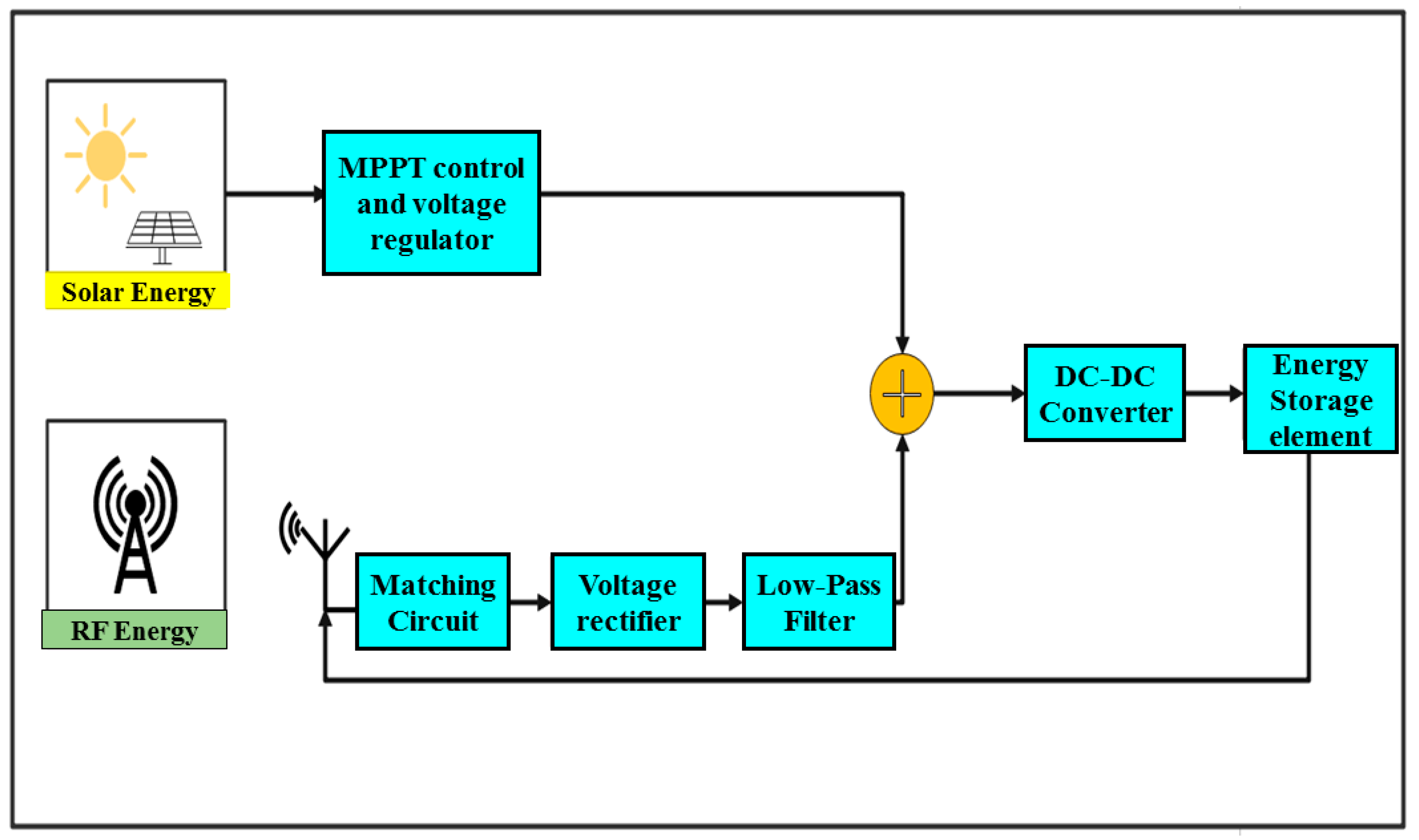
The block diagram in Figure 1 illustrates the conceptual design of the proposed HEH system, showcasing the components and their interconnections which include a receiver antenna, an L-matching network, halfwave doubler voltage rectifier circuit, battery, solar panel as well as an IP5306-based charging unit. The proposed system serves the purpose of supplying energy to power up an active RFID tag in outdoor environments. In this context, the solar cell panel holds a significant advantage as it can deliver high output power owing to the intense illumination typically found in outdoor settings. Furthermore, the system can harvest radio frequency (RF) energy from the surrounding environment. Additionally, to address situations where there may be insufficient sunlight or during nighttime, the system incorporates microwave power transmission techniques to provide energy for the hybrid solar-RF energy harvesting system. This ensures a continuous and reliable power supply even without sunlight.
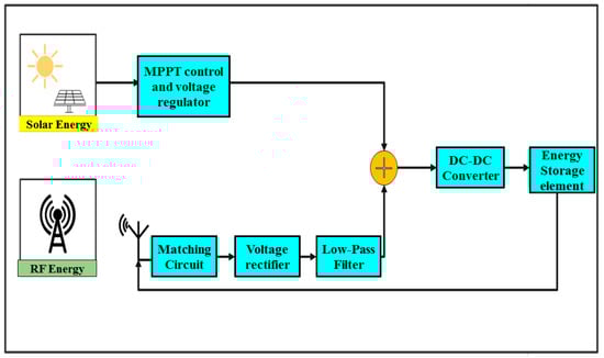
Figure 1.
Hybrid harvester block architecture.
This paper proposes a hybrid solar and wireless EH system. The hybrid energy harvesting system comprises the EM4325-embedded UHF RFID tag antenna, the solar cell panel, the charging circuit, a Li-Po battery, and the rectifier. The EH system operating frequency is 919 MHz. The proposed design approach exhibits a lower shading coefficient than other designs due to the MPPT algorithm present in the IP5305 IC that continuously adjusts the panel’s operating point to extract the maximum power under varying conditions, including shading. This can help maintain optimal performance even when some cells are partially shaded. As a result, the photo-electric conversion effect of the solar cell panel remains unaffected by shading. The RFID tag antenna is modeled with a meandered line and EM4325 chip. The proposed prototype realized a maximum PCE of 55.14% at an input power of 12 dBm. Thus, the hybrid system performance shows an enhanced PCE of 86.49%. The novelties of this approach are the mobility, the miniature size of the system, as well as their independent configuration unlike rectennas that are unified with the solar panels, for example in past researches as in [14]. To the best of our knowledge, this paper presents a novel method that combines mobility and a small compactness in a HEH system. The main contributions of the work focus on the following:
- The proposed design system boasts remarkable mobility and is characterized by its compact form factor, making it an ideal candidate for diverse applications. The portability and miniaturization of the system also establish a noteworthy foundation for advancing sustainable and self-sufficient energy solutions in the field of RFID technology.
- The proposed unique and independent configuration offers versatility and adaptability to the system. This setup allows for optimized RF and solar energy harvesting components, potentially enhancing overall efficiency and performance.
The remaining sections of this paper are arranged in the following manner: Section 2 and Section 3 delve into the details of the proposed antenna and RF rectifier design. Section 4 encompasses the presentation and analysis of the solar energy harvesting (SEH) system design. Finally, we conclude this paper in Section 5.
2. Antenna Design
In this work, the proposed antenna structure for capturing ambient RF signals is a meander line antenna. It is deployed in the RFID tags as they have the advantage of being lightweight, compact, and conformal, providing good efficiency and bandwidth (BW) and improving performance when combined with RF ICs [21,22]. In this case, the meander line antenna is chosen to store an EM4325 RF IC, representing the antenna’s source impedance. The proposed UHF RFID tag antenna is designed and optimized in CST 2019. This software package is designed for high-performance 3D electromagnetic (EM) analysis, enabling the design, research, and optimization of various EM components and systems. In this work, a meander line antenna with a quarter-wavelength structure is designed to achieve resonance at the desired frequency of 919 MHz. The antenna impedance is of a complex value since an RF chip is added; hence, the antenna chip impedance is matched to obtain a proper attenuation at 919 MHz, which is close to the UHF-RFID 915 MHz band. The reason 919 MHz is chosen because it offered the best resonance for the particular antenna design. Moreover, the radiation patterns are also observed to monitor the characteristics of the designed antenna.
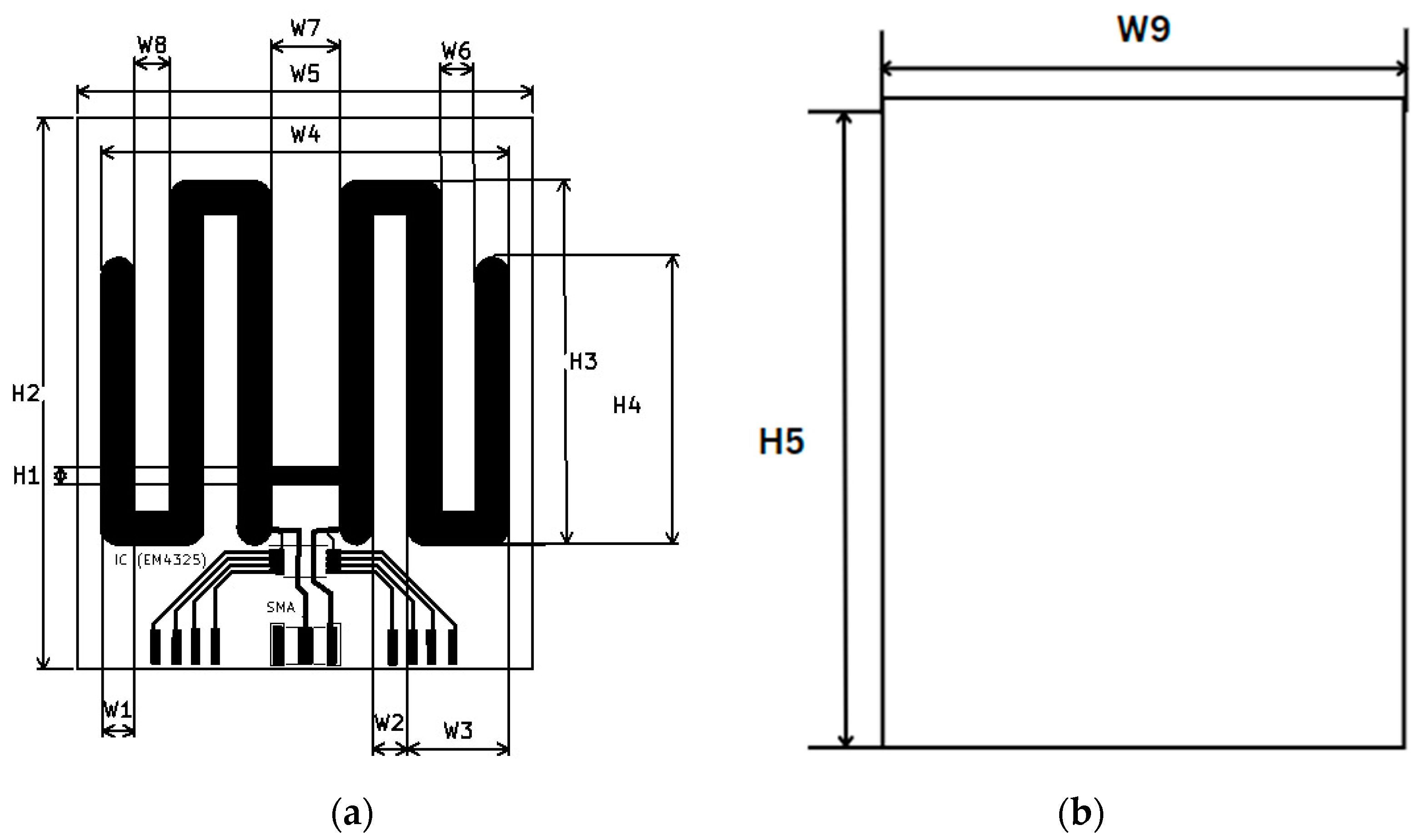
The completed design of the meander line antenna, featuring a 50 Ω excitation and lumped element ports positioned at the midpoint of the feed line, is illustrated in Figure 2. The 50 Ω excitation (red arrow) designates the connection of the antenna output to the 50 Ω SMA connector, while the lumped element port (blue arrow) is used to attach the EM4325 chip impedance of . The center frequency is 919 MHz. Therefore, the wavelength λ = 327 mm and the maximum electrical length is 82 mm, for a quarter-wave antenna that operates from 860 to 960 MHz, with a BW of 13.5 Hz. The RFID antenna is fed by 50 Ω coaxial. The quarter-wave antenna is selected because it has the advantage of being smaller and attenuating at the desired frequency. The antenna impedance is the antenna chip impedance, which typically consists of a resistance of 1717 Ω and a capacitance of 1.52 pF; this is part of the RF chip in the tag configured in a parallel topology. The values and arrangement of these components are chosen to achieve the desired impedance transformation. This step is crucial in preparing the RF waves for transmission to the rectifier circuit.
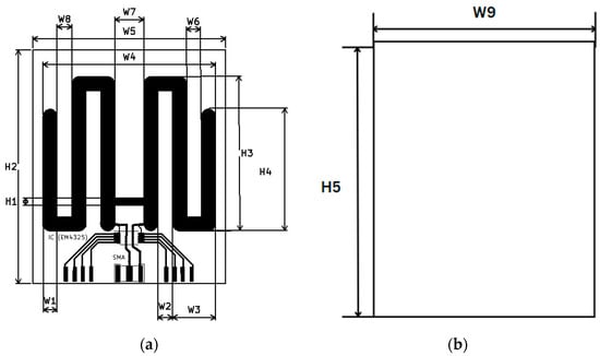
Figure 2.
Antenna geometry (a) Front view, (b) Back view.
Under the above conditions, the radiation pattern of the RFID antenna is the direction of the bidirectional path (backfire and endfire radiation). In the context of bidirectional radiation, it is essential to note that the direction of maximum gain is perpendicular to the broadside radiation, known as endfire radiation. This means that the primary radiation direction aligns with the maximum radiation direction of the RFID antenna. Additionally, it is essential to ensure that the antenna possesses both high gain and wide bandwidth to meet the requirements. Based on the description provided, approximately 70 antenna simulations were conducted to evaluate the antenna’s performance. These simulations confirmed that the antenna meets the required specifications. As a result, the optimized results were used to manufacture the tree-shaped antenna. The specific configuration and dimensions of the proposed antenna can be seen in Figure 2a for the front dimensions, Figure 2b for the back dimensions and Table 1, respectively.

Table 1.
Key parameters of the proposed antenna.
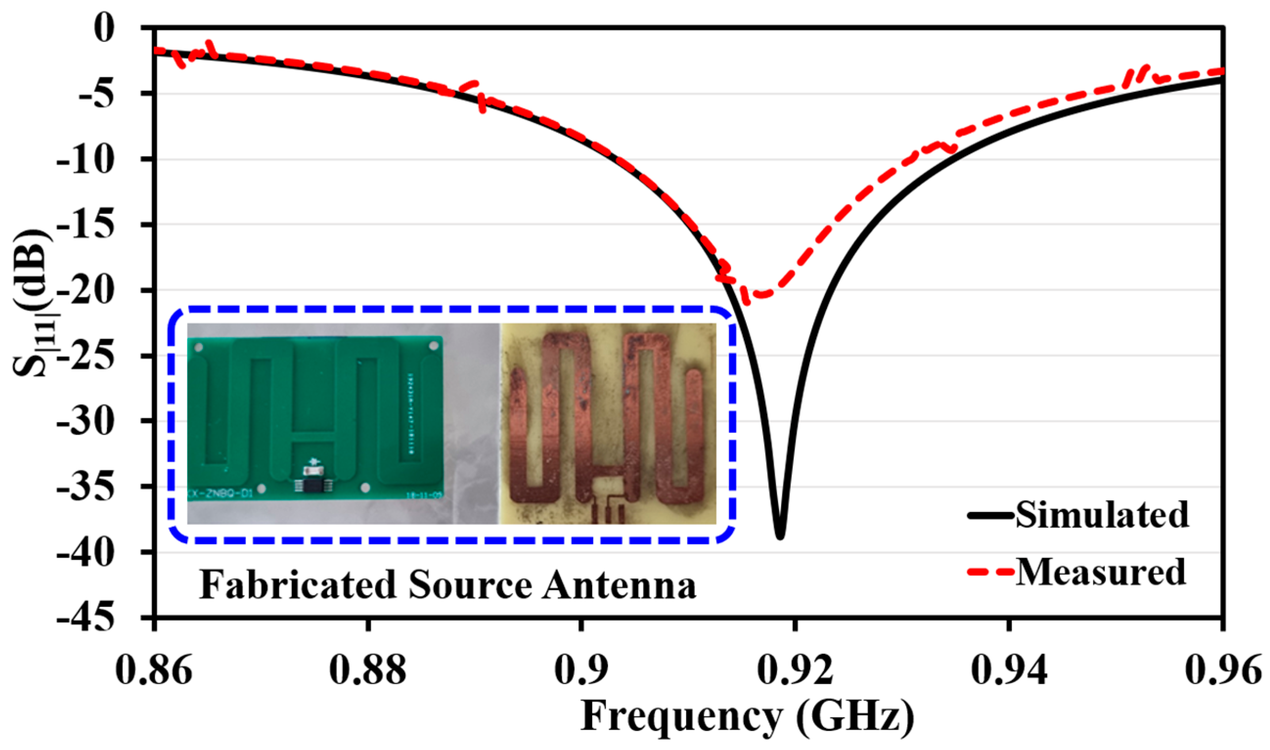
The antenna’s ultimate configuration encompasses a metallic meander line on a grounded dielectric substrate with minimal electrical thickness. The antenna fabrication is achieved on the designed FR-4 substrate. The fabricated antenna prototype is shown in Figure 3 along with the results.

Figure 3.
Antenna results.
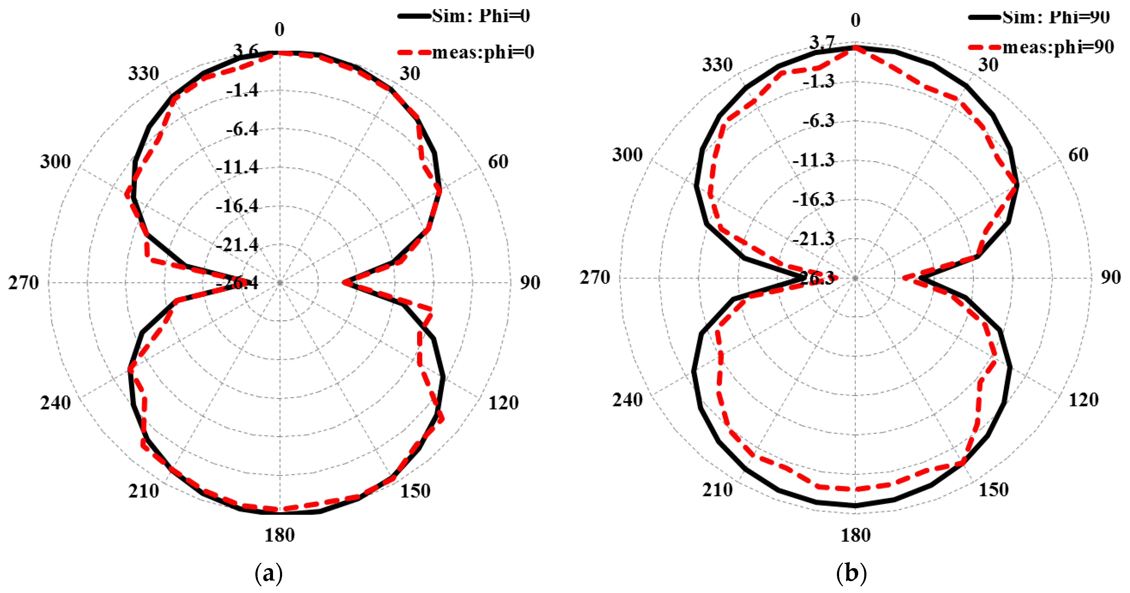
The peak gain of 3.54 dB is realized through measurement, and the measured and simulated radiation patterns are shown in Figure 4a,b. The antenna excitation is positioned on the E-plane at Phi = 0 and H-plane at phi = 90. It is observed that the beams are of a cross-polarization nature, whereby the antenna forms a plus (+) sign or a cross (×) shape. For example, they are oriented at right angles (90°) to each other, and the measured results reasonably agree with the simulated results.
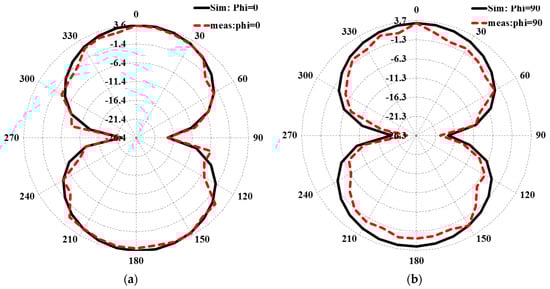
Figure 4.
Farfield plots (a) phi 0°; (b) phi 90°.
The comparison between the simulated and measured results for the antenna can be observed in Figure 4. The simulated value is observed to be −38.8 dBm, while the measured value is at −19.32 dBm. The source antenna achieved a simulated and measured BW and fractional percentage bandwidth (FBW) of 0.9024 to 0.9354 MHz and 0.9034 to 0.9310 MHz, respectively. Compared to the simulated results, the observed differences in the attenuation of both the antenna and rectifier measurement results can be attributed to various factors. These factors include the manual fabrication of the components, the losses, heat dissipation occurring in the conductor and substrate layers, and the tolerances present in the fabrication process.
3. Rectifier Design
3.1. The Rectifier Principle Analysis
This section presents the design of a compact and efficient parallel double-diode RF rectifier. The choice of diode connection topology directly impacts the RF-to-DC conversion efficiency of the rectifier. Single-diode series and parallel connections are considered the most efficient among various connection topologies. The proposed rectifier consists of four key components to optimize the conversion efficiency: a matching network, a diode, and a DC pass filter. The original data is optimized using ADS 2019 software to achieve optimal conversion efficiency. The schematic diagram of the rectifier can be seen in Figure 5. Table 2 also provides the parameters of the proposed rectifier. It is important to note that the nonlinear rectification of the diode generates higher harmonics, which can reduce the rectification efficiency. However, the matching network and the DC pass filter help constrain the higher harmonics, improving overall performance. Furthermore, the stubs are added individually until a perfect attenuation is observed on the input reflection coefficient panel. The objective is to ensure that the transmission line size remains below 15.04 mm to minimize the impact of transmission line width. The width of the lines is adjusted to match the dimensions of the component connectors, aiming to reduce transmission losses.
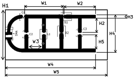
Figure 5.
Rectifier EM layout.
Table 2.
Key parameters of the proposed rectifier.
We notice that the L-matching network is lossy in nature. The tuned and optimized components are impossible to find in the real world due to their fine values. Hence, variable capacitors, inductors, or commercial lumped elements close to the optimized values are used. This would result in the imperfection of the results upon completion of impedance matching. It is possible to utilize a stub matching network to enhance the matching accuracy and reduce losses caused by passive components. The stub matching network was designed on ADS and added to the circuit. The transmission line design is implemented in ADS software using the TLines, MTEE, MSTEP, and MLOC lines available in the ADS library. The rectifier is matched through an SS24, Surface Mount Schottky Barrier diode.
3.2. The RF Rectifier Measurement
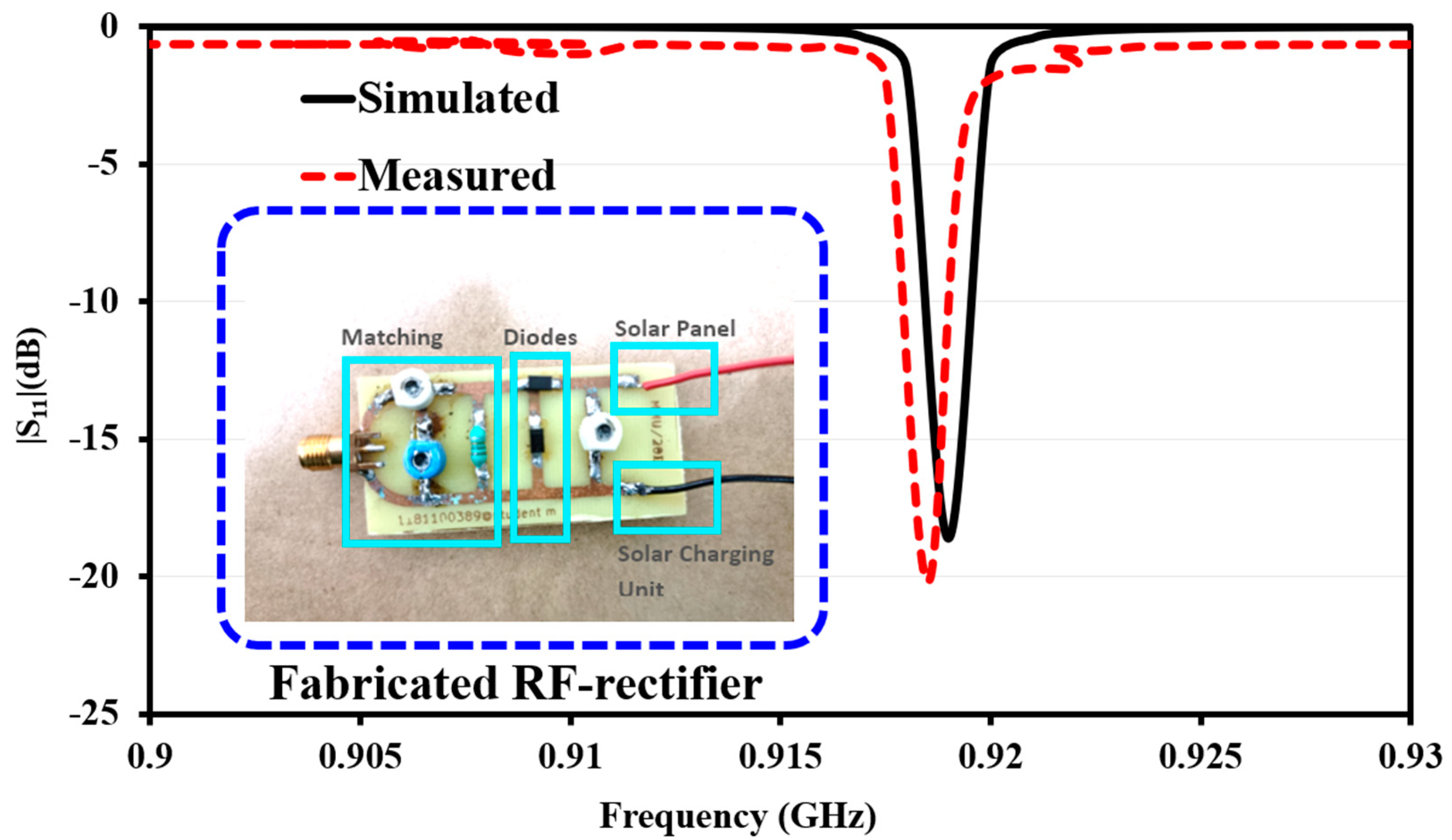
Figure 6 illustrates the corresponding results for the measured and simulated rectifier under an input power of −20 dBm. The simulated value is observed to be −18.62 dBm, while the measured value is at −20.21 dBm. The observed differences in the attenuation of both the antenna and rectifier measurement results, compared to the simulated results, can be attributed to many factors; in this case, we see that the measured results fare higher than the simulated. Variations in dimensions, alignment, and soldering can lead to variations in antenna performance among different fabricated units. The presence of variable capacitors helps increase rectifier return loss by allowing for the fine-tuning of the impedance matching between the rectifier circuit and the load. Variable capacitors can compensate for component variations and tolerances in the rectifier circuit. These variations can impact impedance matching and lead to suboptimal return loss. By adjusting the capacitance, the variable capacitors can help mitigate the effects of component variations and improve overall performance.

Figure 6.
Rectifier results.
Based on the design principle, the rectifier is fabricated on a substrate with a dielectric constant () of 4.65 and a thickness (h) of 1.6 mm. The layout of the rectifier has dimensions of 17 mm × 35 mm. During testing, an analog signal generator (analog signal source) covering RF and microwave frequency ranges from 9 kHz to 12 GHz (Anapico, APSIN12G) is used to supply the rectifier, and the voltage across the DC load is measured using a multimeter. These signal generators have sound signal output, low phase noise, and high switching speed. Moreover, their compact size, lightweight design, and low power consumption make them highly advantageous for laboratory applications, production facilities, and outdoor environments. Their versatility and efficiency make them indispensable tools in various fields, allowing for precise signal generation and reliable performance in diverse testing and production scenarios. Figure 7 depicts the measurement setup for the proposed rectifier, which uses a 12 GHz signal generator.
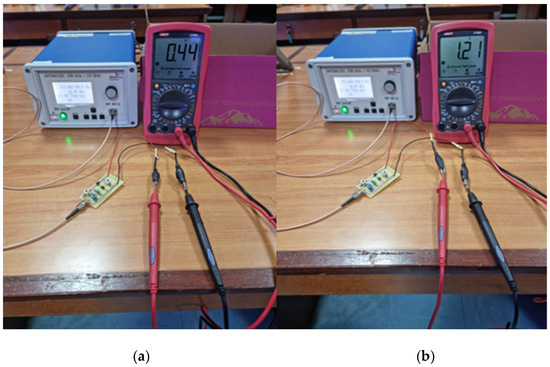
Figure 7.
Measured output voltage using a signal generator at (a) −20 dBm and (b) −10 dBm.
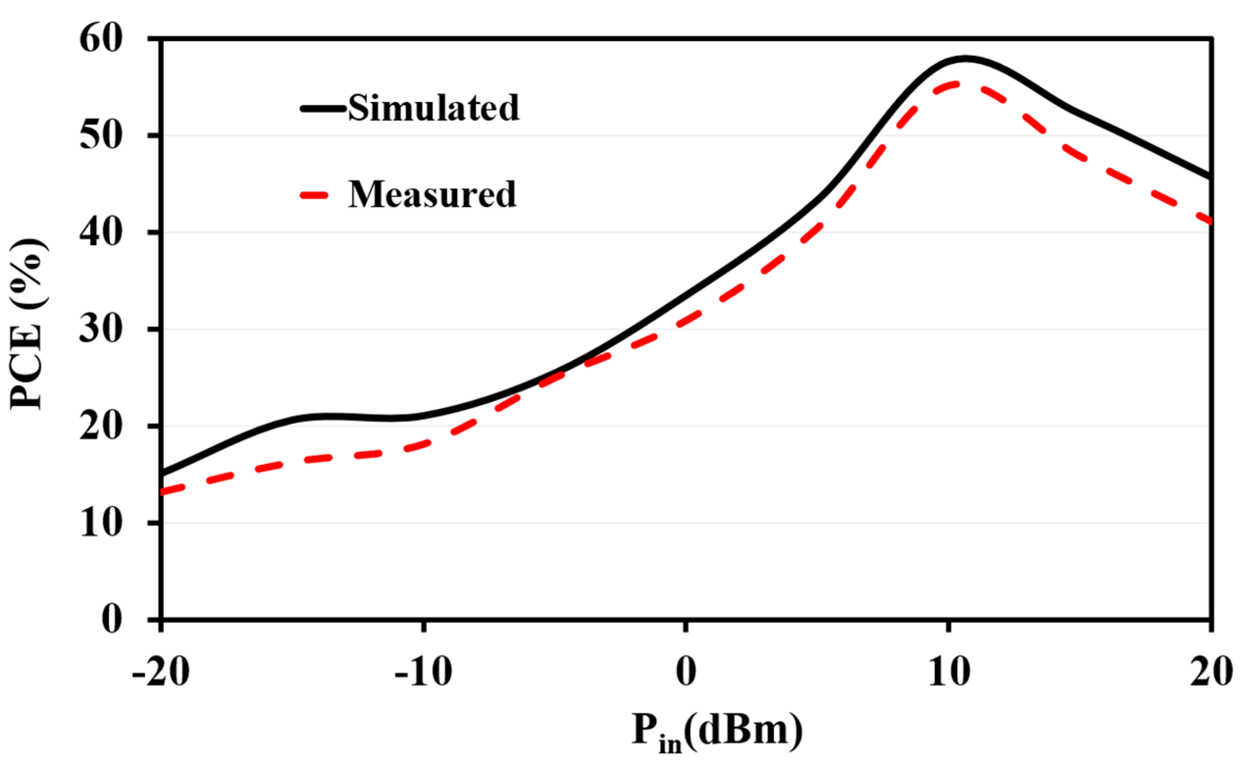
Based on Figure 8, it is clear that the RF energy harvesting circuit attains a peak PCE of 55.14% at the operating frequency of 919 MHz when the input power is at 12 dBm and an output power () of 2.04 W and output voltage of 3.24 V. It is calculated with the aid of Equations (1) and (2).
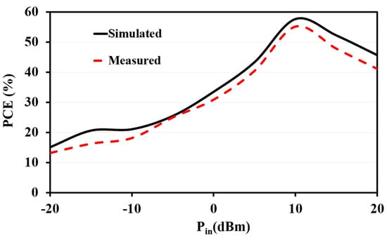
Figure 8.
RF harvester PCE (%) vs. input power (Pin).
We also notice that the RF energy harvester provides a reasonably consistent PCE until 12 dBm and decreases afterward. The RF energy harvester provides satisfying results based on the measurement analysis. The measured RF-to-DC efficiency at different RF input power levels and frequencies is illustrated in Figure 8. The results indicate that the RF-to-DC performance varies for a 919 MHz frequency at different input power ranges. At an input power of −12 dBm, the conversion efficiency surpasses 18.1%. The PCE decline beyond 12 dBm is attributed to the limitations of the harvester’s maximum VDC generation capacity. Losses such as heat dissipation, current leakage, and parasitic loss can result in the downfall of the generated output voltage. Notably, the circuit demonstrates a compact structure and exhibits a high RF-to-DC conversion efficiency.
4. Solar Energy Harvesting System
PV cells, also known as photovoltaic cells, can be fabricated using countless methods and materials. Despite their variations, their fundamental purpose remains consistent: capturing solar energy and transforming it into electricity that can be utilized. Three primary PV cell technologies dominate the global market: monocrystalline, polycrystalline silicon, and thin film. These technologies have established themselves as the frontrunners in the industry.
Monocrystalline silicon cells emerge as the predominant choice among commercial PV cell types due to their extensive utilization across various sectors. Apart from their established role in space applications, these cells have demonstrated successful integration in navigation, astronomy, railway systems, agriculture, meteorology, and animal husbandry. Approximately 95% of the solar cells sold these days are silicon semiconductor materials [23]. The productivity levels of monocrystalline cells are among the highest in the industry, primarily due to using a significant amount of pure crystalline silicon during their production. The effectiveness of these panels ranges from 20% to 22%, depending on the quality of the mono panel. Table 3 provides the survey on the types of available solar panels.
Table 3.
Survey on the types of available solar panels.
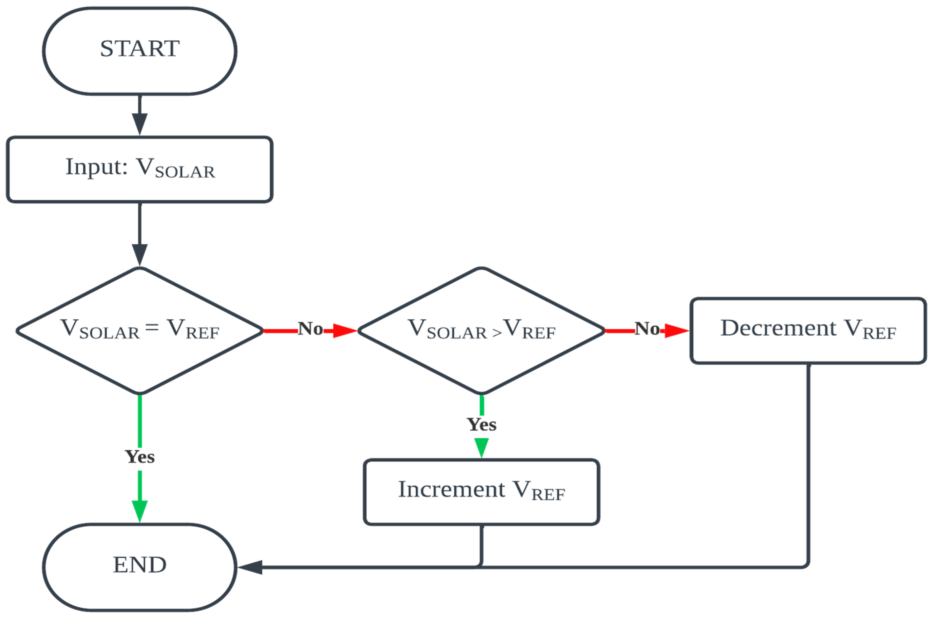
The process of measuring power, comparing it to the operating voltage, and changing it is performed regularly to track and optimize the operating point continually. The controller performs fine-tuned modifications to keep the system at the MPP while accounting for ambient variables and sun irradiation changes. The MPPT controller optimizes the power output of the PV system by altering the operating voltage depending on power measurements. Figure 9 demonstrates the flowchart of the proposed maximum power point tracking algorithm, which is the fractional open voltage (FOV) algorithm which is inbuilt in the IP5306 IC’s switch buck charging and boosting capabilities. Integrated power-path management and multiple protections including short-circuit protection are provided in this IC. The IP5306 is a fully integrated multi-function power management SoC. The system combines a boost converter, a management system for charging a Li-ion battery, and a controller that indicates the battery’s state of charge.
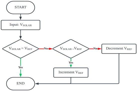
Figure 9.
Proposed maximum power point tracking algorithm flowchart.
Figure 10 illustrates the solar energy harvesting circuit developed for this work. The circuit serves as a module dedicated to harvesting solar energy. Notably, the circuit incorporates an IP5305 IC which consists of an inbuilt FOV MPPT algorithm, facilitating MPPT and offering features like self-discharge and round-trip efficiency. To ensure stable operation, capacitors have been included in the circuit to mitigate ripple voltage. Additionally, the presence of LEDs indicates the solar panel’s battery percentage, with distinct levels represented at 25%, 50%, 75%, and 100%.
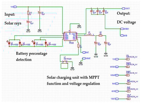
Figure 10.
Schematic of the Solar energy harvester subsystem.
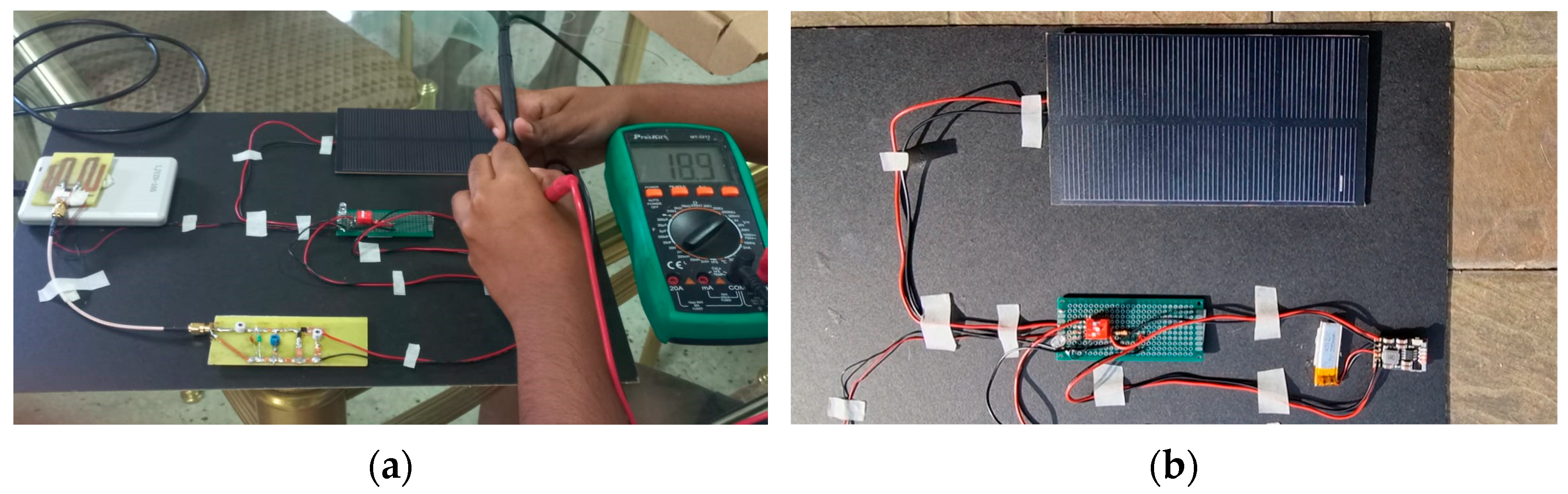
Figure 11 depicts the testing performed on the solar energy harvester at (a) 1 pm indoor environment and (b) 10 am outdoor environment. Varying light intensities help improve our understanding on how the solar irradiance levels have an effect on the output power obtained by the solar energy harvesting circuit. At an indoor environment, we notice that the output voltage obtained is as 1.89 V while at a bright outdoor setting, the output voltage was observed to be 2.36 V.

Figure 11.
Solar harvester tested at different light intensities: (a) 1 pm (b) 10 am.
Based on Figure 8, it is clear that the RF energy harvesting circuit attains a peak PCE of 55.14% at the operating frequency of 919 MHz when the input power is at 12 dBm. It is calculated with the aid of Equations (1) and (2).
where:
- = PCE;
- = Solar energy harvester PCE;
- = Input power;
- = Output power;
- = Input power from solar cell and battery.
The tabulated results distinguish that the PCE at the peak for the solar harvester is realized at 80.20% with an output power of 3.0211 W, as seen in Figure 12, according to the tabulated data analysis in Table 4, when the current level of 0.580 A and voltage of 5.21 V are measured. The utilization of a rechargeable battery not only facilitates higher energy storage capacity but also contributes to enhancing the effectiveness of the harvester unit compared to the efficiency without a battery supply. This observation highlights the positive impact of incorporating a rechargeable battery on the system’s overall performance. The output voltage is regulated at 5 V due to Ohm’s law. Hence, the values that decrease from 5.21 V onwards are not considered. The HEH measurement setup is depicted in Figure 13.
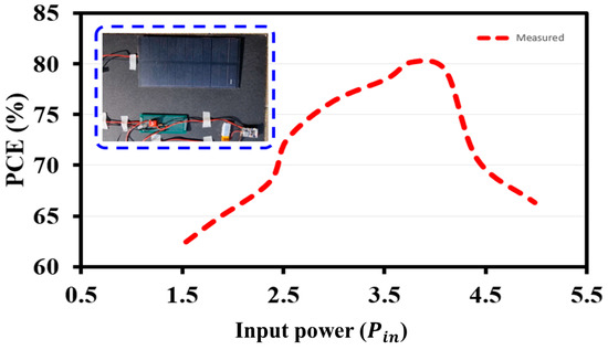
Figure 12.
Solar harvester PCE (%) vs. (Pin).
Table 4.
Measured results for PCE for the solar energy harvester.
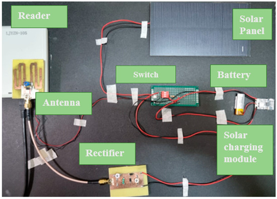
Figure 13.
HEH measurement setup.
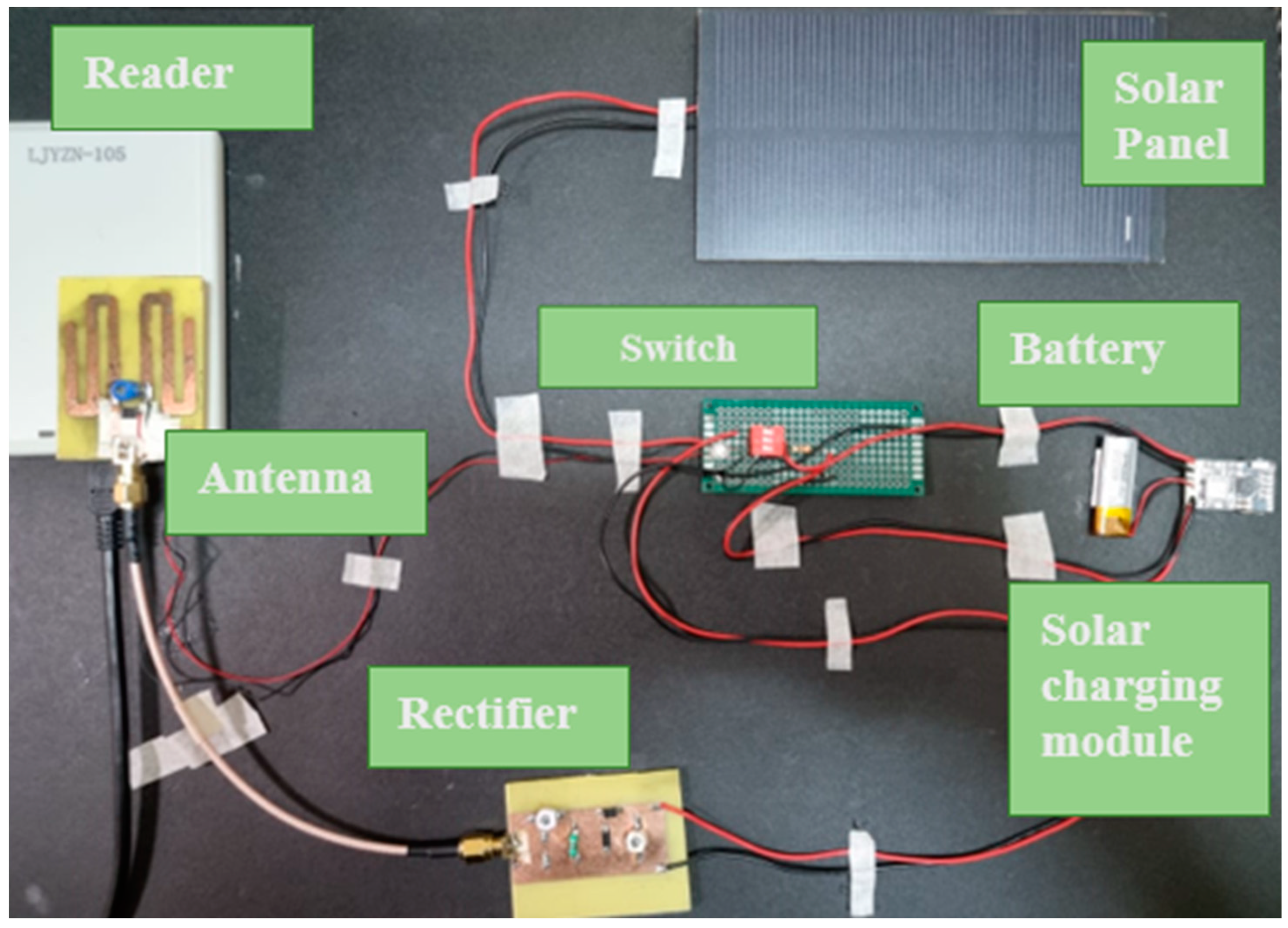
With regard to the fabricated tag, it is noticed that the 45° elevation provided the greatest read range among the three elevation angles at an input power of 15 dBm. The angle of elevation is chosen as the reference antenna (which the fabricated antenna design is based on) used was tested for an input power of 10 dBm at different angle of elevations. This angle that provided the highest read range was selected and tested with different input powers for the fabricated tag. Therefore, the antenna which is designed is designed in such a way that it has to surpass the current reference antenna’s read range. The read range of a near field tag reader, also known as an UHF (Ultra-High Frequency) Near Field RFID (Radio Frequency Identification) reader, in this case, a LJYZN-105 reader, is used due to the budget limit for the project. It runs at the UHF frequency range of 902 MHz to 928 MHz, and its read range is normally restricted to a maximum of 18 cm. Figure 14 shows the reader observation during testing phase and HEH measurement setup.
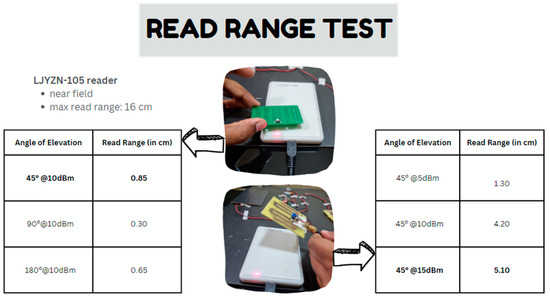
Figure 14.
Reader observation during testing phase and HEH measurement setup.
5. Hybrid Harvesting System Measured
The standalone systems are integrated and subjected to an efficiency experiment to evaluate the overall performance and peak efficiency of the harvesting unit. This experiment aims to assess the collective effectiveness of the system and measure the highest efficiency achieved by the harvesting unit. The DC combining circuit is connected in series and attached to a switching mechanism to turn battery-assisted passive (BAP) and active modes on and off for the RFID antenna and to charge the solar panel.
For this work, the input will be the total power coming from both harvesting sources, where the input for the solar harvester originates from both the solar cell and LiPo battery. In contrast, the total energy collected for the RF harvester comes from the rectifying circuit and the LiPo battery storage. The measurement explanation for the total power generated by the combined harvester circuit can be described as follows:
where,
- = Hybrid harvester PCE
- = Combined input power from both RF and Solar energy harvesters.
- = Overall output power generated
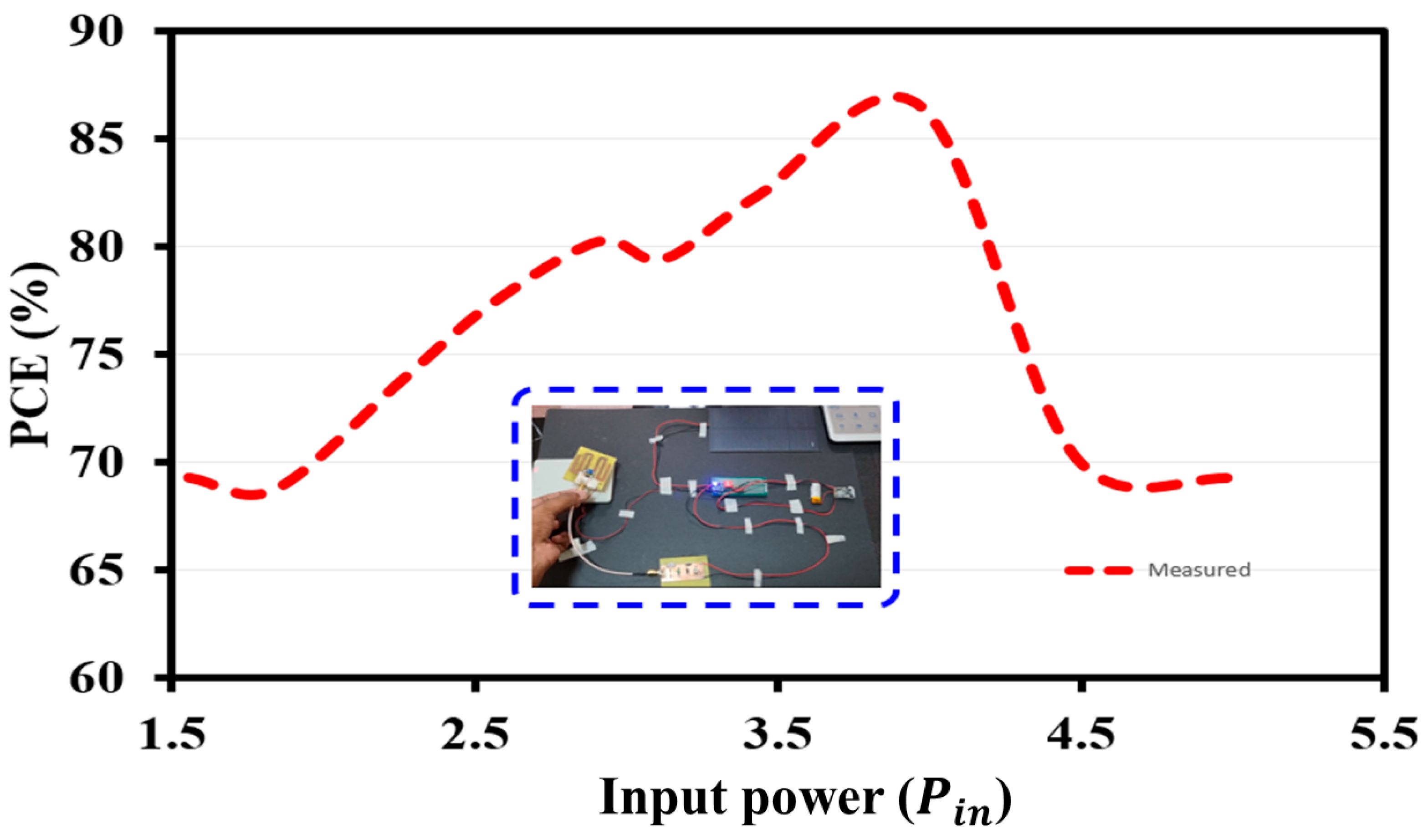
Figure 15 illustrates that the hybrid energy harvester’s peak PCE reaches 86.49%. This optimal efficiency is attained when the input power is 3.92 W, resulting in an output voltage of 5.35 V and an output current of 0.634 A. These findings demonstrate the hybrid harvester’s effective conversion of received DC power. The system incorporates a rechargeable battery, crucial in supplying power as it can be recharged and replenished. Notably, the hybrid harvester exhibits a higher output power of 3.39 W, compared to standalone harvesters, indicating improved performance and enhanced power delivery capabilities to the load, such as the LiPo battery. This voltage increase confirms the RF harvester’s significant contribution to the hybrid system’s power generation. It is worth mentioning that any losses experienced in the system can be attributed to factors such as fabrication tolerance, parasitic losses, or faulty components. Furthermore, it should be noted that using a breadboard and jumper wire connections introduces resistance, which leads to converting electrical energy into heat energy. This dissipation of heat occurs in the surrounding area. Additionally, the efficiency of the hybrid harvester system is considerably higher compared to a standalone solar energy harvester.

Figure 15.
HEH PCE (%) vs. (Pin).
Table 5 summarizes the performance comparison between the proposed design and existing designs. Unlike the approach in [14], which directly employs a solar panel for EH, our current work introduces an intelligent HEH system that is compact and separate from the RF harvester. This separation is deliberate to facilitate troubleshooting in case of issues or malfunctions in the EH system. Attaching a rectenna system directly to the solar panel would pose difficulties in identifying and resolving problems. Conversely, by integrating these subsystems individually, we can quickly pinpoint the root cause of any issues, making troubleshooting much more accessible. Moreover, since these subsystems are integrated rather than physically attached, the failure of one energy harvesting system does not affect the functioning of the other. This innovative approach results in a significant increase in output power and PCE. We integrate a rechargeable battery and a DC-DC converter to further enhance the power drawn from the HEH system. In comparison, the maximum output power achieved in [16], without the inclusion of a battery supply, was a mere 0.7 W. Our proposed HEH system overcomes this limitation by incorporating a robust hardware charging management unit, which effectively handles the energy storage element, thereby improving the system’s resilience.
Table 5.
Summary on performances of related research.
The proposed HEH system provides convenient power transfer functionality, allowing for smooth power utilization from either the solar panel, battery, or a combination of both sources. Additionally, the system design incorporates an efficient charging mechanism for the lithium battery. In cases where the output voltage drops below a specified threshold, this condition can be indicated through LED lights on the charging module. This feature helps extend the battery’s lifespan and includes a reliable protective mechanism, thereby reducing the necessity for frequent maintenance. In contrast to the systems suggested in [29,30], which lack comprehensive protection features, the proposed design offers enhanced security.
Overall, the proposed hybrid energy harvesting system is characterized by its robustness, safety, high efficiency, minimal power loss, and simple design. The obtained results demonstrate that it achieves the desired output power and a high PCE, making it an effective solution for harvesting both solar and wireless energy.
6. Conclusions
This paper presents the development of a hybrid RF-Solar EH unit that combines RF wave harvesting from the GSM 900 band with solar energy. The motivation behind the design of a custom circuit with an IP5306 IC is for skill learning and development. The antenna and rectifier circuit are optimized using meandered line and variable capacitor elements. The hybrid system effectively captures RF waves and solar energy for power generation in order to improve the tagging distance of the fabricated EM4325-based active RFID tag at 919 MHz, which is extremely close to the UHF 915 MHz band. The rectenna prototype performs well, while the solar energy harvesting unit achieves a peak PCE of 80.20% at 10 dBm. The combined output from both subsystems demonstrates a peak efficiency of 86.49% at 15 dBm, making the hybrid energy harvester suitable for providing continuous power supply for an active RFID tag and increase the tagging distance from 0.85 cm to 5.10 cm. To further enhance efficiency, the system can be linked to a supercapacitor for increased output power and continuous charging during periods of low sunlight.
Author Contributions
S.G.V.: design technique; S.G.V. and S.M.: software implementation; S.G.V.: evaluation and validation; S.M., S.K.W. and J.J.T.: formal examination; S.G.V. and S.M.: investigation, S.M. and J.J.T.: supplies and resources; J.J.T. and S.K.W.: collection of data; S.G.V. and S.M.: composing—first draft and preparations of draft; S.G.V. and S.M.: composing—reviewing and editing; S.M., J.J.T. and S.K.W.: visibility; S.M., J.J.T. and S.K.W.: supervisory; J.J.T. and S.K.W.: project management. All authors have read and agreed to the published version of the manuscript.
Funding
The funding for this research was received from Multimedia University, R&D Malaysia; Multimedia University with project number MMUI/230010.
Data Availability Statement
The data that support the findings of this study are available from the corresponding author upon reasonable request.
Acknowledgments
This work is supported by Multimedia University R&D Malaysia.
Conflicts of Interest
The authors declare no conflict of interest.
References
- Lai, K.-L.; Joy, I.; Zong, C. Development of Smart Cities with Fog Computing and Internet of Things. J. Ubiquitous Comput. Commun. Technol. (UCCT) 2021, 3, 52–60. [Google Scholar]
- Yadav, P.; Vishwakarma, S. Application of Internet of Things and Big Data towards a Smart City. In Proceedings of the 3rd International Conference On Internet of Things: Smart Innovation and Usages (IoT-SIU), Bhimtal, India, 23–24 February 2018. [Google Scholar]
- Mohammed, S.K.N.K.; Alsharif, H. Energy Harvesting Techniques for Wireless Sensor Networks/Radio-Frequency Identification: A Review. Symmetry 2019, 11, 24. [Google Scholar]
- Mohammadi, A.A.-F.M. Enabling Cognitive Smart Cities Using Big Data and Machine Learning: Approaches and Challenges. IEEE Commun. Mag. 2018, 56, 94–101. [Google Scholar] [CrossRef]
- Fu, Y.; Sun, S.; Wang, Z.; Niu, P.; Zhang, M.; Chen, S.; Pang, W. Piezoelectric micromachined ultra-sonic transducer with superior acoustic outputs for pulse-Echo imaging application. IEEE Electron Device Lett. 2020, 41, 1572–1575. [Google Scholar] [CrossRef]
- Mahapatra, S.D.; Mohapatra, P.C.; Aria, A.I.; Christie, G.; Mishra, Y.K.; Hofmann, S.; Thakur, V.K. Piezoelectric Materials for Energy Harvesting and Sensing Applications: Roadmap for Future Smart Materials. Adv. Sci. 2021, 8, 1–73. [Google Scholar] [CrossRef] [PubMed]
- Liu, C.; Zhao, C.; Liu, J.; Wang, J.; Wang, Y.; Fan, Y.; Zhao, K.; Shan, B.; Qu, Z.; Ma, K.; et al. Design and study of a combining energy harvesting system based on thermoelectric and flapping triboelectric nanogenerator. Int. J. Green Energy 2021, 18, 1302–1308. [Google Scholar] [CrossRef]
- Chen, Y.; Shi, C.; Zhang, J.; Dai, Y.; Su, Y.; Liao, B.; Zhang, M.; Tao, X.; Zeng, W. Ionic Thermoelectric Effect Inducing Cation-Enriched Surface of Hydrogel to Enhance Output Performance of Triboelectric Nanogenerator. Energy Technol. 2022, 10, 2200070. [Google Scholar] [CrossRef]
- Gang, M.; Shitong, F.; Suo, W.; Shengxi, Z. A low-frequency rotational electromagnetic energy harvester using a magnetic plucking mechanism. Appl. Energy 2022, 305, 117838. [Google Scholar]
- Zhao, L.; Zou, H.; Gao, Q.; Yan, G.; Wu, Z.; Liu, F.; Wei, K.; Yang, B.; Zhang, W. Design, modeling and experimental investigation of a magnetically modulated rotational energy harvester for low frequency and irregular vibration. Sci. China Technol. Sci. 2020, 63, 2051–2062. [Google Scholar] [CrossRef]
- Muhammad, S.; Tiang, J.J.; Wong, S.K.; Smida, A.; Ghayoula, R.; Iqbal, A. A Dual-Band Ambient Energy Harvesting Rectenna Design for Wireless Power Communications. IEEE Access 2021, 9, 99944–99953. [Google Scholar] [CrossRef]
- Singh, M.; Agrawal, S.; Parihar, M.S. Design of a rectenna system for GSM-900 band using novel broadside 2 × 1. J. Eng. 2017, 2017, 232–236. [Google Scholar] [CrossRef]
- Sridhar, N.H.; Anitha, G.S.; Sumathi, M.S. Analysis of energy harvesting from multiple sources for wireless sensor networks with focus on impedance matching. In Proceedings of the 2017 International Conference on Circuit, Power and Computing Technologies (ICCPCT), Kollam, India, 20–21 April 2017. [Google Scholar] [CrossRef]
- Deo, A.; Reddy, G.S.; Arrawatia, M.; Shah, P. A Partially Transparent GSM Band Loop RF-Solar Energy Harvester. In Proceedings of the IEEE Microwaves, Antennas, and Propagation Conference (MAPCON), Bangalore, India, 12–16 December 2022. [Google Scholar]
- Omar, A.S.; Amer, A.; Imran, K.; Bong, J.C. A Hybrid Energy Harvesting Design for On-Body Internet-of-Things (IoT) Networks. Sensors 2020, 20, 407. [Google Scholar]
- Gurinder, S.; Fatima, M.; Vivek, A.B.; Anand, S. Experimental Observations on Hybrid RF-Solar Energy Harvesting Circuit for Low Power Applications. In Proceedings of the IEEE International Conference on Advanced Networks and Telecommunications Systems (ANTS), Indore, India, 16–19 December 2018. [Google Scholar]
- Sekander, S.; Tabassum, H.; Hossain, E. Statistical Performance Modeling of Solar and Wind-Powered UAV Communications. IEEE Trans. Mob. Comput. 2020, 20, 2686–2700. [Google Scholar] [CrossRef]
- Peter, T.; Rahman, T.A.; Cheung, S.W.; Nilavalan, R.; Abutarboush, H.F.; Vilches, A. A Novel Transparent UWB Antenna for Photovoltaic Solar Panel Integration and RF Energy Harvesting. IEEE Trans. Antennas Propag. 2014, 62, 1844–1853. [Google Scholar] [CrossRef]
- Muhammad, S.; Tiang, J.J.; Wong, S.K.; Smida, A.; Waly, M.I.; Iqbal, A. Efficient quad-band RF energy harvesting rectifier for wireless power communications. AEU—Int. J. Electron. Commun. 2021, 139, 153927. [Google Scholar] [CrossRef]
- Oisin, O.; Kansheng, Y.; Patrick, M.; Max, J.A. Amorphous Silicon Solar Vivaldi Antenna. IEEE Antennas Wirel. Propag. Lett. 2015, 15, 893–896. [Google Scholar]
- Sharma, P.K.; Priyanka, S.; Chamanthi, K.; Satish, A.G.; Kaushik, A.V.S. A Wide Band Meander Line Antenna for RF Energy Harvesting. In Proceedings of the 2nd International conference on Electronics, Communication and Aerospace Technology (ICECA 2018), Coimbatore, India, 39 March 2018. [Google Scholar]
- Riccardo Colella, L.C. Single-Chip Gen2-Compliant UHF RFID Sensor Tags based on Novel Pseudo-BAP Mode. In Proceedings of the 2nd URSI Atlantic Radio Science Meeting (AT-RASC), Gran Canaria, Spain, 28 May–1 June 2018. [Google Scholar]
- Pay, E.Y.; Tiang, J.J.; Muhammad, S.; Chuah, T.C. Design of an efficient solar energy harvesting system for wireless power communication. Int. J. Numer. Model. Electron. Netw. Devices Fields 2023, 36, e3054. [Google Scholar] [CrossRef]
- Isworo, P.; Retno, A.D. Characteristics Surface Temperature of Solar Cell Polycrystalline Type to Output Power. In Proceedings of the 3rd International Conference on Energy, Environmental and Information System (ICENIS 2018), Semarang, Indonesia, 21 December 2018. [Google Scholar]
- Nerat, M. Copper–indium–gallium–selenide (CIGS) solar cells with localized back contacts for achieving high performance. Sol. Energy Mater. Sol. Cells 2012, 104, 152–158. [Google Scholar] [CrossRef]
- Alessandro, R.; Elisa, A.; Daniele, M. Low substrate temperature CdTe solar cells: A review. Sol. Energy 2018, 175, 9–15. [Google Scholar]
- Schropp, R.E.; Carius, R.; Beaucarne, G. Amorphous Silicon, Microcrystalline Silicon, and Thin-Film Polycrystalline Silicon Solar Cells. MRS Bull. 2007, 32, 219–224. [Google Scholar] [CrossRef]
- Dullweber, T.; Schmidt, J. Industrial Silicon Solar Cells Applying the Passivated Emitter and Rear Cell (PERC) Concept—A Review. IEEE J. Photovolt. 2016, 6, 1366–1381. [Google Scholar] [CrossRef]
- Muhammad, S.; Waly, M.I.; AlJarallah, N.A.; Ghayoula, R.; Negm, A.S.; Smida, A.; Iqbal, A.; Tiang, J.J.; Roslee, M. A multiband SSr diode RF rectifier with an improved frequency ratio for biomedical wireless applications. Sci. Rep. 2023, 13, 13246. [Google Scholar] [CrossRef] [PubMed]
- Dahmane, A.; Gianfranco, A.V.; Yvan, D.; Rachida, T. Harmonic Power Harvesting System for Passive RFID Sensor Tags, Smail Tedjini. IEEE Trans. Microw. Theory Tech. 2016, 64, 2347–2356. [Google Scholar]
- Jadhav, S.B.; Lambor, S.M. Hybrid Solar and Radio Frequency (RF) Energy Harvesting. In Proceedings of the IEEE International Conference on Power, Control, Signals and Instrumentation Engineering (ICPCSI), Chennai, India, 21–22 September 2017. [Google Scholar]
- Ankita, D.; Shrikanth, R.G.; Mahima, A.; Prashant, S. A Patch Rectenna Fed with L-probe to Harvest Solar and RF Energy. In Proceedings of the IEEE Microwaves, Antennas, and Propagation Conference (MAPCON), Bangalore, India, 12–16 December 2022. [Google Scholar]
- Muhammad, S.; Waly, M.I.; Mallat, N.K.; AlJarallah, N.A.; Ghayoula, R.; Negm, A.S.; Smida, A.; Iqbal, A. Wideband RF rectifier circuit for low-powered IoT wireless sensor nodes. AEU-Int. J. Electron. Commun. 2023, 170, 154787. [Google Scholar] [CrossRef]


Disclaimer/Publisher’s Note: The statements, opinions and data contained in all publications are solely those of the individual author(s) and contributor(s) and not of MDPI and/or the editor(s). MDPI and/or the editor(s) disclaim responsibility for any injury to people or property resulting from any ideas, methods, instructions or products referred to in the content. |
© 2023 by the authors. Licensee MDPI, Basel, Switzerland. This article is an open access article distributed under the terms and conditions of the Creative Commons Attribution (CC BY) license (https://creativecommons.org/licenses/by/4.0/).