Abstract
As the underwater environment is complex, the existence of obstacles will produce a certain collision interference to underwater robot operations, which causes the overall path planning and time costs to increase. In this paper, we propose a Tent chaotic mapping and dung beetle hybrid algorithm (MDBO) application for trajectory optimal planning and effective obstacle avoidance for an underwater telescopic arm robot. The method invokes the unique obstacle avoidance habit and foraging optimization idea of the dung beetle algorithm. Introducing it into the chaotic Tent mapping idea prevents the dung beetle algorithm (DBO) from falling into local optimality and increases the coverage of a global search. Simulation results show that the MDBO algorithm exhibits strong optimization ability and stability when multiple algorithms are verified using eight test functions. The MATLAB test reflects the performance indexes of the six joints of the underwater telescopic arm, and compared with various algorithms, the MDBO algorithm has an obvious convergence trend and strong global search ability. The algorithm is applied to real underwater experiments to verify that the improved dung beetle algorithm has better obstacle avoidance ability and reduces trajectory planning time by 30%, which helps the underwater robot to complete motion planning.
1. Introduction
As human beings explore and develop underwater resources, multi-objective searches for environmental targets have been widely researched and applied in the fields of medical surgery, narrow space search and rescue, and industrial equipment overhaul [1,2,3,4]. In view of the complexity and variability of the underwater environment, there are many underwater foreign objects that hinder a robot’s robotic arm from completing a capture, and the planning path of the capture target affects the overall capture efficiency. Therefore, it is important to adopt intelligent optimization algorithms to solve the trajectory planning of the robotic arm, especially for underwater autonomous operation, as collision avoidance and impact reduction [5] are important for a robotic arm to grasp its target.
The role of trajectory planning methods for robotic arms is mainly to achieve the time and energy optimization of the planned paths, which are now commonly known as cubic polynomials, quintic polynomials, and B-spline curve interpolation. These commonly used trajectory planning methods are concentrated in the fields of optical precision measurement [6], robotic arm path planning, and battery internal resistance metrology. However, the trajectory routes formed by a single interspersed time value [7,8] are less accurate, and the error coefficients caused by using them in special underwater environments are quite large. Therefore, this paper adopts a hybrid polynomial interpolation algorithm, the 5-5-5 polynomial trajectory interpolation, to form a joint trajectory. The 5-5-5 polynomial trajectory interpolation is superior for controlling the beginning and end shocks of the motion towards 0, which reduces the interference of obstacle avoidance and ensures that the whole motion planning process remains continuous and uninterrupted. Xia Xinhui et al. [9] addressed the friction-prone defects of grasping control for two-armed space robots. They used polynomial interpolation, which resulted in an envelope capture control that reduces frictional contact obstacle avoidance, lowers the operational planning path, and avoids capture target escape, given that robots employing robotic arm grasping control need to accomplish motion planning under certain motion constraints. In this paper, an intelligent optimization algorithm combined with a temporal optimization algorithm is used to optimize the time variable, obstacle avoidance capability, and search range.
Applying traditional optimization algorithms to trajectory planning in order to find targets using a telescopic boom is effective. The common algorithms used for robotic arm trajectory optimization are the whale optimization algorithm (WOA) [10], sparrow algorithm (SSA) [11], particle swarm algorithm (PSO) [12], and genetic algorithm (EA) [13], while the DBO began to be applied in many fields in December last year, such as compressor signal tracking [14], photovoltaic troubleshooting [15], and geological exploration [16]. The advantages of the DBO algorithm are the presence of inherent obstacle avoidance properties, high optimization seeking ability, and strong robustness; the disadvantages are that the number of iterations is short, the search range is in a certain limitation, and it is easy to be trapped in the local optimum. Pan Jincheng [17] introduced the sinusoidal algorithm to the dung beetle algorithm to improve the problems of the DBO, but there is still a certain error that cannot reach the optimum. In terms of robotic arm obstacle avoidance in particular, there are greater limitations. Aiming at the impact of algorithmic motion obstacle avoidance [18,19,20,21] performance on trajectory planning [22,23,24], many people have combined their own research to propose corresponding improvement measures. For example, Jing Xia [25] proposed a seven-degree-of-freedom robotic arm anthropomorphic motion planning method under task constraints, which uses collision-free paths combined with robotic arm anthropomorphic motion planning to shorten the motion path by half, while Peng Cai [26] and others proposed a hybrid sampling algorithm based on RRV to recognize local complex regions, which effectively improves the operational efficiency and planning success rate. In this paper, to address the drawbacks of the algorithm, we propose the use of chaotic mapping to increase the number of iteration layers of the population number and to select the iterative optimizer. The fusion of the Tent mapping and dung beetle algorithms thus allows for a gradual expansion of the population size and search range, which somewhat improves the original convergence speed and reduces the bias of becoming stuck in localized searches.
The purpose of this paper is to apply the improved dung beetle algorithm to trajectory planning for the telescopic arm of an underwater robot. Unlike conventional hydraulic robotic arms [27], spatial robotic arms [28] are not adapted well to the application complexity of the algorithms, so we chose the more flexible robotic arm [29]. The biggest drawback inherent in the dung beetle algorithm is the unstable value of the threshold warning setting. Therefore, we combined Tent [30,31,32,33,34,35] chaotic mapping to increase the pilot range, thereby reducing the probability of the telescopic arm encountering obstacles while grasping the target, and realizing smooth optimal trajectory path planning while moving at the optimal time.
The main contributions of this paper are as follows: In this paper, we propose the MDBO algorithm, which is a mixture of Tent chaotic mapping and the dung beetle algorithm, based on the previous work. This is the first innovative application of underwater telescopic arm robots to solve the problem of grasping target objects. The improved dung beetle algorithm is capable of effective obstacle avoidance and optimal time planning. Compared to the sparrow algorithm, particle swarm algorithm, and differential evolution algorithm, the convergence speed of the optimal trajectory line ground is found to be significantly higher, and the optimal trajectory line is found to be significantly faster. After multiple simulations and studies for underwater robotic arm collision detection and parameter surveys of each joint of the robotic arm, the optimal trajectory route planned by the improved dung beetle algorithm reduces the contact with obstacles, which somewhat ensures the smoothness of the robotic arm to complete the whole running trajectory. The MDBO algorithm is applied to the underwater grasping test, and the telescopic arm can analyze the collision probability according to the MDBO algorithm so as to form an effective obstacle avoidance path to help the telescopic arm to grasp the target, which shortens the convergence time and reduces the operation cost, and embodies the timeliness and advancement of the algorithm.
2. Modeling
2.1. Overall Model and Principle of Motion
The underwater telescopic arm robot studied in this paper consists of three main components, namely the drive component, the actuation component, and the cruise component. The actuator assembly designed in this paper is mainly tasked with searching for multi-targeted dispersions and assisting the robot in completing assembly. It consists of a multi-dimensional integrated actuator with a large arm, a small arm, and a telescopic rod arm. Drive components include a drive linkage and six gimbaled thrusters that form a stabilized drive for the telescopic boom throughout the cruising range and reducing unnecessary wear and tear. The cruise component includes the machine’s thermal self-housing and a camera system to further capture the cruise environment, which ensure the stability of the entire underwater telescopic arm robot to accomplish trajectory localization. The designed robot model is shown in Figure 1.
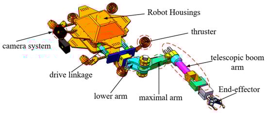
Figure 1.
Overall structural model.
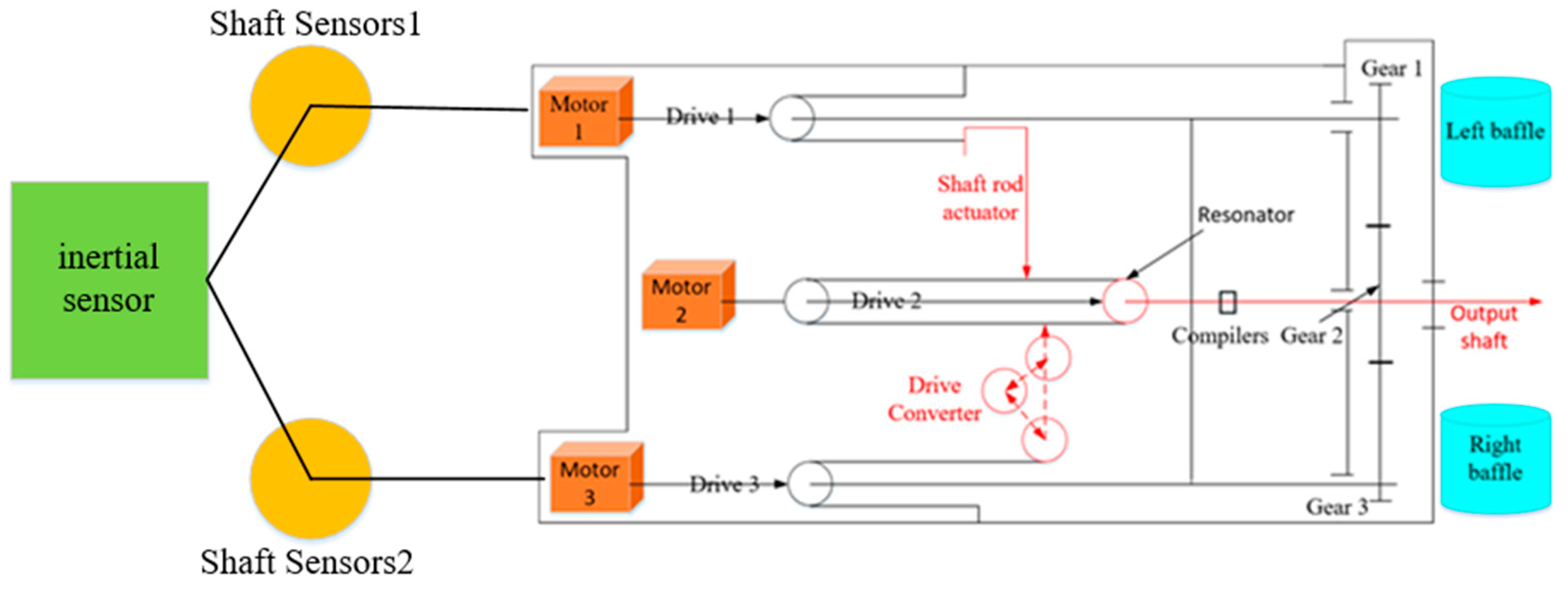
The three-motor drive control designed in this paper includes two modes: common load and gap elimination. The performance of the three-motor servo-driven joints in eliminating backlash lies in the effective control of traditionally generated existential impedance forces. That is, a fixed torque is pre-added to the output shaft, which is finally transferred to the end-effector so that the instantaneous torque generated by the drive converter and the shaft actuator remains engaged with the wheel train. By driving the three drive motors in accordance with the three master wheels together to drive the slave wheels, the entire servo system is in two processes of starting or steering. Three servo motor outputs simultaneously output torque for also to the three gears linkage control, to ensure that the entire drive process is always in a backlash-free control state. The driving principle of the whole telescopic arm motion link is shown in Figure 2, and the structural parameters of the underwater telescopic arm robot are shown in Table 1.
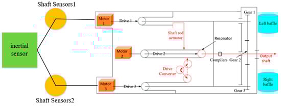
Figure 2.
Working schematic.

Table 1.
Structure parameter table of underwater telescopic arm robot.
2.2. Kinematic Model
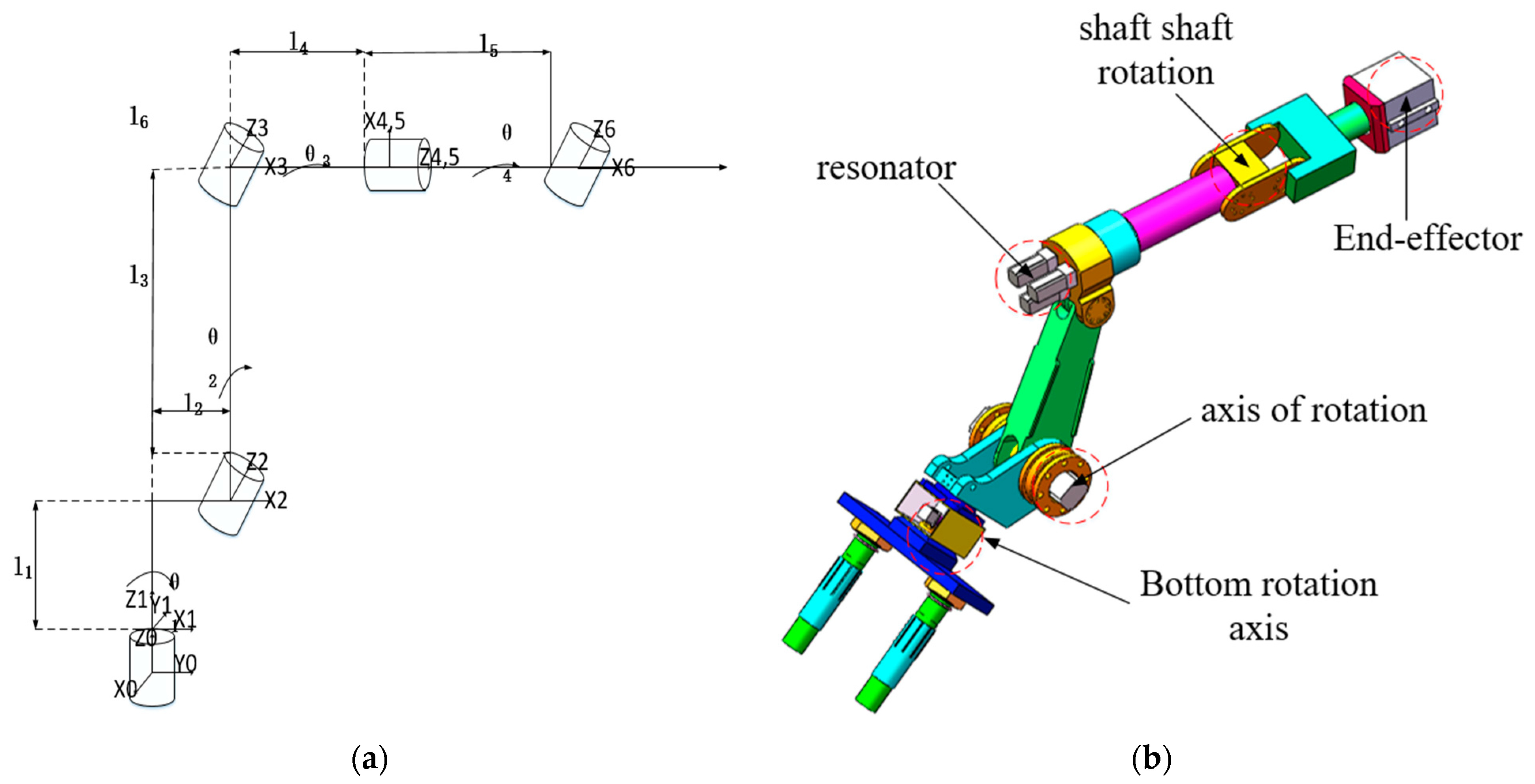
In this paper, the telescopic arm of the designed underwater telescopic arm robot is studied, and its structure is schematically shown in Figure 3b. The telescopic arm shown in Figure 3b is a six-degree-of-freedom robotic arm consisting of six free joints and telescopic rod joints. The three main components of the entire telescopic arm are the big arm in the drive joint, the small arm in the activation pivot, and the telescopic pole arm for search and arrest. The entire arm can be positioned in three dimensions. Three rotating pairs of axle shafts, the bottom shaft and the shaft, respectively, regulate the oscillation of the big arm, the small arm, and the telescopic rod arm joints. The resonator is located at the end of the telescopic boom arm to detect the amplitude of the vibration of the telescopic boom arm approaching the target. The entire robotic arm follows the principle of the positive inverse solution of motion. The D-H parametric method is a method proposed by Denavit and Hartenbery to form the connecting rod into an intrinsic coordinate system. As shown in Figure 3a, one should build the D-H parameter motion axis to establish the motion coordinate system through kinematic analysis, in order to obtain the kinematic positive solution, reflecting the rigor and efficiency of the full-text design.
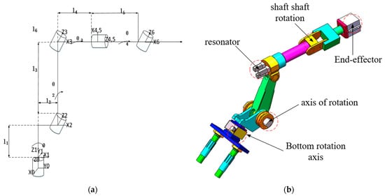
Figure 3.
Schematic diagram of the six-degree-of-freedom telescopic arm motion model: (a) D-H parameter axis; (b) telescopic arm prototype.
The essence of the kinematic positive solution is to solve the position of the telescopic arm end-effector with respect to the base by means of a chi-square transformation matrix based on the given six joint angles input parameter a, parameter , and parameter d. According to the coordinate system established in Figure 3, the obtained improved expression of the chi-square transformation matrix between two adjacent links (i − 1) and (i) is as follows:
By substituting the D-H parameter values in Table 2 as in Equation (1), the end-effector poses can be obtained:
Table 2.
Underwater robot arm D-H parameter list.
The parameters in the formula are obtained:
In the above equation:, the homogeneous kinematic inverse solution is to solve for the six joint angles of the telescopic arm at a given end-effector attitude.
3. Optimal Trajectory Planning with the Improved Dung Beetle Algorithm
3.1. A 5-5-5 Polynomial Trajectory Planning Method Based on the Dung Beetle Algorithm
In view of the specificity of the 5-5-5 polynomial trajectory planning, it is necessary to ensure that the underwater telescopic arm in the whole process of movement impact at the beginning and end of the 0, reducing unnecessary collision interference. The entire underwater telescopic arm completes its trajectory by first ensuring that the end-effector moves from its initial position and then reaches a designated position to perform the task of capturing the underwater target. The entire movement of the underwater telescopic boom needs to be continuous and uninterrupted to improve search efficiency. The underwater telescopic boom search for a target can be divided into three stages: the target discovery phase, a phase where the end-effector makes slow contact with the target, and the underwater telescopic arm position adjustment phase. The initial point of the underwater telescopic arm in Cartesian space is set as Q, the distance from the telescopic arm approaching the target position is set as T, the intermediate positions are distributed and , the parameters of each joint are applied to the 5-5-5 polynomial trajectory planning of the robot arm by kinematic analysis, and the expressions are as follows:
In the formula, in the three phases of the operation of the underwater telescopic arm are , , and ; , , and are the trajectory curve of the underwater telescopic arm in contact with the target; the coefficients to be determined are set to , , and .
In order to constrain the underwater telescopic arm to always follow the smooth, high-order principle during contact with the target, zeroing the individual velocities, accelerations, and accelerations at the starting point of the underwater telescopic arm and the target termination point is handled with the following expression:
where, the angles of each joint of the telescopic arm at four different positions are shown by , , , and ; and , , and are replicated into MATLAB according to the principle of mechanical arm continuity.
3.2. Tent Chaotic Dung Beetle Search Algorithm
Underwater telescopic arm robots can be interfered with by floating biological obstacles when performing target capture operations underwater. This leads to the problem that the trajectory planning is not clear, and the target capture route is not optimized. To address this class of problems, this paper designs the chaos-tent type dung beetle algorithm applied to the trajectory planning problem of an underwater telescopic arm robot. This algorithm has a unique sharp search capability and an extremely strong obstacle avoidance performance for target tracking. Designing the insertion of chaotic-Tent mapping dung beetle algorithm is undertaken to increase the global search of the optimal solution and further solve the optimal solution of the telescopic arm under multiple iterations. The efficiency of the chaos-Tent mapping dung beetle algorithm applied to motion planning for an underwater telescopic arm robot is demonstrated.
3.2.1. Dung Beetle Algorithm
The dung beetle is one of nature’s most sensitive peripherals, able to both map its prey and plan optimal trajectory routes for itself to avoid predators. The four main journeys of the dung beetle’s specialized form of foraging are rolling, reproduction, foraging, and stealing. The dung beetle algorithm we designed for this particular form is divided into four algorithmic journeys: the initial population phase, the population reproduction phase, the prey finding search phase, and the prey catching phase. We form an obstacle-free optimal trajectory route for the prey target search.
Initial population stage: The initial population in the initial update position will navigate itself to a position considering the intensity of the sun’s light source. If the location is found to be in the no obstacle mode, the position of the dung beetle is updated as follows:
In the above formula, is represents the update position of the i-th dung beetle in the initial population in the without obstacle mode at the t-th iteration. represents the number of iterations, which is the deflection coefficient and the interval is (0, 1). is the natural coefficient. It can be assigned 1 or −1, where 1 represents normal navigation, −1 represents abnormal navigation, represents the worst position of the iterative population, and shows the influence of light intensity navigation.
If the dung beetle encounters an obstacle and cannot move forward, it is like the following Figure 4. If the underwater telescopic arm robot needs to change the direction of obstacle avoidance, imitate the dung beetle rolling the dung ball, and move to the new rolling direction, the interval is .
Figure 4.
Simulating dung beetle steering.
The dung beetle establishes a new trajectory in the case of effective obstacle avoidance. The updated position formula at this time is as follows:
Propagation stage: After the initial population stage, dung beetles need to lay hidden eggs in order to hunt more prey and roll to safety, thus reproducing more individuals to increase the likelihood of prey. It also makes an effort to iterate the optimal individual. At this point, the spawning area and the formation iteration of the individual position formula update positions as follows:
In the above formula, represents the upper and lower limits of the excellent individuals that reproduce and produce dung beetles, is the best position for global search, , Y is the maximum number of iterations, m and n are the independent parameters of the global search, and are the positions of the i-th newborn body in the i-th iteration cycle.
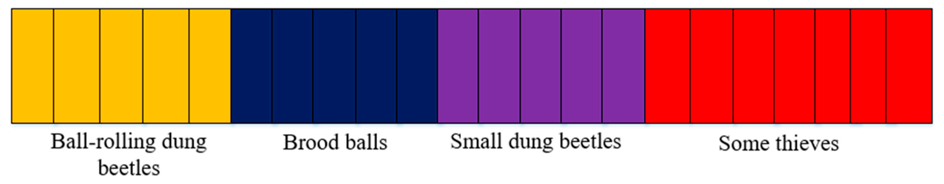
Population search stage: in the breeding stage of the high quality dung beetles, they will implement the pre-population stage of prey as shown in Figure 5 to ensure that the prey’s excellence is scrutinized, and at this time the dung beetles will be renewed in the following positions:
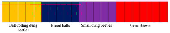
Figure 5.
Rules for the delimitation of stocks.
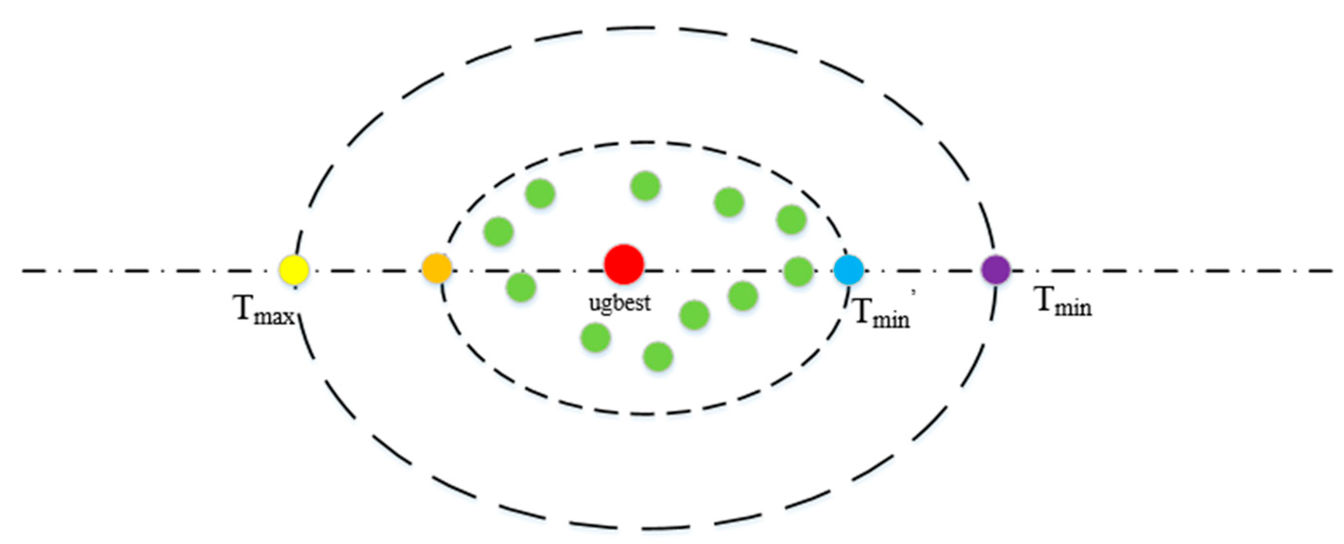
The stage of capturing prey: Dung beetles estimate the linear distance ratio between themselves and their prey during the feeding phase so that they can strike effectively at their prey, attracting prey to the best feeding areas and relying on its unique striking distance and striking speed to accurately capture prey. The area where the prey is confined by the dung beetle is shown in Figure 6, and the updated positions of the prey and the dung beetle are as follows:
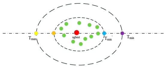
Figure 6.
Prey boundaries.
As shown in the above figure, and are the boundary of prey. and are the upper and lower limit of the dung beetle’s search for the prey, is the best position for the dung beetle to capture the prey, and the optimal route for the underwater telescopic arm robot to capture the target.
3.2.2. Tent Chaotic Sequence
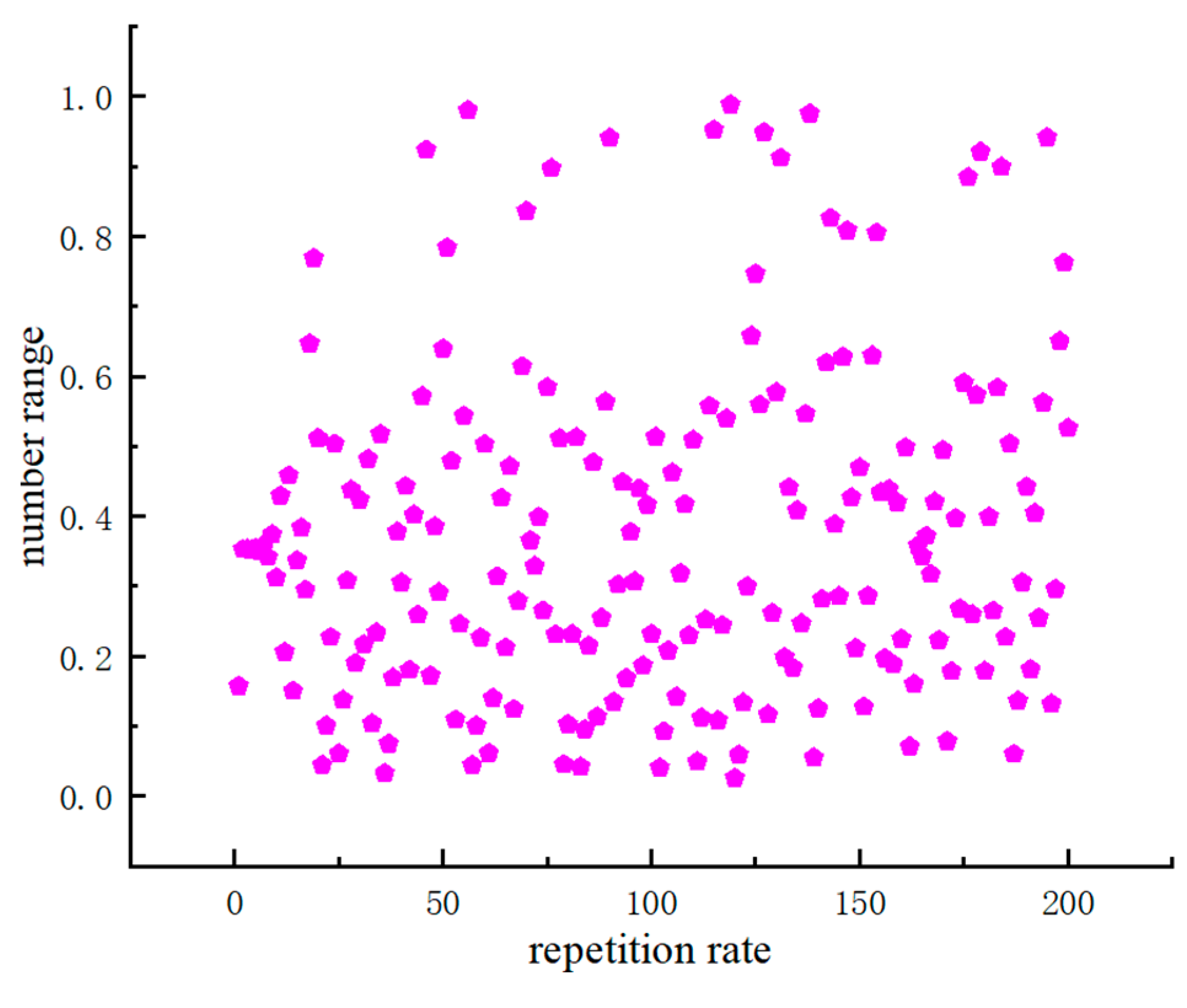
Given that the dung beetle algorithm may limit the trajectory optimum to certain limitations, it is not possible to take a global larger scale approach. Therefore, in this paper, we design an improved dung beetle algorithm to introduce Tent chaos into the dung beetle algorithm so as to realize the uniformity of the whole global search and speed up the search. Figure 7 shows the distribution of Tent’s chaotic sequences. The improved dung beetle algorithm designed in this paper fully utilizes Tent’s uniformly distributed chaotic sequences. An effective initiative to reduce the impact of local optimal bias surface optimization and enhance global optimization search to further reveal the efficiency of the improved dung beetle algorithm.
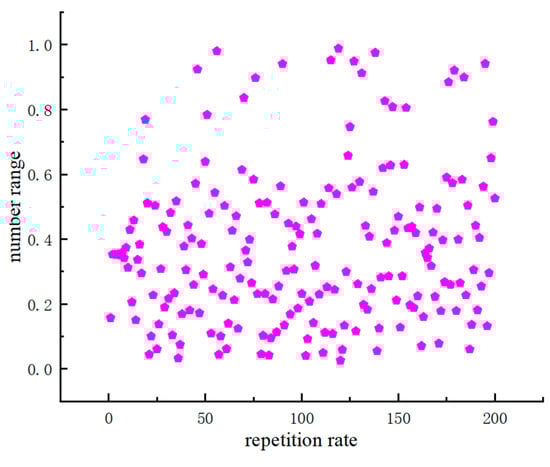
Figure 7.
Tent chaotic sequence distribution map.
The expression of the Tent chaotic map is as follows:
In the above formula, e represents the distribution probability of chaotic sequence. When e belongs to the interval , the sequence does not show uniform distribution at this time. At this time, , the whole sequence shows uniform distribution. Different parameters form a distribution density with a certain approximate consistency. At this time, the search for the optimal trajectory is global.
3.2.3. MDBO Algorithm Steps
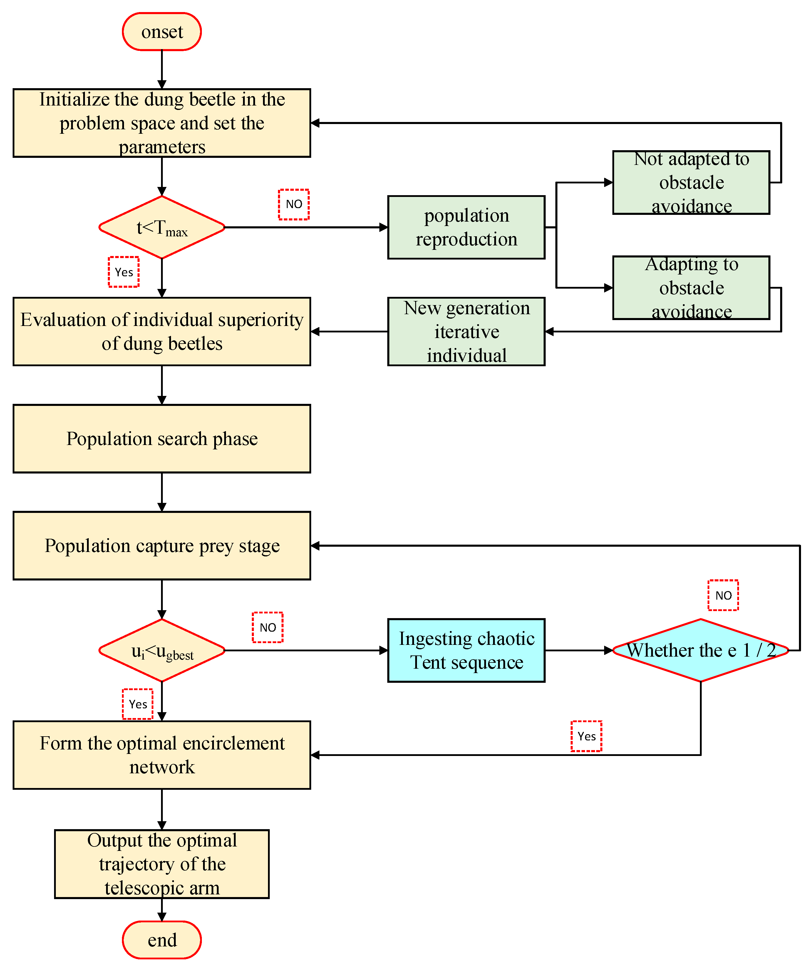
The steps of MDBO dung beetle trajectory optimization algorithm are shown in Figure 8. The steps are as Algorithm 1:
| Algorithm 1: MDBO implementation steps |
| Step 1: Use kinematics to build a telescopic arm model and solve the parameter values to establish a 5-5-5 polynomial trajectory planning path. Step 2: Initialize the original population of dung beetle in the problem space and set the parameters. Step 3: Eliminate some of the native populations according to the winning strategy, and give priority to the selection of the new generation of iterative individuals who adapt to obstacle avoidance in population reproduction. Step 4: The iterative evaluation of excellent individuals for population search and population capture prey stage to find the optimal prey direction. Step 5: Ingest a chaotic Tent sequence for global search to form the optimal bounding network. Step 6: Find the optimal individual and output the optimal trajectory of the telescopic arm. |
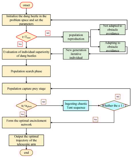
Figure 8.
MDBO algorithm flow.
4. Simulation and Analysis
4.1. Simulation Environment Settings
In this paper, the proposed improved dung beetle algorithm is simulated and calibrated using the underwater telescopic arm robot motion model in Figure 3, combined with the D-H parameter motion 5-5-5 polynomial trajectory planning in Table 2 in three interspersed time values. , setting the population size of the improved dung beetle algorithm. is the number of variables. is the scaling factor. The maximum number of iterations is 100, and the test equipment is an Intel (R) Core (TM) i5-13400FCPU @ 2.40GHZ, 16GBRAM, 3060Ti, and 64-bit Windows 10 Professional version. The software MATLAB2022 b is used for simulation experiments. For each function, multiple independent experimental verifications are performed, and the average value and standard deviation of the experiments are recorded to evaluate the performance of the algorithm.
4.2. Validate the Algorithm by Testing Functions
There are eight classical unconstrained optimization functions, including single-peak functions (–) and multi-peak functions (–). The detailed information of the test function is shown in Table 3, the optimal solution in the single-peak function can evaluate the algorithm’s convergence speed and the development ability. The multi-peak function applies the global solution to increase the searching ability of global objectivity, and the multi-peak function applies the global solution to increase the searching ability of global objectivity.
Table 3.
Test function classification table.
In order to verify the efficiency and superiority of the MDBO algorithm to adapt to and apply the telescopic arm obstacle avoidance and motion planning different from other algorithms, this paper sets the initial population number of particle swarm optimization (PSO), differential evolution algorithm (EA), and sparrow algorithm (SSA) to improve the safety threshold. The particle swarm optimization algorithm is an evolutionary computational technique derived from the study of the behavior of birds feeding in flocks. Its basic idea is to find the optimal solution through collaboration and information sharing among individuals in a group. The sparrow search algorithm mainly utilizes this biological property of sparrows for iterative optimization search. The problem to be solved by the genetic algorithm is modeled as a process of biological evolution. It generates the next generation of solutions through operations such as replication, crossover, and mutation, and gradually eliminates solutions with low fitness function values, thereby adding solutions with high fitness function values. In this paper, we set the initial number of all algorithm populations to 100 and the maximum number of iterations to 500. By analyzing the above eight test functions, the mean and standard deviation of the five algorithms were calculated, and the performance of the algorithms was evaluated through the columns in Table 4.
Table 4.
Comparison of experimental results between the MDBO and the basic algorithm.
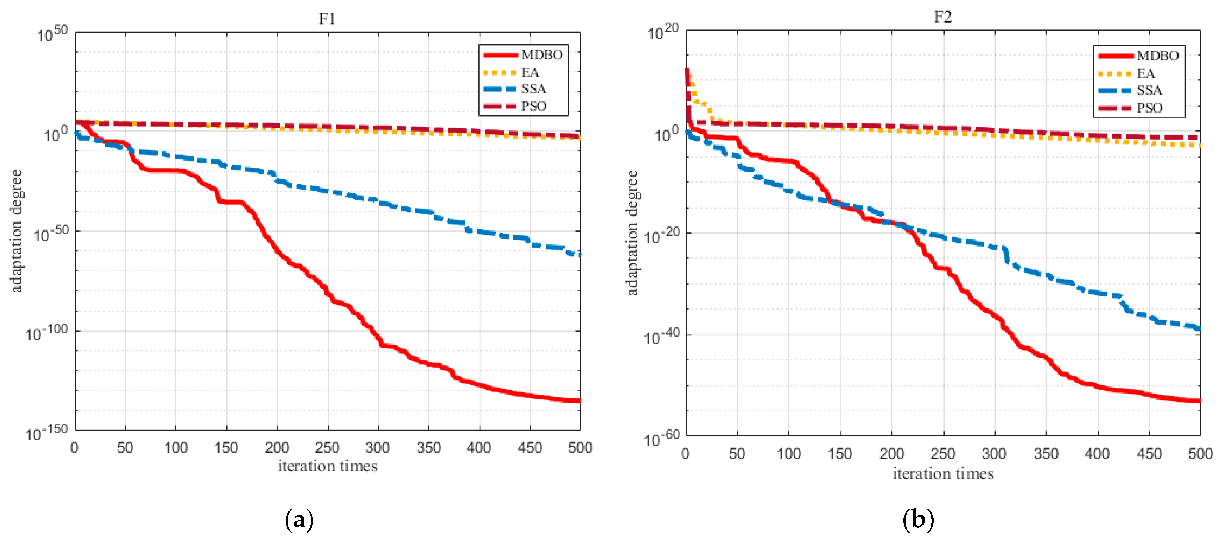
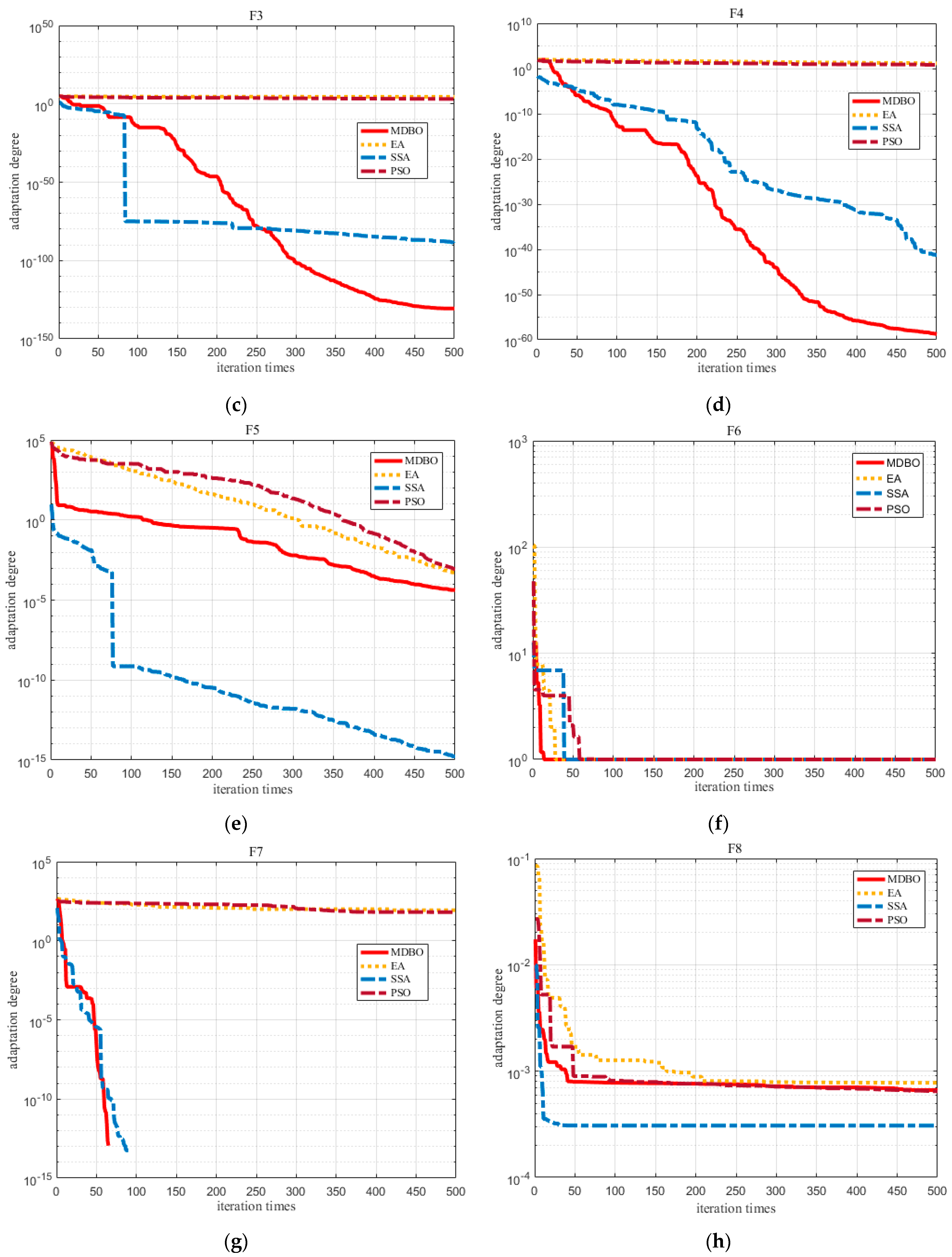
According to the analysis shown in Table 4, it is observed that the average value of MDBO is theoretically optimal for unimodal functions –. The standard deviation is close to 0. In the unimodal function , the average value of the MDBO algorithm is more advanced, and the standard deviation is also maintained at 0. It can be inferred that the MDBO algorithm has stronger insight and search ability in the optimization test process. In the test verification of the multimodal function –, the average value of the MDBO algorithm is still close to the theoretical optimal value and the standard deviation is 0. It shows that the optimization results of multiple test experiments are consistent. Therefore, the MDBO algorithm which we designed has a strong optimization ability and adaptability, and we can achieve local optimization of multimodal functions at multiple extreme points. The test convergence curve of – is shown in Figure 9.
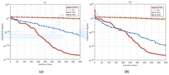
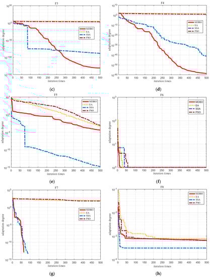
Figure 9.
Comparison of convergence curves of each algorithm of test function: (a) F1; (b) F2; (c) F3; (d) F4; (e) F5; (f) F6; (g) F7; (h) F8.
4.3. MDBO Solves the Problem of Time-Optimal Trajectory Planning
Figure 10 shows the convergence curves of the ordinary dung beetle algorithm (DBO) and the improved dung beetle algorithm (MDBO). Tested in various test functions, MDBO always shows higher optimization accuracy than DBO, and maintains the stability of the entire motion planning stage. The improved dung beetle algorithm has stronger fitness and more obvious convergence speed than the original ordinary dung beetle algorithm. The overall curve is smooth without fluctuation, which verifies the efficiency of the improved dung beetle algorithm proposed in this paper applied to the telescopic arm trajectory optimization and obstacle avoidance.
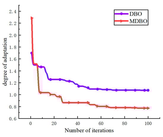
Figure 10.
Convergence curve of the fitness function.
4.3.1. Adaptation of the Algorithms to Telescopic Arm Trajectory Planning
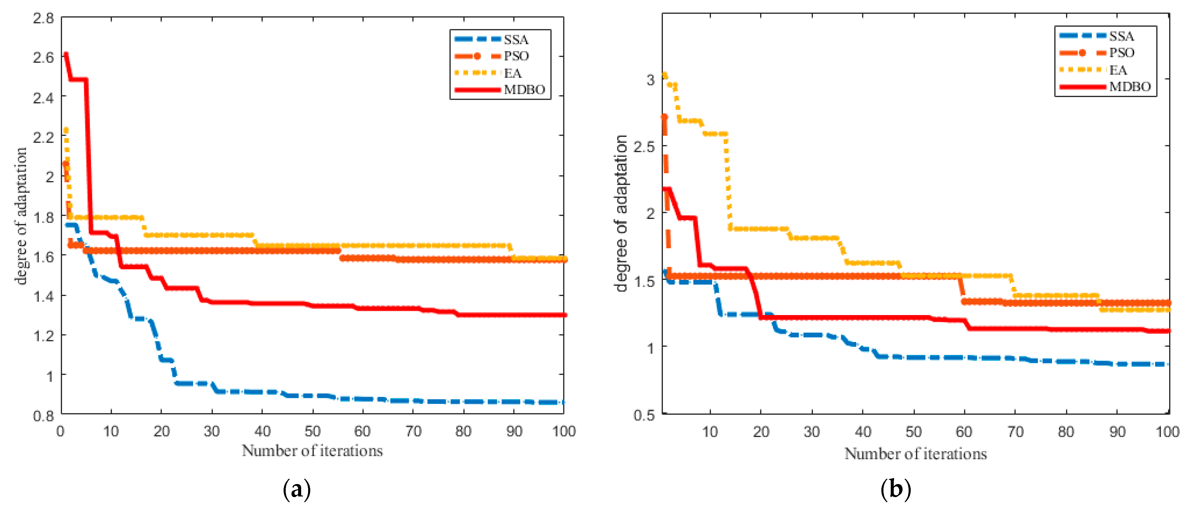
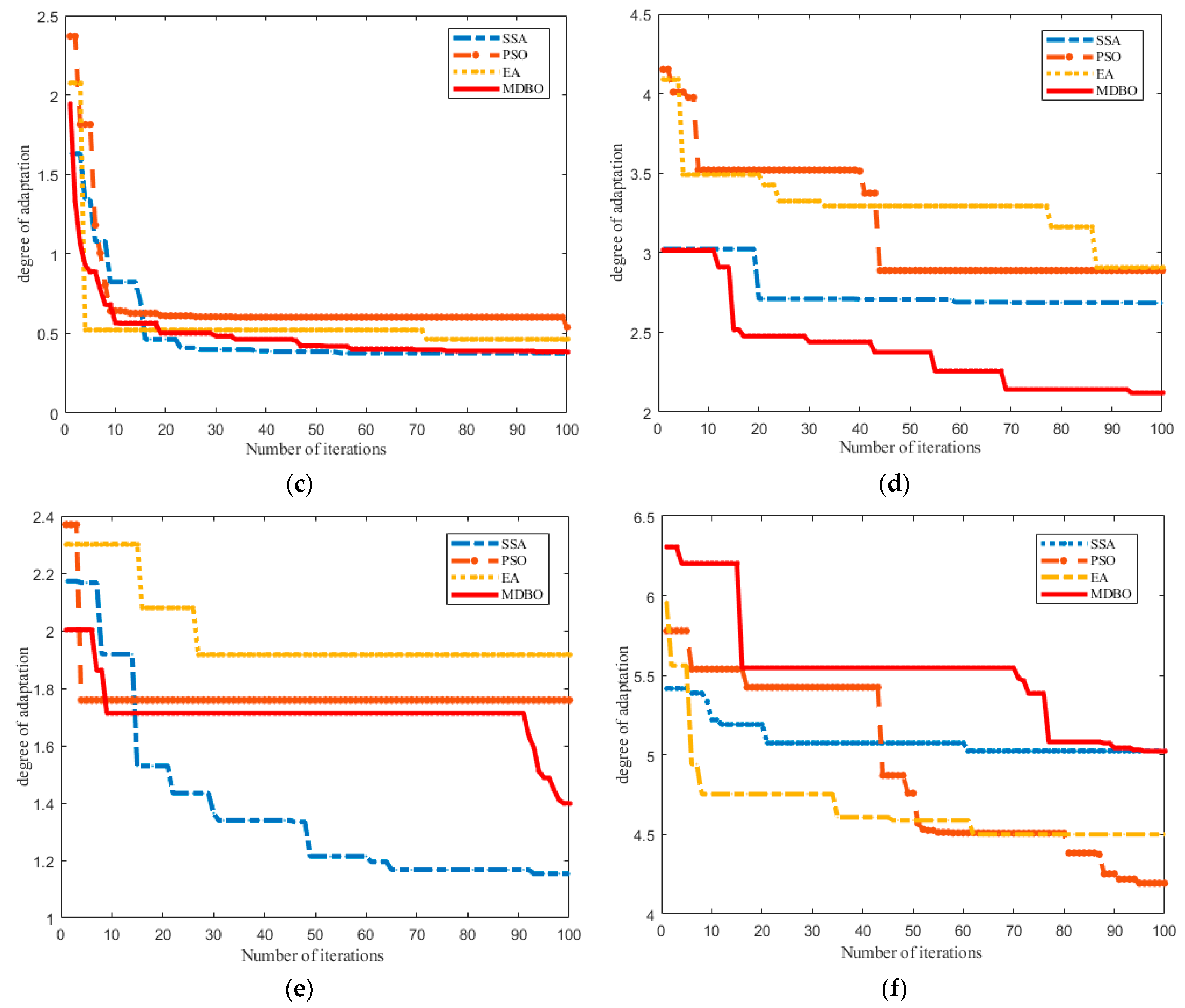
In order to further clarify the performance difference between the MDBO algorithm proposed in this study and other algorithms (such as PSO, EA, SSA), this paper sets the initial population number of particle swarm optimization (PSO), differential evolution algorithm (EA), and sparrow algorithm (SSA). Consistent improvements to the safety threshold, unification of the maximum number of iterations to 100, and the fitness curves of the six joints of the telescopic arm for different algorithms are shown in Figure 11.
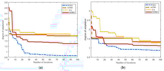
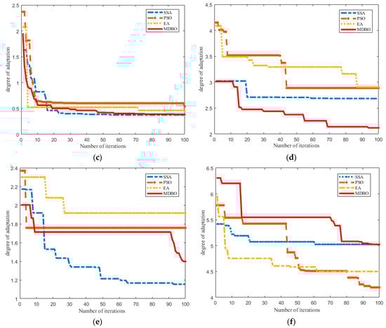
Figure 11.
Adaptation value curve for comparison algorithms for motion planning of telescopic arm: (a) Joint 1; (b) Joint 2; (c) Joint 3; (d) Joint 4; (e) Joint 5; (f) Joint 6.
The simulation results show that the convergence performance of the MDBO algorithm to find the optimal trajectory is better than that of other algorithms, and the adaptive range is wide. The six joints of the telescopic arm have strong adaptability to the MDBO motion planning route, which further ensures the accuracy of the trajectory optimization path and reflects the effectiveness of the MDBO algorithm applied to the path planning of the telescopic arm.
4.3.2. Comparison of the Results before and after Optimization
In order to verify the effectiveness and superiority of the improved dung beetle algorithm applied to the telescopic arm to reduce obstacle avoidance and path optimization, the trajectory tracking of the same target is carried out. The joint parameters of the manipulator before and after optimization are shown in Figure 12 and Figure 13.
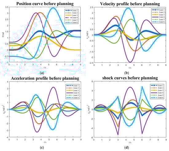
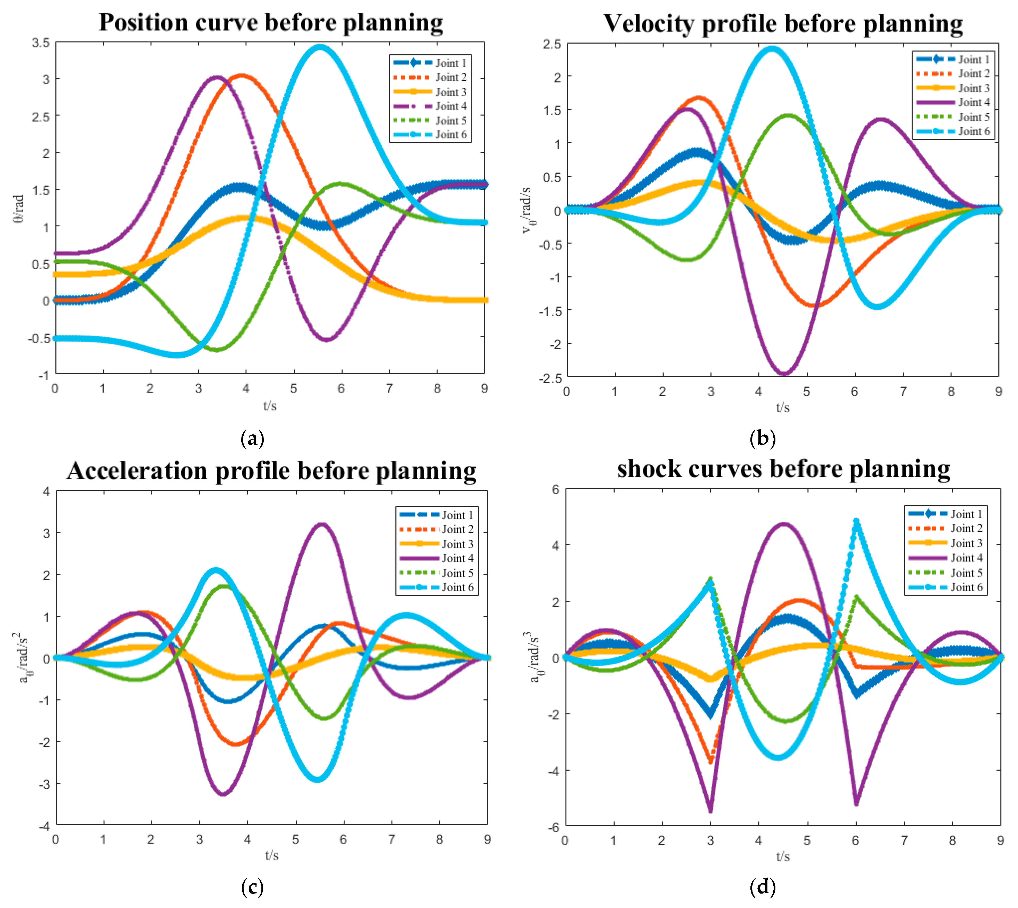
Figure 12.
Telescopic arm parameters before optimization: (a) position; (b) velocity; (c) acceleration; (d) shock.

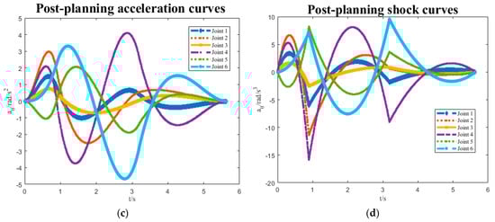
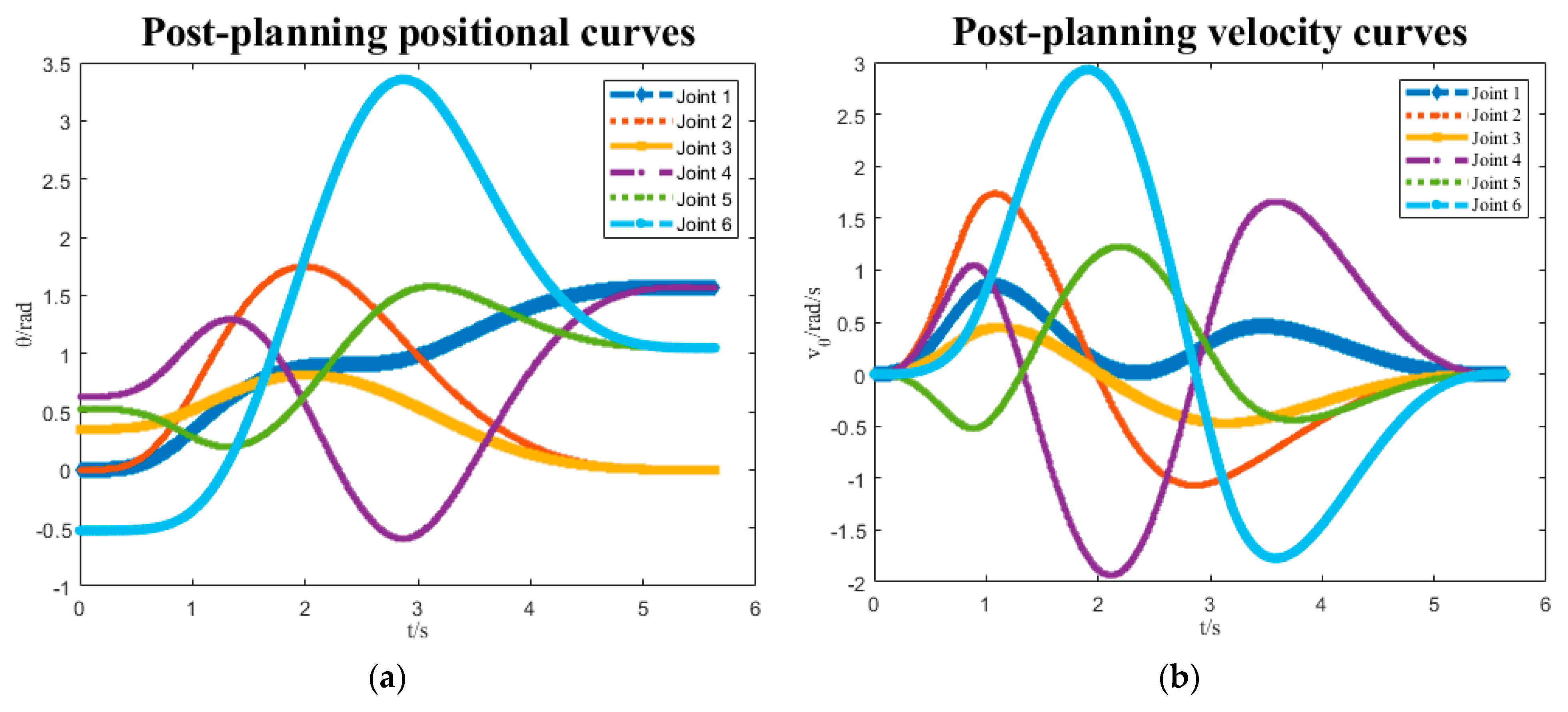
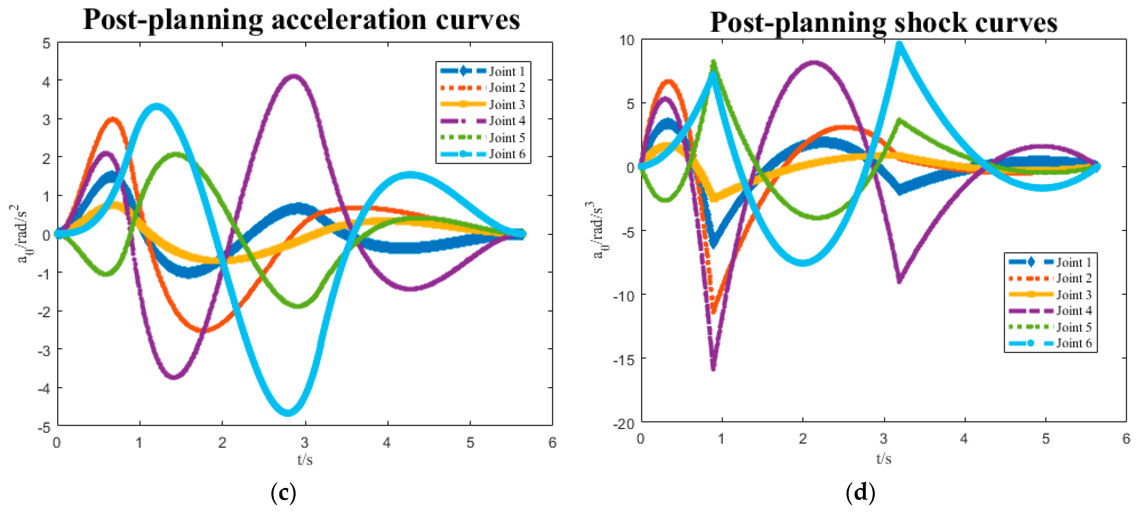
Figure 13.
Optimized telescopic arm parameters: (a) position; (b) velocity; (c) acceleration; (d) shock.
The simulation results comparing the changes in the position, velocity, acceleration, and impact parameters of the telescopic arm before and after optimization in are shown in Figure 12 and Figure 13. The trajectory route planned by MDBO is more convenient. The trajectory time of the telescopic arm to complete the capture of the target is shortened from 9 s before optimization to 6 s after optimization. The impact rate is reduced by nearly 30%. This shows that the MDBO algorithm avoids the obstacles of motion planning to a certain extent, increases the obstacle avoidance performance, and saves the operation planning time. The optimized velocity, acceleration, position, and impact curves are smooth, and do not produce large mutations, which fully reflects the effectiveness of the MDBO algorithm. Table 5 shows the optimized test results.
Table 5.
Experimental results before and after optimization.
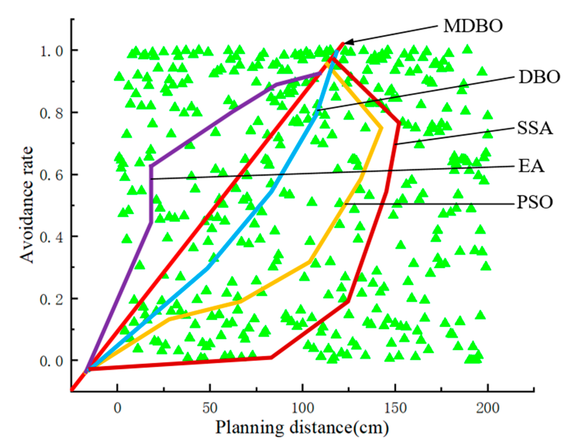
Based on the five algorithms, the telescopic arm trajectory completed under the planning distance of 200 cm is shown in Figure 14. The MDBO algorithm has the shortest optimal trajectory planning path, and the obstacle avoidance efficiency is better than other algorithms, which fully reflects the comprehensiveness of the MDBO algorithm.
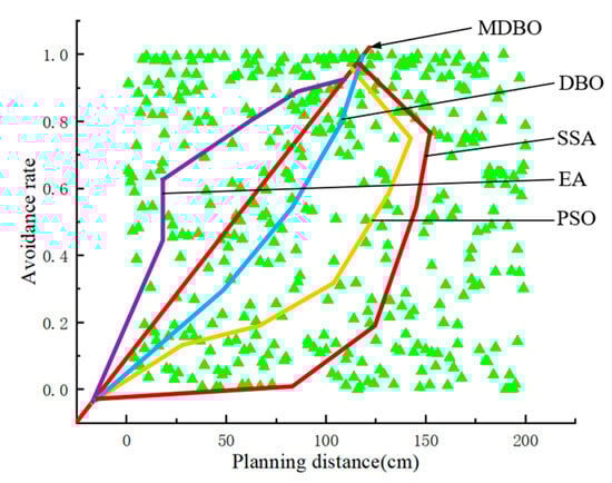
Figure 14.
The path comparison after planning.
5. Virtual Prototype Experiment
To verify the practical effect of the MDBO algorithm applied to an underwater telescopic arm robot for searching and grasping underwater targets, we examined the application of the MDBO algorithm to motion planning and effective obstacle avoidance of an underwater telescopic arm, by taking experiments comparing normal drive and MDBO drive conditions.
5.1. Experimental Environment Settings
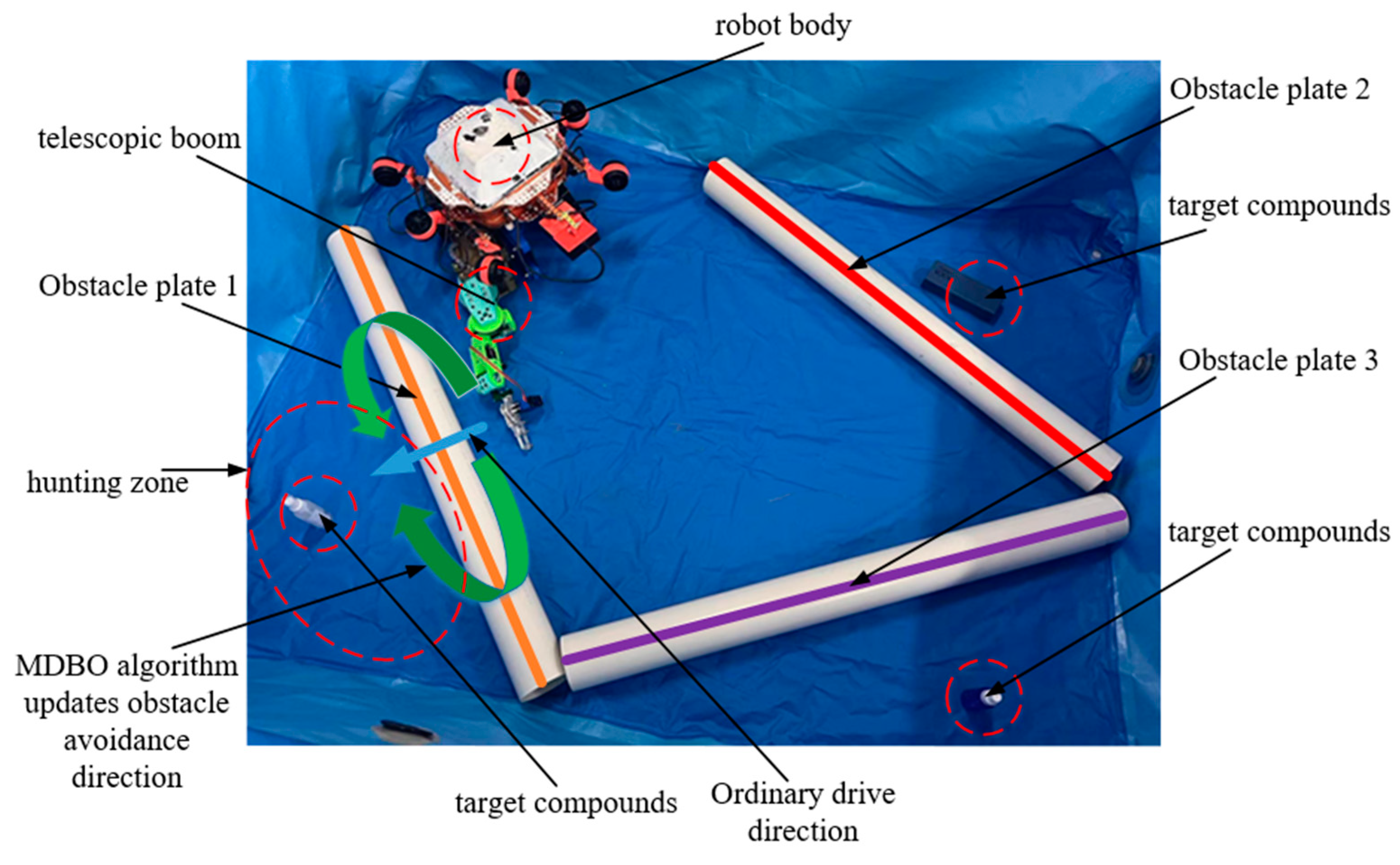
In this paper, the underwater target grabbing test is designed to use the propulsion force of the underwater robot’s own servo motors, thereby sending the underwater telescopic arm robot closer to the target to reach the telescopic arm’s executable search range. The MDBO algorithm is applied to activate the telescopic arm input for the input program and the output to control the telescopic arm to execute the capture command. By setting up obstacle plates 1, 2, 3 to increase the obstacles for the trajectory planning of the telescopic arm, and placing the target at the designated location for the underwater experiment, the setup of the underwater experiment environment is shown in Figure 15. This experimental environment is a preset environment, and the whole state belongs to the waterless state.

Figure 15.
Underwater experimental environment.
5.2. MDBO Underwater Test Model
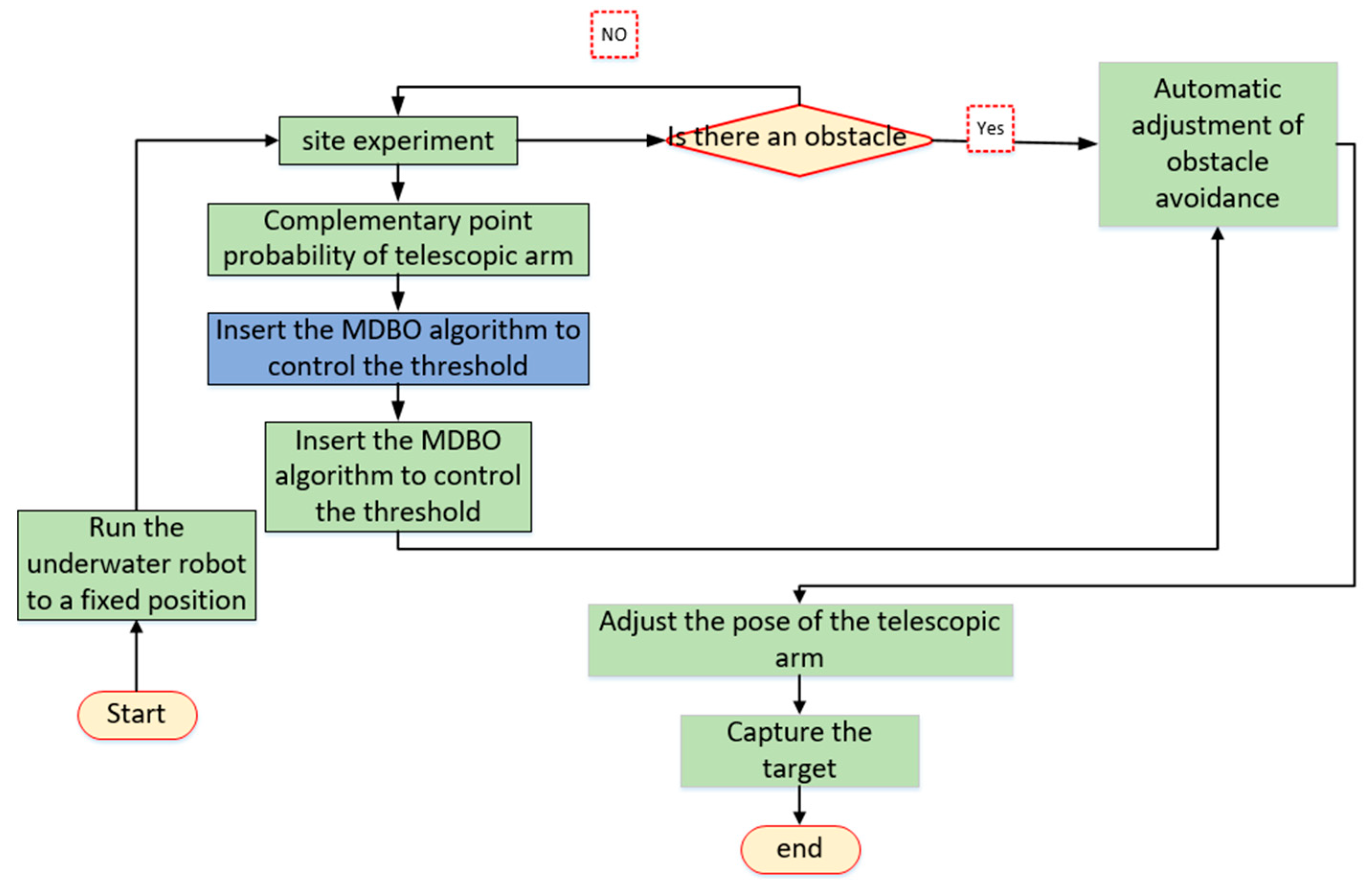
In view of the particularity of the underwater environment, we set the water depth to 18 cm to ensure that the speed of the water and external interference is negligible. We have taken pilot tests on the telescopic arm input many times first. Preliminary data on the probability of a retractable arm avoiding a patch point indicate effective regulation by inserting the MDBO algorithm to form the entire effective telescopic arm to search the trajectory obstacle blind zone (Algorithm 2). Thus, automatic and effective obstacle avoidance is realized, and the obstacle avoidance flowchart of the experimental algorithm is shown in Figure 16.
| Algorithm 2: MDBO Execution steps |
| Step 1: Drive the underwater robot to a fixed position through the STM-32 single-chip microcomputer. Step 2: Drive the telescopic arm to check the obstacle detection point and perform contact blind probability feedback. Step 3: According to the probability of blind touch, the MDBO algorithm is introduced to control the threshold, perform the pose transformation of the manipulator, and form the self-avoidance obstacle. Step 4: Form the telescopic arm motion planning path. Step 5: Execute the capture command to capture the target |

Figure 16.
Underwater test obstacle avoidance flow chart.
5.3. Test Results
Based on the underwater test environment conditions, we set the total time to complete the entire motion planning and capture the target to not exceed 10,000 ms. The water flow of the telescopic arm and the underwater robot throughout the underwater test is a hydrostatic flow state with reducing human interference. In order to better meet the requirements of the test, we placed the inertial navigation sensor at the end of the telescopic arm, and monitored the variable parameters of the telescopic arm to complete the trajectory planning in real time through the virtual prototype. The introduction of the Tent idea before the formal experiments began to let the telescopic arm to form a number of touch blindness tests to ensure that the later actual experiments to improve the rate of obstacle avoidance. Figure 17 reflects the pre-point blindness probability before the experiment.
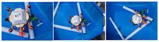
Figure 17.
Pre-point touch blindness experiment.
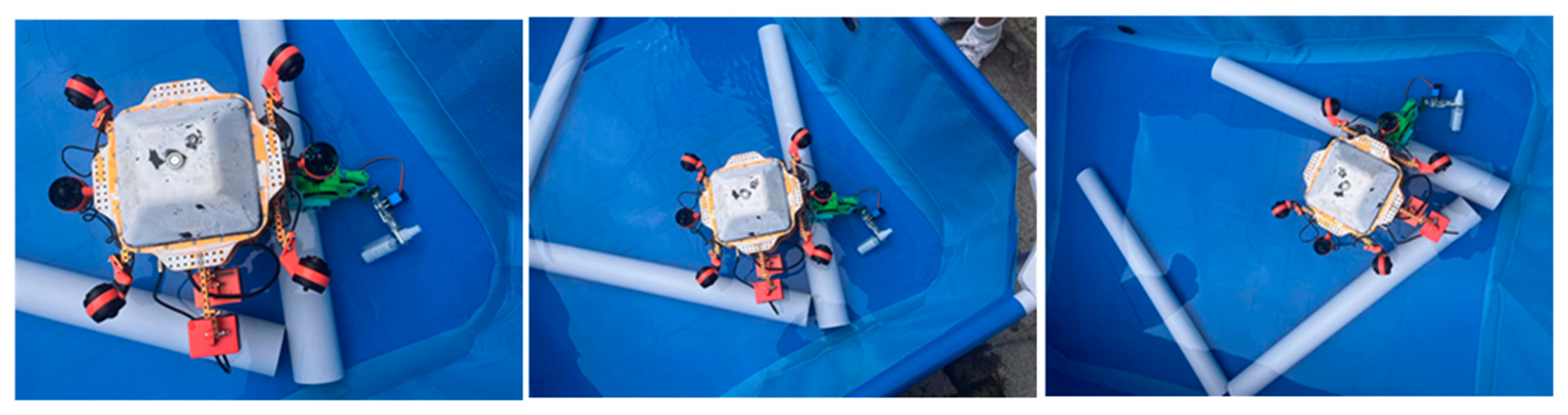
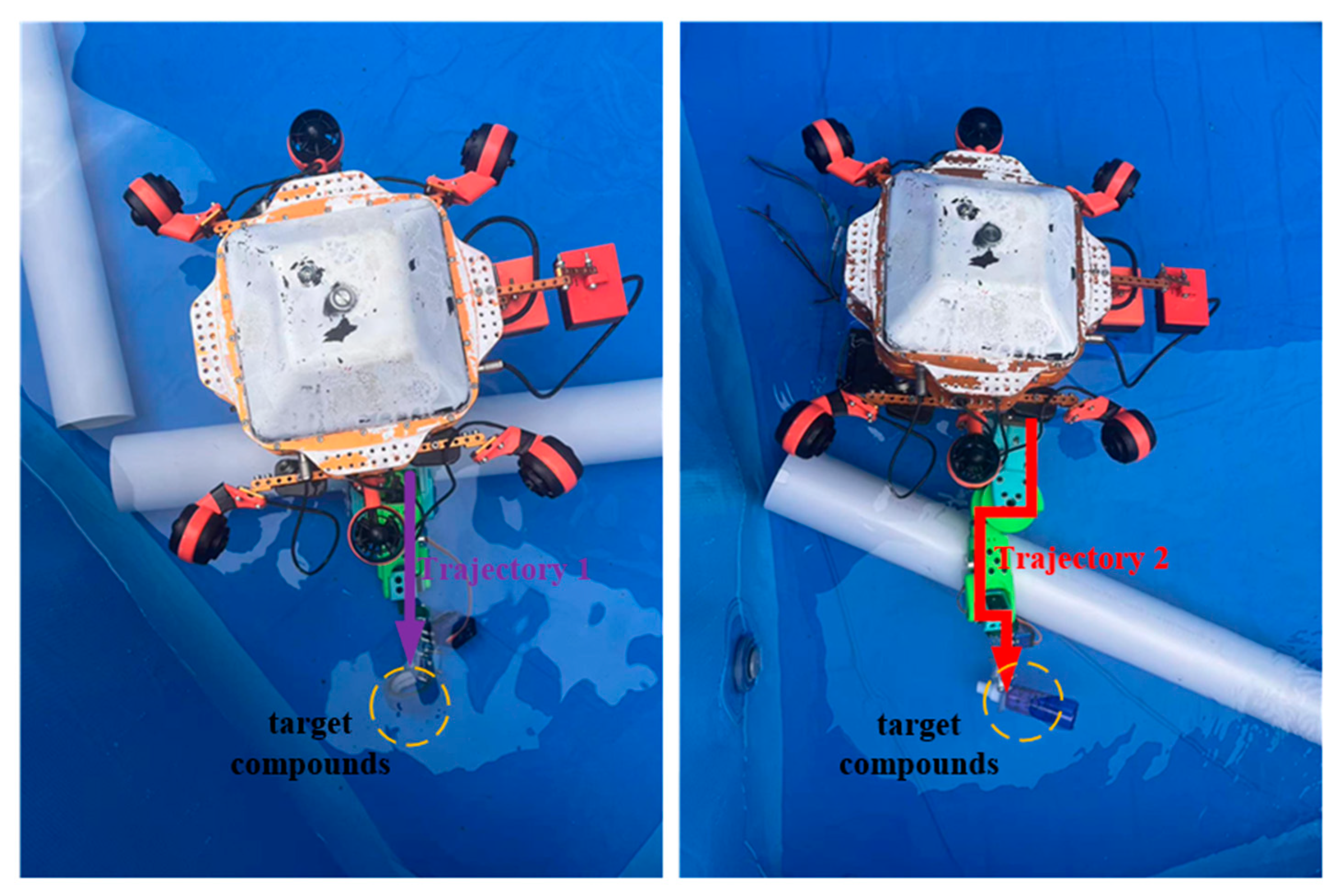
In this underwater telescopic arm motion planning experiment, we designed a comparative experiment to more clearly reflect the performance advantages of the MDBO algorithm. The one in the left figure of Figure 18 was used to implement the ordinary drive to capture the target, and the other was to perform the MDBO algorithm capture according to the steps of Algorithm 2. In the process of completing the unified capture of the target, according to the inertial navigation sensor, we collected 10,000 data samples of the ordinary drive and 5843 data samples of the MDBO for testing the accuracy of the data. Figure 18 reflects the trajectory test diagram under the two methods of the telescopic arm. Figure 19 reflects the data acquisition diagram after the completion of the two tests.
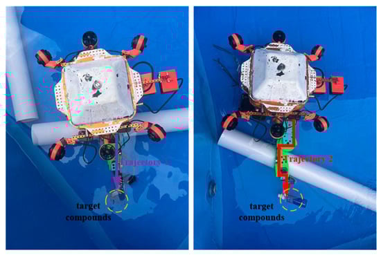
Figure 18.
Experimental diagram of telescopic arm trajectory.
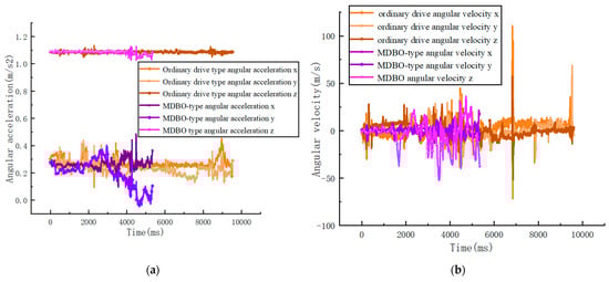
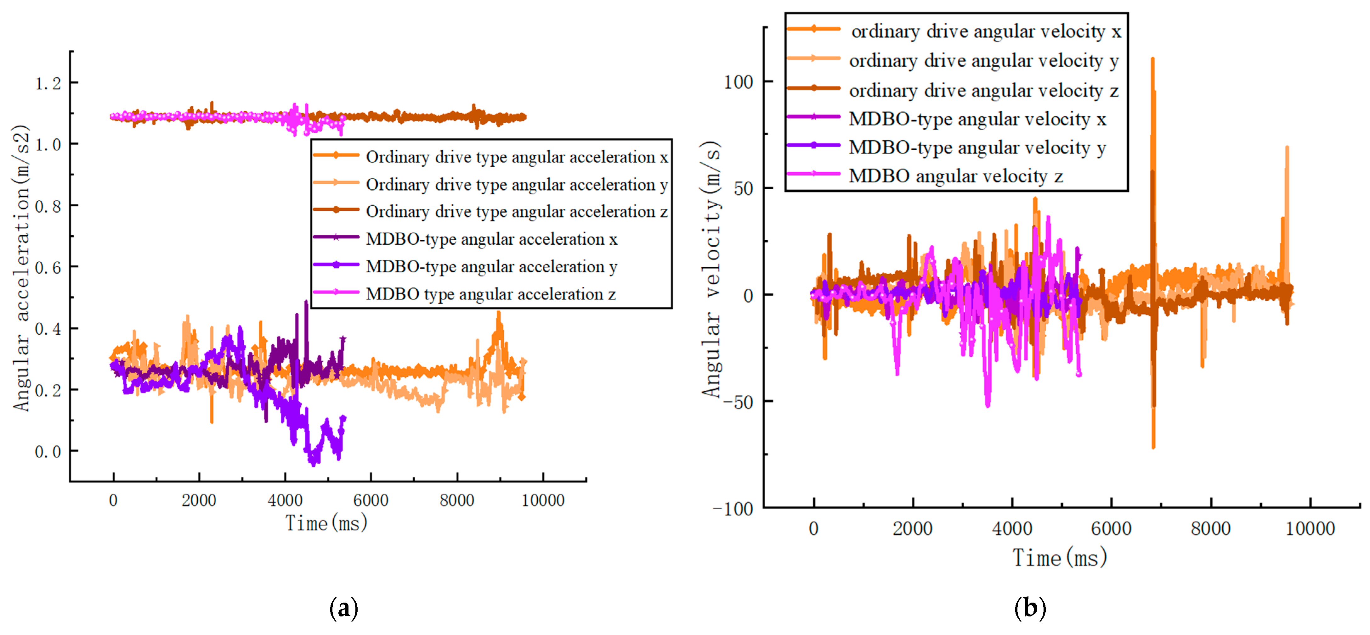
Figure 19.
Comparison effect diagram of catching test. (a) angular acceleration; (b) angular velocity.
The simulation results in Figure 19a,b show that that the direct-driven telescopic arm with the unimproved algorithm can jump over the collision plate and grab the target by its own impedance. The curve remains smooth in the early stages, but mutates in the later stages, when it encounters an obstacle that it cannot avoid. Compared to the ordinary drive, the telescopic arm applied by MDBO algorithm can expand the search range according to the probability of collision, so as to form the optimal trajectory planning route for obstacle avoidance (Table 6). The time before planning is 9.876 s, and the time after planning is 5.843 s. It is obvious from Figure 19 that the obstacle avoidance trajectory time under the planning of MDBO algorithm is significantly reduced by 40%. The collision rate before planning is 36.2%, and the collision rate after planning is 13.2%. The number of collisions was reduced from twice in the original to 0 times after planning. The smoothing of the curve did not produce large abrupt changes, and the overall trend remained steady. The efficiency of the MDBO algorithm applied to the telescopic arm to capture the target is further revealed.
Table 6.
Experimental results.
6. Conclusions
In this paper, an MDBO algorithm is proposed to be applied to the trajectory optimal planning and effective obstacle avoidance of an underwater telescopic arm robot, against the disadvantage that the DBO algorithm is unable to jump out of the local optimum and the number of iterative quality populations is small. The idea of Tent chaotic mapping is also introduced to improve the algorithm’s global search capability and filter the inferior iterative populations. In order to solve the disadvantage of low accuracy of time-forming trajectory routes, a hybrid polynomial interpolation algorithm is used. Combining the 5-5-5 polynomial trajectory interpolation with the MDBO algorithm, the algorithm designed in this paper converges at the global optimum. The simulation results demonstrate the efficiency and practicality of the MDBO algorithm. Compared with other algorithms, the MDBO algorithm designed in this paper has better obstacle avoidance performance, better convergence performance, and relatively high convergence speed. The trajectory planning time for each joint to complete the capture of the target object improved from 9 s before planning to 5 s after planning, and the stability also improved.
In addition, we applied the MDBO algorithm to the telescopic boom underwater test. By forming a pilot threshold through Tent idea, the MDBO algorithm motion planning for path obstacle avoidance is good and the motion planning time is reduced by 30%. Future research will extend MDBO to address vibration in robotic underwater testing.
Author Contributions
Conceptualization, H.J. (Haitao Ji) and H.J. (Huawei Jin); methodology, H.J. (Haitao Ji); software, H.J. (Haitao Ji); validation, H.J. (Haitao Ji), H.J. (Huawei Jin) and F.Y.; formal analysis, H.J. (Haitao Ji); investigation, H.J. (Haitao Ji); resources, F.Y.; data curation, H.J. (Haitao Ji); writing—original draft preparation, H.J. (Haitao Ji); writing—review and editing, H.J. (Huawei Jin); visualization, F.Y.; supervision, H.J. (Haitao Ji); project administration, F.Y.; funding acquisition, H.J. (Haitao Ji). All authors have read and agreed to the published version of the manuscript.
Funding
This work was supported by the National Foundation of China (Grant NO.: 51904009), and the Open Fund of Anhui Key Laboratory of Mine Intelligent Equipment and Technology, Anhui University of Science and Technology (ZKSYS202102). The national key research and development plan “Coal mine auxiliary transportation robot with complex geological conditions” (2020YFB131400).
Data Availability Statement
Not applicable.
Conflicts of Interest
The authors declare no conflict of interest.
References
- Walker, I.D.; Choset, H.; Chirikjian, G.S. Snake-like and continuum robots. In Springer Handbook of Robotics; Springer: Berlin/Heidelberg, Germany, 2016; Volume 20, pp. 481–498. [Google Scholar]
- Burgner-Kahrs, J.; Rucker, D.C.; Choset, H. Continuum robots for medical applications: A survey. IEEE Trans. Robot. 2015, 31, 1261–1280. [Google Scholar] [CrossRef]
- Xu, J.H.; Shao, K.K.; Wang, J.H. Dynamic obstacle avoidance method for mobile robots based on improved reinforcement learning. Chin. J. Inert. Technol. 2023, 31, 92–99. [Google Scholar] [CrossRef]
- Yang, T.L.; Shen, H.P.; Liu, A.X.; Dai, S. Basic form of mechanism degree of freedom formula, degree of freedom analysis and its physical connotation. J. Mech. Eng. 2015, 51, 69–80. [Google Scholar] [CrossRef]
- Lu, X.B. Development of a Gecko-like Robot for Space Station Environment Detection; School of Aerospace, Nanjing University of Aeronautics and Astronautics: Nanjing, China, 2018. [Google Scholar]
- Zhang, C.; Liu, W.Z.; Duan, F.J. Linearity accuracy improvement method and optimization design in five-degree-of-freedom measurement of long guideways. Opt. Precis. Eng. 2022, 30, 2467–2478. [Google Scholar] [CrossRef]
- Guo, R.; Shi, Y.; Li, Y.T. Research on trajectory planning of robotic arm of hydraulic rock drilling robot. Chin. J. Constr. Mach. 2021, 19, 289–294. [Google Scholar] [CrossRef]
- Pan, H.H.; Zhang, M.; Wang, H.M. Dynamic modeling of charging internal resistance of lithium-ion batteries based on multiple influencing factors. J. Electrotechnol. 2021, 36, 2199–2206. [Google Scholar] [CrossRef]
- Xia, X.H.; Jia, Y.H.; Zhang, J. Outer envelope capture control of dual-arm space robot. J. Beijing Univ. Aeronaut. Astronaut. 2023, 1–17. [Google Scholar] [CrossRef]
- Jlilis, M.I.R.; Ewisa, L. The whale optimization algorithm. Adv. Eng. Softw. 2016, 95, 51–67. [Google Scholar]
- Xue, J.; Shen, B. A novel swarm intelligence optimization approach: Sparrow search algorithm. Syst. Sci. Control Engine Ering Open Access J. 2020, 8, 22–34. [Google Scholar] [CrossRef]
- Cheng, Y.; Ju, P.; Wu, F. Particle swarm optimization for load model parameter identification and its comparison with genetic algorithm. Power Syst. Autom. 2003, 11, 25–29. [Google Scholar]
- Jia, Q.X.; Zhang, L.; Chen, G. Multi-objective fusion for redundant space robotic arm touch front trajectory optimization. J. Astronaut. 2014, 35, 639–647. [Google Scholar]
- Li, Y.F.; Wang, N.; Wang, G.B. Bearing Fault Diagnosis Based on DBO-SVM with Compressed Sampling Matched Tracking Algorithm. Bearing 2023, 1–7. Available online: http://kns.cnki.net/kcms/detail/41.1148.th.20230908.1606.002.html (accessed on 8 September 2023).
- Li, B.; Gao, P.; Guo, Z.Q. Improved dung beetle algorithm optimized LSTM for photovoltaic array fault diagnosis. J. Power Syst. Autom. 2023, 1–10. [Google Scholar] [CrossRef]
- Dong, Y.H.; Yu, Z.C.; Hu, T.Y. Inversion method of Rayleigh wave dispersion curve based on improved dung beetle optimization algorithm. Oil Gas Geol. Recovery 2023, 30, 86–97. [Google Scholar] [CrossRef]
- Pan, J.C.; Li, S.B.; Zhou, P. Improved Sinusoidal Algorithm Guided Dung Beetle Optimization Algorithm. Comput. Eng. Appl. 2023, 1–21. Available online: http://kns.cnki.net/kcms/detail/11.2127.TP.20230626.1952.024.html (accessed on 26 June 2023).
- Zhao, J.; Li, S.L.; Gong, S.Q. Real-time obstacle avoidance method of 7R manipulator for dynamic obstacles. J. Beijing Univ. Technol. 2022, 48, 1141–1149. [Google Scholar]
- Li, Y.H.; Huo, Q.; Li, A. Design and experiment of modular hyper-redundant space manipulator. Robots 2022, 44, 55–65. [Google Scholar] [CrossRef]
- Jin, Y.Q.; Qiu, X.; Liu, A.D. Manipulator trajectory learning and obstacle avoidance method based on DMP-RRT. Syst. Sci. Math. 2022, 42, 193–205. [Google Scholar]
- Zhang, Q.; Le, X.L.; Li, B. Motion path planning of fruit and vegetable picking manipulator based on CTB-RRT* Algorithm. Agric. Mach. J. 2021, 52, 129–136. [Google Scholar]
- Shao, J.S.; Li, T.J.; Ning, Y.M. MACSF-based trajectory planning method for vibration suppression of mobile robotic arm. Vibration. Test Diagn. 2023, 43, 787–792+834. [Google Scholar] [CrossRef]
- Xu, R.Y.; Zhao, C.H.; Li, X.; Hu, W.; Hou, X.L. A Hybrid Improved-Whale-Optimization–Simulated-Annealing Algorithm for Trajectory Planning of Quadruped Robots. Electronics 2023, 12, 1564. [Google Scholar] [CrossRef]
- Wang, K.F.; Zhang, Y.B.; Huang, W. Multi-objective trajectory planning of manipulator based on improved NSGA-II algorithm. Chin. J. Constr. Mach. 2023, 21, 215–220. [Google Scholar] [CrossRef]
- Xia, J.; Zhou, S.N.; Zhang, H. Humanoid motion planning of seven-degree-of-freedom manipulator under task constraints. J. Huazhong Univ. Sci. Technol. (Nat. Sci. Ed.) 2023, 51, 60–66. [Google Scholar] [CrossRef]
- Cai, P.; Yue, X.K. Motion planning for in-orbit assembly of space robotic arm based on HS-RRV algorithm. Robotics 2023, 45, 166178. [Google Scholar] [CrossRef]
- Ding, R.Q.; Wang, Z. High-Precision Trajectory Tracking of Hydraulic Manipulator Arm Based on Model Control. J. Mech. Eng. 2023, 1–12. Available online: http://kns.cnki.net/kcms/detail/11.2187.TH.20230329.1553.008.html (accessed on 29 March 2023).
- Zeng, C.D.; Ai, H.P.; Chen, L. Impedance control of force/position of space robotic arm for inserting and extracting holes in orbit. J. Mech. Eng. 2022, 58, 84–94. [Google Scholar]
- Ma, C.J.; Zhao, T.; Xiang, G.F. End positioning control of flexible robotic arm based on inverse kinematics. J. Mech. Eng. 2021, 57, 163–171. [Google Scholar]
- Guo, X.F.; Li, H.H.; Wei, Y. An image encryption scheme based on Fibonacci transform and improved Logistic-Tent chaotic mapping. J. Jilin Univ. (Eng. Ed.) 2023, 53, 2115–2120. [Google Scholar] [CrossRef]
- Feng, Y.P.; Zhang, A.H.; Liang, T.T. Quality Assessment of Ultra-Narrow Gap Welding Based on Improved SSA Optimized SVM. J. Electron. Meas. Instrum. 2023, 1–12. Available online: http://kns.cnki.net/kcms/detail/11.2488.TN.20230629.0943.012.html (accessed on 29 June 2023).
- Lei, X.; Chen, Y.; Chen, X.Y. Research on path planning for warehouse robots with improved Harris Hawk algorithm. J. Syst. Simul. 2023, 1–13. [Google Scholar] [CrossRef]
- Wang, Y.F.; Liao, R.H.; Liang, E.H. An improved whale optimization algorithm based on siege mechanism. Control Decis. Mak. 2023, 1–9. [Google Scholar] [CrossRef]
- Wen, C.; Dong, W.H.; Xie, W.J. A CEA-GA based three-dimensional cooperative curved trajectory planning method for multiple UAVs. J. Beijing Univ. Aeronaut. Astronaut. 2023, 1–19. [Google Scholar] [CrossRef]
- Chen, R.Q.; Yu, Z.H. TentFWA-GD based RBF neural network COD online soft measurement method. J. Electron. Meas. Instrum. 2022, 36, 53–60. [Google Scholar] [CrossRef]


Disclaimer/Publisher’s Note: The statements, opinions and data contained in all publications are solely those of the individual author(s) and contributor(s) and not of MDPI and/or the editor(s). MDPI and/or the editor(s) disclaim responsibility for any injury to people or property resulting from any ideas, methods, instructions or products referred to in the content. |
© 2023 by the authors. Licensee MDPI, Basel, Switzerland. This article is an open access article distributed under the terms and conditions of the Creative Commons Attribution (CC BY) license (https://creativecommons.org/licenses/by/4.0/).