Article

Lagrange Multiplier-Based Optimization for Hybrid Energy Management System with Renewable Energy Sources and Electric Vehicles

1
School of Electrical Engineering, International University, Vietnam National University, Ho Chi Minh City 700000, Vietnam
2
Department of Mechanical, Electrical and Electronic Engineering, Interdisciplinary Faculty of Science and Engineering, Shimane University, Matsue City 690-8504, Japan
*
Author to whom correspondence should be addressed.
Electronics 2023, 12(21), 4513; https://doi.org/10.3390/electronics12214513
Submission received: 31 August 2023 / Revised: 30 October 2023 / Accepted: 30 October 2023 / Published: 2 November 2023
(This article belongs to the Special Issue Enabling Technologies in Electric and More Electric Transportation)

Abstract

:
The issues of energy scarcity and environmental harm have become major priorities for both business and human progress. Hence, it is important and useful to focus on renewable energy research and efficient utilization of distributed energy sources (DERs). A microgrid (MG) is a self-managed system that encompasses these energy resources as well as interconnected consumers. It has the flexibility to function in both isolated and grid-connected configurations. This study aims to design an effective method of power management for a MG in the two operating modes. The proposed optimization model seeks to strike a balance between energy usage, protecting the life of batteries, and maximizing economic benefits for users in the MG, with consideration of the real-time electricity price and constraints of the power grid. Furthermore, in order to accurately account for the dynamic nature of not only the stationary battery banks used as the energy storage systems (ESS) but also the built-in batteries of electric vehicles (EVs), the model is presented as a multi-objective, multiparametric and constrained problem. The solution is proposed to be found using the Lagrange multiplier theory, which helps to achieve good performance with less computational burden. Lastly, simulation results from both the isolated and grid-connected modes also demonstrate the effectiveness of the designed method.

1. Introduction

Energy presents a critical global challenge at the present time. The depletion of fossil fuels, rising energy demand, and escalating pollution levels have underscored the need for energy regulation and the diversification of energy production. Microgrids (MGs) have emerged as a response to the expansion of renewable energy sources (RESs) and the increasing prevalence of controlled loads [1]. The high integration of RESs into the power grid is considered a promising alternative to traditional energy sources. However, this integration has raised concerns regarding system stability, highlighting the necessity for enhanced management, control, monitoring, power electronics converters, and design approaches [2,3,4]. MGs can operate in two modes: isolated mode and grid-connected mode [5,6]. In the isolated mode of MGs, it is often necessary to implement advanced control techniques in order to handle sudden variations in load as well as ensure frequency regulation and stable performance [7,8]. Furthermore, an energy storage system (ESS) is a crucial component of MGs, helping to minimize frequency variations and serving as a reserve storage or buffer zone in response to fluctuations in load [9,10]. The widespread adoption of RESs in some regions may result in local overload, which can be addressed through an energy management system (EMS). In addition, the vehicle-to-grid (V2G) concept involves the use of electric vehicles’ (EVs) batteries to cover shortfalls in power supply when RESs are not operating at their planned output [11]. This makes EVs useful as mobile energy storage systems that can provide auxiliary services to MG. Managing and optimizing MGs that include dynamic components like EVs is a challenge. Although previous studies have optimized energy management systems for MGs, they have not yet considered the presence of EVs [12]. Hence, the goal of our study is to design and control an efficient energy management system for MGs including RESs, ESS, and EVs with V2G.
The depletion and harm to the environment caused by fossil fuels has led to a search for alternative, cleaner energy sources with higher quantities. Renewable energy is a promising solution, and with its increasing use, there have been efforts to incorporate DERs into a clean and intelligent energy distribution system. In electric grids with RESs, power electronic converters play a very important role [6,13]. There are various aspects to the optimization of MGs that include power electronic converters. In detail, the authors in [14] focused on optimizing the efficiency of energy distribution within a microgrid as well as exporting excess energy to the main power grid for economic gain. Moreover, the authors in [15] investigated this approach while also considering the uncertainties inherent in RESs and power demand. Nonetheless, neither study accounted for the potential influence of electric vehicles on the energy system. In [16], optimization was conducted at both the individual MG level and for an MG community. A multi-objective particle swarm optimization algorithm to optimize power management in AC/DC systems including power electronics inverters was introduced in [17]. However, none of these studies took into consideration the use of electric vehicles (EVs). Other research focuses on minimizing generation costs, as presented in [18,19]. The potential of EVs was recognized in [20] where they were treated as controllable loads, but only able to charge or disconnect from the system. Moreover, researchers in reference [21] conducted simulations on a system incorporating two types of energy storage, namely chemical batteries and hydrogen storage. Their findings indicated that a hybrid system utilizing solar and wind sources with electrochemical storage demonstrated superior cost-effectiveness and reliability compared to a system relying solely on hydrogen storage. Effective control methods are also important and helpful to improve the performance and efficacy of ESS used in renewable energy systems, as investigated in [22,23]. Additionally, optimization algorithms with consideration of load uncertainty and availability of ESS in MGs including RESs were studied in [24,25], respectively.
In [26], a comprehensive review of various optimization frameworks and techniques employed in microgrid energy management and control, including mixed-integer linear programming, AI-based meta-heuristic optimization algorithms, and control strategies was provided. The significance of DGs and ESS in MG functioning and discussion of co-operative frequency control strategies and energy management techniques was highlighted. The paper also covered the challenges of DER integration, market design strategies, and solutions for enhancing electricity quality. The article further outlined a proposed community microgrid project and emphasized the importance of monitoring and enhancing microgrid resilience through a comprehensive process of education, information exchange, and collective learning. Furthermore, the study concluded that microgrids are experiencing growing global interest and can derive advantages from the effective implementation of converter control techniques, energy management systems, power quality enhancement strategies, and the optimal integration of electric vehicles and energy storage systems. Additionally, a day-ahead optimal scheduling approach for integrated energy systems was introduced, which incorporates precise load prediction models and multiple energy storage technologies to enhance economic optimization [27]. The integrated energy system was represented by a mixed-integer linear programming (MILP) model, where the goal function aimed at optimizing comprehensive income. The 0–1 mixed integer linear programming problem was solved using the branch and bound method. In a case study conducted at a park in Wuhan, the proposed method exhibited superior accuracy and economic benefits compared to traditional approaches. The findings indicated that the proposed method had the potential to improve forecast accuracy and optimize revenue generation. Furthermore, in reference [28], the authors addressed the significance of renewable energy and energy storage systems in isolated DC microgrids comprising various power electronics converters. They put forward a decentralized control strategy that relied on the state of charge of the ESS to ensure stable and efficient operation of the microgrid. The strategy achieves energy balance and reduces voltage fluctuations on the DC bus while completing state-of-charge (SOC) balance among the battery ESS units. The simulation results demonstrated that the proposed strategy effectively maintains stable operation of the MG, managing voltage fluctuations within acceptable limits. Additionally, the study suggested that predicting the output power of renewable energy generation units can contribute to further enhancing microgrid stability and optimizing energy utilization rates.
The authors in [29,30,31,32] consider and investigate optimization strategies and effective solutions for microgrids consisting of renewable energy systems, which are related to our present study. In detail, the research in [29] offers a centralized optimal solution particularly designed for microgrids in isolated operation mode. It is important to note that the accuracy of this solution is significantly influenced by energy forecasting, and the increase in battery capacity has the effect of lengthening the computational time required for its calculation. Paper [30], utilizing the genetic algorithm, showcased its capability to identify the global optimal solution for a stand-alone hybrid energy system, even when managing a significant load on a large scale. Furthermore, the study was specifically designed to address the long-term requirements, as the projected lifetime of the system spanned 25 years. In article [31], the utilization of the two-point estimate method based on the θ-Particle Swarm Optimization algorithm was found to be effective in reducing the uncertainty related to load demand forecasting errors in microgrids comprising renewable energy resources and storage devices. However, in general, the implementation of the genetic algorithm and Particle Swarm Optimization algorithm may increase the computational burden in the case of real systems. Additionally, the authors in [32] present a comprehensive solution for an isolated hybrid AC/DC microgrid which aims to meet the power demand and regulate the voltage level in both the AC and DC microgrids. Nonetheless, the hybrid microgrid has not yet been carefully considered in the operation mode with connection to the national power grid. Therefore, an efficient optimization strategy with low computational burden for microgrids comprising RESs and ESS units in both the isolated and grid-connected operation modes is necessary and useful; this is one of the main motivations of our current paper.
The review article [33] focuses on optimization techniques used in energy management problems in microgrids. It analyzes different techniques, including forecasting, demand management, economic dispatch, and unit commitment. The review highlights the widespread use of mixed integer programming techniques due to their simplicity and effectiveness. It also emphasizes the superior performance of multi-agent-based techniques and meta-heuristics algorithms in decentralized energy management systems. The review paper [34] suggests the need for more accurate scheduling and forecasting algorithms and advocates for an end-to-end energy management solution for microgrids. This article discusses the challenges and optimization techniques involved in hybrid microgrids combining photovoltaic and wind power sources. It reviews research and applications of hybridization to address technical and economic issues and ensure system stability, reliability, and cost-effectiveness. The article analyzes single-objective and multi-objective optimization methods and control strategies for hybrid microgrids. It concludes that hybrid microgrids are an effective solution, but further research is needed to address technical challenges. The authors in [35] focus on ESS scheduling operation in microgrids towards decarbonization. It reviews optimization objectives and constraints related to cost, capacity, lifetime, and environmental impact for ESS. The paper discusses different types of controllers used for ESS scheduling operation and emphasizes the importance of advanced controllers and optimization algorithms to improve ESS performance and achieve decarbonization in microgrid applications. The authors in [36] provide an overview of recently introduced energy management strategies for microgrids. They discuss challenges related to microgrid integration into the power grid and the selection of energy management systems based on robustness and energy efficiency. The paper presents energy management strategies for major microgrid components and explores various optimization approaches, including classical, metaheuristic, and artificial intelligence methods. It also addresses implementation challenges of microgrids and offers guidelines for future research. These articles highlight the importance of optimization techniques and advanced controllers in addressing energy management challenges in microgrids, including forecasting, hybridization, battery scheduling, and system integration. They emphasize the need for accurate algorithms, decentralized approaches, and comprehensive energy management solutions to achieve efficient and sustainable microgrid operation.
In reference [37], various linearization techniques have been applied so that the developed optimization model effectively handles nonlinearities and is formulated as an MILP problem without the need for simplifications or heuristic-based solvers. The solution procedure is computationally feasible, requiring only one scenario to calculate a robust scheduling plan. It explores additional capabilities of demand response (DR) loads and can be adapted to different microgrid layouts using conventional solvers. Study [38] provides an overview of the application of model predictive control (MPC) in networked microgrids. It discusses the challenges associated with networked microgrid operation and emphasizes the importance of control and optimization for efficient and reliable operation. The article reviews various MPC strategies used in microgrid control, including converter-level and grid-level control approaches. It highlights the advantages of MPC, such as handling constraints, multivariable systems, and nonlinear systems. However, it also addresses the disadvantages of MPC, including high computational cost, sensitivity to model errors, and difficulty in dealing with large-scale systems. Paper [39] focuses on the design of microgrids for powering critical loads. It proposes a new design method called vectorial microgrid optimization (VMO) that integrates the selection of microgrid power conversion architecture and energy source sizing into a unified strategy. The proposed VMO method utilizes multi-objective optimization to achieve a balance between microgrid power supply availability, net present cost, and power efficiency. The authors employ graph theory to automate the architecture selection process. The benefits of the VMO method are illustrated through a case study involving critical loads, comparing the optimal microgrid design obtained with existing microgrid planning tools and the standard industry approach. The research article [40] introduces a novel systems approach called the extended optimal ε-variable method, which combines the ε-variable based control method with switched model predictive control (S-MPC) for MG energy management. The proposed method demonstrates improved optimization of energy management, enhanced adaptation, and scalability of the MG control structure. It reduces the operational cost of the MG, enhances the practicality of PV usage, and reduces the usage of battery energy storage systems. The paper also discusses various methods of addressing MG control challenges and concludes that the extended optimal ε-variable technique significantly increases the adaptation and scalability of the MG control structure. The authors in [41] propose a method to minimize the operating cost of microgrids integrated with renewables and ESS by considering DR. DR allows load shifting from high-price periods to low-price periods, reducing operating costs for operators and decreasing bill prices for consumers. The optimization problem is solved using mixed integer quadratically constrained programming (MIQCP) with the CPLEX solver in the General Algebraic Modeling System (GAMS). The method results in reduced operating costs, peak demand, and the standard deviation of the load profile over a 24 h horizon and one year. The use of DR reduces the reliance on ESS for supply–demand balance, leading to increased ESS lifetime and significant savings in ESS investment costs. In a nutshell, the mentioned studies are applicable to medium- and large-scale systems. While the algorithms demonstrate high effectiveness, the computational complexity of the calculations necessitates increased hardware requirements. Additionally, the performance of these methods is influenced by factors such as weather forecasts and electricity demand.
Our research was centered around a domestic house scale, with a specific emphasis on achieving a balance between the power value and optimizing the economics of the system. However, it is important to note that factors such as the grid frequency, AC/DC component types, voltage and current, as well as uncertainties, have not been accounted for in the calculations. One advantage of this study is its reduced reliance on forecast values for weather and electricity demand. The proposed method only requires forecast data for the next state, thereby mitigating the dependence on long-term forecasts. Moreover, the simplicity of the calculations makes it suitable for small to medium systems, resulting in lower hardware configuration requirements and installation costs. The cost-effectiveness of the method enables its widespread adoption among households, expanding its application scope to a large user base despite the relatively small-scale implementation.
Our previous two-page conference digest in [42] very briefly presented a simple optimization method for EMS, but the dynamic performances of ESS and EVs as well as constraints of the electrical grid have not yet been considered in detail. Thus, to overcome the aforementioned issues, this research aims to design and develop a hybrid energy management system (HEMS) that can dynamically adjust the capacity of ESS leveraging the availability of EVs in the foreseeable future. The main goals of this paper are as follows:
  • First, the proposed HEMS employs the built-in batteries of EVs as mobile ESSs, thereby significantly reducing the investment costs associated with stationary ESSs. Moreover, the HEMS incorporates electricity trading to capitalize on the fluctuating electricity prices based on the time frame, thus leading to a decrease in energy utilization costs. These functions help boost the economic benefits of users.
  • Second, the designed HEMS considers the power exchange limits of the electrical grid, load variations and SOC of batteries to appropriately curtail the generating capacity in the event of excess renewable energy in the system for ensuring energy balance and stability. This approach is particularly relevant in regions with surplus solar and wind power, such as the central coast provinces of Vietnam as considered in test cases of this paper. By implementing this HEMS, the energy generated by the national power grid and solar/wind power sources can be efficiently utilized and stored, resulting in a sustainable and cost-effective energy system.
  • Finally, the proposed optimization algorithm used in the HEMS is based on Lagrange multiplier theory and operates on the principle of prioritization, which helps to attain good performance, reduces the computational burden, and is relatively simple to implement.
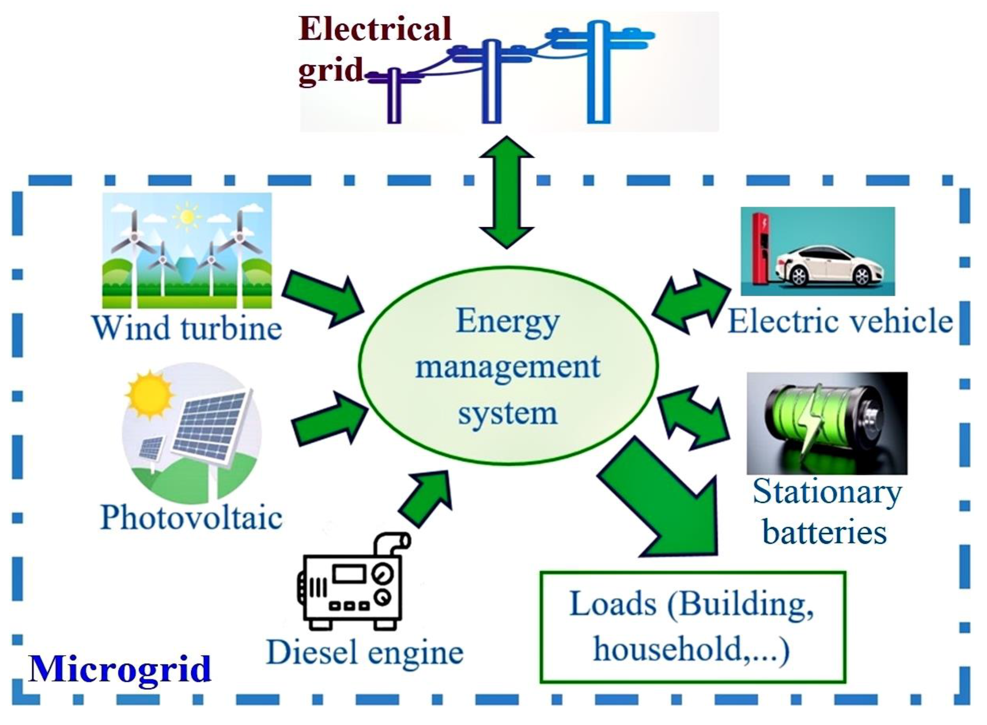
This study specifically focuses on regions with abundant renewable energy resources, particularly coastal areas in the southern region of Vietnam. As a novel contribution, this research introduces a plan to restrict the generation capacity of the national power grid, which has not yet been addressed carefully. Additionally, another innovative aspect lies in the utilization of the Lagrange multiplier theory as the basis for the proposed HEMS. This approach also operates on the principle of prioritization, simplifying the computational process significantly.
The remaining sections of this research paper are structured as follows. In the subsequent section, a system is proposed to optimize energy distribution within the microgrid (MG) by taking into account electric vehicles (EVs) in both grid-connected and isolated modes. Section 3 elaborates on the specific details of the optimization method employed in this study, then Section 4 presents and discusses the simulation results obtained from two test cases. Ultimately, the conclusion of this work is provided in Section 5. All of the mathematical variables and parameters used in this paper are declared in Nomenclature in the appendix.

2. Microgrid Models

A microgrid is an energy system that provides power to a designated area, such as a university campus, business center, hospital, or residential area. These systems are powered by various DERs, including RESs and traditional sources, as well as ESS, often in the form of batteries. Some microgrids also offer charging stations for EVs. Advanced microgrids are often referred to as “smart”, which is due to the microgrid controller that manages the generators, batteries, and local building energy systems in order to meet energy demands. The controller intelligently manages these resources and to maximize economic benefits, these energy systems can also be connected to the national electrical grid, as illustrated in Figure 1.
In this work, the proposed microgrid system can operate in two modes, either as an isolated system or as a system connected to the main grid. When it is operating as an isolated system, the power generated within the microgrid is utilized to meet the energy needs of the local area. Conversely, if the microgrid is interconnected with the primary electrical grid, it possesses the capability to either deliver or acquire power from the grid. The determination of the microgrid’s operational mode is contingent upon various factors, including local energy production, energy demand, and the prevailing energy prices within the main grid. The MG system is equipped with a variety of energy resources and technology, such as renewable energy sources, ESS, and EVs, as shown in Figure 1. The capacity limits of each component in the system are specified in Table 1, and they will be used as constraints in the optimization problem in this study.

3. Optimization Method

The Lagrange multiplier method is a mathematical optimization technique used to find the local maxima and minima of a function while taking into account equality constraints. This method has the benefit of not requiring explicit parameterization of the constraints, making it a useful tool for solving complex optimization problems with constraints. The method can also accommodate inequality constraints through the advanced Lagrange multiplier technique known as the Karush–Kuhn–Tucker conditions. The process involves the following steps:
In order to determine the maximum or minimum value of a function f x that has the constraints g ( x ) = 0 and h ( x ) 0 , the method introduces Lagrange multipliers λ and μ as additional variables, known as Lagrange multipliers, to incorporate the constraints into the objective function.
  • Form the Lagrangian function L :
    L x , λ , μ = f x λ g x μ ( h x )
    where x represents the variables of the objective function, λ and μ represent the Lagrange multipliers, g ( x ) represents the equality constraints, and h ( x ) represents the equality constraints.
  • Solve the following system of equations to obtain ( x , λ , μ )
    L x , λ , μ = 0 μ h x = 0
To find the extrema of the objective function subject to the constraints, the partial derivatives of the Lagrangian function with respect to each variable x and each Lagrange multiplier λ, μ are computed. These partial derivatives are set to zero in order to determine the critical points of the Lagrangian function. Solving the system of equations formed by setting the partial derivatives to zero yields the values of the variables x and Lagrange multipliers λ, μ that correspond to the extrema of the objective function subject to the constraints. The obtained solution can be further evaluated to determine if it is a maximum, minimum, or a saddle point.
  • Calculate the value of the objective function f(x) based on the optimal solution ( x , λ , μ ):
    f m i n = min x * f ( x * ) f m a x = max x * f ( x * )
By following these steps, the Lagrange multipliers method allows us to efficiently find the extrema of a function subject to equality and inequality constraints. It is a powerful technique for solving constrained optimization problems and is widely used in various fields of mathematics, economics, engineering, and physics.

3.1. Mathematical Model of EMS

This section outlines the development of the EMS model for microgrids. In order to effectively implement a 24 h energy management system, certain details must be established beforehand. These details include:
  • Predicted load levels for every hour of the upcoming day
  • Predicted wind and solar energy generation levels for every hour of the upcoming day
  • Characteristics, power limits, and cost functions for each system component
  • Starting charge level of the energy storage system
  • Starting charge level and departure schedule of electric vehicles
  • Electricity pricing information
The energy management system model has the capability to operate in two modes: isolated mode and grid-connected mode. In the isolated mode, the microgrid operates independently and utilizes only the power generated within its boundaries. During the grid-connected mode, the microgrid establishes a connection with the main grid, enabling it to actively engage in both power supply and consumption.
Objective function:
min   F = F g P g t + F d e P d e t + F e s s S O C t + F e v e v S O C t
where
  • F: cost function of the system;
  • Fde(): cost function of the diesel engine;
  • Fess(): cost function of the stationary battery;
  • Fev(): cost function of the EV’s built-in battery;
  • Fg(): cost function of the national grid;
  • Pde(t): power of the diesel engine at point time t;
  • Pg(t): power of the national grid at point time t;
  • SOC(t): state of charge of the stationary battery at point time t;
  • evSOC(t): state of charge of the EV’s built-in battery at point time t.
Cost function of diesel engine [12]
F d e P d e t = a · P d e ( t ) 2 + b · P d e ( t ) + c
where a, b and c are the coefficients of the cost function that are proportional to the diesel price as defined in [12].
The following constraints are applied to the objective function:
1/Power output of DE at point time t
P d e m i n P d e ( t ) P d e m a x
where
  • P d e m i n : minimum power of the diesel engine;
  • P d e m a x : maximum power of the diesel engine.
2/Power balance of the sources and loads
P g t = P l o a d s t P w t t P p v t P e s s t P e v t P d e t
where
  • Pde (t): power of the diesel engine at point time t;
  • Pg (t): power of the national grid at point time t;
  • Pess (t): power of the stationary battery at point time t;
  • Ploads (t): power of the loads at point time t;
  • Pev (t): power of the EV’s built-in battery at point time t;
  • PWt (t): power of the wind turbine at point time t;
  • Ppv (t): power of the photovoltaic array at point time t.
3/ESS power output
P e s s m i n P e s s ( t ) P e s s m a x
where
  • P e s s m i n : minimum power of the stationary battery;
  • P e s s m a x : maximum power of the stationary battery.
4/EVs power output
P e v m i n P e v ( t ) P e v m a x
where
  • P e v m i n : minimum power of the EV’s built-in battery;
  • P e v m a x : maximum power of the EV’s built-in battery.
5/Dynamic performance of ESS and EV [12]
s o c t + 1 = s o c t P e s s ( t ) W e s s
s o c m i n s o c ( t + 1 ) s o c m a x
e v S O C t + 1 = e v S O C t P e v ( t ) W e v
e v S O C m i n e v S O C ( t + 1 ) e v S O C m a x
F e s s S O C t = k 1 · ( 1 k 2 · S O C t + k 3 · S O C t 2 ) · ( 1 + 1 λ )
F e v e v S O C t = E V t · [ k 1 · 1 k 2 · e v S O C t + k 3 · e v S O C t 2 · 1 + 1 λ ]
where
  • S O C m i n : minimum capacity of the stationary battery;
  • S O C m a x : maximum capacity of the stationary battery;
  • e v S O C m i n : minimum capacity of the EV’s built-in battery;
  • e v S O C m a x : maximum capacity of the EV’s built-in battery;
  • EV(t): Operating status of EV (EV(t) = 1: EV is at home; EV(t) = 0: EV is not at home);
  • k1, k2, k3: coefficients related to the rated depth of discharge of the battery [12];
  • λ : weighting factor assigns the significance of the battery life [12].
The lifetime of a battery is influenced by various factors, including temperature, storage conditions, depth of discharge, and discharge rate, among others. In the context of power system optimization, the discharge rate and depth of discharge emerge as the primary factors impacting battery lifespan. Consistently discharging a battery to a significant depth leads to a decrease in its overall lifespan. Consequently, an inverse relationship exists between the charge life of a battery and the depth of discharge. Operating the battery at a high discharge rate continuously results in a reduction of its charge life. Thus, the charge life of the battery and the discharge rate demonstrate an inverse relationship [43]. The values of k1, k2, and k3 were determined by utilizing the best-fit parameters obtained from experimental data in the referenced research [43]. The formulation used in this study was derived from the work presented in [12].
In this research, the EV part in the MG system is considered as a mobility battery storage. For simplicity, the built-in battery of the EV only can discharge the power to the MG system or be charged from the system when it is at home with a charging terminal, i.e., EV(t) = 1. Moreover, the types of the stationary battery in the system and the EV’s built-in battery are assumed to be the same type.
The final cost function of the considered MG system is given by (13), where the details are shown in Appendix A.
min   F = c g t · P g t + a · P d e ( t ) 2 + b · P d e t + c + k 1 · 1 k 2 · s o c t + k 3 · s o c t 2                                         · 1 + 1 λ + E V t · [ k 1 · 1 k 2 · e v s o c t + k 3 · e v S O C t 2 · 1 + 1 λ ]

3.2. Applying Optimize Technique

The final function in the proposed method can be described as a multi-variable quadratic function that can be solved using the Lagrange multiplier theorem. The procedure for the proposed method is described in Algorithm 1. In this process, the inputs for the system, including electricity price, photovoltaic power, wind power, and load demand, are treated as constants in the equation and can be derived from either forecasted data obtained from a data system or real-time data. Subsequently, the optimal solution is obtained by taking the partial derivative with respect to each variable, while taking into account their respective constraints. A flowchart of the procedure is presented in Figure 2. It should be noted that only the values of min3, max3, and min4 (the limitations of the main grid) remain constant throughout the method, while min1, max1, min2, and max2 are variable and depend on the energy consumption over a certain period. For example, the current SOC of the stationary battery is max2 = S O C m a x = 30% as the maximum capacity of the battery used for the optimization procedure at this time, and the charged power in the SOC of the battery for one hour is 15%. Thus, after being charged, the maximum value of the SOC of the battery at the next hour will be around 45%, which means that the max2 utilized for the optimization procedure at the next hour will be 45%.
Note that
  • min1 = e v S O C m i n (minimum capacity of the EV’s built-in battery);
  • max1 = e v S O C m a x (maximum capacity of the EV’s built-in battery);
  • min2 = S O C m i n (minimum capacity of the stationary battery);
  • max2 = S O C m a x (maximum capacity of the stationary battery);
  • min3 = P d e m i n (minimum power of the diesel engine);
  • max3 = P d e m a x (maximum power of the diesel engine).
Algorithm 1. Cost function minimization
1.   Objective   function :   Min   F ( P d e , S O C , e v S O C )
2.  Determine the optimal value:
[ P d e , S O C , e v S O C ] = partial   derivative ( F ( P d e , S O C , e v S O C ))
3.  if   ( e v S O C   <   min 1   or   max 1   <   e v S O C )
4.          e v S O C = e v S O C   at   limit = >   P e v using (9)
5.          Compute   P d e   and   S O C   by   taking   partial   derivative   of   F
6.          if  ( S O C   <   min 2   or   max 2   <   S O C )
7.             S O C = S O C at   limit = >   P e s s using (7)
8.             Compute   P d e by   taking   derivative   of   F
9.         end
10.      if  ( P d e   <   min 3   or   max 3   <   P d e )
11.           P d e = P d e at limit
12.      end
13.       Compute   P g using (4)
14.      if   ( min 4   < = P g )
15.           Set   P g to limit
16.          Reduce the power of stationary battery and EV’s battery, priority reduce the power of EV then the stationary battery
17.    end
18.  end
As depicted in Figure 2, the algorithm proposed in this study operates on the principle of prioritization. First, the primary focus is on optimizing the battery life of EVs to ensure that each vehicle’s battery is utilized efficiently. The batteries on EVs serve as a flexible battery reserve, and when the number of vehicles increases, the system benefits from a larger energy storage capacity. To achieve this, the algorithm prioritizes the optimization of battery performance on EVs, which enables more EVs to be integrated into the energy system. Subsequently, the fixed energy storage system of the algorithm, namely the stationary battery, is optimized. This process prioritizes the use of renewable energy sources stored in the batteries and leverages the benefits of obtaining inexpensive electricity from the national electrical grid. Finally, the algorithm optimizes the diesel engine, which is commonly employed to compensate for power deficits in the system and during peak electricity demand hours.

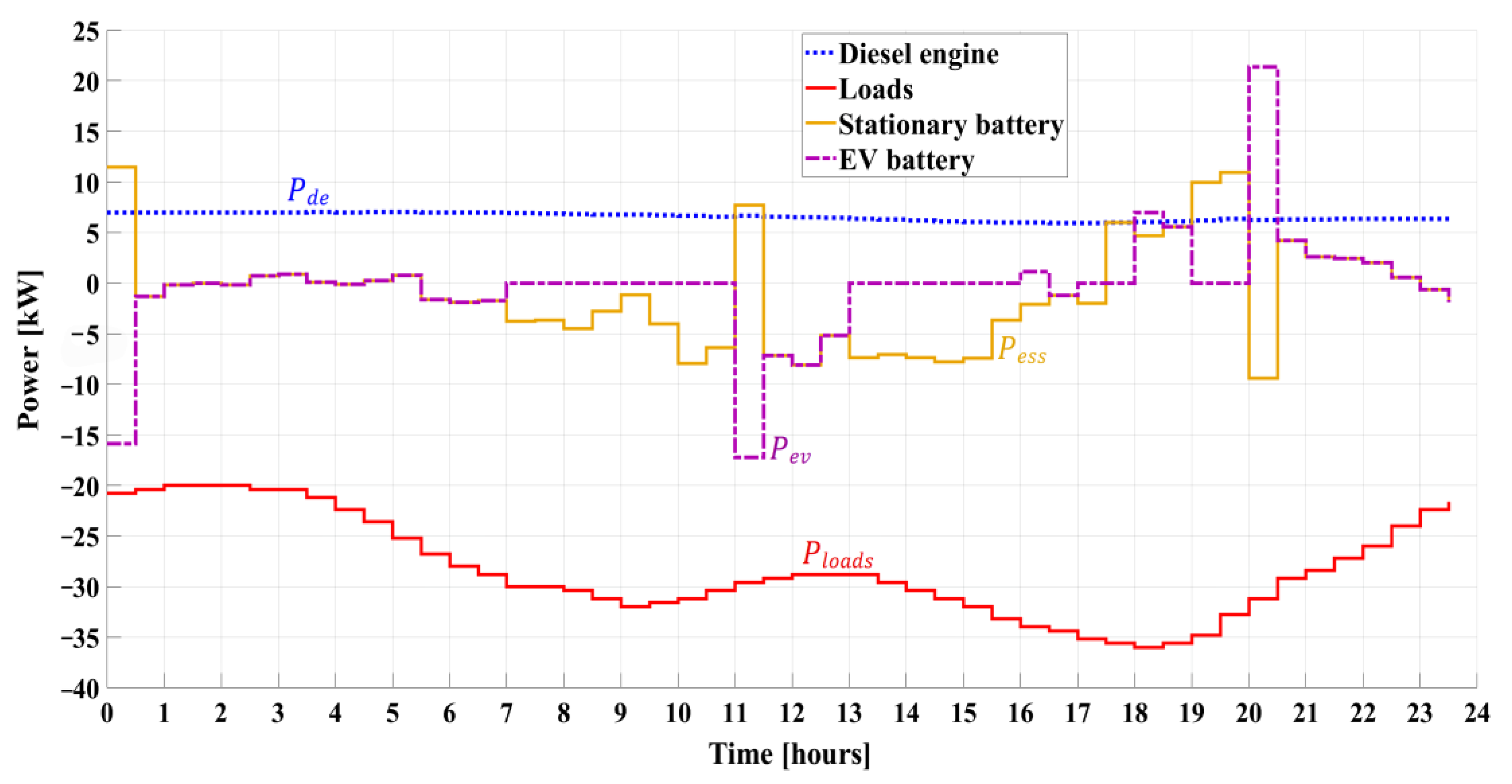
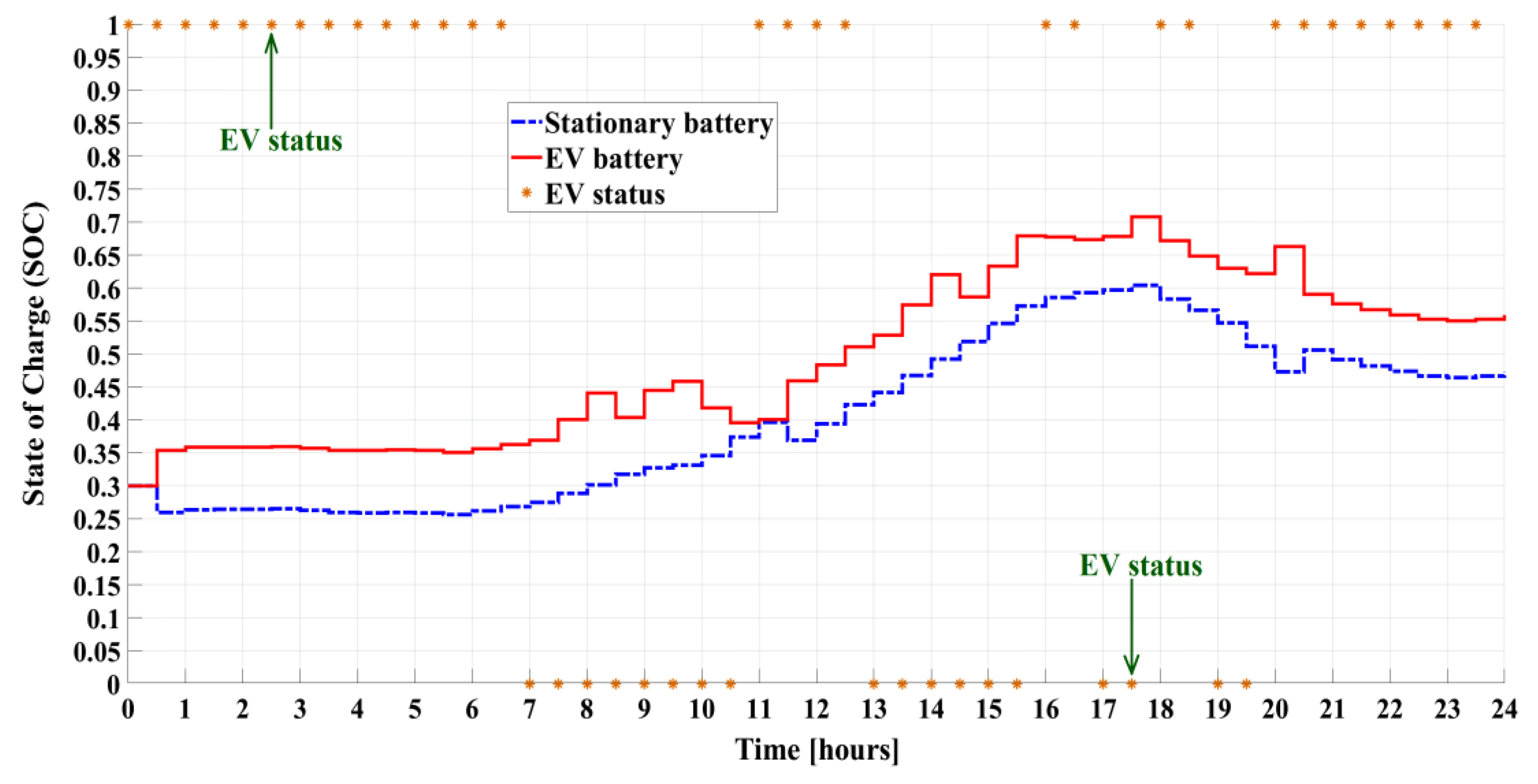
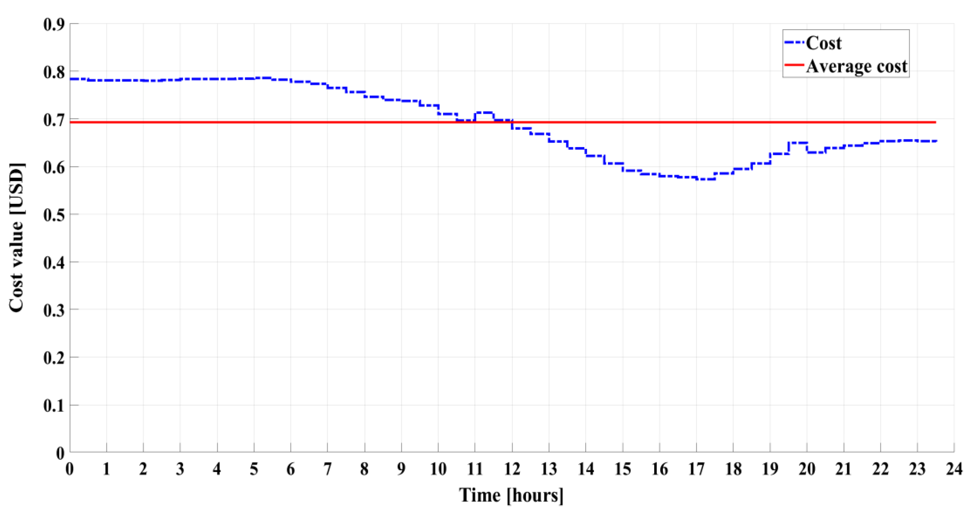
4. Simulation Results

In order to maintain the coherency of the manuscript, the collected data used for the study cases of this paper are described in Section 6.

4.1. Isolated Operation Mode

In Figure 3, an isolated power network operating in an autonomous mode and utilizing RESs and diesel as the primary energy sources is investigated. The chart represents negative power consumption and positive power supply, where negative power represents energy consumption, and positive power represents energy supply to the system. The red line in the chart illustrates the power consumption of loads’ Ploads in a 24 h cycle, with peak hours observed at approximately 9 am and 6 pm; because of the consumption power, Ploads is represented as a negative value. The yellow line represents the capacity of the stationary battery Pess, generating electricity when renewable energy is low and absorbing excess energy created by renewable sources to balance the system’s power. The purple line represents the generating capacity of the EV’s built-in battery Pev, which only operates in the system when the car is present at home. The status of the EV is shown in Figure 4, where the vehicle typically draws electricity from the system to charge when it arrives home at 11 am with a low battery level, and the car’s power is zero when it is not at home. In the evening (8 pm), when the car returns home with a high battery level, it plays a role in supplying energy to the system due to the high demand for electricity from loads. The study also considers a scenario in which the car can be charged outside, resulting in the car returning home with a high battery level. The blue line in the chart represents the power output of the diesel engine Pde, which operates at a low level to ensure immediate power supply to the system in case of energy shortage.
In Figure 4, the status of the EV, as well as the SOC of the stationary battery and EV’s built-in battery, are demonstrated. The operating status of the car is represented by a yellow star, where a value of 1 indicates that the car is at home, and a value of 0 indicates that the car is not at home. The blue dashed–dotted line in the chart represents the SOC of the stationary battery, which is typically charged during the day and supplies power to the system at night. The battery capacity gradually increases until 6 pm and then decreases as the system requires power when renewable energy sources are insufficient. The red solid line illustrates the SOC of the EV, and it is evident that the EV operates as a battery in the system when it is at home. Additionally, the SOC of the EV can increase when the car is not at home due to the random factor of the car being charged outside of the network.
The cost in the isolated mode is presented in Figure 5, and it is calculated based on the cost of operating the diesel engine. The blue line represents the cost incurred at each time slot, while the red line shows the average daily cost. The cost of using the diesel engine ranges from 0.57 to 0.78 USD, with an average of approximately 0.69 USD per 30 min period.

4.2. Grid-Connected Operation Mode

In this test case, Figure 6 illustrates the scheduling in grid-connected mode, where positive power indicates power supply and negative power indicates energy consumption. The power consumption of loads’ Ploads throughout a 24 h cycle is depicted by the yellow solid line in the figure; due to the consumption power, Ploads is shown as a negative value. The red line represents the power obtained from the utility grid Pg, which is positive during the 8 pm–4 am period, indicating that the system is purchasing electricity from the national grid. This occurs because renewable energy is scarce during this period, and the system requires an additional energy source. Additionally, the grid electricity price is low during this time, making it advantageous for the system to store energy in the battery. During most of the time from 4 am to 8 pm, the MG system exports energy to the national grid. However, to prevent overloading the national grid, this study suggests a limit on the power output to the grid, represented by the cyan dashed–dotted line. The power supplied to the grid should not exceed this limit. The purple dotted line displays the power from the stationary battery Pess, which is different from the isolated mode. During the grid-connected mode, the stationary battery is charged during periods of low electricity prices, typically occurring during off-peak hours. Subsequently, the battery generates electricity during peak hours when electricity prices are high, aiming to maximize economic benefits. Similarly, the green line represents the power of the EV Pev, which generates electricity during peak hours when the EV’s battery is fully charged and recharges during off-peak hours when electricity prices are at a lower rate. Lastly, the blue solid line shows the power output of the diesel engine Pde, which operates at a low level to ensure immediate power supply to the system in case of insufficient energy supply.
Furthermore, the SOC of the stationary battery, SOC of the EV’s built-in battery, and EV status are depicted in Figure 7. The operating status of the EV is represented by a yellow star, with a value of 1 indicating that the car is stationary at home and a value of 0 indicating that it is located outside. The blue dashed–dotted line represents the SOC of the stationary battery, which gradually increases from 8 pm to 4 am, indicating the charging period as presented in Figure 6. The battery supplies energy to the system during most of the time from 4 am to 8 pm. The inactive periods of the battery (i.e., 5:30 am–9:30 am and 1 pm–5 pm) are when the operational costs exceed the benefits of selling electricity. During peak electricity price periods (i.e., 10 am–11:30 am and 5:30 pm–8 pm), the battery supplies power to sell to the national grid as the profit from selling electricity outweighs the operational costs. The EV behaves similarly to the stationary battery, but it is essential to maintain the SOC of the EV’s battery at a higher level for transportation purposes, resulting in the red solid line not decreasing to a low value like the blue dashed–dotted line.
The cost in the grid-connected operation mode is displayed in Figure 8. It is calculated from the cost of the diesel engine and the national grid. The blue line represents the cost incurred in operating the diesel system at each time slot, while the red line indicates the daily average cost. The cost of using the diesel engine ranges from −9 to 14 USD, with an average value of around 0.45 USD per 30 min. Despite the significant average cost fluctuations, the electricity cost in this mode is lower compared to that in the isolated mode shown in Figure 5 due to the utilization of electricity trading with the national grid.
In this paper, all the test cases are well performed with a laptop computer equipped with an IntelI CITM) i5-4210U processor running at 1.7 GHz, 12 GB random-access memory (RAM), and integrated Intel(R) HD graphics, and the processing time of the proposed optimization algorithm is within two minutes. It is shown that by using the Lagrange multiplier theory for the optimization algorithm used in the designed HEMS, the computational burden can be reduced substantially.
In future work, the HEMS and optimization algorithm considered in this paper will be appropriately combined with the modified interval fuzzy model in [44] and fuzzy-based control method in [45] in order to further improve the performance and effectiveness.

5. Conclusions

The obtained simulation results have shown that the proposed HEMS and optimization algorithm based on Lagrange multiplier theory in this paper operates effectively under the established constraints in both the standalone and grid-connected scenarios. The power generation and consumption are well balanced, and each component of the designed energy system operates properly within its limits. When comparing the two operational scenarios, it becomes clear that there are several drawbacks to having the MG not connected to the national power grid. For instance, the diesel generator must continuously operate in order to compensate for the shortfall when the renewable energy source is affected by significant changes in the weather. In addition, being isolated from the national electricity system means that all of the electricity generated from renewable sources must be utilized, preventing the system from selling excess electricity and having a load system with a reasonable capacity. Furthermore, when the load capacity in the MG system increases substantially, the system may face a power shortage if extra generators are not installed.
On the other hand, when the MG is connected to the national power grid, the energy system can be designed with a larger capacity for renewable power than its load capacity. The excess energy can then be sold back to the national grid, and diesel engines only operate during times of high electricity prices for the purpose of selling electricity at the most favorable price. Additionally, the amount of electricity transferred to the national power grid can be appropriately limited during times of excess energy, which can be stored in stationary batteries and built-in batteries of EVs for later use or sale with consideration of safe SOC ranges of the batteries. This approach optimizes the total power from renewable energy sources to benefit the other components in the designed system, thus the results are not greatly influenced by whether the solar or wind energy is dominant.

6. Data Collection for Study Cases

The actual price chart of electricity in Vietnam in US dollars (USD), which has been analyzed in [46], is shown in Figure 9. In Vietnam, the cost of industrial electricity fluctuates based on the daily demand, with prices generally higher during peak hours and lower during off-peak hours. Specifically, the highest electricity price is normally observed from 9:30 am to 11:30 am and from 5:00 pm to 8:00 pm. Conversely, the lowest prices are recorded from 10:00 pm to 4:00 am.
The power profiles of wind and solar energy over the course of a single day are shown in Figure 10. Wind energy is depicted as being accessible throughout the entire day, whereas solar energy is limited to daylight hours when sunlight is available.

Author Contributions

Conceptualization and methodology, H.G.T. and N.G.M.T.; software and investigation, H.G.T., L.T.-T. and N.G.M.T.; data curation, H.G.T. and L.T.-T.; result analysis and evaluation, L.T.-T. and N.G.M.T.; writing—review and editing, H.G.T., L.T.-T. and N.G.M.T. All authors have read and agreed to the published version of the manuscript.

Funding

This research received no external funding.

Data Availability Statement

The data is available upon request from the corresponding author.

Conflicts of Interest

The authors declare no conflict of interest.

Nomenclature

a, b, cCoefficients in cost function of diesel engine that are proportional to diesel price
evSOCState of charge of EV’s built-in battery
e v S O C m i n Minimum capacity of EV’s built-in battery
e v S O C m a x Maximum capacity of EV’s built-in battery
EV(t)Operating status of EV
FCost function of designed microgrid system
FdeCost function of diesel engine
FessCost function of stationary battery
FevCost function of EV’s built-in battery
FgCost function of national power grid
k1, k2, k3Coefficients in cost function of battery that are related to rated depth of discharge of battery
λ Weighting factor in cost function of battery that assigns significance of battery life
PdePower of diesel engine
P d e m i n Minimum power of diesel engine
P d e m a x Maximum power of diesel engine
PevPower of EV’s built-in battery
P e v m i n Minimum power of EV’s built-in battery
P e v m a x Maximum power of EV’s built-in battery
PessPower of stationary battery
P e s s m i n Minimum power of stationary battery
P e s s m a x Maximum power of stationary battery
PgPower of national power grid
PloadsPower of loads
PpvPower of photovoltaic array
PWtPower of wind turbine
SOCState of charge of stationary battery
S O C m i n Minimum capacity of stationary battery
S O C m a x Maximum capacity of stationary battery

Appendix A

Prove Formula (13)
The cost function of the national electrical grid is determined as follows:
F g P g t = c g t · P g t
To derive the final cost function in (13), we combine the functions in (2), (11), (12), and (A1).

References

  1. Lasseter, R.H.; Paigi, P. Microgrid: A conceptual solution. In Proceedings of the IEEE 35th Annual Power Electronics Specialists Conference, Aachen, Germany, 20–25 June 2004; pp. 4285–4290. [Google Scholar]
  2. Bevrani, H.; Ghosh, A.; Ledwich, G. Renewable energy sources and frequency regulation: Survey and new perspectives. IET Renew. Power Gener. 2010, 4, 438–457. [Google Scholar] [CrossRef]
  3. Iqbal, S.; Xin, A.; Jan, M.U.; Salman, S.; Zaki, A.U.M.; Rehman, H.U.; Shinwari, M.F.; Abdelbaky, M.A. V2G Strategy for Primary Frequency Control of an Industrial Microgrid Considering the Charging Station Operator. Electronics 2020, 9, 549. [Google Scholar] [CrossRef]
  4. Leon, J.I.; Vazquez, S.; Franquelo, L.G. Multilevel Converters: Control and Modulation Techniques for Their Operation and Industrial Applications. Proc. IEEE 2017, 105, 2066–2081. [Google Scholar] [CrossRef]
  5. de Souza Ribeiro, L.A.; Saavedra, O.R.; de Lima, S.L.; de Matos, J.G. Isolated micro-grids with renewable hybrid generation: The case of Lençóis island. IEEE Trans. Sustain. Energy 2011, 2, 1–11. [Google Scholar] [CrossRef]
  6. Pannala, S.; Padhy, N.P.; Agarwal, P. Effective power management scheme for PV-Battery-DG integrated standalone DC microgrid. IET Electr. Power Appl. 2020, 14, 2322–2330. [Google Scholar] [CrossRef]
  7. Bevrani, H.; Feizi, M.R.; Ataee, S. Robust frequency control in an islanded microgrid: H1 and µ-Synthesis approaches. IEEE Trans. Smart Grid 2015, 7, 706–717. [Google Scholar] [CrossRef]
  8. Frasetyo, M.B.; Wijaya, F.D.; Ali, H.R. Islanded wind farm microgrid stability control using synchronverter algorithm. IEEJ J. Ind. Appl. 2023, 12, 603–612. [Google Scholar] [CrossRef]
  9. Vazquez, S.; Lukic, S.; Galvan, E.; Franquelo, L.G.; Carrasco, J.M.; Leon, J.I. Recent advances on energy storage systems. In Proceedings of the 37th Annual Conference of the IEEE Industrial Electronics Society, Melbourne, Australia, 7–10 November 2011; pp. 4636–4640. [Google Scholar]
  10. Xu, D.; Liu, J.; Yan, X.-G.; Yan, W. A novel adaptive neural network constrained control for a multi-area interconnected power system with hybrid energy storage. IEEE Trans. Ind. Electron. 2018, 65, 6625–6634. [Google Scholar] [CrossRef]
  11. Kempton, W.; Letendre, S.E. Electric vehicles as a new power source for electric utilities. Transp. Res. D Transp. Environ. 1997, 2, 157–175. [Google Scholar] [CrossRef]
  12. Zhao, Z. Optimal Energy Management for Microgrids. Ph.D. Thesis, Clemson University, Greenville, SC, USA, 2012. [Google Scholar]
  13. Thao, N.G.M.; Uchida, K.; Kofuji, K.; Jintsugawa, T.; Nakazawa, C. An automatic-tuning scheme based on fuzzy logic for active power filter in wind farms. IEEE Trans. Control Syst. Technol. 2019, 27, 1694–1702. [Google Scholar] [CrossRef]
  14. Wang, S.; Ge, L.; Wang, K.; Cai, S.; Mihet-Popa, L. Energy management and economic operation optimization of microgrid under uncertainty. In Energy Management of Distributed Generation Systems; IntechOpen: London, UK, 2016; p. 249. [Google Scholar]
  15. Elsied, M.; Oukaour, A.; Gualous, H.; Hassan, R. Energy management and optimization in microgrid system based on green energy. Energy 2015, 84, 139–151. [Google Scholar] [CrossRef]
  16. Tian, P.; Xiao, X.; Wang, K.; Ding, R. A hierarchical energy management system based on hierarchical optimization for microgrid community economic operation. IEEE Trans. Smart Grid 2016, 7, 2230–2241. [Google Scholar] [CrossRef]
  17. Indragandhi, V.; Logesh, R.; Subramaniyaswamy, V.; Vijayakumar, V.; Siarry, P.; Uden, L. Multi-objective optimization and energy management in renewable based AC/DC microgrid. Comput. Electr. Eng. 2018, 70, 179–198. [Google Scholar]
  18. Marzband, M.; Yousefnejad, E.; Sumper, A.; Domínguez-García, J.L. Real time experimental implementation of optimum energy management system in standalone microgrid by using multi-layer ant colony optimization. Int. J. Electr. Power Energy Syst. 2016, 75, 265–274. [Google Scholar] [CrossRef]
  19. Dulău, L.I.; Bică, D. Optimization of generation cost in a microgrid. Procedia Manuf. 2018, 22, 703–708. [Google Scholar] [CrossRef]
  20. Porsinger, T.; Janik, P.; Leonowicz, Z.; Gono, R. Modelling and Optimization in Microgrids. Energies 2017, 10, 523. [Google Scholar] [CrossRef]
  21. Zhang, W.; Maleki, A.; Rosen, M.A.; Liu, J. Optimization with a simulated annealing algorithm of a hybrid system for renewable energy including battery and hydrogen storage. Energy 2018, 163, 191–207. [Google Scholar] [CrossRef]
  22. Yamaguchi, T.; Matsumoto, T. Autonomous control for cooperative operation between energy storage systems. IEEJ J. Ind. Appl. 2023, 12, 643–652. [Google Scholar] [CrossRef]
  23. Eydi, M.; Alishahi, M.; Zarif, M. A novel output power determination and power distribution of hybrid energy storage system for wind turbine power smoothing. IET Electr. Power Appl. 2022, 16, 1559–1575. [Google Scholar] [CrossRef]
  24. Mansouri, S.; Zishan, F.; Montoya, O.D.; Azimizadeh, M.; Giral-Ramírez, D.A. Using an intelligent method for microgrid generation and operation planning while considering load uncertainty. Results Eng. 2023, 17, 100978. [Google Scholar] [CrossRef]
  25. Shirole, A.; Wagh, M.; Kulkarni, V.; Patil, P. Short-term energy scenario of district energy system using optimised renewable energy mix with and without energy storage. Results Eng. 2023, 18, 101017. [Google Scholar] [CrossRef]
  26. Twaisan, K.; Barışçı, N. Integrated Distributed Energy Resources (DER) and Microgrids: Modeling and Optimization of DERs. Electronics 2022, 11, 2816. [Google Scholar] [CrossRef]
  27. Dong, H.; Fang, Z.; Ibrahim, A.-W.; Cai, J. Optimized Operation of Integrated Energy Microgrid with Energy Storage Based on Short-Term Load Forecasting. Electronics 2021, 11, 22. [Google Scholar] [CrossRef]
  28. Lv, J.; Wang, X.; Wang, G.; Song, Y. Research on Control Strategy of Isolated DC Microgrid Based on SOC of Energy Storage System. Electronics 2021, 10, 834. [Google Scholar] [CrossRef]
  29. Olivares, D.E.; Canizares, C.A.; Kazerani, M. A centralized optimal energy management system for microgrids. In Proceedings of the 2011 IEEE Power and Energy Society General Meeting, Detroit, MI, USA, 24–28 July 2011; pp. 1–6. [Google Scholar]
  30. Hazem Mohammed, O.; Amirat, Y.; Benbouzid, M. Economical Evaluation and Optimal Energy Management of a Stand-Alone Hybrid Energy System Handling in Genetic Algorithm Strategies. Electronics 2018, 7, 233. [Google Scholar] [CrossRef]
  31. Baziar, A.; Kavousi-Fard, A. Considering uncertainty in the optimal energy management of renewable micro-grids including storage devices. Renew. Energy 2013, 59, 158–166. [Google Scholar] [CrossRef]
  32. Hosseinzadeh, M.; Salmasi, F.R. Robust Optimal Power Management System for a Hybrid AC/DC Micro-Grid. IEEE Trans. Sustain. Energy 2015, 6, 675–687. [Google Scholar] [CrossRef]
  33. Thirunavukkarasu, G.S.; Seyedmahmoudian, M.; Jamei, E.; Horan, B.; Mekhilef, S.; Stojcevski, A. Role of optimization techniques in microgrid energy management systems—A review. Energy Strategy Rev. 2022, 43, 100899. [Google Scholar] [CrossRef]
  34. Shezan, S.A.; Kamwa, I.; Ishraque, F.; Muyeen, S.M.; Hasan, K.N.; Saidur, R.; Rizvi, S.M.; Shafiullah; Al-Sulaiman, F.A. Evaluation of Different Optimization Techniques and Control Strategies of Hybrid Microgrid: A Review. Energies 2023, 16, 1792. [Google Scholar] [CrossRef]
  35. Lipu, M.H.; Ansari, S.; Miah, S.; Hasan, K.; Meraj, S.T.; Faisal, M.; Jamal, T.; Ali, S.H.; Hussain, A.; Muttaqi, K.M.; et al. A review of controllers and optimizations based scheduling operation for battery energy storage system towards decarbonization in microgrid: Challenges and future directions. J. Clean. Prod. 2022, 360, 132188. [Google Scholar] [CrossRef]
  36. Shafiullah, M.; Refat, A.M.; Haque, M.E.; Chowdhury, D.M.H.; Hossain, M.S.; Alharbi, A.G.; Alam, M.S.; Ali, A.; Hossain, S. Review of recent developments in microgrid energy management strategies. Sustainability 2022, 14, 14794. [Google Scholar] [CrossRef]
  37. Tostado-Véliz, M.; Kamel, S.; Hasanien, H.M.; Turky, R.A.; Jurado, F. Uncertainty-aware day-ahead scheduling of microgrids considering response fatigue: An IGDT approach. Appl. Energy 2022, 310, 118611. [Google Scholar] [CrossRef]
  38. Kamal, F.; Chowdhury, B. Model predictive control and optimization of networked microgrids. Int. J. Electr. Power Energy Syst. 2022, 138, 107804. [Google Scholar] [CrossRef]
  39. Alvarez, J.A.M.; Zurbriggen, I.G.; Paz, F.; Ordonez, M. Microgrids Multiobjective Design Optimization for Critical Loads. IEEE Trans. Smart Grid 2022, 14, 17–28. [Google Scholar] [CrossRef]
  40. Cavus, M.; Allahham, A.; Adhikari, K.; Zangiabadi, M.; Giaouris, D. Energy Management of Grid-Connected Microgrids Using an Optimal Systems Approach. IEEE Access 2023, 11, 9907–9919. [Google Scholar] [CrossRef]
  41. Ali, M.; Abdulgalil, M.A.; Habiballah, I.; Khalid, M. Optimal Scheduling of Isolated Microgrids with Hybrid Renewables and Energy Storage Systems Considering Demand Response. IEEE Access 2023, 11, 80266–80273. [Google Scholar] [CrossRef]
  42. Tran, H.G.; Thao, N.G.M. Ton-That. Energy management and optimization method based on Lagrange multiplier for microgrid with considerations of electricity price and vehicle. In Proceedings of the 2021 IEEE 10th Global Conference on Consumer Electronics, Kyoto, Japan, 12–15 October 2021; pp. 951–952. [Google Scholar]
  43. Drouilhet, S.; Johnson, B.; Drouilhet, S.; Johnson, B. A battery life prediction method for hybrid power applications. In Proceedings of the 35th Aerospace Sciences Meeting and Exhibit, Reno, NV, USA, 6–9 January 1997; p. 948. [Google Scholar]
  44. Thao, N.G.M.; Uchida, K. An improved interval fuzzy modeling: Applications to estimate photovoltaic/wind/battery power in renewable energy systems. Energies 2018, 11, 482. [Google Scholar] [CrossRef]
  45. Mukhatov, A.; Thao, N.G.M.; Do, T.D. Linear quadratic regulator and fuzzy control for grid-connected photovoltaic systems. Energies 2022, 15, 1286. [Google Scholar] [CrossRef]
  46. Retail Electricity Price in Vietnam. Available online: https://www.evn.com.vn/c3/evn-va-khach-hang/Bieu-gia-ban-le-dien-9-79.aspx (accessed on 29 October 2023).
Figure 1. Proposed MG system.
Electronics 12 04513 g001
Figure 2. A flow chart of the method employed in this investigation.
Electronics 12 04513 g002
Figure 3. Energy scheduling in isolated mode.
Electronics 12 04513 g003
Figure 4. SOC of stationary battery and EV with EV’s status in isolated mode.
Electronics 12 04513 g004
Figure 5. Cost value in isolated mode.
Electronics 12 04513 g005
Figure 6. Energy scheduling in grid-connected mode.
Electronics 12 04513 g006
Figure 7. SOC of the stationary battery and EV with EV’s status in grid-connected mode.
Electronics 12 04513 g007
Figure 8. Cost value in grid-connected mode.
Electronics 12 04513 g008
Figure 9. Electricity price considered in this study.
Electronics 12 04513 g009
Figure 10. Wind and solar PV power profiles.
Electronics 12 04513 g010
Table 1. Power limits of components in considered MG.
Unit TypeMin Power [kW]Max Power [kW]
Diesel engine (DE)530
Wind turbine (WT)050
Photovoltaic (PV) array030
Stationary battery used as an energy storage system (ESS)−3030
Buil-in battery of electric vehicle (EV)−3838
Disclaimer/Publisher’s Note: The statements, opinions and data contained in all publications are solely those of the individual author(s) and contributor(s) and not of MDPI and/or the editor(s). MDPI and/or the editor(s) disclaim responsibility for any injury to people or property resulting from any ideas, methods, instructions or products referred to in the content.

