Article

A Novel Energy Management Control Scheme for a Standalone PV System in a DC Nanogrid

1
Department of Engineering and Architecture, University of Parma, 43124 Parma, Italy
2
CIDEA—Centro Interdipartimentale per l’Energia e l’Ambiente, University of Parma, 43124 Parma, Italy
*
Author to whom correspondence should be addressed.
Electronics 2023, 12(23), 4725; https://doi.org/10.3390/electronics12234725
Submission received: 27 October 2023 / Revised: 13 November 2023 / Accepted: 14 November 2023 / Published: 21 November 2023
(This article belongs to the Special Issue Energy Harvesting and Storage Technologies)

Abstract

:
Distributed energy resources (DERs), such as photovoltaic (PV) sources, together with storage systems, such as battery energy storage systems (BESS), are increasingly present and necessary in our electricity distribution networks. Furthermore, the need for efficient use of energy from DERs, especially in developing countries and remote communities, must be addressed with the development of nanogrids (NGs), particularly DC NGs, and standalone PV systems with adequate control strategies. This paper investigates the control and dynamic operation of a standalone PV system. It consists mainly of three DC–DC power converters for the PV source interface, battery management, and load voltage control. A two-level modulation scheme is applied to each of these converters to switch them ON and OFF. A maximum power point tracking (MPPT) closed-loop voltage control system is implemented to make sure that the PV operates at optimum power regardless of the irradiance level or temperature, while battery voltage and load-side voltage control are also implemented to indirectly provide the required load power. The control of each of the converters is achieved by deriving their small-signal models using a state-space approach from which various control objectives are implemented. The DC-link is clamped by a BESS which acts as a backup source to provide power to the DC load in the absence of sufficient power from the PV panel. The dynamic operation of the whole system is enhanced by proposing a robust feedforward scheme that improves the response of the system in the presence of disturbances. The models are analyzed and implemented using PLECS, and numerical simulations are performed to validate the developed models and control schemes.

1. Introduction

Due to the increasing environmental issues of global warming and pollution caused by the use of fossil fuels, renewable energy sources (RES) have been seen as a solution to mitigate this environmental crisis [1]. Amongst the vast array of RES available, the photovoltaic (PV) system is the most used one globally due to its long life, low maintenance cost, high reliability, and presence of solar energy in every part of the world [2]. PV systems convert solar energy directly into DC electrical power using its semiconductor properties [3]. They can be operated in standalone (off-grid) mode, grid-connected mode, or hybrid mode [2,4]. They are used in standalone mode to provide energy in rural and remote areas that cannot be reached by the grid or where high investment costs prevent connection to the grid (islanded operation) [5]. When a grid connection is available, PV systems are used mostly as distributed generation (DG) power sources. Moreover, if the PV systems include a BESS, they can be used to reduce the stress on the grid resulting from increasing and unpredictable load power demand [6].
Despite the various positives that come with the use of PV systems, one of its main drawbacks is its intermittent nature [7]. The output power of PV systems depends largely on environmental irradiance and ambient temperature and given that these parameters vary continuously throughout a 24 h day cycle, the output power of the PV module continuously fluctuates [8,9]. To tackle this issue, and the increased presence of DERs, in particular for off-grid applications, the development and deployment of small-scale grids is necessary. In particular, for residential or commercial building electrical systems, NGs involving PV modules should include two key elements: a maximum power point tracking (MPPT) controller to make sure that at any point in the operation of the PV system, optimum power can be extracted from it at some specified voltage and current [4] and a storage system [10]. The storage system enables storing the surplus energy produced by the PV system when the solar radiation level is quite high. The stored energy is then released to the load when the PV is in shutdown mode or when it produces less energy than needed [11].
Amongst all the energy storage devices available, the battery is the most used one due to its high energy density and high performance. The battery can be sized considering different elements: the power quantity demand and the habits of use at NG level, the PV module power installed, the mean weather conditions in terms of irradiance and temperature, and, finally, the desired autarky. In any case, an efficient battery management system (BMS) is needed to make sure that the charging and discharging of the battery take place within its manufactured limits in order to protect the battery and increase its life [12]. The BMS continuously monitors the state of health (SoH), state of charge (SoC), the charge and discharge currents, and the voltage of the battery [13,14]. In the literature, several topologies exist for connecting the battery to the DC-bus. The DC-link can serve and receive current through the battery either through a bidirectional DC–DC converter [4,15,16,17] (Figure 1), which permits the effective implementation of the BMS, or through a direct coupling at the load side or the PV side [6,18,19,20] (Figure 2). A direct battery coupling architecture enables the reduction in the size of the system and possibly increases system efficiency even though it makes it very difficult to control the charge and discharge currents of the battery. Hybrid energy storage schemes consisting of battery and ultracapacitors have been implemented by [21,22] to provide for quicker charge and discharge rates, higher power densities, which is not possible only with batteries, and higher system stability. Generally, step-down converters are used when the PV voltage is higher than the battery voltage, while step-up converters are used when the PV output voltage is lower than the battery voltage.
With regard to the MPPT controller, many different algorithms exist in the literature that are used to fulfill this purpose as reviewed in [23]. Amongst all the techniques, the most used ones are perturb and observe (P&O) and incremental conductance (INC). The MPPT controller can directly produce the DC–DC converter duty cycle needed to extract maximum power as implemented in [24,25] or it can produce a reference voltage/current which is passed through a voltage/current control loop as in [26,27,28]. The former approach increases the switching stress and losses in the converter. The latter approach is the preferred option as it avoids overshoots and oscillations, which enhances the transient and steady-state responses of the converter [29].
The rest of this paper is organized as follows: in Section 2, we describe the topology of the standalone energy management system and the models of the various components such as the PV module and the battery. In Section 3, a complete description of the power management system is given with explanations of the expected power flows under different operating conditions of the PV module and BESS. Section 4 presents the small-signal analysis of the complete system using the state space approach, which is fundamental in deriving the control objectives set forth after that. In Section 5, some simulations are performed using PLECS, and the results are described. Finally, we conclude the work and give possible improvements to it in Section 6.

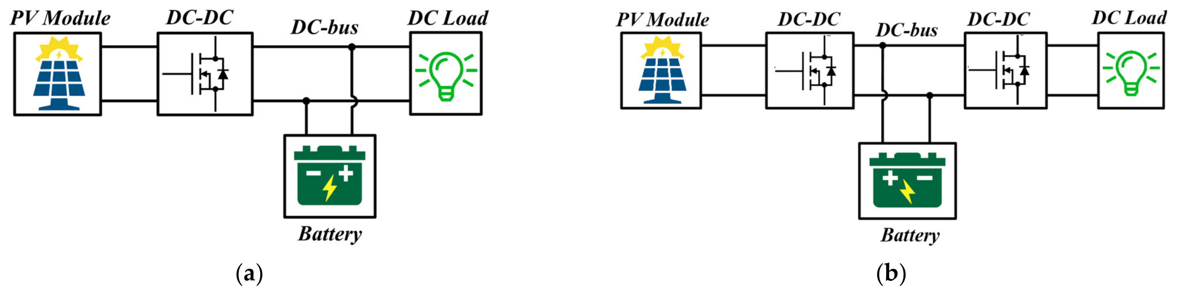
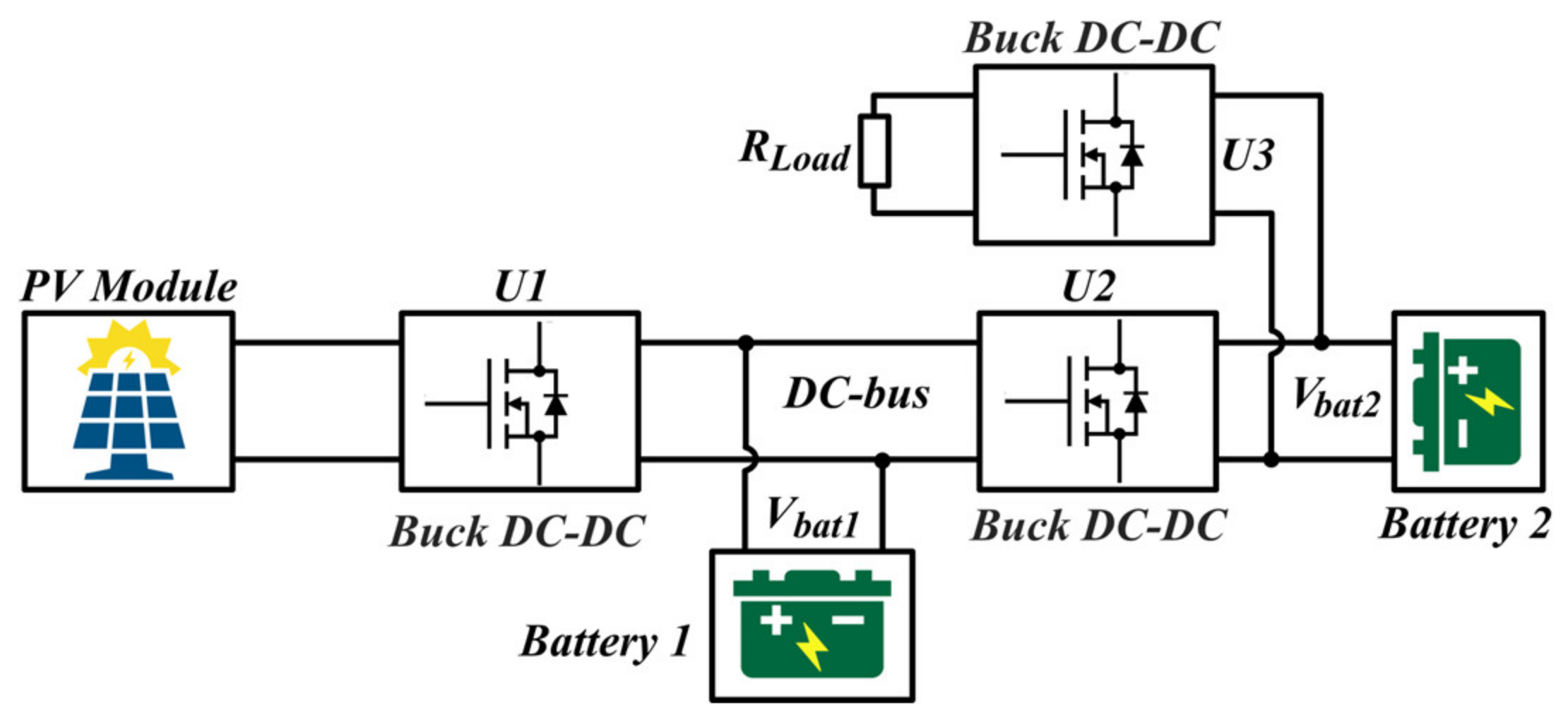
2. System Configuration and Component Modeling
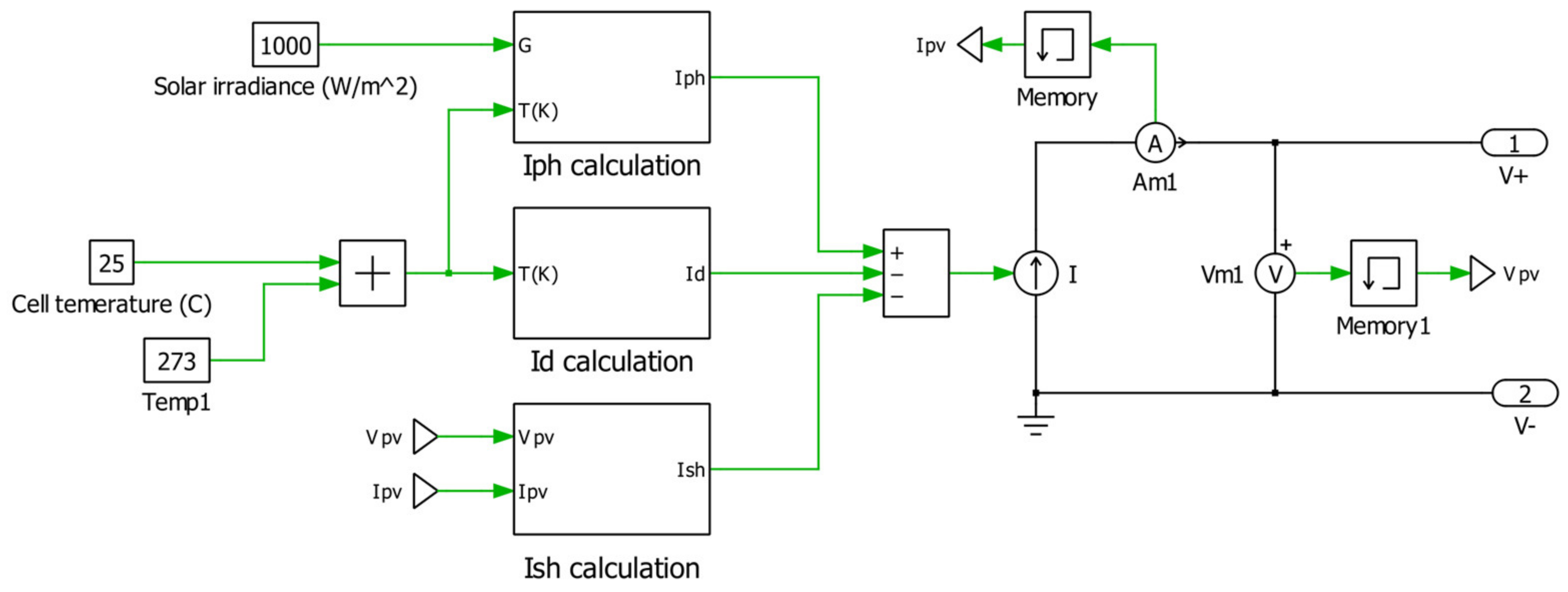
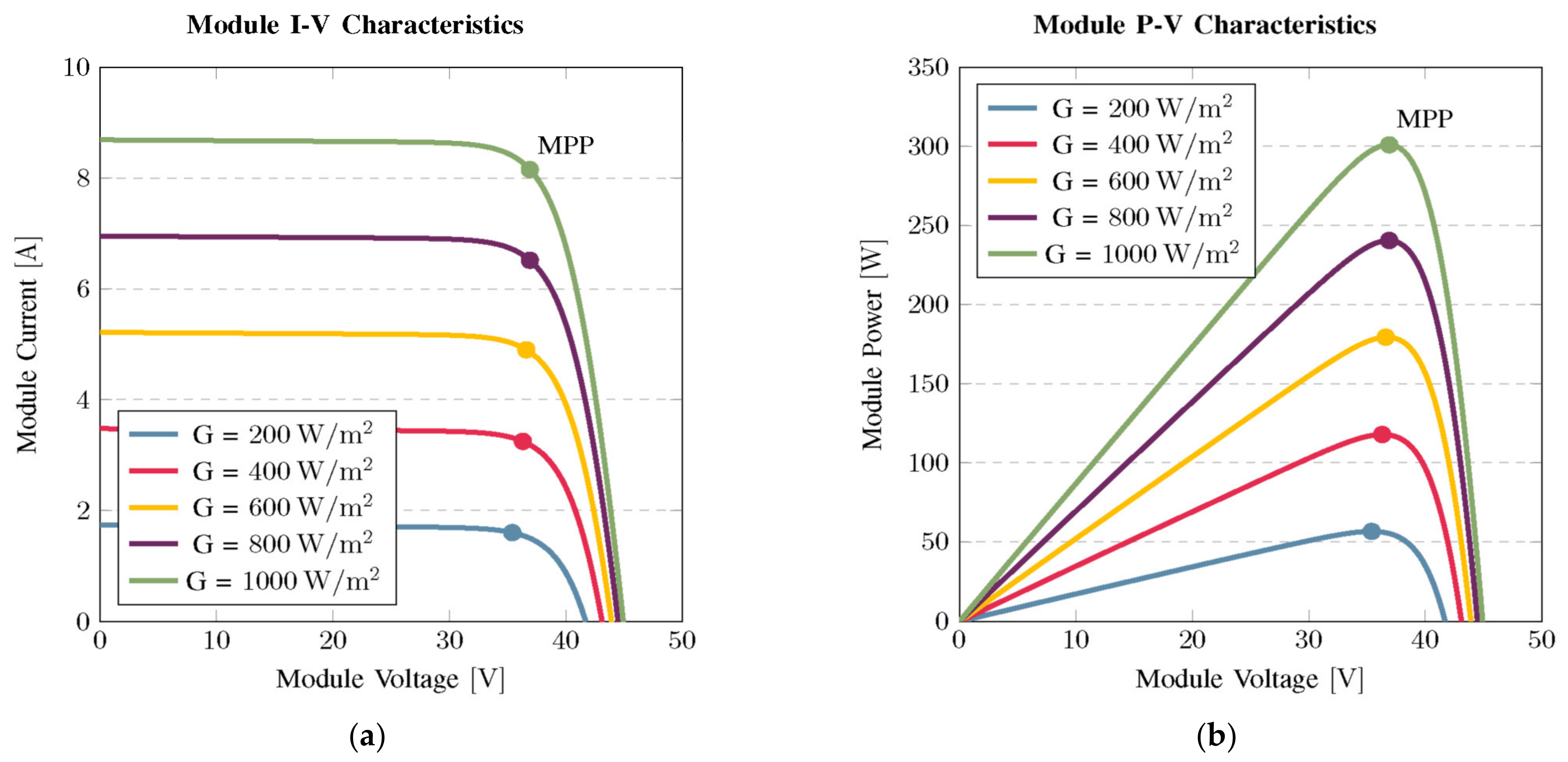
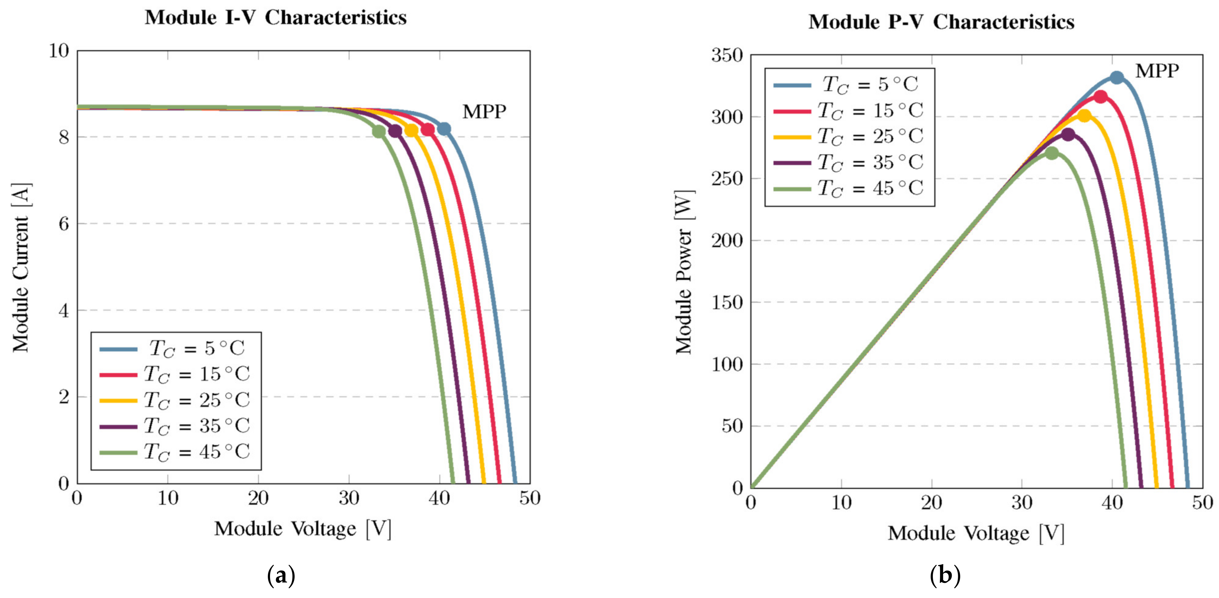
The standalone PV system under study is shown in Figure 3. It consists of a PV module, a buck converter (U1) to step down the PV voltage to a value acceptable by the BESS (battery 1), another buck converter (U2) which is used to charge battery 2, and the last DC–DC buck converter (U3), which provides regulated output voltage to the resistive load.
The two batteries have been chosen with two different nominal voltage values, a higher voltage for battery 1 to obtain higher efficiencies for the PV power extraction, and a lower voltage for battery 2 to reduce the voltage step-down ratio for the load interfacing. In terms of capacity, a strategy to improve the efficiency could be the one of defining the capacity in relation to the battery voltage: the higher the voltage, the higher the capacity. In this way, it is possible to reduce the power losses due to the copper connections by having similar current rates on the two batteries. Finally, from the economical point of view, a double voltage conversion and a distribution in terms of spatial arrangement of the batteries, whereby battery 2 is placed near to the load, could reduce initial investment costs for the overall installation, in relation to the application. In fact, having the possibility to install a high-sized capacity near the PV models could be such expensive as installing two batteries with smaller power electronic converters in strategic locations.
To perform simulations with the various components, electrical models are needed in either PLECS v4.6.4 or MATLAB/Simulink 2020b sourced from Parma, Italy. Therefore, we shall proceed with deriving the electrical models of the most important components of the system, namely the PV module and the BESS.

2.1. Solar PV Array

PV modules generally consist of various combinations of series and parallel cells that produce the required voltage and current at a given irradiance and temperature level [30]. Two main electrical circuit models are used that describe the behavior of PV modules: the single-diode model and the double-diode model [31,32]. These are shown in Figure 4. For this work, the single-diode model will be used to perform the simulations due to its simplicity and computational efficiency.
The mathematical relationships modeling the behavior of the PV equivalent circuit are usually non-linear as presented below. As seen from Figure 4a, the output current of the PV module (IL) is given by:
I L = I p h I D I s h
where Iph is the photo-generated current, ID is the current through the diode, and Ish is the current through the shunt resistor. The light-generated current is given by [33]:
I p h = N p G G S T C I p h S T C + K i T
where Np is the number of modules in parallel, G is the surface module incident solar irradiance (W/m2), GSTC is the irradiance at standard test conditions (1000 W/m2), Ki is the short circuit current temperature coefficient, ∆T is the difference between the actual cell temperature (Tc) and the reference temperature (Tr = 25 °C), and Iph-STC is the photo-generated current at STC given by [33]:
I p h S T C = R s h + R s R s h I S C S T C
where ISC-STC is the short circuit current of the module at STC. The diode current ID deduced from [34,35] and then enhanced is given by:
I D = N p I s e q V L N m + I L R s N p n K T c N s 1
where Ns is the number of cells in series, Nm is the number of modules in series, q is the electronic charge (1.6 × 10⁻¹⁹ C), VL is the PV output voltage, n is the diode ideality factor (usually between 1 and 2), K is the Boltzmann constant (1.38 × 10⁻²³ J/K), and Is is the diode saturation current.
In the literature, several equations have been used to define the diode saturation current as reviewed in [36]. In this work, as opposed to other models that show significant deviations around the PV maximum power point, the following new model, which can accurately give the behavior of the PV around its maximum power point, is proposed:
I s = I r s T r T c 3 exp q E g o n K T c 1 T r 1 T c
where Ego is the bandgap energy for Silicon (1.1 eV), and Irs is the diode reverse saturation current defined as
I r s = I S C exp q V o c N s K n T c 1
where Voc is the open circuit voltage of the PV module at a given cell temperature defined by V o c = V o C _ S T C 1 + K v T [37]. Kv is the open circuit voltage temperature coefficient.
Finally, the shunt current (Ish) is computed as:
I s h = V L N p N m + R s I L R s h    
Using Equations (1)–(7), a PV module model is constructed in PLECS as shown in Figure 5.
To validate the developed model, the BJ Penn BJP300M-A solar module is used whose parameters are shown in Table 1. The model is tested by varying the input irradiance while keeping the cell temperature constant and then varying the cell temperature while keeping the irradiance constant. The module I-V and P-V curves obtained are shown in Figure 6 and Figure 7.

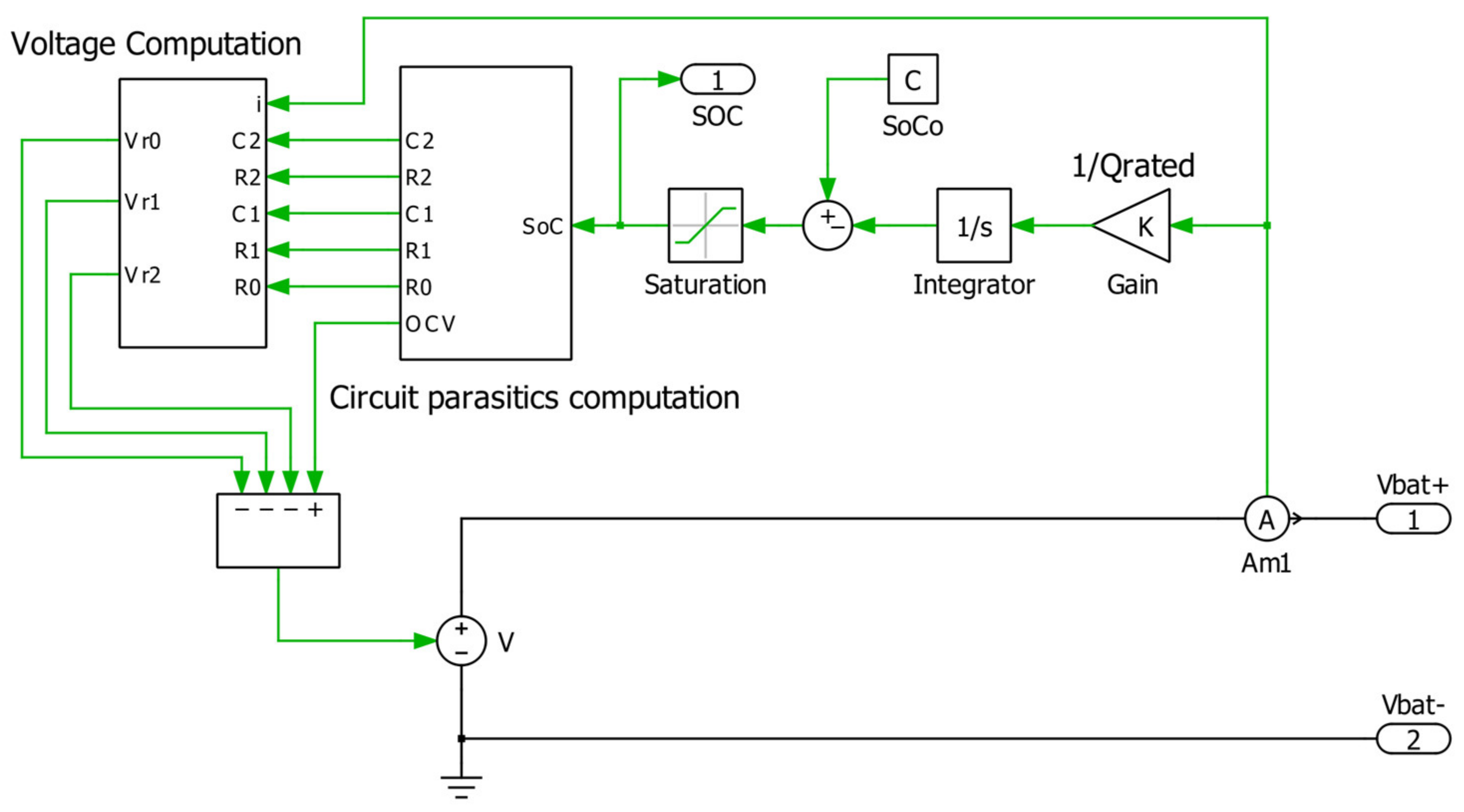
2.2. Battery Modeling

In the literature, three types of battery models are frequently investigated: empirical (or analytical), electrochemical, and equivalent circuit models. Equivalent circuit models are often preferred for power management control and BMS because they have a simple configuration and small number of parameters that are derived from experimental data describing the dynamic characteristics of the battery with acceptable accuracy [38]. Different battery equivalent circuit models exist in the literature, which have been proposed in [39,40,41,42]; however, the one chosen for this work is the model based on the second-order Thevenin equivalent circuit shown in Figure 8. The choice of this model is based on its simple, yet accurate-enough computational results.
The terminal voltage in the time domain is given by:
V b t = V O C t R s I b t V R t 1 t V R t 2
where VOC is the battery open circuit voltage, VRt1 is the voltage across resistor Rt1, VRt2 is the voltage across resistor Rt2, and Ib is the battery current. The SoC is computed based on the Coulomb counting technique. Here, the discharging current of the battery is measured and integrated over time to estimate the SoC [43,44]. This is given mathematically by the following equation:
S o C t = S o C t o + t o t o + τ I b a t d τ Q r a t e d    
where Qrated is the rated or nominal capacity of the battery (Ah). A Thevenin model is produced in PLECS, as shown in Figure 9, consisting of two subsystems which calculate the battery capacitances and resistances for various SoC, and with these values, the battery voltage is evaluated in the next subsystem. This battery model is used for the various simulations in this work as it gives fairly accurate results.

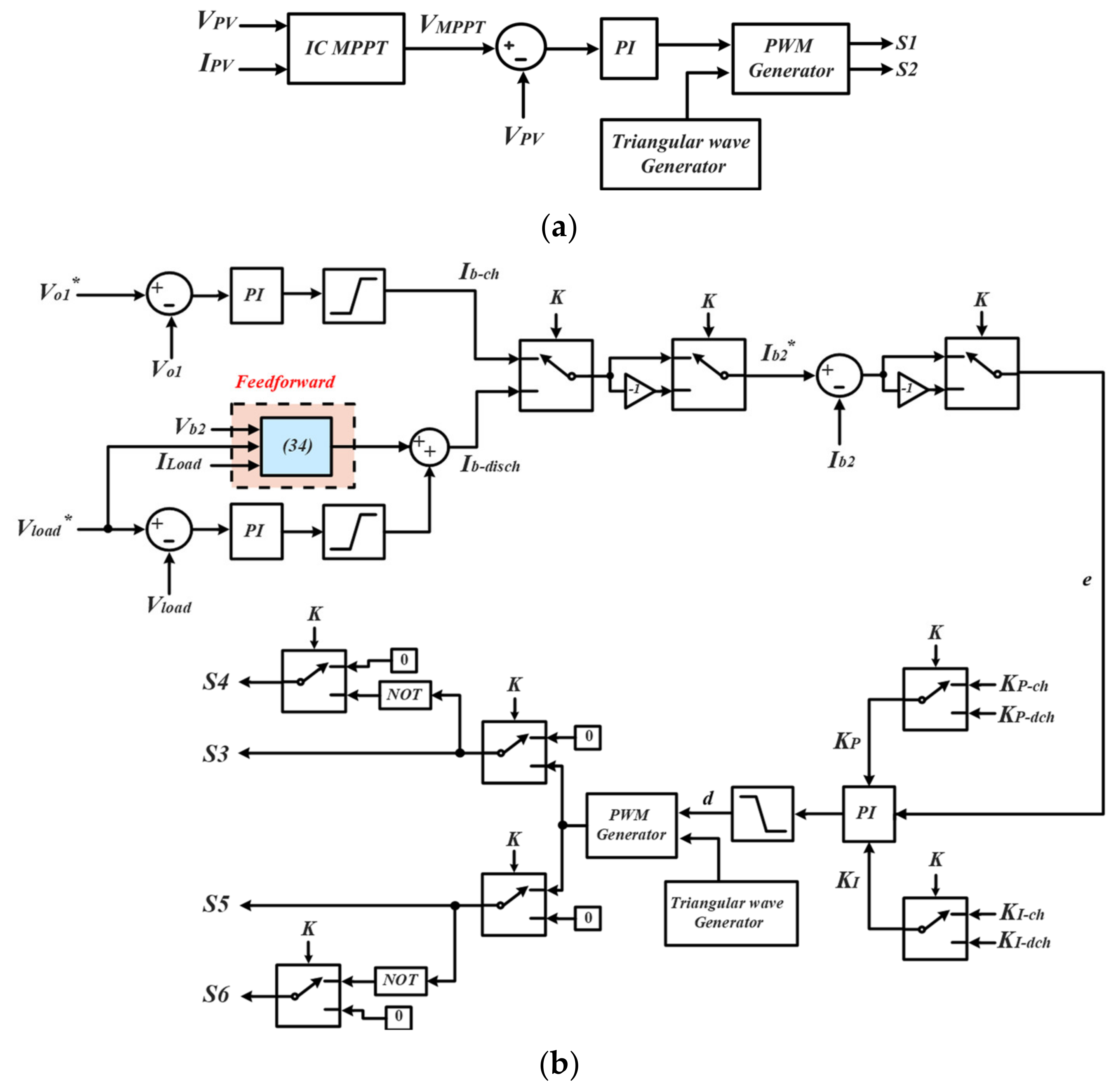
3. Power Management System

The control of power flow in the standalone system depends on the output power of the PV module, the load power demand, and the SoC of the BESS. The operation can be divided into six main modes (shown in Figure 10) which are explained below. Modes 1 to 5 correspond to periods where battery 2 is charged; consequently, converter U3 is shut down during these periods.
Mode 1: Ppv > Pbat2
In this mode, the extracted power from the PV module which is operating at MPPT is greater than the battery 2 power demand. Under this condition, the excess power is used to charge battery 1 provided that its SoC is within acceptable limits and that the power provided to the battery does not exceed its power limits which could potentially destroy it. In the case that the excess power is greater than battery 2 maximum power, the PV module is made to operate at some other point different from the MPPT point such that Ppv < Pmpp.
Mode 2: Ppv = Pbat2
In this mode, the output power from the PV panel is sufficient to provide the power needed by battery 2. Therefore, battery 1 is not charged.
Mode 3: Ppv < Pbat2and Pbat1> Pbat2
Here the output power of the PV module is not sufficient to provide the demanded battery 2 power, most probably due to low irradiance. Under these circumstances, battery 1 discharges through converter U2 to provide the needed power to battery 2.
Mode: 4 Ppv = 0 and Pbat1> Pbat2
This is the night mode operation of the PV module where no power is produced from it. Therefore, the stored energy in battery 1 is discharged to charge battery 2.
Mode 5: Shutdown mode
In this scenario, the PV module does not have enough power to provide to battery 2 (Ppv < Pbat2) and battery 1 state of charge is such that it cannot provide the remaining power (Pbat1 < Pbat2). In this case, converter U2 is completely switched OFF to prevent battery 2 from performing a deep discharge of battery 1 which could destroy it.
Mode 6: Battery 2 discharge mode
When this mode is activated, battery 2 discharges through converter U3 to provide power to the resistive load. During this period, converter U2 is completely shut down.

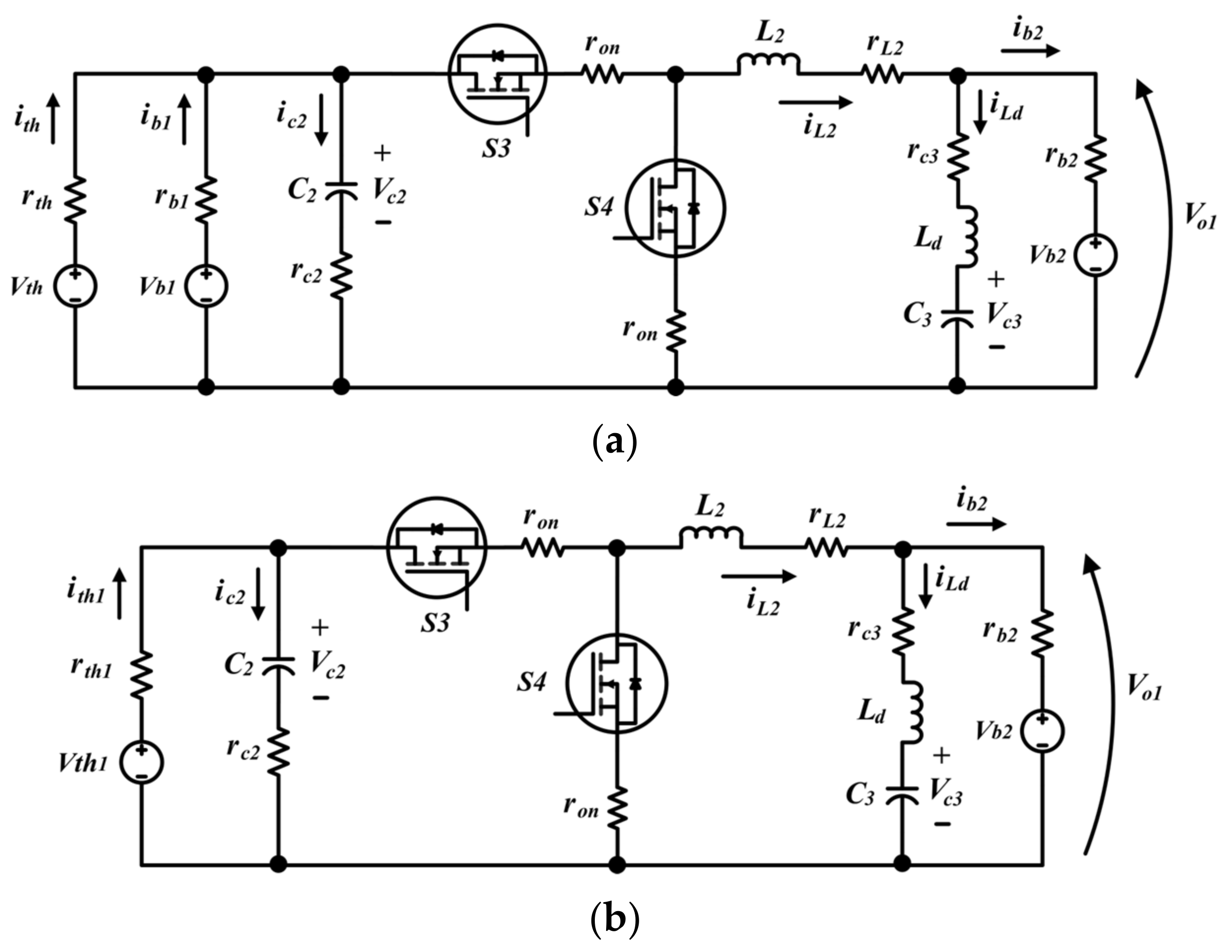
4. Small Signal Analysis of the Control System

The expanded version of the energy management system circuit diagram previously shown in Figure 3 is shown in Figure 11. This system introduces all the system components together with their corresponding parasitics. As seen, the DC–DC converters used for this application are buck converters. The energy flow profiles previously described in Section 3 can be applied to the schematic in Figure 11. In essence, the schematic represents an electric vehicle (battery 2) being charged through the use of solar PV, and once charged, it is discharged to supply other loads. There is also the presence of an external storage unit (battery 1) which acts as an energy source backup to the solar PV system.
The proposed control algorithm adopted for the circuit is shown in Figure 12. Figure 12a contains the control scheme for generating the control signals for converter 1 through MPPT control, while Figure 12b shows the control scheme for the generation of the signals for converter 2 and 3. The PWM signals generated for converter 2 and 3 comprise two different control paths. During the first phase, battery 2 charging voltage is controlled and a PI controller for this loop generates the reference battery current for battery 2, which is then used to generate the control logic for converter 1. During this period, converter 3 is completely shut down and non-operational. However, once the discharge signal (K) has been triggered, the control path and objective change to control the output load voltage. The output load voltage is then used to generate the input reference battery current for battery 2, which is used in generating the control signals for converter 3. During the battery 2 discharge phase, converter 2 is completely shut down. Furthermore, the discharge signal K could represent the battery 2 state of charge or battery 2 voltage; however, for this work, a simple 0/1 digital logic has been utilized for the control system proof-of-concept tests. A novel feedforward algorithm has also been introduced to improve the dynamic response of the system, especially in the presence of disturbances.

4.1. MPPT Control

The control of the PV side buck converter, shown in Figure 12a, is performed by implementing an MPPT controller to extract maximum power under any weather condition. In this work, the incremental conductance MPPT algorithm is adopted since it is more efficient than the perturb and observe algorithm [45]. The flow chart of the incremental conductance algorithm is shown in Figure 13. The MPPT controller generates the reference PV voltage, which is fed to a voltage control loop to regulate the PV voltage at a setpoint value.
The design of the PI controller, shown in Figure 12a, is performed by doing a small signal analysis of the PV side converter. The circuit used to perform the AC signal modeling is shown in Figure 14. In this circuit, the PV panel has been replaced by an equivalent voltage and series resistance whose values depend on the maximum power point of the PV: Req = Vmpp/Impp and Veq = Vmpp + Req Impp [46]. Also, Rin corresponds to the input resistance of the load-side buck converter seen by the PV source, and this depends on the duty ratio of the converter as given by the following equation:
R i n = R L M 2 ( D 2 )
where RL is the DC load resistance and M(D2) is the gain ratio of the load-side buck converter.
The buck converter shown in Figure 14 is assumed to be working in CCM. As such, there are two operating modes of the circuit: S1 = ON, S2 = OFF and S1 = OFF, S2 = ON. Also, the state variables x(t) are the inductor current and capacitor voltage (x(t) = {iL1(t), vC1(t)}), the input variables u(t) are the equivalent PV voltage and the battery voltage (u(t) = {Veq, Vb1}), and the output variable y(t) is the PV voltage (y(t) = Vpv(t)).
When S1 is ON and S2 is OFF, the state space equations are:
x 1 ˙ x 2 ˙ = 1 L 1 r c 1 C 1 R e q b r o n + r L 1 r b 1 a 1 L 1 1 r c 1 C 1 b R e q b 1 b A 1 x 1 x 2 + r c 1 C 1 b L 1 1 a L 1 1 b 0 B 1 V e q V b 1
y = v p v = r c 1 C 1 R e q b 1 r c 1 C 1 b C 1 x 1 x 2 + r c 1 C 1 b 0 E 1 V e q V b 1
where a = 1 + rb1/Rin and b = rc1C1 + ReqC1.
When S1 is OFF and S2 is ON, the state space equations are:
x 1 ˙ x 2 ˙ = 1 L 1 r o n + r L 1 r b 1 a 0 0 1 b A 2 x 1 x 2 + 0 1 a L 1 1 b 0 B 2 V e q V b 1
y = v p v = 0 1 r c 1 C 1 b C 2 x 1 x 2 + r c 1 C 1 b 0 E 2 V e q V b 1
Introducing small signal perturbations in the state variables and performing AC state space averaging over the entire switching period gives the following equations [47]:
d x ^ d t = A x ^ + B u ^ + [ A 1 A 2 X + ( B 1 B 2 ) U ] F d ^ y ^ = C x ^ + E u ^ + [ C 1 C 2 X + ( E 1 E 2 ) U ] G d ^
where A = A 1 D + A 2 1 D , B = B 1 D + B 2 1 D , C = C 1 D + C 2 1 D   a n d   E = E 1 D + E 2 1 D .
From the first equation shown in (15), the capacitor to duty ratio transfer function can be derived and is given as:
V ^ c s d ^ 1 s u = 0 = s I A 1 F ( 2 , 1 )
From (16), the PV-voltage-to-duty ratio transfer function can then be obtained and is given as:
V ^ p v s d ^ 1 s = 1 + s r c V c s d s u ^ = 0
An alternative expression for the PV-voltage-to-duty ratio transfer function can be obtained by using the second equation of (15) as shown:
V ^ p v s d ^ 1 s u ^ = 0 = C s I A 1 F + G

4.2. Battery 2 Charging Voltage and Current Control

The regulation of the battery voltage is performed by using buck converter 2. The equivalent circuit of this converter is shown in Figure 15a. As seen, the input to the converter is made up of two parallel voltage source branches with their series resistance. The first branch consists of the Thevenin equivalent voltage and Thevenin resistance of the PV side buck converter seen from the input of converter 2. The analysis can be further simplified by finding the Thevenin equivalent of the two input parallel voltage sources and their associated resistances. The simplified equivalent circuit is then shown in Figure 15b with the equivalent resistance and voltage given by:
r t h 1 = r t h / /   r b 1 V t h 1 = V t h r t h r t h + r b V t h V b 1
The values of the Thevenin equivalent resistance and voltage in Figure 15a can be determined by using the DC transformer model of the buck converter shown in Figure 16:
r t h = R e q + r o n + r L 1 D 1 + r L 1 + r o n 1 + D 1 V t h = D 1 V e q
Just like the previous case, the circuit in Figure 15b is assumed to be working in CCM. As such, there are two operating modes of the circuit: S3 = ON, S4 = OFF, and S3 = OFF, S4 = ON. Also, the state variables x(t) are the two inductor currents, the input capacitor voltage and the output capacitor voltage (x(t) = {iL1(t), iLd(t) vC2(t), vC3(t)}), the input variables u(t) are the Thevenin equivalent voltage and the battery voltage (u(t) = {Vb2, Vth1}), while the output variables y(t) are the output voltage and battery current (y(t) = {Vo1(t), ib2(t)}).
When S3 is ON and S4 is OFF, the state space equations are:
x 1 ˙ x 2 ˙ x 3 ˙ x 4 ˙ = 1 L 1 r c 1 C 1 u r o n + r L 1 r b 2 r b 2 L 1 1 L 1 1 + r c 1 C 1 u r t h 1 0 r b 2 L 2 r b 2 + r c 3 L 2 0 1 L 2 1 / u 0 1 u r t h 1 0 0 1 C 2 0 0 A 1 x 1 x 2 x 3 x 4 + 1 L 1 r c 1 C 1 u r t h 1 L 1 1 L 2 0 0 1 u r t h 1 0 0 B 1 V b 2 V t h 1
where u = C 1 1 + r c 1 r t h 1 , and
y = v o 1 i b 2 = r b 2 r b 2 0 0 1 1 0 0 C 1 x 1 x 2 x 3 x 4 + 1 0 0 0 E 1 V b 2 V t h 1
When S3 is OFF and S4 ON, the state space equations are given by:
x 1 ˙ x 2 ˙ x 3 ˙ x 4 ˙ = 1 L 1 r o n + r L 1 r b 2 r b 2 L 1 0 0 r b 2 L 2 r b 2 + r c 3 L 2 0 1 L 2 0 0 1 u r t h 1 0 0 1 C 2 0 0 A 2 x 1 x 2 x 3 x 4 + 1 L 1 0 1 L 2 0 0 1 u r t h 1 0 0 B 2 V b 2 V t h 1  
and
y = v o 1 i b 2 = r b 2 r b 2 0 0 1 1 0 0 C 2 x 1 x 2 x 3 x 4 + 1 0 0 0 E 2 V b 2 V t h 1
By introducing small ac perturbations to the state variables and averaging over the entire switching cycle, we obtain the equations given in (15) from which we obtain the control equations:
i ^ b 2 s d ^ 2 s u ^ = 0 = { C s I A 1 F + G } ( 2 , 1 )
v ^ o 1 s i ^ b 2 s d ^ 2 = 0 = r b 2 + 1 T s
T s = i ^ b 2 s v ^ b 2 s d ^ 2 = 0 = { C s I A 1 B + E } ( 2 , 1 )

4.3. Control of Battery 2 Discharge

The equivalent circuit of the system used to design the control algorithm during the discharge phase of battery 2 is shown in Figure 17. The input inductor (Ld) acts as a damper and eliminates oscillations that occur when there is a repeated change from battery charge to discharge. Therefore, it helps to maintain system stability ensuring that the Middlebrook criterion is obeyed. As previously mentioned, during the discharge phase of battery 2, converter 2 is completely shut down.
Again, the circuit in Figure 17 is assumed to be working in CCM. As such, there are two operating modes of the circuit: S5 = ON, S6 = OFF, and S5 = OFF, S6 = ON. Also, the state variables x(t) are the two inductor currents, the input capacitor voltage and the output capacitor voltage (x(t) = {iLd(t), iL3(t), vC3(t), vC4(t)}), the input variable u(t) is the battery voltage (u(t) = {Vb2}), while the output variable y(t) is the output voltage (y(t) = {VLoad(t)}).
When S5 is ON and S6 is OFF, the state space equations are:
y x 1 ˙ x 2 ˙ x 3 ˙ x 4 ˙ = 1 L d r b 2 + r c 3 r c 3 L d 1 L d 0 r c 3 L 3 1 L 3 r c 3 + r o n + r L 3 + r c 4 C 4 m 1 L 3 1 L 3 r c 4 C 4 m R L 1 1 C 3 1 C 3 0 0 0 1 m 0 1 m R L A 1 x 1 x 2 x 3 x 4 + 1 L d 0 0 0 B 1 V b 2
y = V L o a d = 0 r c 4 C 4 a 0 1 r c 4 C 4 m R L C 1 x 1 x 2 x 3 x 4
where m = C4(1 + rc4/RL).
When S5 is OFF and S6 is ON, the state space equations are:
x 1 ˙ x 2 ˙ x 3 ˙ x 4 ˙ = 1 L d r b 2 + r c 3 r c 3 L d 1 L d 0 0 1 L 3 r o n + r L 3 + r c 4 C 4 m 0 1 L 3 r c 4 C 4 m R L 1 1 C 3 0 0 0 0 1 m 0 1 m R L A 2 x 1 x 2 x 3 x 4 + 1 L d 0 0 0 B 2 V b 2
y = V L o a d = 0 r c 4 C 4 a 0 1 r c 4 C 4 m R L C 2 x 1 x 2 x 3 x 4
Equations (28)–(31) give the large signal model of the converter. The small signal model is obtained by perturbing the state variables in these equations over the entire switching cycle. Doing this, we obtain equations in the form of (15) from which the control equations are obtained as:
i ^ b 2 s d ^ 3 s u ^ = 0 = i ^ L d s d ^ 3 s u ^ = 0 = { C s I A 1 F } ( 1 , 1 )
v ^ L o a d s i ^ b 2 s = D s r c 3 L 3 + 1 L 3 C 3 ( s r c 4 C 4 + 1 ) m s + 1 m R L s 2 + s r c 4 C 4 + m r L 3 + r o n + D r c 3 m L 3 + D 2 L 3 C 4 + m R L r c 4 C 4 m R L L 3
In addition to the already-derived feedback control equations, a feedforward term is derived and added to the outer load voltage control loop to make the system more robust to disturbances. This feedforward term is based on the power balance between the input and output ports of the converter. Accordingly, the feed-forward expression is given by:
I b 2 _ e s t * = I L o a d V o 1 V L o a d *

5. Numerical Simulations

To investigate the dynamic behavior of the models developed and the control system proposed, numerical simulations are performed using the solar panel specifications in Table 1 and the system parameters in Table 2. The parasitic values of inductors and capacitors shown in Table 2 were chosen based on typical commercially available datasheet values.
Furthermore, MATLAB SISOTOOL is used to design the parameters of the PI controllers using the transfer functions derived in Section 4. The parameters of the PI controller are summarized in Table 3.
The power flow and energy management system are investigated by varying the irradiance and temperature of the PV module for 5 s as seen in Figure 18a. This variation brings about a change in the PV output power sent to the converters. During this period, battery 2 is charged at constant voltage values of 8 V, 9 V, 10 V, and 11 V. The power flow profiles obtained are shown in Figure 18b. We observe from Figure 18b that when the power demanded by battery 2 is such that it can be provided by the PV system alone, the backup energy source (battery 1) is charged, indicated by an increase in its state of charge. From Figure 18b, this process occurs during three time periods: 0–1 s, 1.5–2 s, and 3.5–5 s. On the other hand, when the demanded power from battery 2 cannot be provided solely by solar PV, then battery 1 starts to discharge to provide the additional power needed to charge battery 2. This process occurs during two intervals: 1–1.5 s and 2–3.5 s. In the battery model developed, negative power corresponds to the battery being charged and vice versa.
To evaluate the charge and discharge profile of battery 2, the K-signal is used, as shown in Figure 19a, where a ‘1’ stands for the charging action of the battery and a ‘0’ stands for the discharging action of the battery. We see from Figure 19a that battery 2 is charged at constant voltage values of 8, 9, 10, and 11 V for a period of 0.4 s. During this time, the control system controls both battery 2 voltage and current as observed in Figure 19b. Also, during this period, the load is not under control, showing that converter 3 is inactive. However, once battery 2 starts to discharge, the load voltage is controlled in steps of 9, 4, 7, and 5 V while simultaneously controlling the battery 2 current as observed in Figure 19b. By controlling the battery current during both charge and discharge cycles, we are improving the health of the battery, hence increasing its lifetime.
Figure 20 compares the control system with and without feedforward compensation in the presence of load and input voltage disturbances at t = 0.07 s and t = 0.1 s, respectively. When these disturbances occur, the load voltage disturbance is higher when there is no compensation and takes more time to return to the steady state voltage value of 9 V. A similar behavior is observed with the load current response. The feedforward term therefore improves the dynamic response of the system in terms of speed of response and undershoots.

6. Conclusions

Throughout this work, improved solar PV and two time-constant battery models have been provided and validated. The proposed system architecture is the key element for the development of NGs involving PV modules, where it is of fundamental importance to optimize the self-consumption of energy produced. Numerical simulations demonstrated how temperature and irradiance affect the output power of a PV module. Furthermore, the PV and battery models were then employed at a system level to charge an electric vehicle battery through a cascade of DC–DC buck converters. To control the charge and discharge of the EV battery, a novel control scheme was proposed, and comprehensive models of the buck converter at each stage of the energy conversion were provided. One peculiarity about the proposed control system is that the charge of battery 2 through converter 2 and its discharge through converter 3 is performed using a single current loop as opposed to two parallel loops traditionally employed for similar applications. The use of a single current loop greatly reduces the size of the controller. Furthermore, numerical simulations show how the solar PV was able to charge both the backup energy storage battery and the EV battery when it had sufficient power, whereas the backup energy storage was able to compensate for power shortage from the PV plant when the power demanded by the EV battery was greater than what the PV module could provide. Simulations further emphasized benefits of introducing a feedforward expression such as quicker response and reduced undershoots to compensate for system disturbances.

Author Contributions

Conceptualization, N.D. and A.A.N.; methodology, D.S.; formal analysis, A.A.N.; investigation, A.A.N.; writing—original draft preparation, A.A.N.; writing—review and editing, D.S., P.C. and N.D.; supervision, N.D.; funding acquisition, N.D. All authors have read and agreed to the published version of the manuscript.

Funding

This research was funded by the Italian “Ministero dell’Istruzione, dell’Università e della Ricerca—Programma Operativo Nazionale 2014–2020 (PON): AZIONE IV.5—Dottorati su tematiche Green del PON R&I 2014–2020”, and under the National Recovery and Resilience Plan (NRRP), Mission 4 Component 2 Investment 1.5—Call for tender No. 3277 of 12/30/2021 of Italian Ministry of University and Research funded by the European Union—NextGenerationEU. Project code: ECS00000033, Concession Decree No. 1052 of 23 June 2022 adopted by the Italian Ministry of University and Research, CUP D93C22000460001, Project title: Ecosystem for Sustainable Transition in Emilia-Romagna.

Data Availability Statement

The data presented in this work are available upon request from the corresponding author.

Conflicts of Interest

The authors declare no conflict of interest.

References

  1. Bhunia, M.; Gupta, R.; Subudhi, B. Cascaded DC-DC converter for a reliable standalone PV fed DC load. In Proceedings of the 2014 IEEE 6th India International Conference on Power Electronics (IICPE), Kurukshetra, India, 8–10 December 2014; pp. 1–6. [Google Scholar] [CrossRef]
  2. Mohapatra, D.; Padhee, S.; Jena, J. Design of Solar Powered Battery Charger: An Experimental Verification. In Proceedings of the 2018 IEEE International Students’ Conference on Electrical, Electronics and Computer Science (SCEECS), Bhopal, India, 24–25 February 2018; pp. 1–5. [Google Scholar] [CrossRef]
  3. Mirzaei, A.; Forooghi, M.; Ghadimi, A.A.; Abolmasoumi, A.H.; Riahi, M.R. Design and construction of a charge controller for stand-alone PV/Battery hybrid system by using a new control strategy and power management. Sol. Energy 2017, 149, 132–144. [Google Scholar] [CrossRef]
  4. Shaw, P.; Sahu, P.K.; Maity, S.; Kumar, P. Modeling and control of a battery connected standalone photovoltaic system. In Proceedings of the 2016 IEEE 1st International Conference on Power Electronics, Intelligent Control and Energy Systems (ICPEICES), Delhi, India, 4–6 July 2016; pp. 1–6. [Google Scholar] [CrossRef]
  5. Bhattacharyya, S.; Samanta, S. DC Link Voltage Control based Power Management Scheme for Standalone PV Systems. In Proceedings of the 2018 IEEE International Conference on Power Electronics, Drives and Energy Systems (PEDES), Chennai, India, 18–21 December 2018; pp. 1–5. [Google Scholar] [CrossRef]
  6. Chiang, S.J.; Shieh, H.; Chen, M. Modeling and Control of PV Charger System With SEPIC Converter. IEEE Trans. Ind. Electron. 2009, 56, 4344–4353. [Google Scholar] [CrossRef]
  7. Mahmood, H.; Michaelson, D.; Jiang, J. Control strategy for a standalone PV/battery hybrid system. In Proceedings of the IECON 2012—38th Annual Conference on IEEE Industrial Electronics Society, Montreal, QC, Canada, 25–28 October 2012; pp. 3412–3418. [Google Scholar] [CrossRef]
  8. Rahman, S.; Saha, S.; Islam, S.N.; Arif, M.T.; Mosadeghy, M.; Haque, M.E.; Oo, A.M. Analysis of Power Grid Voltage Stability with High Penetration of Solar PV Systems. IEEE Trans. Ind. Appl. 2021, 57, 2245–2257. [Google Scholar] [CrossRef]
  9. Garniwa, I.; Kuncoro, M.; Darussalam, R. Comparative Study for PV Power Stabilization Technology using Matlab Simulink. In Proceedings of the 2019 International Conference on Mechatronics, Robotics and Systems Engineering (MoRSE), Bali, Indonesia, 4–6 December 2019; pp. 112–117. [Google Scholar] [CrossRef]
  10. Zhao, J.; Iu, H.H.C.; Fernando, T.; An, L.; Lu, D.D.-C. Design of a non-isolated single-switch three-port DC-DC converter for standalone PV-battery power system. In Proceedings of the 2015 IEEE International Symposium on Circuits and Systems (ISCAS), Lisbon, Portugal, 24–27 May 2015; pp. 2493–2496. [Google Scholar] [CrossRef]
  11. Parsekar, S.; Chatterjee, K. A novel strategy for battery placement in standalone solar photovoltaic converter system. In Proceedings of the 2014 IEEE 40th Photovoltaic Specialist Conference (PVSC), Denver, CO, USA, 8–13 June 2014; pp. 2751–2756. [Google Scholar] [CrossRef]
  12. Gabbar, H.A.; Othman, A.M.; Abdussami, M.R. Review of Battery Management Systems (BMS) Development and Industrial Standards. Technologies 2021, 9, 28. [Google Scholar] [CrossRef]
  13. Okay, K.; Eray, S.; Eray, A. Development of Prototype Battery Management System for PV system. Renew. Energy 2022, 181, 1294–1304. [Google Scholar] [CrossRef]
  14. Spertino, F.; Ciocia, A.; Di Leo, P.; Malgaroli, G.; Russo, A. A smart battery management system for photovoltaic plants in households based on Raw Production Forecast. In Green Energy Advances; IntechOpen: London, UK, 2018. [Google Scholar] [CrossRef]
  15. Subashini, M.; Ramaswamy, M. A novel design of charge controller for a standalone solar photovoltaic system. In Proceedings of the 2016 3rd International Conference on Electrical Energy Systems (ICEES), Chennai, India, 17–19 March 2016; pp. 237–243. [Google Scholar] [CrossRef]
  16. Yang, Y.; Qin, Y.; Tan, S.-C.; Hui, S.Y.R. Efficient Improvement of Photovoltaic-Battery Systems in Standalone DC Microgrids Using a Local Hierarchical Control for the Battery System. IEEE Trans. Power Electron. 2019, 34, 10796–10807. [Google Scholar] [CrossRef]
  17. Deshmukh, S.; Thorat, A.R.; Korachagaon, I. Modelling and Analysis of PV Standalone System With Energy Management Scheme. In Proceedings of the 2020 IEEE International Conference on Electronics, Computing and Communication Technologies (CONECCT), Bangalore, India, 2–4 July 2020; pp. 1–5. [Google Scholar] [CrossRef]
  18. Xiao, W.; Ozog, N.; Dunford, W.G. Topology Study of Photovoltaic Interface for Maximum Power Point Tracking. IEEE Trans. Ind. Electron. 2007, 54, 1696–1704. [Google Scholar] [CrossRef]
  19. Stošović, M.A.; Dimitrijević, M.; Litovski, V. MPPT controller design for a standalone PV system. In Proceedings of the 2013 11th International Conference on Telecommunications in Modern Satellite, Cable and Broadcasting Services (TELSIKS), Nis, Serbia, 16–19 October 2013; pp. 501–504. [Google Scholar] [CrossRef]
  20. Chong, L.W.; Wong, Y.W.; Rajkumar, R.K.; Isa, D. Modelling and simulation of standalone PV systems with battery-supercapacitor Hybrid Energy Storage System for a rural household. Energy Procedia 2017, 107, 232–236. [Google Scholar] [CrossRef]
  21. Zakzouk, N.E.; Lotfi, R.A. Power Flow Control of a Hybrid Battery/Supercapacitor Standalone PV System under Irradiance and Load Variations. In Proceedings of the 2020 10th International Conference on Power and Energy Systems (ICPES), Chengdu, China, 25–27 December 2020; pp. 469–474. [Google Scholar] [CrossRef]
  22. Badpanda, S.; Dey, J.; Saha, T.K. Power Management and Control for PV-Battery-UC Standalone System. In Proceedings of the 2021 IEEE 4th International Conference on Computing, Power and Communication Technologies (GUCON), Kuala Lumpur, Malaysia, 24–26 September 2021; pp. 1–7. [Google Scholar] [CrossRef]
  23. Xiao, W.; Elnosh, A.; Khadkikar, V.; Zeineldin, H. Overview of maximum power point tracking technologies for photovoltaic power systems. In Proceedings of the IECON 2011—37th Annual Conference of the IEEE Industrial Electronics Society, Melbourne, Australia, 7–10 November 2011; pp. 3900–3905. [Google Scholar] [CrossRef]
  24. Harini, K.; Syama, S. Simulation and analysis of incremental conductance and Perturb and Observe MPPT with DC-DC converter topology for PV array. In Proceedings of the 2015 IEEE International Conference on Electrical, Computer and Communication Technologies (ICECCT), Coimbatore, India, 5–7 March 2015; pp. 1–5. [Google Scholar] [CrossRef]
  25. John, R.; Mohammed, S.S.; Zachariah, R. Variable step size Perturb and observe MPPT algorithm for standalone solar photovoltaic system. In Proceedings of the 2017 IEEE International Conference on Intelligent Techniques in Control, Optimization and Signal Processing (INCOS), Krishnankoil, India, 23–25 March 2017; pp. 1–6. [Google Scholar] [CrossRef]
  26. Mohapatra, A.; Nayak, B.; Saiprakash, C. Adaptive Perturb & Observe MPPT for PV System with Experimental Validation. In Proceedings of the 2019 IEEE International Conference on Sustainable Energy Technologies and Systems (ICSETS), Odisha, India, 26 February–1 March 2019; pp. 257–261. [Google Scholar] [CrossRef]
  27. Macaulay, J.; Zhou, Z. A Fuzzy Logical-Based Variable Step Size P&O MPPT Algorithm for Photovoltaic System. Energies 2018, 11, 1340. [Google Scholar] [CrossRef]
  28. Venkatramanan, D.; John, V. Dynamic Modeling and Analysis of Buck Converter based Solar PV Charge Controller for Improved MPPT Performance. In Proceedings of the 2018 IEEE International Conference on Power Electronics, Drives and Energy Systems (PEDES), Chennai, India, 18–21 December 2018; pp. 1–6. [Google Scholar] [CrossRef]
  29. Chtita, S.; Derouich, A.; El Ghzizal, A.; Motahhir, S. An improved control strategy for charging solar batteries in off-grid photovoltaic systems. Sol. Energy 2021, 220, 927–941. [Google Scholar] [CrossRef]
  30. Badreldien, M.M.; Abuagreb, M.; Allehyani, M.F.; Johnson, B.K. Modeling and Control of Solar PV System Combined with Battery Energy Storage System. In Proceedings of the 2021 IEEE Electrical Power and Energy Conference (EPEC), Virtual Conference, 22–31 October 2021; pp. 373–377. [Google Scholar] [CrossRef]
  31. Tamrakar, V.; Gupta, S.C.; Sawle, Y. Study of characteristics of single and double diode electrical equivalent circuit models of solar PV module. In Proceedings of the 2015 International Conference on Energy Systems and Applications, Pune, India, 30 October–1 November 2015; pp. 312–317. [Google Scholar] [CrossRef]
  32. Tutkun, N.; Gegin, K.; Sarma, N.; Salam, Z. Comparison of Typical PV Module Performances Based on the Circuit Models. In Proceedings of the 2018 IEEE PES Asia-Pacific Power and Energy Engineering Conference (APPEEC), Sabah, Malaysia, 7–10 October 2018; pp. 206–211. [Google Scholar] [CrossRef]
  33. Teyabeen, A.A.; Elhatmi, N.B.; Essnid, A.A.; Jwaid, A.E. Parameters Estimation of Solar PV Modules Based on Single-Diode Model. In Proceedings of the 2020 11th International Renewable Energy Congress (IREC), Hammamet, Tunisia, 29–31 October 2020; pp. 1–6. [Google Scholar] [CrossRef]
  34. Kar, S.; Banerjee, S.; Chanda, C.K. Stepwise Modelling and Analysis of A PV Module in Matlab Simulink. In Proceedings of the 2021 International Conference on Intelligent Technologies (CONIT), Hubli, India, 25–27 June 2021; pp. 1–5. [Google Scholar] [CrossRef]
  35. Nezami, M.M.; Sarwar, M. Characteristic modeling analysis and simulation of solar PV module. In Proceedings of the 2015 Annual IEEE India Conference (INDICON), New Delhi, India, 17–20 December 2015; pp. 1–6. [Google Scholar] [CrossRef]
  36. Ramos-Hernanz, J.; Lopez-Guede, J.M.; Zulueta, E.; Fernandez-Gamiz, U. Reverse saturation current analysis in photovoltaic cell models. WSEAS Trans. Power Syst. 2017, 12, 231–237. [Google Scholar]
  37. Sangsawang, V.; Chaitusaney, S. Modeling of photovoltaic module from commercial specification in datasheet. In Proceedings of the 2012 9th International Conference on Electrical Engineering/Electronics, Computer, Telecommunications and Information Technology, Phetchaburi, Thailand, 16–18 May 2012; pp. 1–4. [Google Scholar] [CrossRef]
  38. Liu, J.; Dong, Z.; Jin, T.; Liu, L. Recent Advance of Hybrid Energy Storage Systems for Electrified Vehicles. In Proceedings of the 2018 14th IEEE/ASME International Conference on Mechatronic and Embedded Systems and Applications (MESA), Oulu, Finland, 2–4 July 2018; pp. 1–2. [Google Scholar] [CrossRef]
  39. Roi, D.; Primon, A.; Rossella, M.; Ornato, M. 12V Battery modeling: Model development, simulation, and validation. In Proceedings of the 2017 International Conference of Electrical and Electronic Technologies for Automotive, Torino, Italy, 15–16 June 2017. [Google Scholar]
  40. Saldaña, G.; Martín, J.I.S.; Zamora, I.; Asensio, F.J.; Oñederra, O. Analysis of the Current Electric Battery Models for Electric Vehicle Simulation. Energies 2019, 12, 2750. [Google Scholar] [CrossRef]
  41. Hinz, H. Comparison of Lithium-Ion Battery Models for Simulating Storage Systems in Distributed Power Generation. Inventions 2019, 4, 41. [Google Scholar] [CrossRef]
  42. Chen, M.; Rincon-Mora, G.A. Accurate electrical battery model capable of predicting runtime and I-V performance. IEEE Trans. Energy Convers. 2006, 21, 504–511. [Google Scholar] [CrossRef]
  43. Susanna, S.; Dewangga, B.R.; Wahyungoro, O.; Cahyadi, A.I. Comparison of Simple Battery Model and Thevenin Battery Model for SOC Estimation Based on OCV Method. In Proceedings of the 2019 International Conference on Information and Communications Technology (ICOIACT), Yogyakarta, Indonesia, 24–25 July 2019; pp. 738–743. [Google Scholar] [CrossRef]
  44. Chang, W.-Y. The state of charge estimating methods for Battery: A review. ISRN Appl. Math. 2013, 2013, 953792. [Google Scholar] [CrossRef]
  45. Sridhar, H.; Meera, K.S. Study of grid connected solar photovoltaic system using real time digital simulator. In Proceedings of the 2014 International Conference on Advances in Electronics Computers and Communications, Bangalore, India, 10–11 October 2014; pp. 1–6. [Google Scholar] [CrossRef]
  46. Callegaro, L.; Ciobotaru, M.; Fletcher, J.E.; Rios, P.A.; Pagano, D.J. Design of cascaded control loop for solar power optimizer based on a buck-boost converter. In Proceedings of the 2016 IEEE 2nd Annual Southern Power Electronics Conference (SPEC), Auckland, New Zealand, 5–8 December 2016; pp. 1–6. [Google Scholar] [CrossRef]
  47. He, Q.; Zhao, Y. The design of controller of buck converter. In Proceedings of the 2010 International Conference on Computer Application and System Modeling (ICCASM 2010), Taiyuan, China, 22–24 October 2010; pp. 251–255. [Google Scholar] [CrossRef]
Figure 1. Topologies for coupling of battery storage to DC-link through bidirectional DC–DC converters: (a) DC load directly connected to the DC bus; (b) DC load connected to the DC bus through a DC–DC converter.
Electronics 12 04725 g001
Figure 2. Topologies for direct coupling of battery storage to DC-link: (a) DC load directly connected to the DC bus; (b) DC load connected to the DC bus using a DC–DC converter.
Electronics 12 04725 g002
Figure 3. PV system with battery storage in off-grid configuration.
Electronics 12 04725 g003
Figure 4. Equivalent circuits of PV module: (a) single diode model; (b) double diode model.
Electronics 12 04725 g004
Figure 5. PLECS model of PV module.
Electronics 12 04725 g005
Figure 6. PV module characteristics with changing irradiance and constant cell temperature of 25 °C: (a) I-V curve; (b) P-V curve.
Electronics 12 04725 g006
Figure 7. PV module characteristics with changing cell temperature and irradiance of 1000 W/m2. (a) I-V curve; (b) P-V curve.
Electronics 12 04725 g007
Figure 8. Thevenin equivalent circuit battery model.
Electronics 12 04725 g008
Figure 9. Thevenin equivalent circuit battery model made in PLECS.
Electronics 12 04725 g009
Figure 10. Operational modes of the PV standalone system: (a) mode 1; (b) mode 2; (c) mode 3; (d) mode 4; (e) mode 5; (f) mode 6.
Electronics 12 04725 g010
Figure 11. Electrical schematic of the proposed energy management system.
Electronics 12 04725 g011
Figure 12. Proposed control algorithm: (a) MPPT controller for PV-side converter; (b) controller for battery 2 charge and discharge control.
Electronics 12 04725 g012
Figure 13. Flow chart of incremental conductance MPPT algorithm.
Electronics 12 04725 g013
Figure 14. Equivalent circuit of PV-side buck converter.
Electronics 12 04725 g014
Figure 15. Equivalent circuit of load-side converter with converter 3 deactivated: (a) Complete equivalent circuit (b) Input-simplified equivalent circuit.
Electronics 12 04725 g015
Figure 16. DC transformer model of PV-side buck converter.
Electronics 12 04725 g016
Figure 17. The equivalent circuit of converter 3 used to discharge battery 2 with converter 2 deactivated.
Electronics 12 04725 g017
Figure 18. (a) Time variation in PV irradiance and temperature; (b) power flow profiles.
Electronics 12 04725 g018
Figure 19. (a) Load and battery 2 voltage during charge/discharge cycle; (b) battery 2 current during charge/discharge cycle.
Electronics 12 04725 g019
Figure 20. Load response with and without feedforward compensation. (a) Load voltage; (b) load current.
Electronics 12 04725 g020
Table 1. Specifications of the BJ Penn BJP300M-A solar panel at STC.
ParametersValue
Maximum power (Pmax)300 W
Voltage at maximum power (Vmp)36.6 V
Current at maximum power (Imp)8.12 A
Open circuit voltage (Voc)44.8 V
Short circuit current (Isc)8.69 A
Temperature coefficient of Voc (Kv)−0.4239%/°C
Temperature coefficient of Isc (Ki)0.0906%/°C
Diode ideality factor (n)1.1
Number of cells in series (Ns)72
Shunt resistance (Rsh)738 Ω
Series resistance (Rs)0.284 Ω
Table 2. System electrical parameters.
ParameterValue
Battery 1 nominal voltage (Vb1)24 V
Battery 2 nominal voltage (Vb2)12 V
Switching frequency (Fsw)100 kHz
Inductances (L1, L2, L3, Ld)460 µH, 400 µH, 200 µH, 8 µH
Inductor parasitic resistances (rL1, rL2, rL4)60 mΩ, 70 mΩ, 50 mΩ
Capacitances (C1, C2, C3, C4)100 µF, 150 µF, 400 µF, 200 µF,
Capacitor parasitic resistances (rc1, rc2, rc3, rc4)50 mΩ, 50 mΩ, 40 mΩ, 60 mΩ
Load resistance (RL)3 Ω
Table 3. Controller parameters.
KpKiPMBW
MPPT voltage controller−0.258−79260°1.2 kHz
Load voltage controller15.543031.772°3 kHz
Battery 2 voltage charge controller−1.918−636965°2.5 kHz
Battery 2 current charge controller0.249566.950°800 Hz
Battery 2 current discharge controller0.51250.655°600 Hz
Disclaimer/Publisher’s Note: The statements, opinions and data contained in all publications are solely those of the individual author(s) and contributor(s) and not of MDPI and/or the editor(s). MDPI and/or the editor(s) disclaim responsibility for any injury to people or property resulting from any ideas, methods, instructions or products referred to in the content.

