


Distributed, Dynamic and Recursive Planning for Holonic Multi-Agent Systems: A Behavioural Model-Based Approach
 , ,
, ,
Abstract
:
1. Introduction
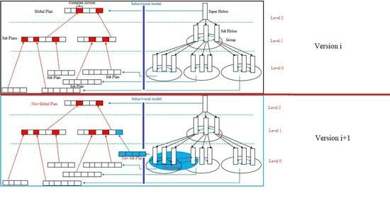
- The behaviour and structure of the holonic agent change over time to achieve new goals and adapt to the changing environment. This adaptation is ensured by the fact that each agent in the holonic agent can obtain new roles and new capabilities and introduce new interactions with other members during its lifetime [35]. On this basis, the plans generated to enable the holonic agent to achieve its first goals, defined in its first version, become insufficient for the new goals that have been introduced. Therefore, there is a need to generate new plans that enable the holonic agent to achieve these new goals.
- The global objective of the holonic agent, for which we want to generate plans, is decomposed hierarchically and recursively into a set of sub-objectives. Each sub-goal is supported by a group of roles played by the members (or sub-agents) of the holonic agent to achieve it. In this case, the planning problem in HMAS is composed of subproblems linked together recursively. Indeed, the generation of plans amounts to generating, in the first step, the sub-plans that allow the members of the holonic agent to reach the sub-objectives. The global plan will then be generated recursively by linking the sub-plans and considering the dependency that exists between them.
2. Related Works
- Torreño, A. et al. [40] introduced a general-purpose MAP architecture intended to address issues with any level of coupling when there is insufficient information. Agents in the MAP-proposed paradigm share only the knowledge that is necessary and that directly impacts other agents, preserving a distributed understanding of the task. Through the use of an iterative refinement planning process and single-agent planning technology, agents are able to complete MAP tasks.
- Daniel Borrajo and Susana Fernández [41] proposed a distributed approach and a centralised approach for MAP. In the first approach, agents receive prior agents’ plans, goals, and states to iteratively solve problems. They create new plans using the plans of earlier agents and they then distribute the new plans and some obscured private data to subsequent agents. The second approach has agents that create an obfuscated version of their problems in order to preserve their privacy, and then they present it to another agent that handles centralised planning.
- Jan Tožička et al. [42] proved the theoretical limits of strong privacy-preserving planning based on the most common MAP paradigms, such as distributed state space search. They also proposed a more refined definition of strong privacy, where some aspects of the problem are known as priori, and only the details remain strongly private.
- Jan Tožička et al. [43] developed a MAP framework for solving classical planning tasks for cooperative agents with private information. The objective is to minimise planning time, maximise the quality of the plans, and maximise the level of privacy between agents. The main motivation for these systems is to be able to use any current state-of-the-art planner as a basic solution to the problem (planner-independent).
- In Dehimi et al. [44], we proposed a new distributed dynamic planning approach based on constraint satisfaction that can consider the satisfaction of the constraints in all new versions of generated plans. As part of the proposed approach, each agent generates a new plan every time an agent’s set of planned actions changes due to unforeseen changes in the environment. For this, the approach ensures the correct placement of all new actions brought about by modifications in the new plan, maintaining the satisfaction of the constraints. The method employs a genetic algorithm, where the fitness function is established following the requirements that must be met.
- Leonardo Henrique et al. [45], developed a domain-independent statistical framework to assess recovery solutions in dynamic situations. The number of agents, goals, actions, failure probability, and the extent of agent connection were all varied in the authors’ simulation studies to validate the suggested methodology. Plan length and planning time are two indicators of evaluation. The findings demonstrate that replanning produces plans with fewer steps than fixing and that repairing planning time is lower with at least 94% certainty. The authors examined plan recovery solutions in dynamic multi-agent environments and showed that while repairing produces better results quickly, replanning produces superior plans since the length of the final plan is directly connected with the likelihood of failure.
3. Basic Concepts of Holonic Multi-Agent Systems
- Production groups are instances of organisations that describe how members interact and coordinate to meet the objectives and tasks assigned to their super-holon. The definition of these organisations depends on the problem being addressed.
- The holonic group is an instance of the holonic organisation that specifies how the members are organised to manage the super-holon in terms of the distribution of authority and power. It consists of five roles, qualified as holonic roles, namely Head (in charge of the administration of the super-holon), Representative (acts as an interface between the inside and the outside of the super-holon), Part (in charge of the execution of the tasks assigned to them by the Heads), MultiPart (in charge of the identification of members shared between several super-holons), and Stand-Alone (represents the status attributed to the nonmember holons to manage the recruitment of new members within a super-holon).
4. Multi-Agent Planning for Holonic Multi-Agent Systems
- Generation of sub-plans: This phase consists of generating, for each group Gikt (group k of level i at time t), the sub-plans of actions SPikt (sub-plans generated for the group k of level i at time t) to be executed at time t, by the members who play roles in this group, in order to solve the planning sub-problem Πikt (sub-problem associated with the group k of level i at time t) associated with this group and to enable it to achieve its objectives (the sub-objectives associated with this group). The generation of the sub-plans of each group Gik is carried out by the member who plays the Head holonic role in this group AHeadikt (the agent who plays the Head role in group k of level i at time t). For this purpose, each member AHeadikt, responsible for generating the plans of the Gikt group, uses the sequence diagram and the activity diagram of this group to determine the possible behaviour scenarios that allow it to wait for the subgoals of its group and to solve the planning sub-problem Πikt associated with the latter. Indeed, it uses the sequence diagram of this group to determine the interaction scenarios that need to be executed between the members who play roles in this group to achieve the subgoals of the group. It also uses the activity diagram of this group to determine the role actions that need to be performed by the members playing roles in this group by responding to these interactions. The order of these actions represents a sub-plan that can solve the planning sub-problem Πikt associated with the Gikt group.
- Generation of the global plan: This phase consists of linking, according to the hierarchical and behavioural dependence which exists between the roles of the groups of the different levels, the sub-plans SPikt obtained for each group in the first phase. This is performed in order to obtain a global action plan GPt (global plans of the holonic agent at time t). Its execution allows the holonic agent to solve the planning problem Πt associated with it and to achieve the global goal. Generation of the global plan is ensured by the member who plays the holonic role Head in the top-level group AHeadnt (the agent who plays the role Head in the top-level group n at time t). To do this, it recursively replaces the complex actions of each SPikt sub-plan, generated in the first phase, with the SPi−1kt of the lower-level groups (I − 1) that were at the origin of the publication of the services that implement the capabilities required by these complex actions.
4.1. The Formal Definition of Πt
- ✓
- Πikt = {Gikt, Hikt, N0ik, Nfik}, in which the definitions are as follows:
- -
- Gikt represents the group k of level i at time t.Gikt = {Rikj}/1≤j≤a, where Rikj represents the role j of the group k of level i.Rikj = {αikjl}/1≤l≤b, where αikjl represents the action l of role j of group k of level i. It can take two values:
- Sαikjl in case it represents a simple action implemented directly in the Rikj.
- Cαikjl in the case where it represents a complex action extracted as an ability implemented by a lower-level group. In this case, Cαikjl = Πi−1mt represents the planning problem associated with the group m of levels i − 1 at time t that implements the capacity of the action Cαikjl.
- -
- Hikt represents the set of member holons that play roles in group k of level i at time t.
- -
- N0ik represents the initial state of the sub-planning problem Πikt.
- -
- Nfik is the set of final states of the sub-planning problem Πikt.
- ✓
- N0 represents the initial state of the global planning problem Πt.
- ✓
- Nf is the set of final states of the global planning problem Πt.
4.2. The Formal Definition of Graphikt
- ▪
- Pj represents a path j in the graph associated with the scenario Sj. Each path Pj is defined as follows:Pj = {n0, SN, CN, njf}, in which the definitions are as follows:
- ▪
- n0 is the initial node representing the initial state of the planning sub-problem Πikt (the precondition of scenario Sj corresponding to Pj).
- ▪
- njf is the final node of the path j representing one of the final states of the planning sub-problem Πikt (the postconditions of the scenario Sj corresponding to Pj).
- ▪
- SN is the set of simple nodes that contain simple actions (implemented directly in the agent’s role) of the path Pj where each node nq belongs to SN is defined as follows: nq = <Agent_T, Activitynq>, in which the definitions are as follows:
- Agent_T is the receiver of the interaction represented by node nq.
- Activitynq represents the set of simple actions nαikql to be executed, because of the interaction represented by node nq, by the receiving agent.
- ▪
- CN is the set of nodes that contain complex actions (extracted as capabilities implemented by a lower-level group) of the path Pj, where each node nq belongs to CN is defined as follows: nq = <Agent_T, Graphi−1mt>, in which the definitions are as follows:
- Agent_T is the receiver of the interaction represented by node nq.
- Graphi-1mt represents the lower-level graphs that implement the complex actions Cαikjl of node nq.
4.3. Dynamic Generation of Plans
| Algorithm 1: Sub-plans_Generation |
 |
| Algorithm 2: Gplans_Generation. |
 |
5. Case Study
5.1. Presentation of the Transport Planning System
- G4 “Local Transport” (LT) is responsible for processing local requests: (a) receiving local transport requests from “Distribution Orientation”, (b) performing local transport tasks, and (c) generating a local transport report.
- G5 “Transport Orientation” (TO) is responsible for receiving and directing requests: (a) receiving transport requests from different cities, (b) checking requests, (c) locating requests, (d) classifying requests, (e) sending the transport request to (LT) and/or (DT), and (f) receiving execution reports from (LT) and/or (DT).
- G8 “Distance Transport” (DT) is responsible for processing distance requests: (a) receiving distance transport requests from “Distribution Orientation”, (b) executing distance transport tasks, and (e) generating the distance transport report.
- LT Interface: in charge of receiving local requests.
- Taxi: in charge of executing requests that require a taxi.
- Bus: in charge of executing requests that require a bus.
- Tram: in charge of executing requests that require a tram.
5.2. Application of Our Approach to the V0 Version of the Holonic Agent
5.2.1. Generation of Sub-Plans for V0
- Generation of the graph of each group: In this phase, the member who plays the head holonic role in each group transforms the sequence diagram and the activity diagram of its group into a graph. As part of the process of creating this graph, an intermediate step is taken in which the sequence diagram and the activity diagram are first converted into an XML file. This will make it easier to create and populate the various graph nodes. The following figures (Figure 4, Figure 5, Figure 6, Figure 7, Figure 8, Figure 9, Figure 10, Figure 11, Figure 12, Figure 13, Figure 14 and Figure 15) show (i) the sequence and activity diagrams of each group. These diagrams are extensions of UML for modelling HMAS defined in the ASPECS methodology [38]. (ii) The graphs obtained from the transformation of these diagrams. In these graphs, the nodes shown in red represent a graph that concerns the lower level.
- Generation of the sub-plans of each group: In this phase, the member who plays the Head holonic role in each group applies the algorithm for generating the sub-plans presented in the previous section to the graph of the latter. Table 1 represents the sub-plans obtained for each group. Each sub-plan represents a sequence of actions, each of which is defined by its identifier, the role in which it is included, and the holon that plays this role.
5.2.2. Generation of Global Plans for V0
5.3. Application of Our Approach to the New V1 Version of the Holonic Agent
5.3.1. Generation of Sub-Plans for V1
- Generation of the graph of each group affected by the change: the following figures (Figure 17, Figure 18, Figure 19, Figure 20, Figure 21 and Figure 22) show the sequence diagram and activity diagram of the groups involved in the change and the graph obtained from the transformation of these diagrams.
- Generation of sub-plans for each group affected by the change: the following table (Table 3) represents the sub-plans obtained for the groups affected by the changes (G1 and G8).
5.3.2. Generation of Global Plans for V1
5.4. Developed Tool
5.5. Discussion and Limitations
- The dynamic generation of plans for each newly developed version Vt of the holonic agent allows the implication of the new behaviours (acquired following the acquisition of new roles, new capacities, and the introduction of new interactions between the members of the holonic agent) in the new plans of the holonic agent. This allows it to solve the new planning problem Πt associated with its new version Vt for which the plans of the present version have become obsolete. As a result, the method may be very useful for open and complex multi-agent systems.
- The technique adopted for the generation of the plans, which consists of generating sub-plans for each group of the holonic agent and linking them to obtain the global plan, makes it possible to (i) simplify the planning problem following its decomposition into subproblems and (ii) minimise the generation time of the global plans following the possibility of generating the sub-plans in parallel. Consequently, the size of the system does not affect the calculation of the time required to generate the plans.
- The use of the sequence and activity diagrams of each group for the generation of its sub-plans has made it possible (i) to automate the generation of these sub-plans and consequently the generation of the global plan. As a result, the method can be easily adapted for multi-agent software that uses models in the analysis and design phases. (ii) To generate all possible sub-plans for each sub-objective (and consequently the generation of all possible global plans), giving the holonic agent the possibility to choose the most suitable plan with its constraints and conditions when executing the plans. (iii) To introduce, for each version of the holonic agent, a strong link between the real behaviour of each group (presented by the group’s sub-plans) and its behavioural model (presented by the group’s sequence and activity diagrams). This indirectly ensures an emergence control of the global behaviour of each version of the holonic agent.
6. Conclusions
Author Contributions
Funding
Data Availability Statement
Conflicts of Interest
References
- Ghallab, M.; Nau, D.; Traverso, P. Automated Planning: Theory and Practice; Elsevier: Amsterdam, The Netherlands, 2004. [Google Scholar]
- Blum, A.L.; Furst, M.L. Fast planning through planning graph analysis. Artif. Intell. 1997, 90, 281–300. [Google Scholar] [CrossRef]
- Nguyen, X.; Kambhampati, S. Reviving partial order planning. In Proceedings of the 17th International Joint Conference on Artificial Intelligence, IJCAI’01, Seattle, WA, USA, 4–10 August 2001; pp. 459–466. [Google Scholar]
- Hoffmann, J.; Nebel, B. The FF planning system: Fast plan generation through heuristic search. J. Artif. Intell. Res. 2001, 14, 253–302. [Google Scholar] [CrossRef]
- Richter, S.; Westphal, M. The LAMA planner: Guiding cost-based anytime planning with landmarks. J. Artif. Intell. Res. 2010, 39, 127–177. [Google Scholar] [CrossRef]
- Edelkamp, S.; Kissmann, P. GAMER: Bridging planning and general game playing with symbolic search. In Proceedings of the Booklet of the 6th International Planning Competition, Sydney, Australia, 14–18 September 2008. [Google Scholar]
- Haslum, P. Improving heuristics through relaxed search—An analysis of TP4 and HSP*a in the planning competition. J. Artif. Intell. Res. 2006, 25, 233–267. [Google Scholar] [CrossRef]
- Blythe, J. An overview of planning under uncertainty. AI Mag. 1999, 20, 37–54. [Google Scholar]
- Baki, B.; Bouzid, M.; Ligeza, A. Generating Low Cost Plans under Uncertainty and Temporal Constraints. In Proceedings of the 17th IEEE International Conference on Tools with Articial Intelligence (ICTAI 2005), Hong Kong, China, 14–15 November 2005; pp. 531–536. [Google Scholar]
- Albore, A.; Ramírez, M.; Geffner, H. Effective Heuristics and Belief Tracking for Planning with Incomplete Information. Proc. Int. Conf. Autom. Plan. Sched. 2011, 21, 2–9. [Google Scholar] [CrossRef]
- Alban, G.; Enrico, S. Intelligent belief state sampling for conformant planning. In Proceedings of the 26th International Joint Conference on Artificial Intelligence (IJCAI’17), Melbourne, Australia, 19–25 August 2017; AAAI Press: Washington, DC, USA, 2017; pp. 4317–4323. [Google Scholar]
- Ronen, B.; Guy, S. A multi-path compilation approach to contingent planning. In Proceedings of the Twenty-Sixth AAAI Conference on Artificial Intelligence (AAAI’12), Toronto, ON, Canada, 22–26 July 2012; AAAI Press: Washington, DC, USA, 2012; pp. 1868–1874. [Google Scholar]
- Muise, C.; Belle, V.; McIlraith, S. Computing Contingent Plans via Fully Observable Non-Deterministic Planning. Proc. AAAI Conf. Artif. Intell. 2014, 28. [Google Scholar] [CrossRef]
- Van Beek, P.; Chen, X. CPlan: A Constraint Programming Approach to Planning. In Proceedings of the 16th National Conference on Artificial Intelligence (AAAI-99), Orlando, FL, USA, 18–22 July 1999; pp. 585–590. [Google Scholar]
- Charles, R. About Bayesian Belief Networks; MIT Press: Cambridge, MA, USA, 2004. [Google Scholar]
- De Weerdt, M.; Clement, B. Introduction to planning in multiagent systems. Multiagent Grid Syst. 2009, 5, 345–355. [Google Scholar] [CrossRef]
- Alessandro, T.; Sofia, S.; Luca, I.; Fabio, P. A formalization of multi-agent planning, with explicit agent representation. In Proceedings of the ACM SAC Conference (SAC’23), Tallinn, Estonia, 27–31 March 2023; ACM: New York, NY, USA, 2023. [Google Scholar] [CrossRef]
- Moreira, L.H.; Ralha, C.G. Evaluation of Decision-making Strategies for Robots in Intralogistics Problems Using Multi-agent Planning. In Proceedings of the 2021 IEEE Congress on Evolutionary Computation (CEC), Kraków, Poland, 28 June–1 July 2021; pp. 1272–1279. [Google Scholar] [CrossRef]
- Xu, R.; Zhao, Y.; Li, Z.; Zhu, S.; Liang, Z.; Gao, Y. Hierarchical multi-agent planning for flexible assembly of large-scale lunar facilities. Adv. Eng. Inform. 2023, 55, 101861. [Google Scholar] [CrossRef]
- Chen, S.-T.; Ermiş, G.; Sharpanskykh, A. Multi-agent planning and coordination for automated aircraft ground handling. Robot. Auton. Syst. 2023, 167, 104480. [Google Scholar] [CrossRef]
- Lee, M.; Jang, S.; Cho, W.; Lee, J.; Lee, C.; Kim, S.H. A proposal on multi-agent static path planning strategy for minimizing radiation dose. Nucl. Eng. Technol. 2023; in press. [Google Scholar] [CrossRef]
- Zheng, Y.; Tu, X.; Yang, Q. Optimal Multi-Agent Map Coverage Path Planning Algorithm. In Proceedings of the Chinese Automation Congress (CAC), Shanghai, China, 6–8 November 2020; pp. 6055–6060. [Google Scholar] [CrossRef]
- Edmund, H.; Victor, L. Partial global planning: A coordination framework for distributed hypothesis formation. IEEE Trans. Syst. Man Cybernet. 1991, 21, 1167–1183. [Google Scholar]
- David, E.; Wilkins, L. A multiagent planning architecture. In Proceedings of the 4th International Conference on Artificial Intelligence Planning Systems (AIPS’98), Pittsburgh, PA, USA, 7–10 June 1998; pp. 154–162. [Google Scholar]
- Keith, D.; Victor, R. Generalizing the partial global planning algorithm. Int. J. Coop. Inf. Syst. 1992, 2, 319–346. [Google Scholar]
- Michael, W.; Marie, D. Controlling communication in distributed planning using irrelevance reasoning. In Proceedings of the 15th National Conference on Artificial Intelligence (AAAI’98), Madison, WI, USA, 26–30 July 1998; pp. 868–874. [Google Scholar]
- Jeffrey, S.; Edmund, H. Efficient mechanisms for multiagent plan merging. In Proceedings of the 3rd Conference on Autonomous Agents and Multiagent Systems (AAMAS’04), New York, NY, USA, 19–23 July 2004; pp. 1342–1343. [Google Scholar]
- Marie, D.; Michael, W. Coordinating a distributed planning system. AI Mag. 1999, 20, 45–53. [Google Scholar]
- Eithan, E.; Jeffrey, S. Divide and conquer in multi-agent planning. In Proceedings of the 12th National Conference on Artificial Intelligence (AAAI’94), Seattle, WA, USA, 31 July–4 August 1994; pp. 375–380. [Google Scholar]
- Eithan, E.; Jeffrey, S. A heuristic technique for multi-agent planning. Ann. Math. Artif. Intell. 1997, 20, 13–67. [Google Scholar]
- Craig, B.; Ronen, B. Partial-order planning with concurrent interacting actions. J. Artif. Intell. Res. 2001, 14, 105–136. [Google Scholar]
- Dehimi, N.E.H.; Guerram, T.; Tolba, Z. A new approach for coordinating generated agents’ plans dynamically. Multiagent Grid Syst. 2022, 18, 219–239. [Google Scholar] [CrossRef]
- Cox, J.; Durfee, E. Efficient and distributable methods for solving the multiagent plan coordination problem. Multiagent Grid Syst. 2009, 5, 373–408. [Google Scholar] [CrossRef]
- Jomi, F.H.; Jaime, S.; Olivier, B. S-Moise+: A Middleware for developing Organised Multi-Agent Systems. In Coordination, Organizations, Institutions, and Norms in Multi-Agent Systems; Springer: Berlin/Heidelberg, Germany, 2005. [Google Scholar] [CrossRef]
- Rodriguez, S.; Hilaire, V.; Gaud, N.; Galland, S.; Koukam, A. Holonic Multi-Agent Systems. In Self-Organising Software: From Natural to Artificial Adaptation—Natural Computing; Springer: Berlin/Heidelberg, Germany, 2011; Chapter 11; pp. 238–263. [Google Scholar]
- Koestler, A. The Ghost in the Machine; Hutchinson: London, UK, 1967. [Google Scholar]
- Cossentino, M.; Galland, S.; Gaud, N.; Hilaire, V.; Koukam, A. An organizational approach to engineer emergence within holarchies. Int. J. Agent-Oriented Softw. Eng. 2010, 4, 304–329. [Google Scholar] [CrossRef]
- Cossentino, M.; Gaud, N.; Hilaire, V.; Galland, S.; Koukam, A. ASPECS: An agent-oriented software process for engineering complex systems—How to design agent societies under a holonic perspective. Auton. Agents Multi-Agent Syst. 2010, 20, 260–304. [Google Scholar] [CrossRef]
- Rodriguez, S. From Analysis to Design of Holonic Multi-Agent Systems: A Framework, Methodological Guidelines and Applications. Ph.D. Thesis, Université de Technologie de Belfort Montbéliard, Belfort, France, 2005. [Google Scholar]
- Torreño, A.; Onaindia, E.; Sapena, Ó. A flexible coupling approach to multi-agent planning under incomplete information. Knowl. Inf. Syst. 2014, 38, 141–178. [Google Scholar] [CrossRef]
- Borrajo, D.; Fernández, S. Efficient approaches for multi-agent planning. Knowl. Inf. Syst. 2019, 58, 425–479. [Google Scholar] [CrossRef]
- Jan, T.; Michal, Š.; Antonín, K. The limits of strong privacy preserving multi-agent planning. In Proceedings of the 27th International Conference on Automated Planning and Scheduling (ICAPS’17), Pittsburgh, PA, USA, 18–23 June 2017; pp. 221–229. [Google Scholar]
- Tozicka, J.; Jakubuv, J.; Komenda, A. PSM-based planners description for CoDMAP 2015 competition. In Proceedings of the Competition of Distributed and Multi-Agent Planners (CoDMAP’15), Jerusalem, Israel, 7 June 2015; pp. 29–32. [Google Scholar]
- Dehimi, N.E.H.; Guerram, T.; Tolba, Z.; Mokhati, F. A Novel Distributed Dynamic Planning Approach Based On Constraint Satisfaction. Multiagent Grid Syst. 2018, 14, 243–261. [Google Scholar] [CrossRef]
- Moreira, L.H.; Ralha, C.G. Method for evaluating plan recovery strategies in dynamic multi-agent environments. J. Exp. Theor. Artif. Intell. 2022, 35, 1225–1249. [Google Scholar] [CrossRef]
- Rodriguez, S.; Nicolas, G.; Vincent, H.; Stephane, G.; Koukam, A. An analysis and design concept for self-organization in Holonic Multi-Agent Systems. In Proceedings of the 4th International Workshop on Engineering Self-Organizing Applications (ESOA’06), Hakodate, Japan, 9 May 2006. [Google Scholar]
- Rodriguez, S.; Gaud, N.; Galland, S. SARL: A general-purpose agent-oriented programming language. In Proceedings of the 2014 IEEE/WIC/ACM International Conference on Intelligent Agent Technology, Washington, DC, USA, 11–14 August 2014. [Google Scholar]
- Tan, R.K.; Bora, Ş. Exploiting of Adaptive Multi Agent System Theory in Modeling and Simulation: A Survey. J. Appl. Math. Comput. (JAMC) 2018, 1, 21–26. [Google Scholar] [CrossRef]


| Sub-plansG1 | Plan 1: H1[R1.G5, R1.A2: failed request]. |
| Plan 2: H1[R1.G5], H2[R2.G4], H1[R1.A9: service terminated]. | |
| Sub-plansG4 | Plan 1: H6[R6.A13: Send transport request], H7[R7.A10: move LV1, R7.A11: stop LV1, R7.A12: get down travellers LV1]. |
| Plan 2: H6[R6.A13: Send transport request], H7[R7.A10: move LV1, R7.A11: stop LV1, R7.A12: get down travellers LV1], H8[R8.A10: move LV3, R8. A11: stop LV3, R8.A12: get down travellers LV3]. | |
| Plan 3: H6[R6.A13: Send transport request], H7[R7.A10: move LV1, R7.A11: stop LV1, R7.A12: get down travellers LV1], H8[R8.A10: move LV3, R8. A11: stop LV3, R8.A12: get down travellers LV3],H9[R9.A10: move LV5, R9.A11: stop LV5, R9.A12: get down travellers LV5]. | |
| Plan 4: H6[R6.A13: Send transport request], H7[R7.A10: move LV1, R7.A11: stop LV1, R7.A12: get down travellers LV1], H9[R9.A10: move LV4, R9.A11: stop LV4, R9.A12: get down travellers LV4]. | |
| Plan 5: H6[R6.A13: Send transport request], H7[R7.A10: move LV1, R7.A11: stop LV1, R7.A12: get down travellers LV1], H9[R9.A10: move LV4, R9.A11: stop LV4, R9.A12: get down travellers LV4],H7[R7.A10: move LV6, R7.A11: stop LV6, R7.A12: get down travellers LV6]. | |
| Plan 6: H6[R6.A13: Send transport request], H7[R7.A10: move LV1, R7.A11: stop LV1, R7.A12: get down travellers LV1], H9[R9.A10: move LV4, R9.A11: stop LV4, R9.A12: get down travellers LV4], H8[R8.A10: move LV2, R8.A11: stop LV2, R8.A12: get down travellers LV2]. | |
| Plan 7: H6[R6.A13: Send transport request], H8[R8.A10: move LV2, R8.A11: stop LV2, R8.A12: get down travellers LV2]. | |
| Plan 8: H6[R6.A13: Send transport request], H8[R8.A10: move LV2, R8.A11: stop LV2, R8.A12: get down travellers LV2], H9[R9.A10: move LV7, R9.A11: stop LV7, R9.A12: get down travellers LV7]. | |
| Plan 9: H6[R6.A13: Send transport request], H8[R8.A10: move LV2, R8.A11: stop LV2, R8.A12: get down travellers LV2], H9[R9.A10: move LV7, R9.A11: stop LV7, R9.A12: get down travellers LV7],H8[R8.A10: move LV3, R8.A11: stop LV3, R8.A12: get down travellers LV3]. | |
| Plan 10: H6[R6.A13: Send transport request], H8[R8.A10: move LV2, R8.A11: stop LV2, R8.A12: get down travellers LV2], H9[R9.A10: move LV7, R9.A11: stop LV7, R9.A12: get down travellers LV7], H7[R7.A10: move LV1, R7.A11: stop LV1, R7.A12: get down travellers LV1]. | |
| Plan 11: H6[R6.A13: Send transport request], H9[R9.A10: move LV8, R9.A11: stop LV8, R9.A12: get down travellers LV8]. | |
| Sub-plansG5 | Plan 1: H4[R4.A3: availability], H3[R3.A2: failed service]. |
| Plan 2: H4[R4.A3: availability], H3[R3.A4: validate information city], H5[R5.G7], H3[R3.A8: response request]. | |
| Sub-plansG7 | Plan 1: H11[R11.A5: determinate name city], H12[R12.A6: locate the city], H10[R10.A7: classify city]. |
| Global Plans of V0 |
|---|
| Global Plan1: H1[R1. [H4 [R4.A3: availability], H3 [R3.A2: failed service]], H1[R1.A1: failed request]. |
| Global Plan2: H1[R1. [H4 [R4.A3: availability], H3[R3.A4: validation information city], H5[R5. [H11[R11.A5: determinate name city], H12 [R12.A6: locate the city], H10[R10.A7: classify city]]], H3[R3.A8: response request]]], H2[R2. [H6[R6.A13: Send transport request], H7[R7.A10: move LV1, R7.A11: stop LV1, R7.A12: get down travellersLV1]]], H1[ R1.A9: service terminated]. |
| Global Plan3: H1[R1. [H4 [R4.A3: availability], H3[R3.A4: validation information city], H5[R5.[H11[R11.A5: determinate name city], H12 [R12.A6: locate the city], H10[R10.A7: classify city]]], H3[R3.A8: response request]]], H2[R2. [H6[R6.A13: Send transport request], H7[R7.A10: move LV1, R7.A11: stop LV1, R7.A12: get down travellersLV1], H8[R8.A10: move LV3, R8.A11: stop LV3, R8.A12: get down travellersLV3]]], H1[ R1.A9: service terminated] |
| Global Plan4: H1[R1. [H4 [R4.A3: availability], H3[R3.A4: validation information city], H5[R5.[H11[R11.A5: determinate name city], H12 [R12.A6: locate the city], H10[R10.A7: classify city]]], H3[R3.A8: response request]]], H2[R2. [H6[R6.A13: Send transport request], H7[R7.A10: move LV1, R7.A11: stop LV1, R7.A12: get down travellersLV1], H8[R8.A10: move LV3, R8.A11:stop LV3, R8.A12: get down travellersLV3], H9[R9.A10: move LV5, R9.A11: stop LV5, R9.A12: get down travellersLV5]]], H1[R1.A9: service terminated]. |
| Global Plan5: H1[R1. [H4 [R4.A3: availability], H3[R3.A4: validation information city], H5[R5. [H11 R11.A5: determinate name city], H12 [R12.A6: locate the city], H10 [R10.A7: classify city]]], H3[R3.A8: response request]]], H2[R2. [H6[R6.A13: Send transport request], H7[R7.A10: move LV1, R7.A11: stop LV1, R7.A12: get down travellersLV1], H9[R9.A10: move LV4, R9.A11: stop LV4, R9.A12: get down travellersLV4]]], H1[R1.A9: service terminated]. |
| Global Plan6: H1[R1. [H4 [R4.A3: availability], H3[R3.A4: validation information city], H5[R5. [H11 [R11.A5: determinate name city], H12 [R12.A6: locate the city], H10[R10.A7: classify city]]], H3[R3.A8: response request]]], H2[R2. [H6[R6.A13: Send transport request], H7[R7.A10: move LV1, R7.A11: stop LV1, R7.A12: get down travellersLV1], H9[R9.A10: move LV4, R9.A11: stop LV4, R9.A12: get down travellersLV4], H7[R7.A10: move LV6, R7.A11: stop LV6, R7.A12: get down travellersLV6]]], H1[R1.A9: service terminated]. |
| Global Plan7: H1[R1. [H4 [R4.A3: availability], H3[R3.A4: validation information city], H5[R5. [H11[R11.A5: determinate name city], H12 [R12.A6: locate the city], H10[R10.A7: classify city]]], H3[R3.A8: response request]]], H2[R2. [H6[R6.A13: Send transport request], H7[R7.A10: move LV1, R7.A11: stop LV1, R7.A12: get down travellersLV1], H9[R9.A10: move LV4, R9.A11: stop LV4, R9.A12: get down travellersLV4], H8[A10: move LV2, A11: stop LV2, A12: get down travellersLV2]]], H1[R1.A9: service terminated]. |
| Global Plan8: H1[R1. [H4 [R4.A3: availability], H3[R3.A4: validation information city], H5[R5. [H11[R11.A5: determinate name city], H12 [R12.A6: locate the city], H10[R10.A7: classify city]]], H3[R3.A8: response request]]], H2[R2. [H6[R6.A13: Send transport request], H8[R8.A10: move LV2, R8.A11: stop LV2, R8.A12: get down travellersLV2]]], H1[R1.A9: service terminated]. |
| Global Plan9: H1[R1. [H4 [R4.A3: availability], H3[R3.A4: validation information city], H5[R5. [H11[R11.A5: determinate name city], H12 [R12.A6: locate the city], H10[R10.A7: classify city]]], H3[R3.A8: response request]]], H2[R2. [H6[R6.A13: Send transport request], H8[R8.A10: move LV2, R8.A11: stop LV2, R8.A12: get down travellersLV2], H9[R9.A10: move LV7, R9.A11: stop LV7, R9.A12: get down travellersLV7]]], H1[R1.A9: service terminated]. |
| Global Plan10: H1[R1. [H4 [R4.A3: availability], H3 [R3.A4: validation information city], H5[R5. [H11 [R11.A5: determinate name city], H12 [R12.A6: locate the city], H10[R10.A7: classify city]]], H3[R3.A8: response request]]], H2[R2. [H6[R6.A13: Send transport request], H8[R8.A10: move LV2, R8.A11: stop LV2, R8.A12: get down travellersLV2], H9[R9.A10: move LV7, R9.A11: stop LV7, R9.A12: get down travellersLV7], H8[R8.A10: move LV3, R8.A11: stop LV3, R8.A12: get down travellersLV3]]], H1[R1. A9: service terminated]. |
| Global Plan11: H1[R1. [H4 [R4.A3: availability], H3 [R3.A4: validation information city], H5[R5. [H11 [R11.A5: determinate name city], H12 [R12.A6: locate the city], H10[R10.A7: classify city]]], H3[R3.A8: response request]]], H2[R2. [H6[R6.A13: Send transport request], H8[R8.A10: move LV2, R8.A11: stop LV2, R8.A12: get down travellersLV2], H9[R9.A10: move LV7, R9.A11: stop LV7, R9.A12: get down travellersLV7], H7[R7.A10: move LV1, R7.A11: stop LV1, R7.A12: get down travellersLV1]]], H1[R1.A9: service terminated]. |
| Global Plan12: H1[R1. [H4 [R4.A3: availability], H3 [R3.A4: validation information city], H5[R5. [H11 [R11.A5: determinate name city], H12 [R12.A6: locate the city], H10[R10.A7: classify city]]], H3[R3.A8: response request]]], H2[R2. [H6[R6.A13: Send transport request], H9[A10: move LV8, A11: stop LV8, A12: get down travellers LV8]]], H1[R1.A9: service terminated]. |
| Sub-plansG1 | Plan 1: H1[R1. G5, R1.A2: failed request]. |
| Plan 2: H1[R1.G5], H2[R2.G4], H1[R1.A9: service terminated]. | |
| Plan 3: H1[R1.G5], H2[R2.G8], H1[R1.A9: service terminated]. | |
| Sub-plansG8 | Plan 1: H6[R6.A13: send transport request],.H8[R8.A10:move DV1,R8.A11:stop DV1,R8.A12: get down travellers DV1]. |
| Plan 2: H6[R6.A13: send transport request],H8[R8.A10:move DV1, R8.A11:stop DV1, R8.A12: get down travellers DV1], H9[R9.A10:move DV3, R9.A11:stop DV3, R9.A12: get down travellers DV3]. | |
| Plan 3: H6[R6.A13: send transport request],H8[R8.A10:move DV1, R8.A11:stop DV1, R8.A12: get down travellers DV1], H9[R9.A10:move DV3, R9.A11:stop DV3, R9.A12:get down travellers DV3], H7[R7.A10:move DV4, R7.A11:stop DV4, R7.A12:get down travellers DV4]. | |
| Plan 4: H6[R6.A13: send transport request], H9 [R9.A10:move DV2, R9.A11:stop DV2, R9.A12:get down travellers DV2]. | |
| Plan 5: H6[R6.A13: send transport request],H9 [R9.A10:move DV2, R9.A11:stop DV2, R9.A12:get down travellers DV2], H8[R8.A10:move DV1, R8.A11:stop DV1, R8.A12:get down travellers DV1]. | |
| Plan 6: H6[R6.A13: send transport request],H9 [R9.A10:move DV2, R9.A11:stop DV2, R9.A12:get down travellers DV2], H8[R8.A10:move DV1, R8.A11:stop DV1, R8.A12:get down travellers DV1], H7[R7.A10:move DV5, R7.A11:stop DV5, R7.A12:get down travellers DV5]. |
| Global Plans of V1 |
|---|
| Global Plan13: H1[R1. [H4 [R4.A3: availability], H3[R3.A4: validation information city], H5[R5. [H11[R11.A5: determinate name city], H12[R12.A6: locate the city], H10 [R10.A7: classify city]]], H3[A8: response request]]], H2[R2. [H6 [R6.A13: send transport request], H8[R8.A10: move DV1, R8.A11: stop DV1, R8.A12: get down travellersDV1]]], H1[R1.A9: service terminated]. |
| Global Plan14: H1[R1. [H4 [R4.A3: availability], H3[R3.A4: validation information city], H5[R5. [H11[R11.A5: determinate name city], H12[R12.A6: locate the city], H10[R10.A7: classify city]]], H3[A8: response request]]], H2[R2. [H6 [R6.A13: send transport request], H8[R8.A10: move DV1, R8.A11: stop DV1, R8.A12: get down travellersDV1], H9[R9.A10: move DV3, A11: stop DV3, A12: get down travellersDV3]]], H1[ R1.A9: service terminated]. |
| Global Plan15: H1[R1. [H4 [R4.A3: availability], H3[R3.A4: validation information city], H5[R5. [H11[R11.A5: determinate name city], H12[R12.A6: locate the city], H10[R10.A7: classify city]]], H3[A8: response request]]], H2[R2. [H6 [R6.A13: send transport request], H8[R8.A10: move DV1, R8.A11: stop DV1, R8.A12: get down travellersDV1], H9[R9.A10: move DV3, A11: stop DV3, A12: get down travellersDV3], H7[R7.A10: move DV4, R7.A11: stop DV4, R7.A12: get down travellersDV4]]], H1[R1.A9: service terminated]. |
| Global Plan16: H1[R1. [H4 [R4.A3: availability], H3[R3.A4: validation information city], H5[R5. [H11[R11.A5: determinate name city], H12[R12.A6: locate the city], H10[R10.A7: classify city]]], H3[A8: response request]]], H2[R2. [H6 [R6.A13: send transport request], H9[R9.A10: move DV2, R9.A11: stop DV2, R9.A12: get down travellersDV2]]], H1[R1.A9: service terminated]. |
| Global Plan17: H1[R1. [H4 [R4.A3: availability], H3[R3.A4: validation information city], H5[R5.[H11[R11.A5: determinate name city], H12[R12.A6: locate the city], H10[R10.A7: classify city][], H3[A8: response request]]], H2[[R2.H6 [R6.A13: send transport request], H9[R9.A10: move DV2, R9.A11: stop DV2, R9.A12: get down travellersDV2], H8[R8.A10: move DV1, R8.A11: stop DV1, R8.A12: get down travellersDV1]]], H1[R1.A9: service terminated]. |
| Global Plan18: H1[R1. [H4 [R4.A3: availability], H3[R3.A4: validation information city], H5[R5. [H11[R11.A5: determinate name city], H12 [R12.A6: locate the city], H10[R10.A7: classify city]]], H3[A8: response request]]], H2[R2. [H6 [R6.A13: send transport request], H9[R9.A10: move DV2, R9.A11: stop DV2, R9.A12: get down travellersDV2], H8[R8.A10: move DV1, R8.A11: stop DV1, R8.A12: get down travellersDV1], H7[A10: move DV5, A11: stop DV5, A12: get down travellersDV5]]], H1[R1.A9: service terminated]. |
Disclaimer/Publisher’s Note: The statements, opinions and data contained in all publications are solely those of the individual author(s) and contributor(s) and not of MDPI and/or the editor(s). MDPI and/or the editor(s) disclaim responsibility for any injury to people or property resulting from any ideas, methods, instructions or products referred to in the content. |
© 2023 by the authors. Licensee MDPI, Basel, Switzerland. This article is an open access article distributed under the terms and conditions of the Creative Commons Attribution (CC BY) license (https://creativecommons.org/licenses/by/4.0/).
Share and Cite
Dehimi, N.E.H.; Galland, S.; Tolba, Z.; Allaoua, N.; Ferkani, M. Distributed, Dynamic and Recursive Planning for Holonic Multi-Agent Systems: A Behavioural Model-Based Approach. Electronics 2023, 12, 4797. https://doi.org/10.3390/electronics12234797
Dehimi NEH, Galland S, Tolba Z, Allaoua N, Ferkani M. Distributed, Dynamic and Recursive Planning for Holonic Multi-Agent Systems: A Behavioural Model-Based Approach. Electronics. 2023; 12(23):4797. https://doi.org/10.3390/electronics12234797
Chicago/Turabian StyleDehimi, Nour El Houda, Stéphane Galland, Zakaria Tolba, Nora Allaoua, and Mouhamed Ferkani. 2023. "Distributed, Dynamic and Recursive Planning for Holonic Multi-Agent Systems: A Behavioural Model-Based Approach" Electronics 12, no. 23: 4797. https://doi.org/10.3390/electronics12234797
APA StyleDehimi, N. E. H., Galland, S., Tolba, Z., Allaoua, N., & Ferkani, M. (2023). Distributed, Dynamic and Recursive Planning for Holonic Multi-Agent Systems: A Behavioural Model-Based Approach. Electronics, 12(23), 4797. https://doi.org/10.3390/electronics12234797