Article

Low-Profile UWB-MIMO Antenna System with Enhanced Isolation Using Parasitic Elements and Metamaterial Integration

1
Laboratoire d’Instrumentation Scientifique (LIS), Department of Electronics, Faculty of Engineering, University of Ferhat Abbas, Setif-1, Setif 19000, Algeria
2
Laboratoire d’Electronique de Puissance et Commande Industrielle (LEPCI), Department of Electronics, University of Ferhat Abbas, Setif-1, Setif 19000, Algeria
3
Laboratoire d’Electrotechnique de Skikda (LES), University 20 Aout 1955-Skikda, Skikda 21000, Algeria
4
The Instituto de Telecomunicaçŏes, Campus Universitário de Santiago, 3810-193 Aveiro, Portugal
5
School of Engineering and Informatics, University of Bradford, Bradford BD7 1DP, UK
6
Department of Electronic Engineering, Yeungnam University, Gyeongsan 38541, Republic of Korea
*
Authors to whom correspondence should be addressed.
Electronics 2023, 12(23), 4852; https://doi.org/10.3390/electronics12234852
Submission received: 28 September 2023 / Revised: 26 November 2023 / Accepted: 28 November 2023 / Published: 30 November 2023

Abstract

:
A new compact UWB multiple-input–multiple-output (MIMO) antenna is presented in this paper. The proposed antenna, with a compact size of 30 × 20 × 1.6 mm3, consists of a two-element microstrip line-fed pentagonal-shaped patch associated with a parasitic element and a partial ground plane. Three complementary split-ring resonator (CSRR) structures are integrated into the defected ground with the aims of reducing the mutual coupling and enhancing the bandwidth. A UWB impedance bandwidth is achieved covering the FCC band (3.1–10.6 GHz), corresponding to a reflection coefficient below −10 dB and a reduced mutual coupling below −22 dB. Additionally, acceptable limits of the diversity performance parameters are obtained. Furthermore, all the simulated outcomes of the suggested antenna are convenient for UWB-MIMO wireless applications. Measures carried out on the fabricated prototype of the antenna demonstrate good agreement between both the simulation and measurement results of the optimized two-port MIMO antenna.

1. Introduction

The ultra-wideband (UWB) protocol is a wireless communication system used for high transmission rates over an ultra-wide frequency band with low-power requirements [1,2]. UWB technology has received significant attention since 2002, when the Federal Communications Commission (FCC) regulated its utilization for commercial, unlicensed applications over the frequency band of 3.1–10.6 GHz in the United States [3,4]. This technology faces some challenges, such as multipath fading, channel capacity, and the bit error rate [5]. MIMO technology, which makes use of multiple antennas, provides a solution for the multipath effect and increasing the channel capacity without the need for an additional frequency spectrum or transmitted power [6]. However, many factors hinder the system performance, especially in compact and small devices, due to multiple constraints faced during MIMO-antenna design, such as the antenna dimensions and the induced mutual-coupling effect between the elements. Indeed, the main design challenges are the antenna size, inter-port isolation, impedance bandwidth, and diversity performance [7,8,9,10,11,12,13,14,15,16].
Mutual coupling is the electromagnetic interaction between adjacent antenna elements in MIMO or array antennas. Strong mutual coupling causes poor port isolation, radiation pattern deformation, antenna efficiency and gain reductions, as well as high correlations between the elements [17]. Increasing the distance between the antenna elements in different ways is commonly used to decrease the mutual-coupling effect; however, the compact overall size of wireless devices limits this approach [18,19,20]. In [21], orthogonally placed MIMO elements were used to reduce the transfer of energy between the polarized elements without a size increase. The use of decoupling networks is one of several other techniques reported in the literature to enhance the mutual coupling between the radiating elements; indeed, a −28.24 dB decoupling coefficient was achieved by introducing a decoupling network in the defected ground plane of a compact, four-port, wrench-shaped MIMO antenna in [22].
In [23], a coupling coefficient of −25 dB was achieved using electromagnetic-band-gap (EBG) structures printed between the radiators of a two-port MIMO antenna. The effect of the number of EBG cells on the mutual-coupling reduction is analyzed in [24]. In [25], the decoupling increased from 7.81 dB to more than 20 dB over a large bandwidth via the introduction of the neutralization line without affecting the gain or radiation pattern; this technique was also used in [26,27,28]. L-shaped and F-shaped stubs were introduced in the defected ground to produce multiple resonances and enhance the isolation between the radiating elements in [29,30], respectively. A reverse coupling was created by introducing parasitic elements in [31], resulting in mutual-coupling reduction. In [32,33], the isolation enhancement was achieved by introducing slots and slotted strips into the defected ground plane. In [34], nine circular-shaped complementary splint-ring resonator (CSRR) slot structures were etched into the defected ground plane with the aims of reducing the mutual coupling and controlling the frequencies. In [35], CSRR structures were used as radiating elements and achieved a 52% size reduction compared to the conventional circular radiator, with a less than −30 dB coupling coefficient over the entire frequency band. Further structures that make use of this technique are given in [36]. In [37], a band-stop filter-based isolation method was implemented to restrict the mutual coupling between the MIMO-antenna elements. The suggested decoupling approach produces isolations of more than 30 dB for two- and four-element antennas.
In this paper, a two-element MIMO antenna with a compact size is proposed for UWB applications. The antenna consists of two pentagonal radiators with parasitic elements fed by 50 Ω microstrip lines placed symmetrically on the substrate. CSRR-based slot structures are etched onto the defected ground plane with the aims of bandwidth enhancement and mutual-coupling reduction. The MIMO antenna was designed using multilayer solver analysis in commercial Computer Simulation Technology (CST) software. Detailed MIMO-antenna and single-element topologies are presented and analyzed. The measurement results, performed on the fabricated prototype of the UWB-MIMO antenna, indicate that the proposed antenna has a compact size (30 × 20 × 1.6 mm3), an ultra-wide impedance bandwidth spreading from 3.01 GHz to 12.34 GHz, less than −22 dB mutual coupling, and a good diversity performance. Additionally, the metamaterial structure is integrated into the antenna design to provide artificial electromagnetic properties that further enhance the isolation and reduce the antenna size.
The rest of this paper is organized as follows. Section 2 describes the proposed antenna design and configuration. In Section 3, we explain the design process of the compact single-element monopole antenna. Section 4 describes the design of the proposed UWB-MIMO monopole antenna. In Section 5, we investigate the MIMO-antenna diversity performance using the diversity gain, among other parameters. Finally, the paper concludes in Section 6.

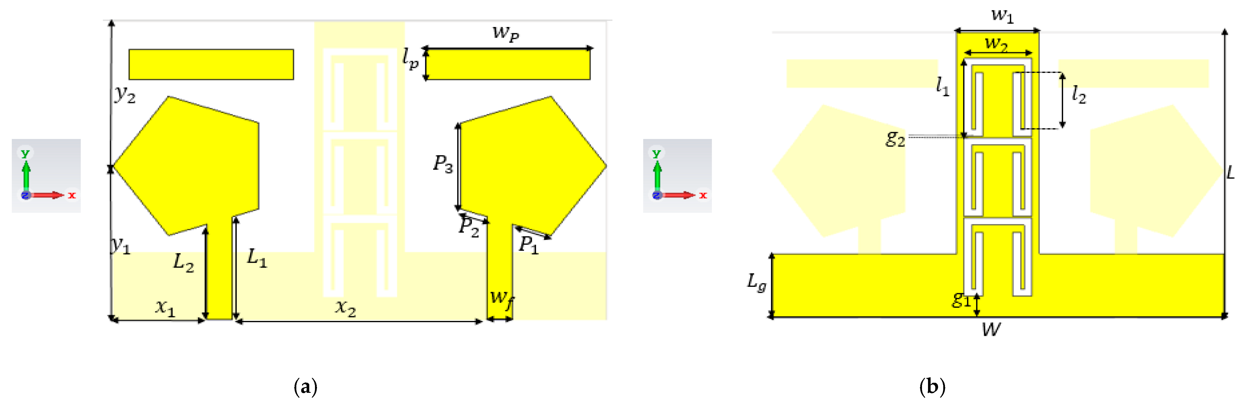
2. Antenna Design and Configuration

The printed geometry of the proposed monopole-based MIMO antenna and the design parameters are illustrated in Figure 1. The final geometrical design parameters are given in Table 1. This antenna consists of two 50 Ω microstrip-fed pentagonal radiators associated with two rectangular parasitic elements placed symmetrically on the substrate. A standard 1.6 mm thick FR4 dielectric substrate with a 4.3 relative dielectric constant and a 0.025 loss tangent is used. Three CSRR slot structures are etched into the middle of the L-shaped defective ground plane for bandwidth enhancement and coupling reduction. The proposed design has a compact overall size of 30 × 20 × 1.6 mm3.

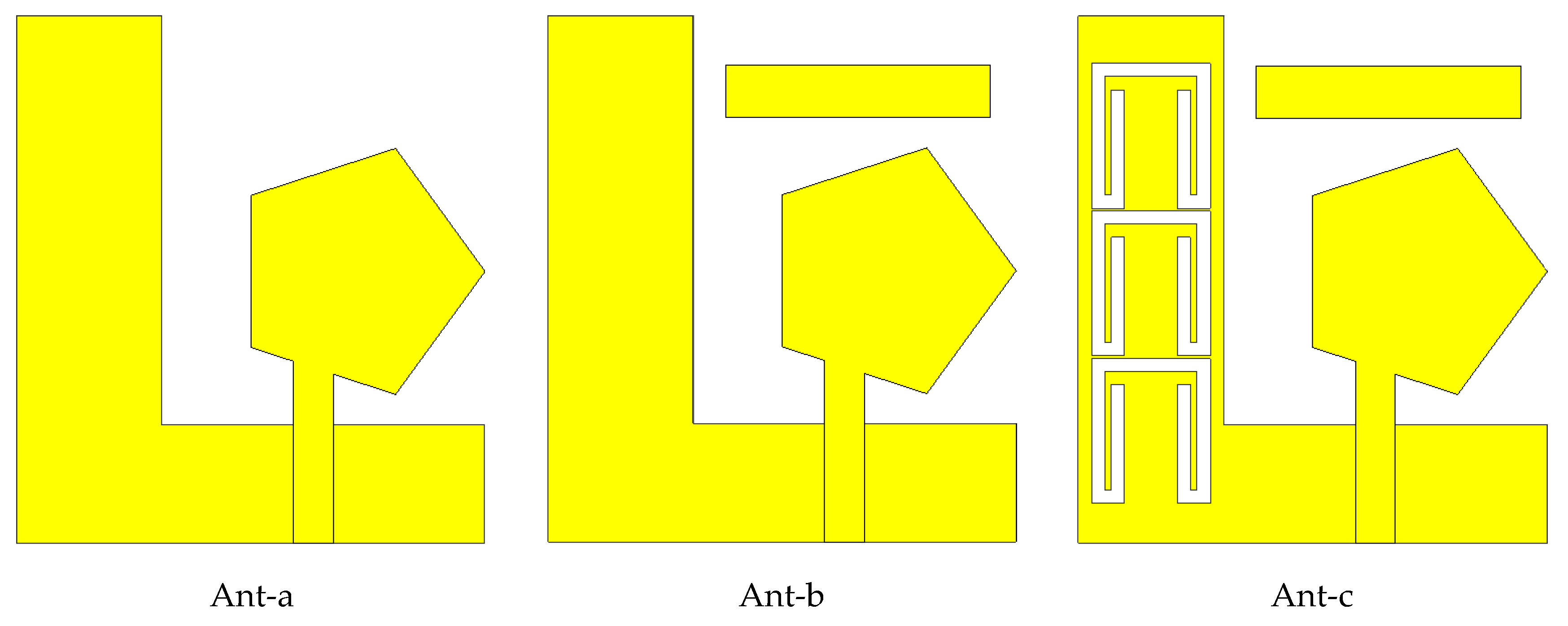
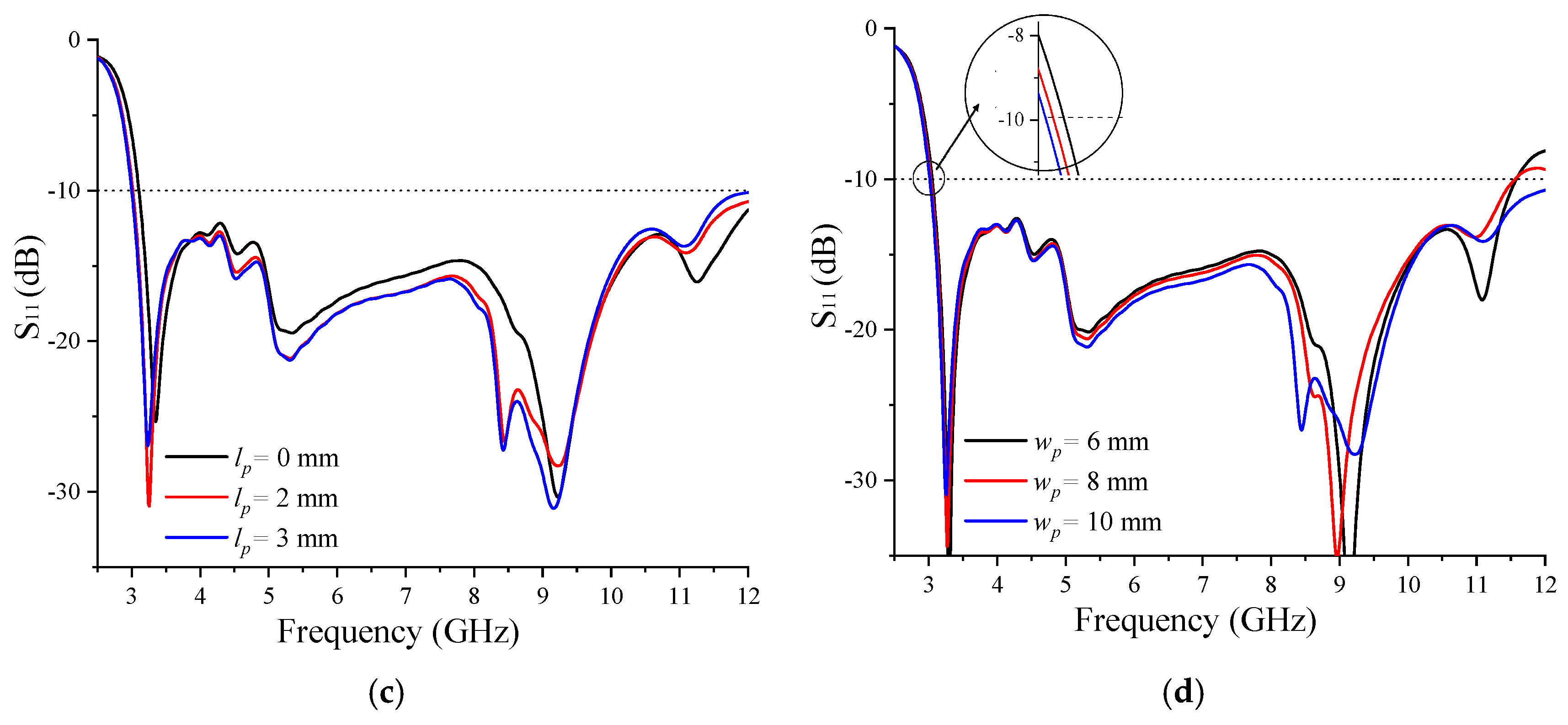
3. Design Process of the Single Element

Initially, a compact single-element monopole antenna achieving the FCC frequency band requirements was designed to form the MIMO antenna. The strategy adopted, illustrated in Figure 2, was as follows: a pentagonal patch monopole antenna was designed on a low-cost FR4 substrate with an L-shaped defective ground plane (Ant-a).
As shown in Figure 3, illustrating the reflection coefficient S11, this antenna operates in an ultra-wide frequency band under −10 dB, extending from 3.4 GHz to 11.39 GHz. To expand the lower frequency band and to improve the impedance matching, a rectangular parasitic element is added (Ant-b). According to the S11 plot in Figure 3, the lower bandwidth limit is shifted to 3.3 GHz. This slight improvement in the lower frequency band is supplemented by a more significant improvement in the impedance matching. In the last configuration, Ant-c, the ground plane is loaded by three CSRR cells. A more significant bandwidth enhancement is achieved in this case, ranging from 3.01 GHz to 12.34 GHz, covering the total FCC bandwidth allocated to UWB applications.
A parametric analysis was conducted to highlight the effects of the CSRR structure lengths (Figure 4a,b) and the parasitic-element length and width (Figure 4c,d) on the antenna bandwidth and impedance matching.
As illustrated in Figure 4a,b, the effect of the CSRR structure lengths is weak on low frequencies but is more important on high frequencies, where a wide spreading of the spectrum is observed with the increase in these lengths. It can also be observed that different resonances are created for these different lengths, which proves the effectiveness of these structures in bandwidth enhancement.
The effect of varying the dimensions of the parasitic element, as illustrated in Figure 4c,d, is manifested by a slight shifting of the frequency band for either low or high frequencies. Its effect on the impedance-mismatching improvement is also observed.

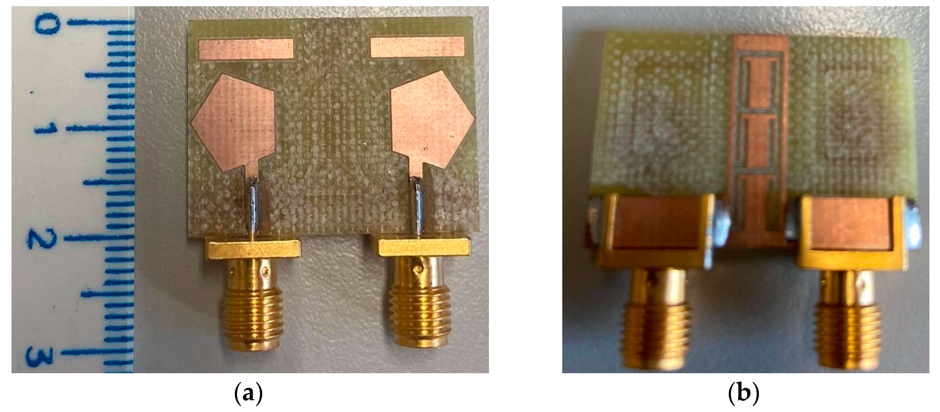
4. Design of the Proposed UWB-MIMO Antenna

The printed geometry and design parameters of the proposed monopole-based MIMO antenna are illustrated in Figure 1. The optimized geometrical design parameters are given in Table 1. This antenna consists of two 50 Ω microstrip-fed pentagonal radiators associated with two rectangular parasitic elements placed symmetrically on an FR4 dielectric substrate with a thickness (h) of1.6 mm, a relative dielectric constant (εr) of 4.3, and a loss tangent (tan δ) of 0.025. Three CSRR structures are etched into the middle of the L-shaped defective ground plane for bandwidth enhancement and coupling reduction. The proposed design has a compact overall size of 30 × 20 × 1.6 mm3.Ant-c, illustrated in Figure 2, is used to form a two-element MIMO antenna, with a compact overall size of 30 × 20 × 1.6 mm3.
To conduct the S-parameter measurements, the design prototype is connected to the PNA-X Vector Network Analyzer (VNA) device using appropriate RF/microwave cables and connectors. After calibrating the VNA, the measurement frequency range and sweep resolution are defined, and the measurement format (S11, S21, S12, S22) is selected based on the related requirements. This systematic process ensures an accurate and reliable S-parameter characterization of the RF and microwave components.
Figure 5 illustrates the simulated and measured antenna S parameters. It can be seen that the simulated reflection coefficients S11 and S22 of the two ports are identical due to the system symmetry. We ascertained the same for the coupling coefficients S12 and S21.
The reported measured values of S11 and S12 are achieved by feeding Port1 while Port2 is terminated via a matched 50-ohm load. The differences observed between the simulated and measured values are due to the introduction of SMA connectors and cables in the measurements.
It can be seen that the relative error between the S parameters associated with the two ports does not exceed 5% and 2% for theΔSii/Sii and ΔSij/Sij, respectively. The ΔSii/Sii is slightly remarkable for frequencies between 9 and 12GHz compared to those in the 2–8 GHz band, which may be attributed to measurement errors, such as the placement and soldering of the SMA port, factors that can justify this small discrepancy. The FCC bandwidth calculated for S11 under −10 dB was achieved, and the isolation between the adjacent antenna radiating elements, illustrated by the coupling coefficient S12, was greater than 22 dB in the overall frequency bandwidth. Figure 6 shows a prototype of the fabricated MIMO antenna built to the aforementioned specifications.
The surface current distribution is simulated by exciting Port1 while Port2 is terminated with a 50 Ω load. The obtained surface current distributions for 3.1 GHz, 3.5 GHz, 5 GHz, 8.5 GHz, 10 GHz, and 10.6 GHz are illustrated in Figure 7. These frequencies were chosen to highlight the radiation and isolation mechanisms. For low frequencies, the maximum current distribution is observed in the first two CSRR structures, the part of the defected ground located between the CSRRs and the radiating element, as well as the edges of the radiator located at the sides of the CSRR structures.
A weak current distribution is observed in one edge of the parasitic element, and a perfect isolation is observed for the frequency 3.5 GHz. For the frequencies 5 GHz and 8.5 GHz, it is the edges of the pentagonal patch that are in front of the partial ground that radiate, and a greater current distribution is observed for 8.5 GHz over the entire parasitic element. For higher frequencies, the radiation is obtained by the edges of the radiator located far from the CSRRs. Isolation in these cases is less important, as shown by the coupling parameter in Figure 5.
To highlight the effect of the introduction of CSRR structures in bandwidth enhancement and mutual-coupling reduction, the simulated reflection coefficients S11 and S22 and the coupling coefficients S12 and S12 are plotted for both cases (with and without the introduction of CSRR structures) in Figure 8a,b.
Indeed, in the case of the MIMO antenna without CSRR structures, the achieved frequency bandwidth spreads from 3.4 GHz to 11.39 GHz. With the introduction of the CSRR structures, the achieved frequency bandwidth spreads from 3.01 GHz to 12.34 GHz. Concerning the isolation, illustrated in Figure 8b, the introduction of the CSRR structures increased the frequency band for which the coupling coefficient was greater than 20 dB from 3.46 GHz to 2.89 GHz.
For the overall frequency bandwidth, the MIMO antenna with CSRR structures presents greater isolation than the MIMO antenna without CSRRs, except at 5 GHZ. This is confirmed by the current distributions, illustrated in Figure 9, plotted for the frequencies 3.1, 3.5, 5, and 8.5 GHz.
The setup for measuring the radiation pattern is shown in Figure 10. Figure 10a shows the block diagram of this setup, while Figure 10b shows the layout inside an anechoic chamber. In this scheme, the horn antenna acts as the transmitter, while the design under test (AUT) functions as the receiver. Both antennas are connected to the VNA, which provides the necessary power to the horn and collects power from the AUT. The resulting data are then fed to the software, which generates the corresponding radiation pattern.
The normalized two-dimensional radiation patterns of the UWB-MIMO antenna in the φ = 0   and θ = 90 °   planes are depicted in Figure 11, corresponding to the excitation of Port1 at frequencies of 3.1 GHz, 7.5 GHz, and 10.6 GHz. The observed results exhibit a strong level of agreement. The radiation pattern of the proposed antenna looks like the horizontal dipole radiation pattern, it is omnidirectional, and the φ = 0 plane corresponds to the H-plane and the θ = 90 °   plane corresponds to the E-plane. A slight inclination is observed for 7.5 GHz and 10.6 GHz.
Figure 12 depicts the simulated and measured results for the peak gain and radiation efficiency of the UWB-MIMO antenna. The peak gain exhibits a range of from −1 dBi to 6 dBi, and the efficiency ranges from 77.3% to 95.3%, within the desired FCC UWB frequency range. The simulation was carried out without introducing the SMA connector; this is the cause of the differences observed between the simulations and measurements. The introduction of this port into the manufactured prototype caused additional ohmic losses, leading to the reduction in the antenna efficiency and, consequently, its gain.

5. Investigation of the MIMO-Antenna Diversity Performance

When a single antenna is designed, one looks to some of its individual parameters, like the S11, input impedance, radiation pattern, efficiency, and gain, to measure its performance. In the case of the MIMO antenna in which several single elements are working together, other parameters are used to measure its performance, namely, the envelope correlation coefficient (ECC), the diversity gain (DG), the total active reflection coefficient (TARC),the channel capacity loss (CCL), and the mean effective gain (MEG). The calculation of these parameters is usually called the evaluation of the diversity performance of the MIMO system.

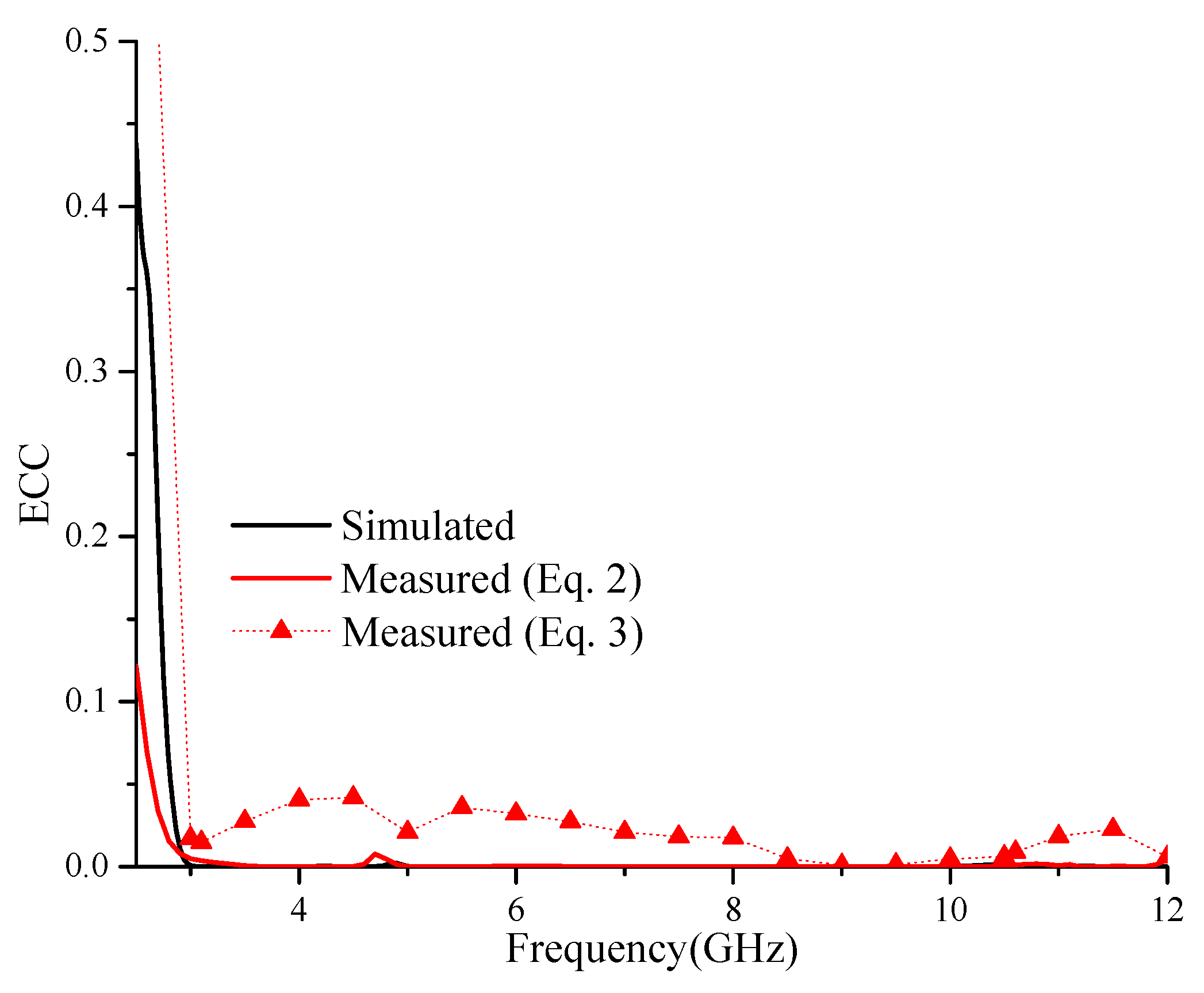
5.1. Envelope Correlation Coefficient (ECC)

The envelope correlation coefficient (ECC) is an important parameter used to measure the MIMO-antenna performance. It indicates the correlation or isolation between the branch signals received by the different MIMO-antenna elements. For a perfect inter-element isolation, the ideal value of the ECC is 0; however, in practice, a value under 0.5 is generally considered to be good enough to achieve a good diversity performance [30,33,36,37]. In the literature, three methods are proposed to evaluate the ECC. It can be calculated from the S parameters of the different antenna elements, from their radiation patterns, or from the combination of the radiation efficiency and S parameters. Calculating the ECC using the far field is more reliable but time-consuming and expensive because it is tedious in terms of the measurements and calculation [38,39,40]. Its calculation using the combination of the S parameters and radiation efficiency is complex but more reliable for higher efficiencies and gives the correct estimation for lossy antennas; however, this technique presents some limitations: it gives higher ECC values in the case of antennas presenting low radiation efficiencies and it is not suitable for tilted-beam radiation patterns [36,39]. In [40], an exact ECC expression using the S parameters is given. This expression is derived from the far-field ECC formula for the case of a two-element antenna, and the technique is easy, fast, and provides a clear understanding of the effects of mutual coupling and impedance matching on the MIMO diversity performance, but it is less reliable in the case of lossy antennas for ultra-wideband computation [36,38,39]. Equations (1)–(3) give the mathematical expressions used to calculate the ECC using the far field, the S parameters without consideration of the losses, and the combination of the S parameters and radiation efficiency, respectively, in the general case of an N-element MIMO antenna [36,38,39]:
ρ i j e = 4 π F i * θ , ϕ . F j * θ , ϕ d Ω 2 4 π F i * θ , ϕ 2 d Ω 4 π F j * θ , ϕ 2 d Ω
where F i * θ , ϕ and F j * θ , ϕ are the radiation patterns of the ith and jth radiating elements with respect to the elevation angle ( θ ) and the azimuthal angle ( ϕ ), and Ω is the solid angle;
ρ i j e = n = 1 N S n i * S n j 1 n = 1 N S n i 2 1 n = 1 N S n j 2
ρ i j e = n = 1 N S n i * S n j 1 n = 1 N S n i 2 1 n = 1 N S n j 2 η r a d , i η r a d , j + 1 η r a d , i 1 1 η r a d , j 1
where i = 1 , N and j = 1 , N are the antenna ports, and N is the number of radiating elements. S n i and S n j are the scattering parameters of the antenna elements, and S n i * is the conjugate of S n i . η r a d , i and η r a d , j are the radiation efficiencies of the ith and jth MIMO-antenna radiating elements.
The ECC in this paper is calculated using simulated and measured S parameters with and without consideration of the efficiency. The ECC value, calculated either from simulated or measured S parameters (Equation (2)), is lower than 0.01, as illustrated in Figure 13. The ECC value is also calculated from the measured S parameters and efficiency (Equation (3)). The obtained values, illustrated in Figure 13, are less than 0.05, a result which remains below the limit value of 0.5. These lower ECC values obtained over the entire FFC frequency band meet the good diversity standard for the MIMO system.

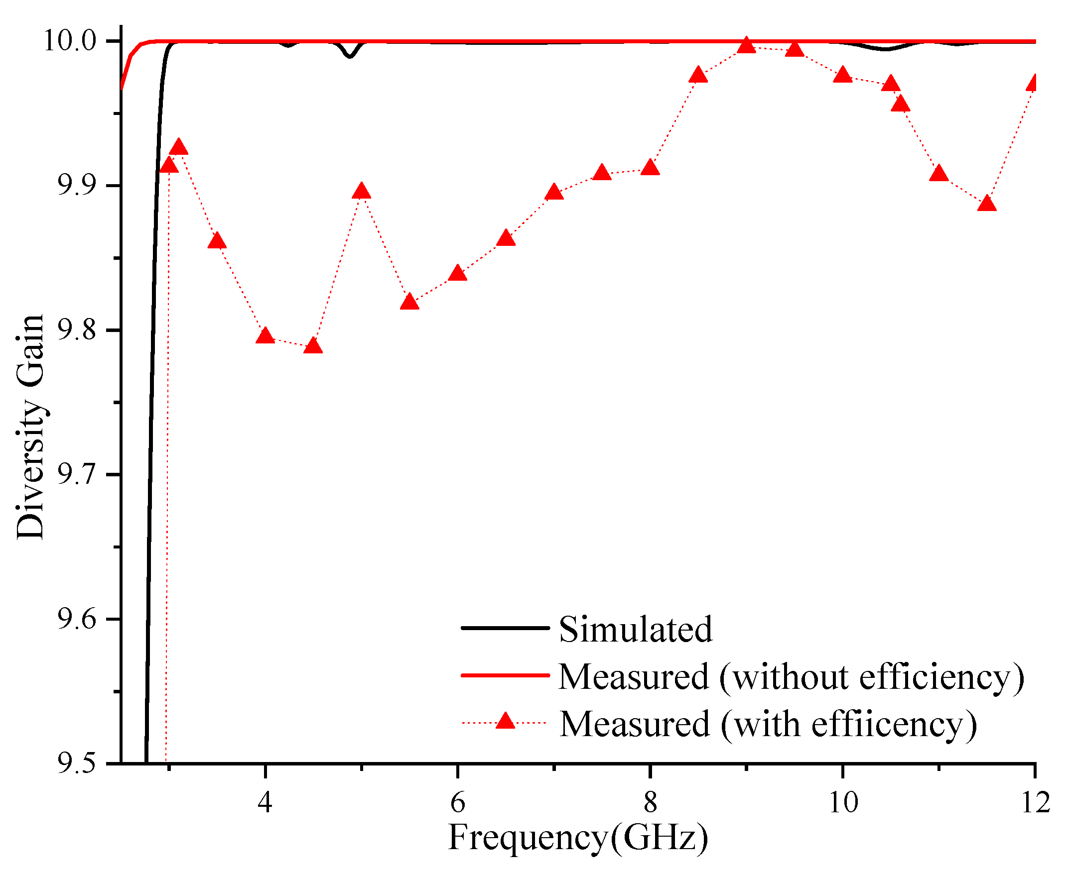
5.2. Diversity Gain (DG)

The diversity gain (DG) is used in MIMO-system gain enhancement and gives insight into the effects of the diversity on the wireless links. It is calculated using Equation (4) [41]:
D G = 10 1 E C C
It is clear from Equation (4) that the lower value of the correlation coefficient is associated with a greater diversity gain. For an ideal zero correlation coefficient corresponds an ideal constant diversity gain value of 10 [37].
In this study, the resulting simulated and measured diversity gains calculated using the S parameters stand between 9.990 and 10 in the entire frequency band, as shown in Figure 14. However, the resulting measured diversity gains calculated using the S parameters and radiation efficiency stand between 9.8 and 10 in the entire frequency band, due to the consideration of the efficiency.

5.3. Total Active Reflection Coefficient (TARC)

The TARC is another parameter used to measure the diversity. It depends on the antenna S parameters and defines the return loss in the MIMO antenna. For the case of a two-element MIMO antenna, it can be estimated using the following equation [35,41], in which an ideal value of zero is desired:
T A R C = S 11 + S 12 e j θ 2 + S 21 + S 22 e j θ 2 2
For the random excitation phase (θ), different values of the TARC are obtained. Simulated TARCs for different excitation phases (θ) taken from 0 to 180° with a step of 30° are illustrated in Figure 15.
From these curves, it is obvious that the TARCs consistently exhibit values below −12 dB in the entire FCC frequency band. Furthermore, all the curves within the family display a notable level of convergence, implying that the proposed antenna is not sensible to the phase variations. Consequently, this guarantees a substantial reduction in the mutual coupling between the different ports.

5.4. Channel Capacity Loss (CCL)

The CCL is another significant diversity performance parameter used to examine the MIMO-antenna performance. For an efficient MIMO-antenna performance, it can be defined as the rate of data reliably transmitted over a specific channel in a fading environment [8,39]. For a better performance, the CCL must be less than 0.4 bits/Hz/s [36,37]. It is calculated using the S parameters using Equations (6)–(8) [36,39,41]:
C L L = ψ R
where ψ R is the correlation matrix of the receiving antenna for the case of a two-element MIMO antenna, which is obtained as follows:
ψ R = ρ 11   ρ 12   ρ 21 ρ 22
ρ i i = 1 S i i 2 + S j i 2 ;   ρ i j = S i i * S i j S j i * S j j
Figure 16 illustrates the simulated and measured CCLs. Less than 0.25 bits/Hz/s CLL values were obtained over the entire FFC frequency span. This lower CCL meets the good diversity standard for the MIMO system.

5.5. Mean Effective Gain (MEG)

The MEG, which describes the antenna effect in the link budget, is a measure of how much better a MIMO antenna performs than an isotropic antenna. This helps to measure how well the antenna performs in a real environment. It takes into account both the antenna’s gain and the environmental factors that can affect the signal. For a better performance, this ratio must be less than 3 dB [36,37]. It can be calculated using the following two expressions [42]:
M E G 1 = 0.5   η 1 , r a d = 0.5 1 S 11 2 S 12 2
M E G 2 = 0.5   η 2 , r a d = 0.5 1 S 21 2 S 22 2
According to Figure 17, the simulated MEG remains at a constant level of 3 dB over the frequency band. This obtained result falls within the standard range expected for MIMO systems.
A performance comparison was performed between the proposed UWB-MIMO antenna and other two-element MIMO structures, and the results are reported in Table 2. Various aspects, such as the antenna size, bandwidth, isolation, gain, radiation efficiency, and diversity performance parameters namely: ECC, DG, CCL, TARC, and MEG, were considered. The proposed antenna offers several advantages, including its compact size, innovative structure, excellent isolation, good radiation efficiency, and good diversity performance parameters, compared to the designs reported in the literature.

6. Conclusions

The main goal of this study was the development of a compact multi-antenna system operating in the 3.1–10.6 GHz frequency band and covering a wide range of wireless applications and satellite communications. The proposed designed antenna exhibits an ultra-wide frequency band, a high level of isolation, and a good diversity performance. To meet the FCC UWB requirements, two rectangular parasitic elements are incorporated into the radiating structure. Additionally, the isolation is enhanced through the utilization of metamaterial CSRR structures etched into the L-shaped defected ground plane, and an important low-frequency shifting is achieved. The fabricated antenna prototype exhibits performances that closely align with the simulation predictions. The designed antenna presents an ultra-wide frequency band spreading from 3.01 to 12.3 GHz, quite high mutual coupling (exceeding 22 dB), a quasi-omnidirectional radiation pattern, and good diversity parameters, including the EDG, ECC, TARC, CCL, and ratio of MEGs. These results collectively meet the UWB-MIMO system requirements.

Author Contributions

Conceptualization, Y.T., C.B., R.Z., P.S. and D.S.; methodology, Y.T., C.B., I.E. and S.M.; software, Y.T., C.B., M.L.B. and C.Z.; validation, I.E., R.Z. and P.S.; formal analysis, M.L.B. and R.Z.; investigation, I.E. and J.R.; writing—original draft preparation, Y.T., C.B. and S.M.; writing—review and editing, R.Z., D.S. and P.S.; visualization, S.M.; supervision, I.E. and R.Z.; project administration, I.E.; funding acquisition, I.E. and P.S. All authors have read and agreed to the published version of the manuscript.

Funding

This project received funding, in part, from the DGRSDT (Direction Générale de la Recherche Scientifique et du Développement Technologique), MESRS (Ministry of Higher Education and Scientific Research), Algeria and in part, by the National Research Foundation of Korea (NRF) grant funded by the Korean government (NRF-2022R1G1A1004799).

Data Availability Statement

The data presented in this study are available in the article.

Conflicts of Interest

The authors declare no conflict of interest.

References

  1. Che, F.; Ahmed, Q.Z.; Lazaridis, P.I.; Sureephong, P.; Alade, T. Indoor Positioning System (IPS) Using Ultra-Wide Bandwidth (UWB)—For Industrial Internet of Things (IIoT). Sensors 2023, 23, 5710. [Google Scholar] [CrossRef]
  2. Gupta, M.; Kumar, A.; Aggarwal, B.; Cengiz, K.; Singh, G. 5G Wireless Communication System in Healthcare Informatics; CRC Press: Boca Raton, FL, USA, 2023; ISBN 9781032312194. [Google Scholar]
  3. Zhang, R.; Liang, Y.C.; Hall PS, P.; Gardner, P.; Kelly, J.; Ebrahimi, E. Federal Communications Commission revision of Part 15 of the commission’s rules regarding ultra-wideband transmission systems. FCC Wash. DC First Rep. Order 2009, 48, 133–135. [Google Scholar]
  4. Youssef, A.A. Adaptive LDPC Coded High Data Rate Based IR-UWB Combined with VMIMO System for Vehicular Communication Links. AEU-Int. J. Electron. Commun. 2023, 169, 154747. [Google Scholar] [CrossRef]
  5. Gvozdarev, A.S.; Alishchuk, A.M.; Kazakova, M.A. Closed-Form Capacity Reliability Analysis of Multiuser MIMO System in the Presence of Generalized Multipath Fading. Sensors 2023, 23, 2289. [Google Scholar] [CrossRef]
  6. Sohi, A.K.; Kaur, A. Slot and SRR-Loaded Quad-Port, Hen-Shaped Fractal UWB-MIMO Antenna with Quad Band-Reject Ability for Handheld 4G/5G Wireless Devices. Iran. J. Sci. Technol. Trans. Electr. Eng. 2023, 47, 1187–1205. [Google Scholar] [CrossRef]
  7. Gurjar, R.; Upadhyay, D.K.; Kanaujia, B.K.; Sharma, K. A Novel Compact Self-Similar Fractal UWB-MIMO Antenna. Int. J. RF Microw. Comput.-Aided Eng. 2019, 29, e21632. [Google Scholar] [CrossRef]
  8. Altaf, A.; Iqbal, A.; Smida, A.; Smida, J.; Althuwayb, A.A.; Hassan Kiani, S.; Alibakhshikenari, M.; Falcone, F.; Limiti, E. Isolation Improvement in UWB-MIMO Antenna System Using Slotted Stub. Electronics 2020, 9, 1582. [Google Scholar] [CrossRef]
  9. Kulkarni, J.; Alharbi, A.G.; Sim, C.-Y.-D.; Elfergani, I.; Anguera, J.; Zebiri, C.; Rodriguez, J. Dual Polarized, Multiband Four-Port Decagon Shaped Flexible MIMO Antenna for Next Generation Wireless Applications. IEEE Access 2022, 10, 128132–128150. [Google Scholar] [CrossRef]
  10. Patel, A.; Desai, A.; Elfergani, I.; Vala, A.; Mewada, H.; Mahant, K.; Patel, S.; Zebiri, C.; Rodriguez, J.; Ali, E. UWB CPW Fed 4-Port Connected Ground MIMO Antenna for Sub-Millimeter-Wave 5G Applications. Alex. Eng. J. 2022, 61, 6645–6658. [Google Scholar] [CrossRef]
  11. Kaur, H.; Singh, H.S.; Upadhyay, R. Design and Analysis of Compact Quad-Element MIMO Antenna with Asymmetrical Ground Structures for Ultra-Wideband Communication. Wirel. PersCommun 2022, 124, 3105–3127. [Google Scholar] [CrossRef]
  12. Sheriff, N.; Kamal Abdul Rahim, S.; Tariq Chattha, H.; Kim Geok, T. Multiport Single Element Mimo Antenna Systems: A Review. Sensors 2023, 23, 747. [Google Scholar] [CrossRef]
  13. Biswas, A.K.; Chakraborty, U. Reduced Mutual Coupling of Compact MIMO Antenna Designed for WLAN and WiMAX Applications. Int. J. RF Microw. Comput. Aided Eng. 2019, 29, e21629. [Google Scholar] [CrossRef]
  14. Addepalli, T.; Anitha, V.R. Design and Analysis of a Novel Compact Spanner-Shaped Ultra-Wideband Antenna for MIMO Systems. Int. J. Commun. Syst. 2021, 34, e4739. [Google Scholar] [CrossRef]
  15. Amroun, A.; Zebiri, C.; Sayad, D.; Elfergani, I.T.E.; Desai, A.; Bouknia, M.L.; Zegadi, R.; Rodriguez, J. Miniaturized Six-Ring Elliptical Monopole-Based MIMO Antenna for Ultrawideband Applications. Int. J. Commun. Syst. 2023, 36, e5557. [Google Scholar] [CrossRef]
  16. Kumar, A.; Ansari, A.Q.; Kanaujia, B.K.; Kishor, J.; Matekovits, L. A review on different techniques of mutual coupling reduction between elements of any MIMO antenna. Part 1: DGSs and parasitic structures. Radio Sci. 2021, 56, e2020RS007122. [Google Scholar] [CrossRef]
  17. Kumar, P.; Pathan, S.; Vincent, S.; Kumar, O.P.; Yashwanth, N.; Kumar, P.; Shetty, P.R.; Ali, T. A Compact Quad-Port UWB-MIMO Antenna with Improved Isolation Using a Novel Mesh-like Decoupling Structure and Unique DGS. IEEE Trans. Circuits Syst. II Express Briefs 2023, 70, 949–953. [Google Scholar] [CrossRef]
  18. Abbas, M.A.; Allam, A.; Gaafar, A.; Elhennawy, H.M.; Sree, M.F.A. Compact UWB-MIMO Antenna for 5G Millimeter-Wave Applications. Sensors 2023, 23, 2702. [Google Scholar] [CrossRef]
  19. Patel, A.; Vala, A.; Desai, A.; Elfergani, I.; Mewada, H.; Mahant, K.; Zebiri, C.; Chauhan, D.; Rodriguez, J. Inverted-L Shaped Wideband MIMO Antenna for Millimeter-Wave 5G Applications. Electronics 2022, 11, 1387. [Google Scholar] [CrossRef]
  20. Desai, A.; Palandoken, M.; Elfergani, I.; Akdag, I.; Zebiri, C.; Bastos, J.; Rodriguez, J.; Abd Alhameed, R.A. Transparent 2-Element 5G MIMO Antenna for Sub-6 GHz Applications. Electronics 2022, 11, 251. [Google Scholar] [CrossRef]
  21. Das, P.; Singh, A.K.; Mandal, K. Metamaterial Loaded Highly Isolated Tunable Polarisation Diversity MIMO Antennas for THz Applications. Opt. Quant. Electron. 2022, 54, 250. [Google Scholar] [CrossRef]
  22. Gayatri, T.; Srinivasu, G.; Chaitanya, D.M.K.K.; Sharma, V.K. High Isolation Four-Port Wrench Shaped Compact UWB-MIMO Antenna for 3.1–10.6 GHz Band. PIER C 2022, 122, 67–82. [Google Scholar] [CrossRef]
  23. Babu, N.S.; Ansari, A.Q.; Kanaujia, B.K.; Singh, G.; Kumar, S. A Two-Port UWB-MIMO Antenna with an EBG Structure for WLAN/ISM Applications. Mater. Today Proc. 2023, 74, 334–339. [Google Scholar] [CrossRef]
  24. Sanmugasundaram, R.; Natarajan, S.; Rajkumar, R. A compact MIMO antenna with electromagnetic bandgap structure for isolation enhancement. Prog. Electromagn. Res. C 2021, 107, 233–244. [Google Scholar] [CrossRef]
  25. Fritz-Andrade, E.; Jardon-Aguilar, H.; Tirado-Mendez, J.A. Mutual Coupling Reduction of Two 2x1 Triangular-Patch Antenna Array Using a Single Neutralization Line for MIMO Applications. Radioengineering 2018, 27, 976–982. [Google Scholar] [CrossRef]
  26. Banerjee, J.; Gorai, A.; Ghatak, R. A Novel Isolation Improvement Technique Using Fractal Neutralization Line with Dual Band Rejection Attributes in a Compact UWB-MIMO Antenna. Int. J. Microw. Wirel. Technol. 2022, 15, 1–12. [Google Scholar] [CrossRef]
  27. Kumar, P.; Ali, T.; Mm, M.P. Characteristic Mode Analysis-Based Compact Dual Band-Notched UWB-MIMO Antenna Loaded with Neutralization Line. Micromachines 2022, 13, 1599. [Google Scholar] [CrossRef]
  28. Dkiouak, A.; El Ouahabi, M.; Chakkor, S.; Baghouri, M.; Zakriti, A.; Lagmich, Y. High Performance UWB-MIMO Antenna by Using Neutralization Line Technique. Prog. Electromagn. Res. C 2023, 131, 185–195. [Google Scholar] [CrossRef]
  29. Li, Y.; Bian, L.; Xu, K.; Liu, Y.; Wang, Y.; Chen, R.; Xie, S. Mutual Coupling Reduction for Monopole MIMO Antenna Using L-Shaped Stubs, Defective Ground and Chip Resistors. AEU-Int. J. Electron. Commun. 2023, 160, 154524. [Google Scholar] [CrossRef]
  30. Iqbal, A.; Saraereh, O.A.; Ahmad, A.W.; Bashir, S. Mutual coupling reduction using F-shaped stubs in UWB-MIMO antenna. IEEE Access 2017, 6, 2755–2759. [Google Scholar] [CrossRef]
  31. Li, Z.; Du, Z.; Takahashi, M.; Saito, K.; Ito, K. Reducing mutual coupling of MIMO antennas with parasitic elements for mobile terminals. IEEE Trans. Antennas Propag. 2011, 60, 473–481. [Google Scholar] [CrossRef]
  32. Revati, C.G.; Patil, R.R. Slot-based mutual coupling reduction technique for MIMO antenna. SN Comput. Sci. 2021, 2, 104. [Google Scholar] [CrossRef]
  33. You, X.; Du, C.; Yang, Z.P. A Flexible CPW 2-Port Dual Notched-Band UWB-MIMO Antenna for Wearable IoT Applications. Prog. Electromagn. Res. C 2023, 128, 155–168. [Google Scholar] [CrossRef]
  34. Asadpor, L.; Rezvani, M. Multiband microstrip MIMO antenna with CSRR loaded for GSM and LTE applications. Microw. Opt. Technol. Lett. 2018, 60, 3076–3080. [Google Scholar] [CrossRef]
  35. Tirado-Mendez, J.A.; Jardon-Aguilar, H.; Flores-Leal, R.; Rangel-Merino, A.; Vasquez-Toledo, L.A.; Rodriguez-Colina, E.; Marcelin-Jimenez, R.; Pascoe-Chalke, M. Metamaterial Split-Ring Resonators Applied as Reduced-Size Four-Port Antenna Array for MIMO Applications. AEU-Int. J. Electron. Commun. 2022, 154, 154338. [Google Scholar] [CrossRef]
  36. Kumar, A.; Ansari, A.Q.; Kanaujia, B.K.; Kishor, J.; Matekovits, L. A review on different techniques of mutual coupling reduction between elements of any MIMO antenna. Part 2: Metamaterials and many more. Radio Sci. 2021, 56, e2020RS007222. [Google Scholar] [CrossRef]
  37. Islam, H.; Das, S.; Ali, T.; Bose, T.; Dhar, S.; Rai, B.; Kumar, P. Compact circularly polarized 2 and 4 port multiple input multiple output antennas with band stop filter isolation technique. Alex. Eng. J. 2023, 66, 357–376. [Google Scholar] [CrossRef]
  38. Nadeem, I.; Choi, D.Y. Study on mutual coupling reduction technique for MIMO antennas. IEEE Access 2018, 7, 563–586. [Google Scholar] [CrossRef]
  39. Al-saedi AJ, H.; Perez, J.C. A Review: Compact size and isolation of MIMO antenna. PrzeglądElektrotechniczny 2022, 11–17. [Google Scholar] [CrossRef]
  40. Blanch, S.; Romeu, J.; Corbella, I. Exact Representation of Antenna System Diversity Performance from Input Parameter Description. Electron. Lett. 2003, 39, 705–707. [Google Scholar] [CrossRef]
  41. Govindan, T.; Palaniswamy, S.K.; Kanagasabai, M.; Kumar, S. Design and Analysis of UWB-MIMO Antenna for Smart Fabric Communications. Int. J. Antennas Propag. 2022, 2022, e5307430. [Google Scholar] [CrossRef]
  42. Alsharari, M.; Lavadiya, S.; Aliqab, K.; Armghan, A.; Daher, M.G.; Patel, S.K. A Novel Design of Complementary Split Ring Resonator Metamaterial-Based Low-Profile MIMO Antenna with Defected Ground Structure for S/C/X/Ka Band Applications. Micromachines 2023, 14, 1232. [Google Scholar] [CrossRef] [PubMed]
  43. Kiani, S.H.; Savci, H.S.; Munir, M.E.; Sedik, A.; Mostafa, H. An Ultra-Wide Band MIMO Antenna System with Enhanced Isolation for Microwave Imaging Applications. Micromachines 2023, 14, 1732. [Google Scholar] [CrossRef] [PubMed]
Figure 1. Proposed UWB-MIMO antenna: (a) top layout, and (b) bottom layout.
Electronics 12 04852 g001
Figure 2. Design steps of single-element antenna.
Electronics 12 04852 g002
Figure 3. Simulated reflection coefficient S11 of the three antenna structures.
Electronics 12 04852 g003
Figure 4. Effects of different values of CSRR on antenna bandwidth and impedance matching: (a) length l 1 ; (b) length l 2 and parasitic element; (c) length l p ; and (d) width w p .
Electronics 12 04852 g004aElectronics 12 04852 g004b
Figure 5. Simulated and measured results of S parameters: (a) S11 and S22, and (b) S12 and S21.
Electronics 12 04852 g005
Figure 6. Fabricated prototype of the proposed UWB-MIMO antenna: (a) top layout, and (b) bottom layout.
Electronics 12 04852 g006
Figure 7. Surface current distributions in different parts of the MIMO antenna for f = 3.1   G H z , f = 3.5   G H z , f = 5   G H z , f = 8.5   G H z , f = 10   G H z , and f = 10.6   G H z .
Electronics 12 04852 g007aElectronics 12 04852 g007b
Figure 8. Simulated results of S parameters of the proposed antenna with and without CSRR structures: (a) reflection coefficients S11/S22; (b) coupling coefficients S12/S21.
Electronics 12 04852 g008
Figure 9. Surface current distributions in different parts of the MIMO antenna without CSRR structures for f = 3.1   G H z , f = 3.5   G H z , f = 5   G H z , and f = 8.5   G H z .
Electronics 12 04852 g009
Figure 10. Radiation pattern measurement setup: (a) block diagram, and (b) layout inside anechoic chamber.
Electronics 12 04852 g010
Figure 11. Radiation patterns of the proposed UWB-MIMO antenna at (a) 3.1 GHz, (b) 7.5 GHz, and (c) 10.6 GHz.
Electronics 12 04852 g011
Figure 12. Simulated and measured peak gains and radiation efficiencies of the proposed MIMO antenna.
Electronics 12 04852 g012
Figure 13. Measured and simulated ECCs of proposed MIMO antenna.
Electronics 12 04852 g013
Figure 14. Simulated and measured diversity gains of proposed antenna.
Electronics 12 04852 g014
Figure 15. Total active reflection coefficients of proposed antenna.
Electronics 12 04852 g015
Figure 16. Simulated and measured channel capacity losses of proposed antenna.
Electronics 12 04852 g016
Figure 17. Simulated MEGs of proposed antenna.
Electronics 12 04852 g017
Table 1. Optimized parameters of the proposed UWB-MIMO antenna.
ParameterValue (mm)ParameterValue (mm)
L 20 y 2 9.7
W 30 w f 1.5
l g 4.78 l p 2
L 1 6.9 w p 10
L 2 6.41 l 1 5.5
P 1 2.49 l 2 4.5
P 2 1.7 w 1 5.5
P 3 5.76 w 2 4.5
x 1 5.75 g 1 2.25
x 2 15.5 g 2 0.1
y 1 10.3 d x 12.25
Table 2. Performance comparison with reported two-element MIMO antennas.
YearRef.Size
(mm2)
Bandwidth (GHz)No. of PortsIsolation (dB)Gain
(dBi)
Efficiency
(%)
ECCDG (dB)CCL (bits/Hz/s)TARC (dB)MEG (dB)
2019[8]24 × 323.1–12.52≥164.8NG≤0.05≥9.90.4NG≤−3
2019[13]55 × 282.01–3.92≥152NG≤0.01>9.80.2<0<−3
2020[9]33 × 482–13.72≥204.396≤0.15>9.850.06NGNG
2021[24]27.9 × 381.5–3.52≥20NGNG<0.2NGNGNGNG
2022[20]70 × 254.65–4.972≥151.6545<0.03>9.80.15>−121
2022[33]29.5 × 603–202≥23NG98<0.001>9.9950.3NGNG
2023[23]30 × 603–122≥25590NGNGNGNGNG
2023[28]46 × 463.1–11.72≥16.5NG55<0.057>9.78≤0.25≤−10NG
2023[37]29.5 × 603–15.72≥206.2NG<0.045>9.9980.3NGNG
2023[43]52 × 262.3–11.52≥165.998<0.01210NGNGNG
Proposed antenna30 × 203.01–12.342≥225.570<0.0025100.15<−12−3
Disclaimer/Publisher’s Note: The statements, opinions and data contained in all publications are solely those of the individual author(s) and contributor(s) and not of MDPI and/or the editor(s). MDPI and/or the editor(s) disclaim responsibility for any injury to people or property resulting from any ideas, methods, instructions or products referred to in the content.

