Article

Dynamic Dead-Time Compensation Method Based on Switching Characteristics of the MOSFET for PMSM Drive System

1
School of Aeronautics and Astronautics, University of Electronic Science and Technology of China, Chengdu 611731, China
2
Beijing Research and Development Center, Shanghai Gatek Automotive Electronics Co., Ltd., Beijing 100176, China
*
Author to whom correspondence should be addressed.
Electronics 2023, 12(23), 4855; https://doi.org/10.3390/electronics12234855
Submission received: 1 November 2023 / Revised: 28 November 2023 / Accepted: 29 November 2023 / Published: 30 November 2023

Abstract

:
In order to effectively avoid the shoot-through issue of the semiconductor device (such as the power metal-oxide-semiconductor field-effect transistor (MOSFET)) adopted in the phase leg of the motor drives, a dead-time zone should be inserted. However, the nonlinearity caused by the dead-time effect will bring about voltage/current distortion, as well as high-order harmonics, which largely degrades the performance of motor drives, especially in low-speed operations with slight loads. In this paper, a dead-time compensation method is proposed to suppress such side effects caused by dead-time zones and improve the performance of motor drives. Compared with other existing methods, the proposed method is mainly focused on the switching characteristics of the power MOSFET, which is directly relative to the compensation time in each pulse-width modulation (PWM) period. Firstly, a detailed derivation process is elaborated to reveal the relationship between compensation time and the switching performance of the MOSFET. Meanwhile, the switching process of the MOSFET is also well analyzed, which summarizes the variations in the switching time of the MOSFET with a varied load current. Then, the multipulse test (MPT) is carried out to obtain accurate values of the switching time with the varied load current in a wide range (0–80 A) and form a 2D lookup table. As a result, the compensation method can easily be realized by combining the lookup table and linear interpolation based on the phase current of the motor dynamically. Finally, the effectiveness of the proposed method is verified based on a 12 V permanent magnet synchronous machine (PMSM) drive system. According to the relative experiment results, it can be clearly observed that the time-domain waveform distortion, high-order harmonics, and total harmonic distortion (THD) value are reduced significantly with the proposed dynamic compensation method.

1. Introduction

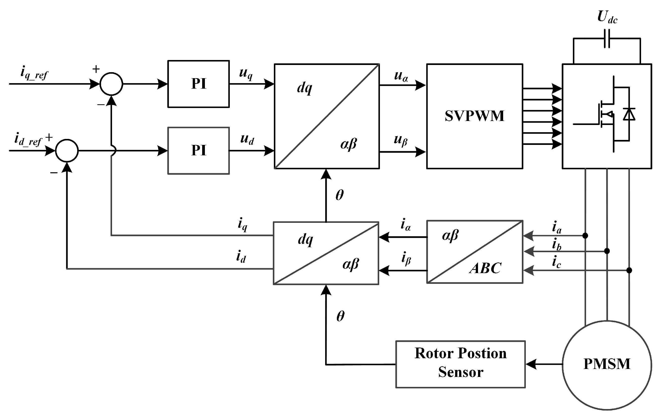
The permanent magnet synchronous motor (PMSM) has become one of the most popular choices in industry applications due to its superiority in efficiency, noise, and vibration [1,2,3,4,5,6,7]. Figure 1 shows a typical PMSM drive system based on power metal-oxide-semiconductor field-effect transistor (MOSFET), in which S A H , S A L , S B H , S B L , S C H , and S C L represent the power MOSFETs of the inverter. It is noted that the field-oriented control (FOC) algorithm combined with the space vector pulse-width modulation (SVPWM) strategy has been adopted in most cases [8,9,10,11,12]. Figure 2 shows the scheme of FOC combined with SVPWM in PMSM drives. During the control process, the voltage vector for the motor drive is synthesized by turning on or off the MOSFETs periodically. In order to avoid the shoot-through of the MOSFETs in the same phase leg, the dead-time zone should be inserted into the gate control signals of the semiconductor devices [13,14]. However, the dead-time effect will cause current distortion, as well as high-order harmonics due to its nonlinearity [15,16,17,18,19]. Especially, when the motor operates at a low rotation speed with a slight load, the harmonics will generate obvious torque ripples, which largely degrades the control performance of the motor drives [20,21]. Obviously, in order to improve the control performance of the motor drives, the nonlinearity caused by the dead-time effect requires special attention [20,22].
In recent years, there has been much research dedicated to dead-time effect suppression, and some compensation methods have been reported. In general, these compensation methods can be classified into two categories: one is based on control algorithms, which aim to force the high-orders current harmonics approximates to zero [21,22,23]; the other one is focused on the switching characteristics of the semiconductor device (such as IGBT and MOSFET), which compensates the dead time ( T d ) dynamically according to the voltage slew rate ( d v / d t ) during the switching transition of the device [24,25,26,27,28].
According to the analysis elaborated in [29], the inserted T d brings out voltage deviation between the output voltage and voltage command calculated with the FOC, which ultimately leads to current distortion, high-order harmonics, and torque ripples. As a result, it is feasible to find the voltage deviation and compensate it with the output voltage to alleviate the impact of the dead-time effect. In [30], a well-designed control algorithm is carried out by controlling the extracted sixth-order current harmonics on the d-axis approaching zero through sixth-order sinusoidal voltage injection on the d and q axes. A similar method reported in [31] is implemented by regulating the extracted fifth- and seventh-order harmonics of the three-phase current of the motor. However, it should be noted that extraction of the high-order harmonics with sufficient accuracy seems rather complicated because it contains various digital filter designs. In [29], the traditional PI controller for a current loop has been replaced by a revised repetitive controller (RRC). Compared with the method mentioned in [30,31], the RRC can reduce the sixth-order harmonics effectively without extracting accurate high-order current harmonics. In [32], an adaptive compensation method based on predictive current control is reported, which compensates the predictive reference voltage with the dead-time voltage deviation. But the accuracy of this method will be reduced once the motor parameters (such as d–q axis inductance) for voltage prediction are considered constant.
On the other hand, it should be noted that the high-order current harmonics and torque ripples originate from the inserted T d in the control signal. Obviously, it is feasible to figure out a suitable compensation time ( T c o m ) and enact it on the control signal directly to suppress the dead-time effect. In [24], the authors propose an online identification method of the compensation time ( T c o m ) according to the estimated q-axis disturbance voltage through a disturbance observer. However, the calculation process of the q-axis disturbance voltage is complicated, and it requires a high-performance microcontroller unit (MCU). In order to simplify the calculation process, the T c o m has been determined according to the switching characteristics of the IGBT in [24,25,26]. The turn-off transition time ( t o f f ) of the IGBT has been measured with the varied load current, and the turn-on transition time ( t o n ) can be assumed as zero for simplification because the load current in this case ranges only from 0 to 1.5 A. However, the t o n cannot be considered zero anymore with the increased load current. According to the switching process of the semiconductor device, the t o n will be prolonged with the increased load current [33,34]. In [27], the authors assumed that the turn-off transition of the IGBT is the charging process of the parasitic junction capacitor ( C c e ). Then, the T c o m can be acquired based on the relationships derived in [27]. However, this assumption is validated only when the device operates in quasi-zero-current-switching (QZCS) mode. Once the device operates out of the QZCS mode, the turn-off process cannot be considered as charging the C c e . According to the switching process of the IGBT and MOSFET, the QZCS turn-off usually occurs in the condition with lower load current (no more than 1 A) [35]. In [28], the snubber capacitor ( C s ) has been paralleled between the drain and source of the power MOSFET. Since the value of the junction capacitor ( C d s ) of the MOSFET is far less than that of the added C s , the turn-off process can be approximated as the charging of the C s . As a result, the T c o m can be easily obtained based on the principles discussed in [27]. However, the power loss on C s will reduce the efficiency of the motor drive, especially in large current (several tens amps) conditions.
In this paper, a dynamic dead-time compensation method based on switching characteristics of the power MOSFET is proposed for a PMSM drive system. According to relative experiment results, it can be observed that the total harmonic distortion (THD) of the phase current, as well as the high-order current harmonics, has been reduced significantly. Compared with other existing works, the main contributions of this work are summarized as follows:
  • The influence of the dead-time effect on motor drives is analyzed in detail, which manifests that the voltage deviation between voltage command and output voltage is the origin of the dead-time effect. As a result, the compensation principle can be established.
  • The switching process of the power MOSFET is analyzed, especially the normal turn-off process and the QZCS turn-off process, which demonstrates that the switching time of the MOSFET varies with the load current and cannot be considered constant. In addition, the multipulse test (MPT) and the switching time of the MOSFET can be obtained accordingly. With the MPT result, the dynamic compensation method can be realized based on the lookup table and linear interpolation.
The rest of this paper is organized as follows. In Section 2, the impact of the dead-time effect on motor drives is analyzed in detail. The switching process of the power MOSFET is elaborated in Section 3. The MPT test is implemented in Section 4 to evaluate the switching characteristics of the MOSFET. Experiment verification is carried out in Section 5 to validate the proposed compensation method. Finally, the conclusion is summarized in Section 6.

2. Impact of the Dead-Time Effect on Motor Drives

2.1. Ideal Condition (without Consideration of T d )

Figure 3 shows the voltage between phase node “a” and ground “g” ( V a g ) in ideal conditions. The A + and A represent the control signals of the S A H and S A L without consideration of the T d . The T s stands for half of the switching period of the power inverter. In this condition, V a g can be expressed as
V a g = V d c S A H = 1 & S A L = 0 V d c S A H = 0 & S A L = 1
where V d c is the dc voltage supply. According to the voltage and second principle, the V a g can be considered as
V a g = V d c · T a 2 T s
in which, T a is the “ON” state time of S A H ( T a = T 2 T 1 ). Similarly, it can be obtained as follows:
V b g = V d c · T b 2 T s V c g = V d c · T c 2 T s
in which V b g and V c g are the voltage between phase nodes (point “b” and point “c”) and the ground (point “g”), and T b and T c are the “ON” state time of S B H and S C H . Since the summation of the three-phase voltage of the motor drive ( V a s , V b s , V c s ) can be assumed tp be zero, the following relationship can be acquired:
V a s = V d c 3 · 2 T a T b T c 2 T s V b s = V d c 3 · 2 T b T a T c 2 T s V c s = V d c 3 · 2 T c T a T b 2 T s

2.2. Actual Condition (with Consideration of T d )

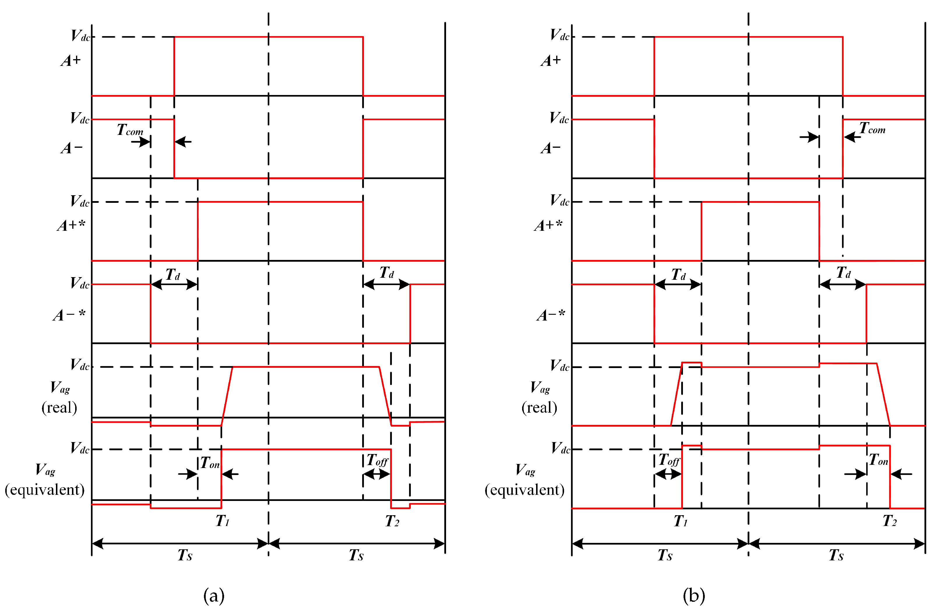
Figure 4 illustrates the voltage between phase node “a” and ground “g” ( V a g ) with the consideration of T d . Different from the ideal condition, the T d is inserted into the actual control signals A + * and A * .
According to Figure 4a ( i a s ≥ 0), S A H is turned on and S A L is turned off in state “10”. The V a g in this case is considered as the deviation between V d c and the on-state voltage of the S A H . In state “00”, both S A H and S A L are turned off. In this case, the load current flows through the body diode of S A L . Thus, V a g can be viewed as the voltage drop on the body diode of S A L . In state “01”, S A H is off and S A L is on. The V a g can be considered as the on-state voltage of the S A L . Therefore, the V a g in a complete switching period can be expressed as
V a g = V d c R d s · i a s S A H = 1 & S A L = 0 ( V d o + R d · i a s ) S A H = 0 & S A L = 0 R d s · i a s S A H = 0 & S A L = 1
where R d s and R d are the on-state resistance of the MOSFET and its body diode, V d o is the forward voltage of the body diode, and i a s is the phase A current of the motor.
According to Figure 4b ( i a s ≤ 0), S A H is turned on and S A L is turned off in state “10”. The V a g in this situation can be considered as the summation of V d c and the on-state voltage of the S A H . In state “00”, both S A H and S A L are turned off. In this case, the load current flows through the body diode of S A H . Thus, V a g can be viewed as the summation of V d c and voltage drop on the body diode of S A H . In state “01”, S A H is off and S A L is on. The V a g can be viewed as the on-state voltage of the S A L . Therefore, the V a g in a complete switching period can be expressed as
V a g = V d c + R d s · i a s S A H = 1 & S A L = 0 V d c + ( V d o + R d s · i a s ) S A H = 0 & S A L = 0 R d s · i a s S A H = 0 & S A L = 1

2.3. Impact of the Dead-Time Effect

According to Figure 4a ( i a s > 0), the V a g can be derived as the following type based on voltage and second principle:
V a g = V d c · T a + T c o m T d T o n + T o f f 2 T s V d o · 2 T a + T o n T o f f 2 T s R d s ( R d s R d ) · 2 T d + T o n T o f f 2 T s · i a s
where T c o m represents the compensation time added on the control signals. According to Figure 4b ( i a s < 0), (7) should be modified as
V a g = V d c · T a T c o m T d T o n + T o f f 2 T s + V d o · 2 T d + T o n T o f f 2 T s R d s ( R d s R d ) · 2 T d + T o n T o f f 2 T s · i a s
Therefore, the V a g can be expressed as the following type, whether i a s > 0 or i a s < 0:
V a g = V d c · T a + s i g n ( i a s ) T c o m T d T o n + T o f f 2 T s s i g n ( i a s ) · V d o · 2 T d + T o n T o f f 2 T s R d s ( R d s R d ) · 2 T d + T o n T o f f 2 T s · i a s
in which s i g n ( x ) can be defined as
s i g n ( i p s ) = 1 i p s > 0 0 i p s = 0 p = a , b , c 1 i p s < 0
Similarly, V b g and V c g can be obtained as
V b g = V d c · T b + s i g n ( i a s ) T c o m T d T o n + T o f f 2 T s s i g n ( i b s ) · V d o · 2 T d + T o n T o f f 2 T s R d s ( R d s R d ) · 2 T d + T o n T o f f 2 T s · i b s
V c g = V d c · T c + s i g n ( i a s ) T c o m T d T o n + T o f f 2 T s s i g n ( i c s ) · V d o · 2 T d + T o n T o f f 2 T s R d s ( R d s R d ) · 2 T d + T o n T o f f 2 T s · i c s
It is noted that the summation of V a s , V b s , and V c s can be assumed to be zero. As a result, the voltage between the neutral point of the motor “s” and ground “g” ( V s g ) can be acquired based on (9)∼(12).
V s g = 1 3 V a g + V b g + V b g = 1 3 s i g n ( i a s ) + s i g n ( i b s ) + s i g n ( i c s ) · V d o · 2 T d + T o n T o f f 2 T s
Then, combining (9) and (13), V a s can be rewritten as
V a s = V a s * + V a s R e q · i a s
where V a s * , V a s , and R e q are defined as
V a s * = 1 3 V d c · 2 T a T b T c 2 T s
V a s = 1 3 V d c · M 2 T s V d o · 2 T d + T o n T o f f 2 T s · 2 s i g n ( i a s ) s i g n ( i b s ) s i g n ( i c s )
R e q = R d s ( R d s R d ) · 2 T d + T o n T o f f 2 T s
in which M = T c o m T d T o n + T o f f . According to (14)∼(16), it should be noted that V a s * is the same as the phase voltage derived in ideal conditions. Thus, V a s * can be considered as the voltage command. In addition, the R e q in (17) can be viewed as R e q = R d s because R d s R d can be assumed to be zero for simplification. As a result, the influence of R e q · i a s can be neglected because it will become a dc component after Park transformation. Obviously, V a s is considered as the voltage deviation, which is the origin of the high-order harmonics, and it leads to current distortion. Similarly, V b s and V c s can also be obtained as
V b s = 1 3 V d c · M 2 T s V d o · 2 T d + T o n T o f f 2 T s · 2 s i g n ( i b s ) s i g n ( i c s ) s i g n ( i a s )
V c s = 1 3 V d c · M 2 T s V d o · 2 T d + T o n T o f f 2 T s · 2 s i g n ( i c s ) s i g n ( i a s ) s i g n ( i b s )
Assuming that
Δ V = V d c · M 2 T s V d o · 2 T d + T o n T o f f 2 T s
the time-domain waveform of V a s , V b s , and V c s in the A-B-C reference is shown in Figure 5.
With the Clarke transformation, the time-domain waveform of the voltage deviation in α - β reference ( v α and v β ) is shown in Figure 6. The expressions of v α and v β can be written as
v α = 2 3 Δ V θ 0 , π 3 2 π 3 , π 4 3 Δ V θ π 3 , 2 π 3 2 3 Δ V θ π , 4 π 3 5 π 3 , 2 π 4 3 Δ V θ 4 π 3 , 5 π 3
v β = 2 3 Δ V θ 2 π 3 , 4 π 3 0 θ π 3 , 2 π 3 4 π 3 , 5 π 3 2 3 Δ V θ 0 , π 3 5 π 3 , 2 π
in which θ means the electric angle of the motor. Then, v α and v β can be derived by taking the Fourier series as follows:
v α = k = + a k e j k ω e t = 4 Δ V π s i n ω e t + 1 5 s i n 5 ω e t + 1 7 s i n 7 ω e t + 1 11 s i n 11 ω e t + 1 13 s i n 13 ω e t +
v β = k = + a k e j k ω e t = 4 Δ V π cos ω e t + 1 5 cos 5 ω e t 1 7 cos 7 ω e t + 1 11 cos 11 ω e t 1 13 cos 13 ω e t +
where ω e represents the electric angular frequency of the motor.
With the Park transformation, the time-domain voltage deviation in d–q reference ( v d and v q ) can be obtained as
v d = 4 Δ V π 12 35 s i n 6 ω e t + 24 143 s i n 12 ω e t +
v q = 4 Δ V π 1 + 2 35 cos 6 ω e t + 2 143 cos 12 ω e t +
Then, the high-order current harmonics in d–q reference ( i d and i q ) can be obtained as
i d = 4 Δ V π 12 35 Z 6 s i n 6 ω e t ϕ 6 + 24 143 Z 12 s i n 12 ω e t ϕ 12 +
i q = 4 Δ V π 1 R s + 2 35 Z 6 cos 6 ω e t ϕ 6 + 2 143 Z 12 cos 12 ω e t ϕ 12 +
where Z k and ϕ k denote the amplitude and phase angle of the motor impedance:
Z k = R s 2 + k ω e · L s 2 k = 6 , 12 , ϕ k = tan 1 k ω e · L s R s k = 6 , 12 ,
in which R s is the motor resistance, and L s is the self-inductance of the motor. It is obvious that the 6th-, 12th-, and higher-order harmonics in the d–q reference, as well as the 5th-, 7th-, and higher-order harmonics in the α - β reference are attributed to the dead-time effect. In the motor drives, such high-order harmonics are responsible for the current distortion and torque ripples, which largely degrades the control performance of the system.

2.4. Basic Principle of the Dead-Time Effect Compensation

According to the analysis demonstrated above, the voltage deviation ( V a s , V b s , and V c s ) is the source of the higher-order harmonics, current distortion, and torque ripples. In order to effectively suppress the dead-time effect, the amplitude ( Δ V ) of the voltage deviation should be assumed to be zero. Thus, the following can be acquired:
Δ V = V d c · M 2 T s V d o · 2 T d + T o n T o f f 2 T s = 0
Then, the compensation time T c o m can be determined as
T c o m = T d T o f f + T o n + V d o V d c · ( 2 T d + T o n T o f f )
In (31), T o n and T o f f are defined as
T o n = T o n _ d e l a y + T o n _ t r a n s i e n t T o f f = T o f f _ d e l a y + T o f f _ t r a n s i e n t
in which T o n _ d e l a y is the turn-on delay time, T o n _ t r a n s i e n t is the turn-on rise time, T o f f _ d e l a y is the turn-off delay time, and T o f f _ t r a n s i e n t is the turn-off fall time. According to the switching process of the power MOSFET, the T o n and T o f f are determined by the switching performance of the MOSFET, especially the varied load current. Thus, they cannot be considered as constant anymore. Obviously, a dynamic compensation time ( T c o m ) is required to adapt the switching characteristics of the power MOSFET in motor drives.

3. Switching Process of the Power MOSFET

As analyzed above, the varied load current in the motor drives impacts the switching performance of the MOSFET and compensation time ( T c o m ) for the dead-time effect. Thus, we elaborate on the switching process of the power MOSFET in this section and figure out the relationships between T c o m and the varied load current in the motor drives.

3.1. Turn-On Transition

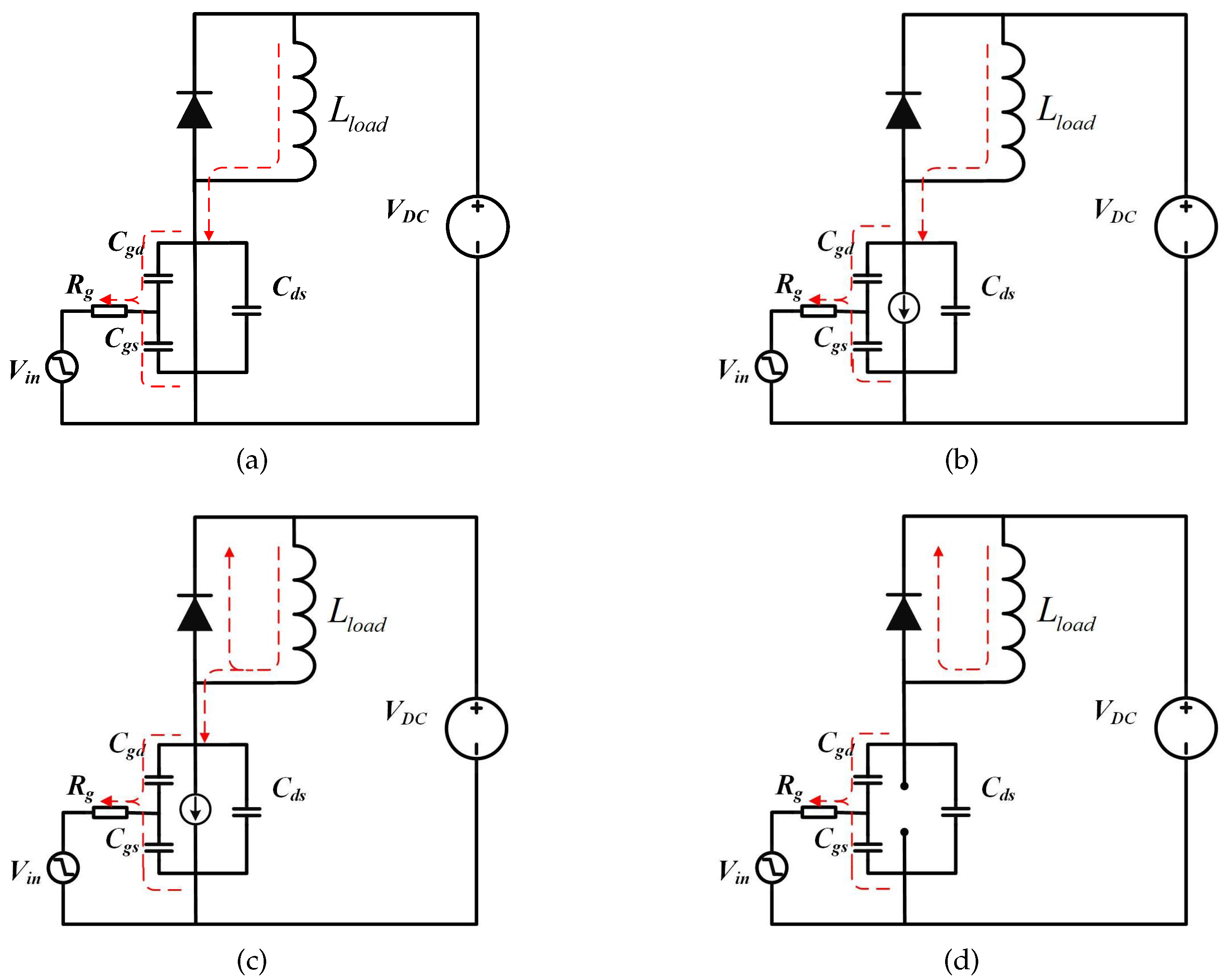
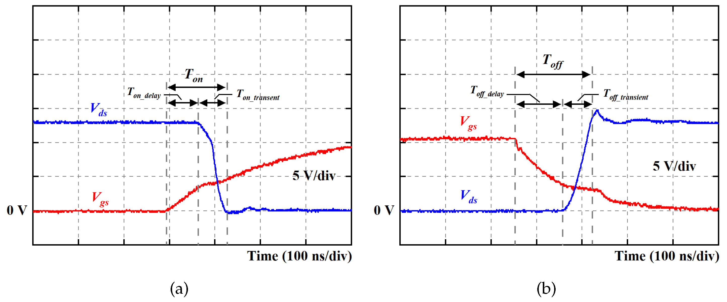
The switching waveform during the turn-on transition of the MOSFET is given in Figure 7. It is noted that the turn-on transition can be divided into four stages. Figure 8 illustrates the equivalent circuit of each stage during the turn-on transition.
Stage 1 ( t 0 t 1 ): In this stage, the gate voltage supply steps from 0 to V G S _ O N . As a result, the gate current ( I g ) charges the gate–source capacitance ( C g s ) of the MOSFET. According to the equivalent circuit of this stage (see Figure 8a), the following relationship can be acquired:
V d s = V D C V g s = V g d + V d s I g = C g d d V g d d t + C g s d V g s d t V G S _ O N = I g R g + V g s
where V g s , V d s , V g d represent the gate–source voltage, drain–source voltage, and gate–drain voltage of the MOSFET, V D C means the dc voltage supply, C g d is the gate–drain capacitance of the MOSFET, and R g stands for gate resistance. According to the operation mechanism of the MOSFET, this stage will continue until V g s reaches the threshold voltage ( V t h ). Therefore, the duration of this stage ( T o n _ d e l a y ) can be obtained as
T o n _ d e l a y = R g C i s s ln V G S _ O N V G S _ O N V t h
where C i s s is the input capacitance of the MOSFET, and it can be defined as
C i s s = C g d + C g s
Thus, it can be observed that the T o n _ d e l a y is nearly not affected by the load current.
Stage 2 ( t 1 t 2 ): In this stage, I g still charges C g s . According to Figure 8b, it is noted that the relationships demonstrated in (33) are still validated in this case. Meanwhile, V g s > V t h , and the channel of the MOSFET begins to conduct. This stage will continue until V g s reaches the miller plateau voltage ( V m i l ), which can be expressed as
V m i l = i L g f s + V t h
where i L refers to the load current, and g f s is considered the transconductance of the MOSFET. Then, based on (33) and (36), the duration of stage 2 ( t o n _ 1 ) can be calculated as
t o n _ 1 = R g C i s s ln V G S _ O N V t h V G S _ O N i L / g f s + V t h
Obviously, the t o n _ 1 is prolonged with the increased load current.
Stage 3 ( t 2 t 3 ): Figure 8c illustrates the equivalent circuit in this stage. It is noted that I g charges C g d , and V g s is clamped ( V g s = V m i l ). This stage will end once V d s drops to zero. Thus, the following relationship can be obtained:
V g s = V g d + V d s = V m i l I g = C g d d V g d d t = C g d d V d s d t V G S _ O N = I g R g + V m i l
Then, the slew rate of V d s can be calculated as
d V d s d t = V G S _ O N V m i l R g C g d
Thus, the duration of stage 3 ( t o n _ 2 ) can be obtained as
t o n _ 2 = V D C · R g · C g d V G S _ O N i L / g f s + V t h
It is obvious that t o n _ 2 is also prolonged with the increased load current. As a result, it can be confirmed that the total transient time ( T o n _ t r a n s i e n t ) during the turn-on process will be increased with the improved load current.
T o n _ t r a n s i e n t = t o n _ 1 + t o n _ 2
Stage 4 ( t 3 t 4 ): Since the switching transient related to T o n finishes at the end of stage 3, stage 4 (see Figure 8) plays a less significant role. As a result, a detailed analysis of this stage can be omitted.

3.2. Turn-Off Process

In this part, we discuss two cases of the turn-off process of the power MOSFET. One is considered a normal turn-off process, and the other one is viewed as a QZCS turn-off process.

3.2.1. Normal Case

The switching waveform during the normal turn-off transition of the MOSFET is given in Figure 9. It is noted that the normal turn-off transition can be divided into four stages. Figure 10 illustrates the equivalent circuit of each stage in the normal turn-off process.
Stage 1 ( t 0 t 1 ): In this stage, the gate voltage supply steps from V G S _ O N to 0. As a result, I g discharges C g s . According to the equivalent circuit of this stage (see Figure 10a), the following relationship can be acquired:
I g = C g d d V g d d t + C g s d V g s d t V g s = V g d + V d s V d s = 0 V g s + I g R g = 0
Since this stage will continue until V g s drops to V m i l , the duration of this stage ( T o f f _ d e l a y ) can be acquired as
T o f f _ d e l a y = R g C i s s ln ( V G S _ O N i L / g f s + V t h )
It is obvious that the T o f f _ d e l a y shrinks with the increased load current.
Stage 2 ( t 1 t 2 ): Once the V g s drops below V m i l , the MOSFET operates in the saturation region. Thus, V d s rises in this stage. According to the equivalent circuit of this stage (see Figure 10b), the following relationship can be acquired:
V g s = V g d + V d s = V m i l I g = C g d d V g d d t = C g d d V d s d t 0 = I g R g + V m i l
Then, the slew rate of V d s can be calculated as
d V d s d t = V m i l R g C g d
It is noted that this stage will end once V d s reaches V D C . As a result, the duration of this stage ( T o f f _ t r a n s i e n t ) can be acquired as
T o f f _ t r a n s i e n t = V D C R g C g d i L / g f s + V t h
Obviously, the T o f f _ d e l a y also reduces with the increased load current.
Stage 3 ( t 2 t 3 ) and Stage 4 ( t 3 t 4 ): Since the switching transient related to T o f f in the normal witching process finishes at the end of stage 2, stages 3 and 4 (see Figure 10c,d) have less significant impacts. As a result, a detailed analysis of stages 3 and 4 can be omitted in this situation.

3.2.2. QZCS Case

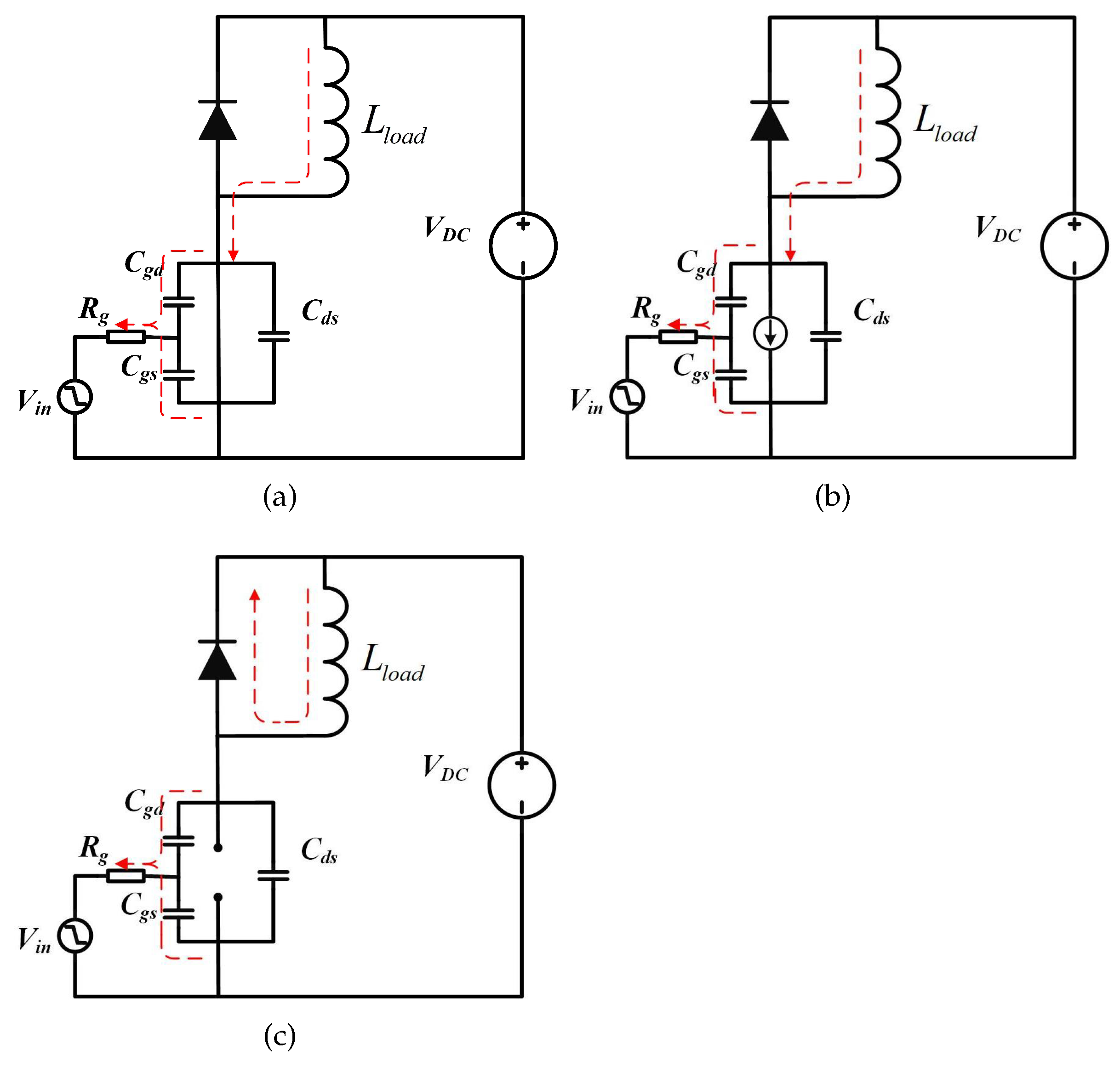
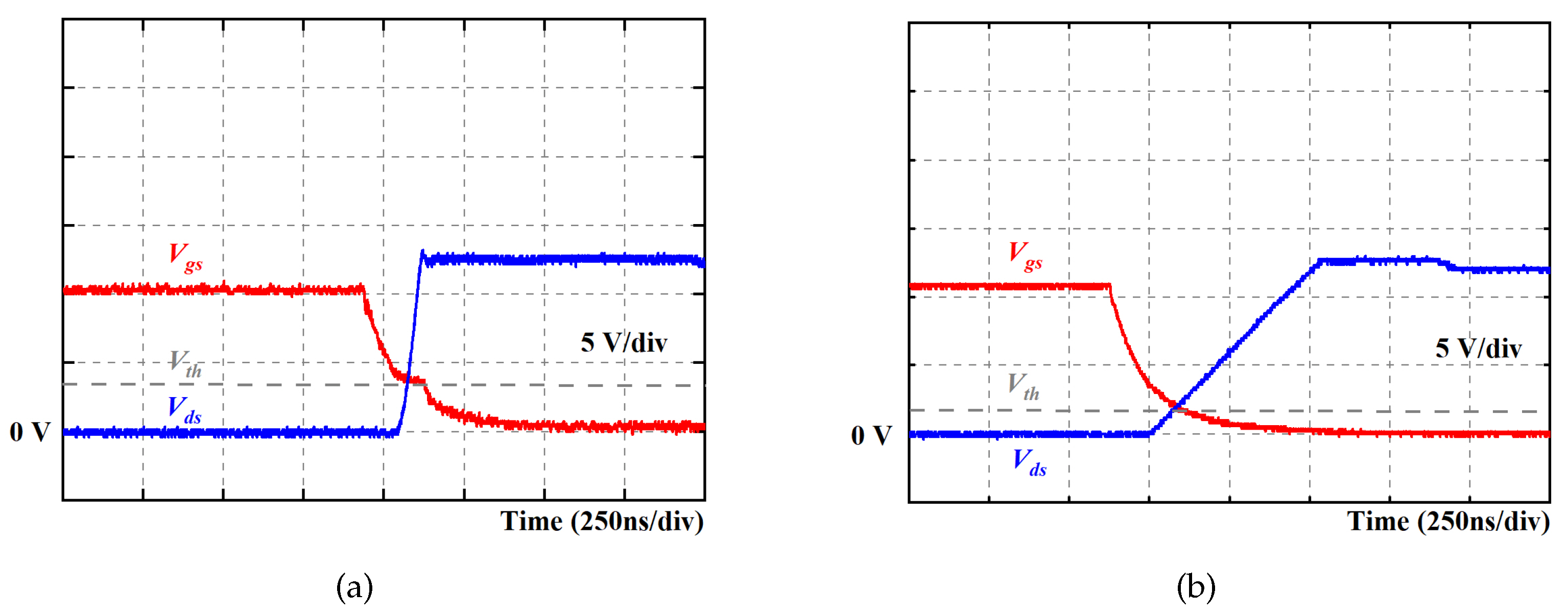
As analyzed in [35], the QZCS turn-off process usually occurs in low-current conditions. The switching waveform during the QZCS turn-off transition of the MOSFET is given in Figure 11. It is noted that the QZCS turn-off transition can be divided into three stages. Figure 12 illustrates the equivalent circuit of each stage in the QZCS turn-off process.
Stage 1 ( t 0 t 1 ): According to Figure 12a, it is noted that this stage is the same as stage 1 in a normal turn-off process. Thus, (43) is still validated in this case.
Stage 2 ( t 1 t 2 ): According to Figure 12b, it is noted that (42) is still suitable in this case. Since this stage will finish once V g s drops below V t h , the duration in this stage ( t o f f _ 1 ) can be acquired as
t o f f _ 1 = R g C i s s ln i L / g f s + V t h V t h
Stage 3 ( t 2 t 3 ): According to the equivalent circuit shown in Figure 12c, it can be noted that the MOSFET enters the cutoff region, and the load current i L charges the output capacitance ( C o s s = C g d + C d s ) of the MOSFET. Thus, it can be obtained that
d V d s d t = i L C o s s
This stage lasts until V d s reaches V D C . Thus, the duration of this stage ( t o f f _ 2 ) can be acquired as
t o f f _ 2 = V D C · C o s s i L
It is obvious that t o n _ 2 is prolonged with the reduced load current. Although the t o f f _ 1 is shrunk with the reduced load current, it can be figured out that the total transient time ( T o f f _ t r a n s i e n t ) during the QZCS turn-off process will be increased with the reduced load current because t o f f _ 1 < < t o f f _ 2 .
T o f f _ t r a n s i e n t = t o f f _ 1 + t o f f _ 2
Figure 13 shows the switching waveforms (including V g s and V d s ) of the power MOSFET in the normal and QZCS turn-off processes, which are in good accordance with the above analysis. The switching time ( T o n and T o f f ) for the dead-time effect compensation depends on the load current.

3.3. Relationships between T o n / T o f f and Load Current

According to the switching process of the MOSFET elaborated above, the relationships between T o n / T o f f and i L are summarized in Table 1 and Table 2. In general, the T o n increases with the increased i L , and the T o f f decreases with the increased i L . However, the relationship between T c o m and i L cannot easily be acquired with the results listed in Table 1 and Table 2 based on (31), because the variation in T o n is contrary to that of T o f f with the varied i L . As a result, the T c o m should be obtained according to the specific values of T o n and T o f f measured with MPT, which is elaborated in the following section.

4. Switching Characteristic Evaluation of the MOSFET Based on the Multipulse Test

4.1. Principle of the MPT

A multipulse test (MPT) is implemented to evaluate the switching characteristics of the power MOSFET in motor drives.
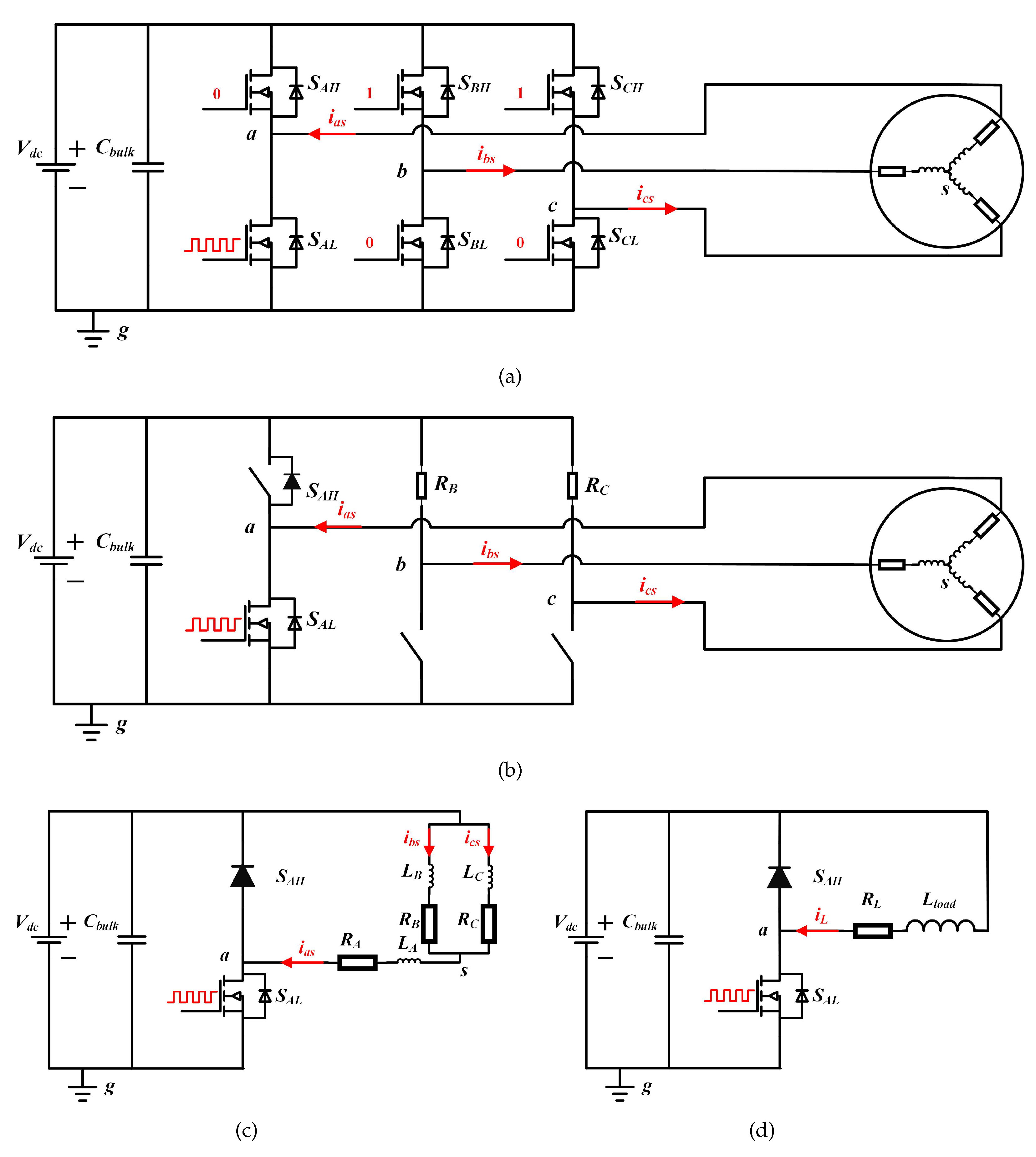
Figure 14a illustrates the scheme of the MPT circuit when load current i L > 0. In this case, S A L , S B H , and S C H are turned off and S B L and S C L are turned on. S A H is regulated by the PWM signal. According to the principle of circuit theory, the scheme of the MPT can be further simplified as the circuit shown in Figure 14c when i L > 0. The rotation speed of the motor is set to zero during the whole test process. The motor in this condition can be considered an R-L load.
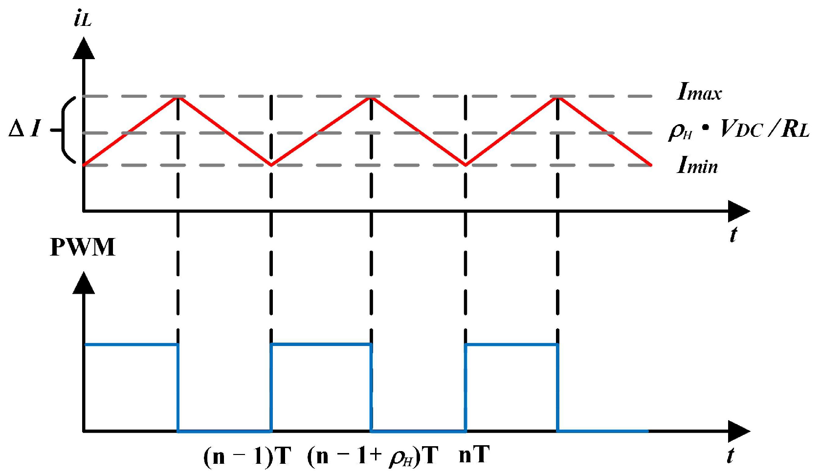
According to Figure 14d and Figure 15, the following relationships can be obtained when ( n 1 ) T t < ( n 1 + ρ H )T
L l o a d d i L d t + R L · i L t = V D C i L [ ( n 1 ) T ] = I min
where I m i n is the minimum value of i L in a complete switching period, and T refers to the switching period. Similarly, (52) can be acquired when ( n 1 + ρ H )T ≤ t < nT.
L l o a d d i L d t + R L · i L t = 0 i L [ ( n 1 + ρ H ) T ] = I max
In which I m a x means the maximum value of i L in a complete switching period, and ρ H is the duty factor. Thus, the following relationship can be acquired based on (51) and (52):
i L t = I min V D C R L e R L L l o a d t n 1 T + V D C R L I max e R L L l o a d t n 1 + ρ H T , , n 1 T < t n 1 + ρ H T n 1 + ρ H T < t n T
Then, it can be obtained that
I max = i L [ ( n 1 + ρ H ) T ] = ( I min V D C R L ) e R L L l o a d ρ H T + V D C R L I min = i L ( n T ) = I max e R L L l o a d ( 1 ρ H ) T
Finally, the following relationship can be established:
I max = V D C ( 1 e R L L l o a d ρ H T ) R L ( 1 e R L L l o a d T ) I min = V D C ( e R L L l o a d ( 1 ρ H ) T e R L L l o a d T ) R L ( 1 e R L L l o a d T )
The average load current during MPT can be calculated as
i ¯ L = I max + I min 2 ρ H · V D C R L
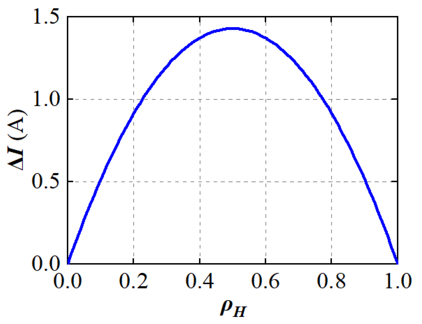
In the MPT, the MOSFET turns on when i L = I m i n , and it turns off when i L = I m a x . In this case, V D C = 12 V, T = 50 μ s, R L = 1.5 R s = 16.5 m Ω ( R s : stator resistance of the motor), L l o a d = 1.5 L s = 105 μ H ( L s : stator inductance of the motor), and the current deviation ( Δ I ) between I m a x and I m i n can be acquired based on (55). According to Figure 16, it is noted that the maximum value of Δ I is no more than 1.5 A. Since the rated current in this work is 80 A, the value of ρ H is less than 0.11. It is obvious that Δ I is no more than 0.5 A when i L varies from 0 to 80 A, which impacts the switching performance of the power MOSFET slightly. Thus, the switching characteristic of the MOSFET with the varied load current can be obtained with the duty factor ( ρ H ) selected based on (56).
Figure 17a illustrates the scheme of the MPT circuit when the load current i L < 0. In this condition, S B H and S C H are turned on, and S A H , S B L , and S C L are turned off. S A L is regulated by the PWM signal. According to the principle of circuit theory, the scheme of the MPT can be further simplified as the circuit shown in Figure 17d when i L < 0. Similarly, the average value of the load current can be regulated by controlling the duty factor ( ρ H ) of the PWM signal for S A L , which can be expressed as
i ¯ L ρ H · V D C R L

4.2. Test Results of MPT

With the regulation of the duty factor ρ , the switching characteristics of the MOSFET with the varied i L can be obtained. Figure 18 shows the switching waveforms of the MOSFET during turn-on and turn-off transitions in a complete switching period of MPT when i L = 10 A. The values of T o n _ d e l a y , T o n _ t r a n s i e n t , T o f f _ d e l a y , and T o f f _ t r a n s i e n t can be obtained accordingly. Table 3 summaries the measured T o n _ d e l a y , T o n _ t r a n s i e n t , T o f f _ d e l a y , and T o f f _ t r a n s i e n t based on MPT with the varied i L .
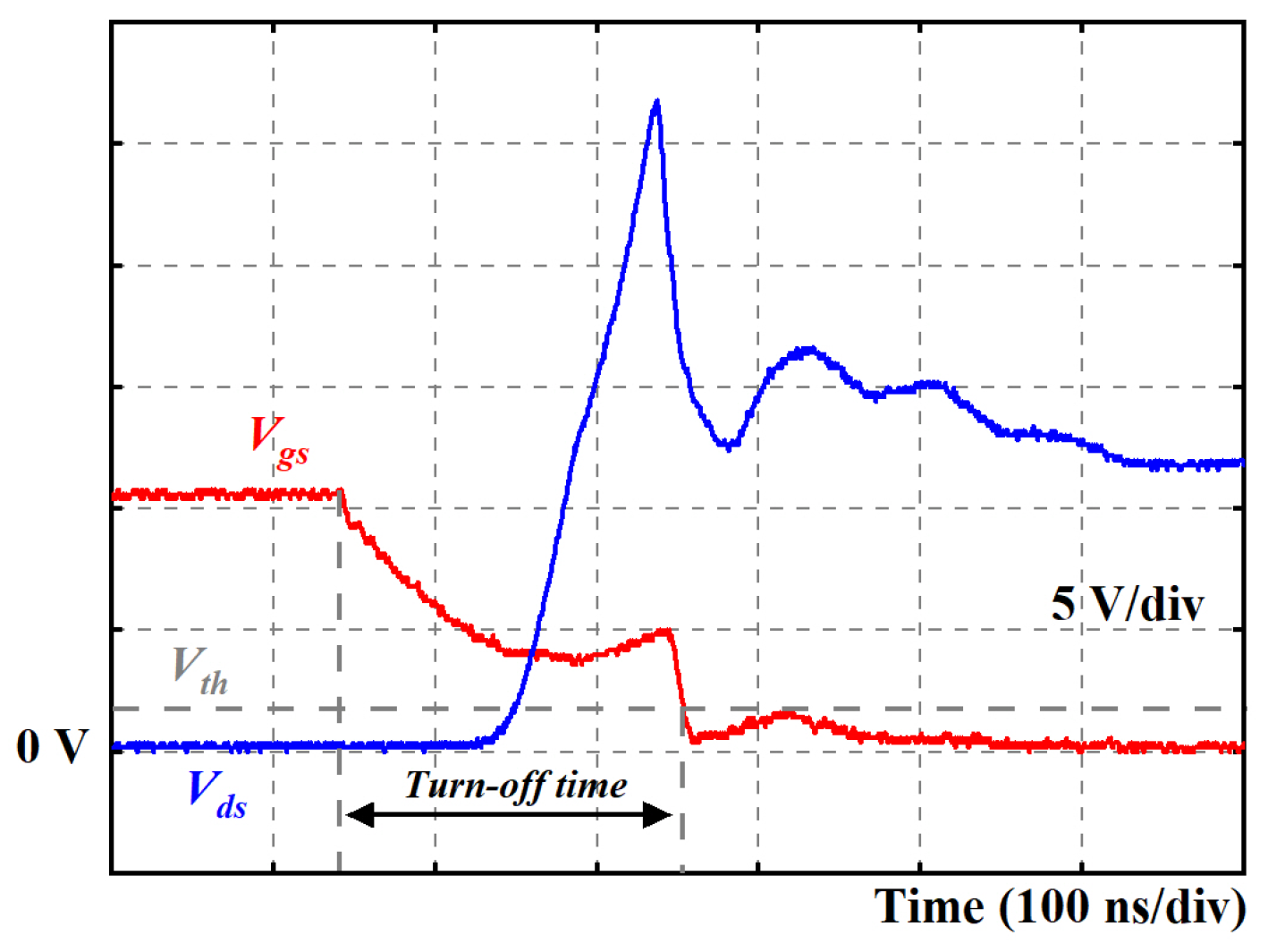
Figure 19 illustrates the switching waveforms of V g s and V d s of the MOSFET during the turn-off transition when i L = 80 A (the worst case in this work). It can be observed that the turn-off time is about 200 ns. Normally, the dead time is set as 2 to 5 times the turn-off time of the power MOSFET, which can ensure the safety and reliability of the motor drives. As a result, the dead time is fixed as 1 μ s in this work.
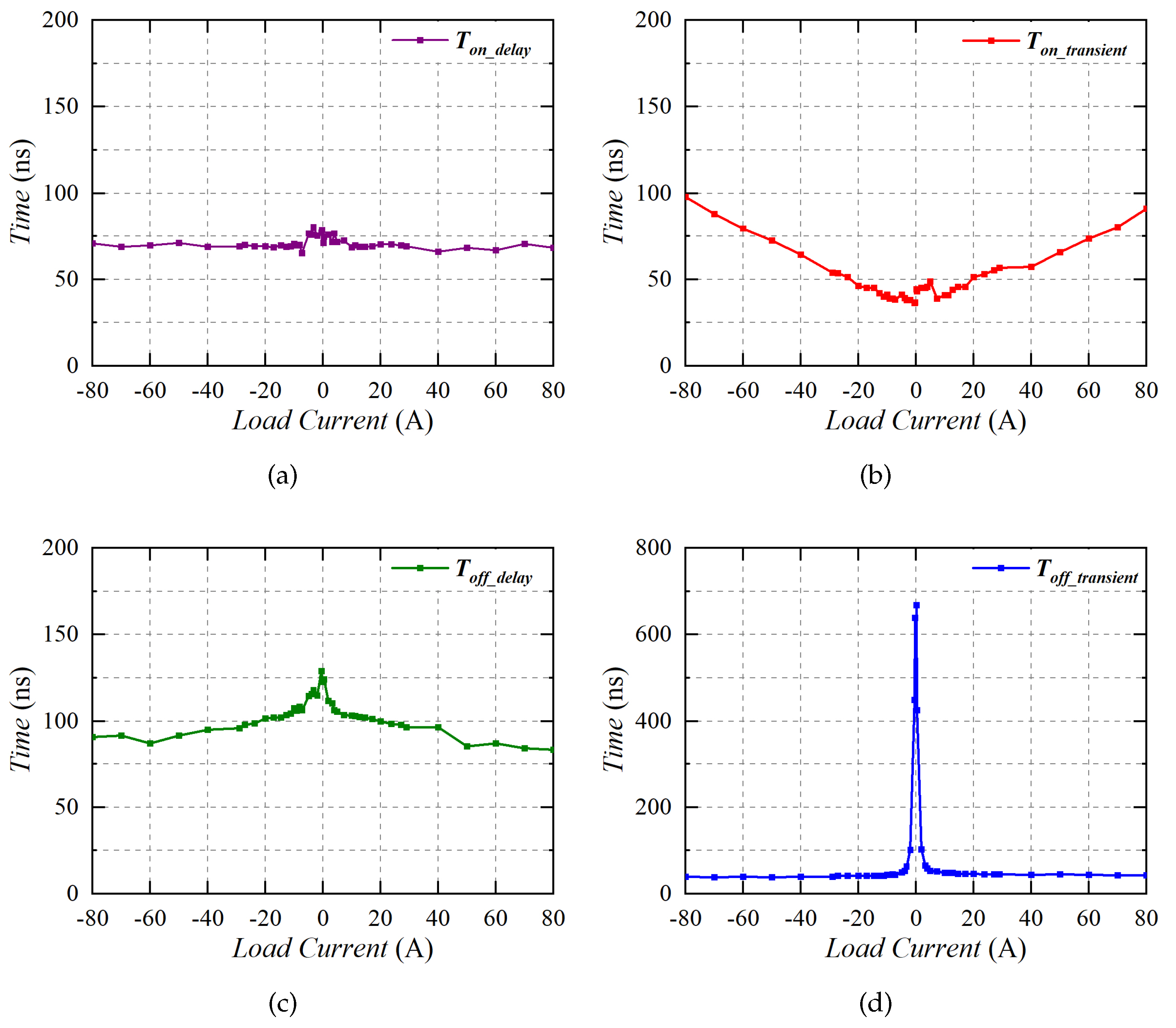
The detailed switching characteristics of the power MOSFET with the varied load current are given in Figure 20. It can be clearly observed that the value of T o n _ d e l a y is around 70 ns, and T o n _ t r a n s i e n t increases with improved i L . Meanwhile, both T o f f _ d e l a y and T o f f _ t r a n s i e n t decrease with the increased i L . Obviously, the MPT results are in good accordance with the analysis discussed in Section 3. Then, the compensation time T c o m can finally be obtained by calculating (31) with the combination of the MPT results (see Table 3) and linear interpolation method.

5. Experiment Verification

5.1. Experiment Bench

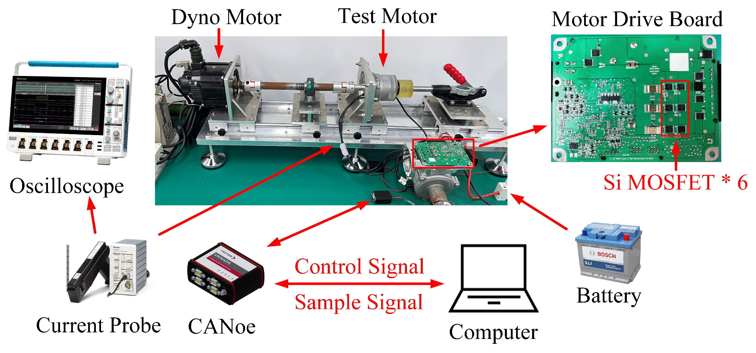
Figure 21 shows the experiment bench of the PMSM. The dynamo motor offers a constant rotation speed ( ω r ), and the test PMSM operates in the current control mode. A 12 V battery offers the dc power supply, and the phase current waveform of the PMSM can be acquired with a combination of a current probe TCP0150 (20 MHz, 150 A) and an oscilloscope with a high sampling rate (MSO34). In addition, the control unit of the motor drives communicates with the host computer through the CAN bus. In this work, a low-voltage Si MOSFET (IPC100N04S5 from Infineon, 40 V/100 A) is selected, and the gate resistors are set to 20 Ω for the turn-on process and 10 Ω for the turn-off process. In the test, the stator current i L is set to 10, 20, 40, and 80 A. Since L d = L q , the i d = 0 control strategy is adopted in this case. The rotation speed ( ω r ) of the motor is set to 10, 30, and 50 rad/s. The parameters of the test motor are listed in Table 4.

5.2. Experiment Results

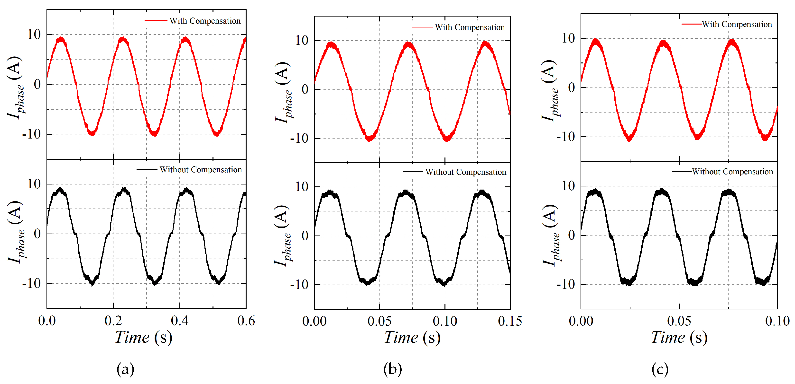
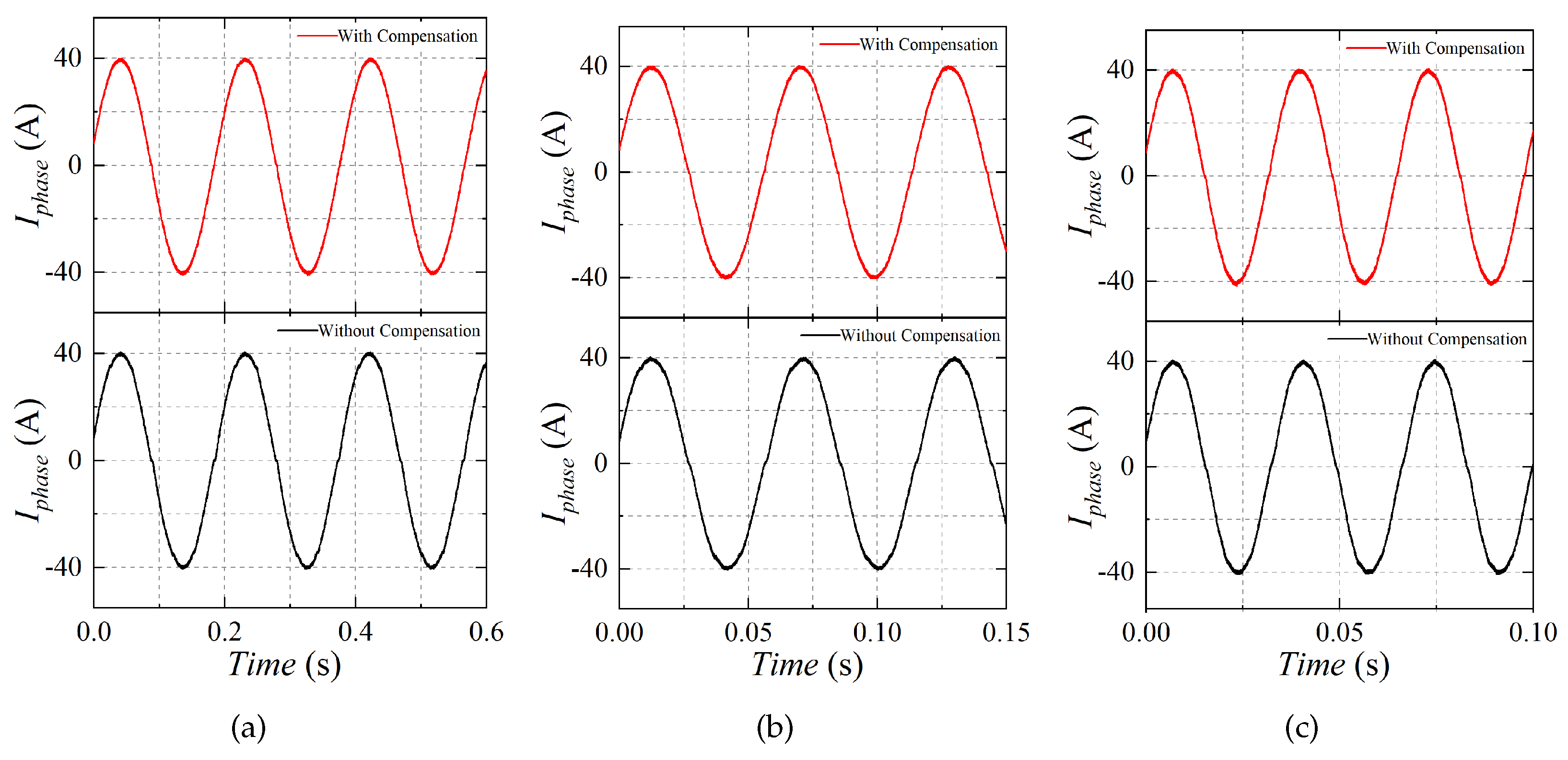
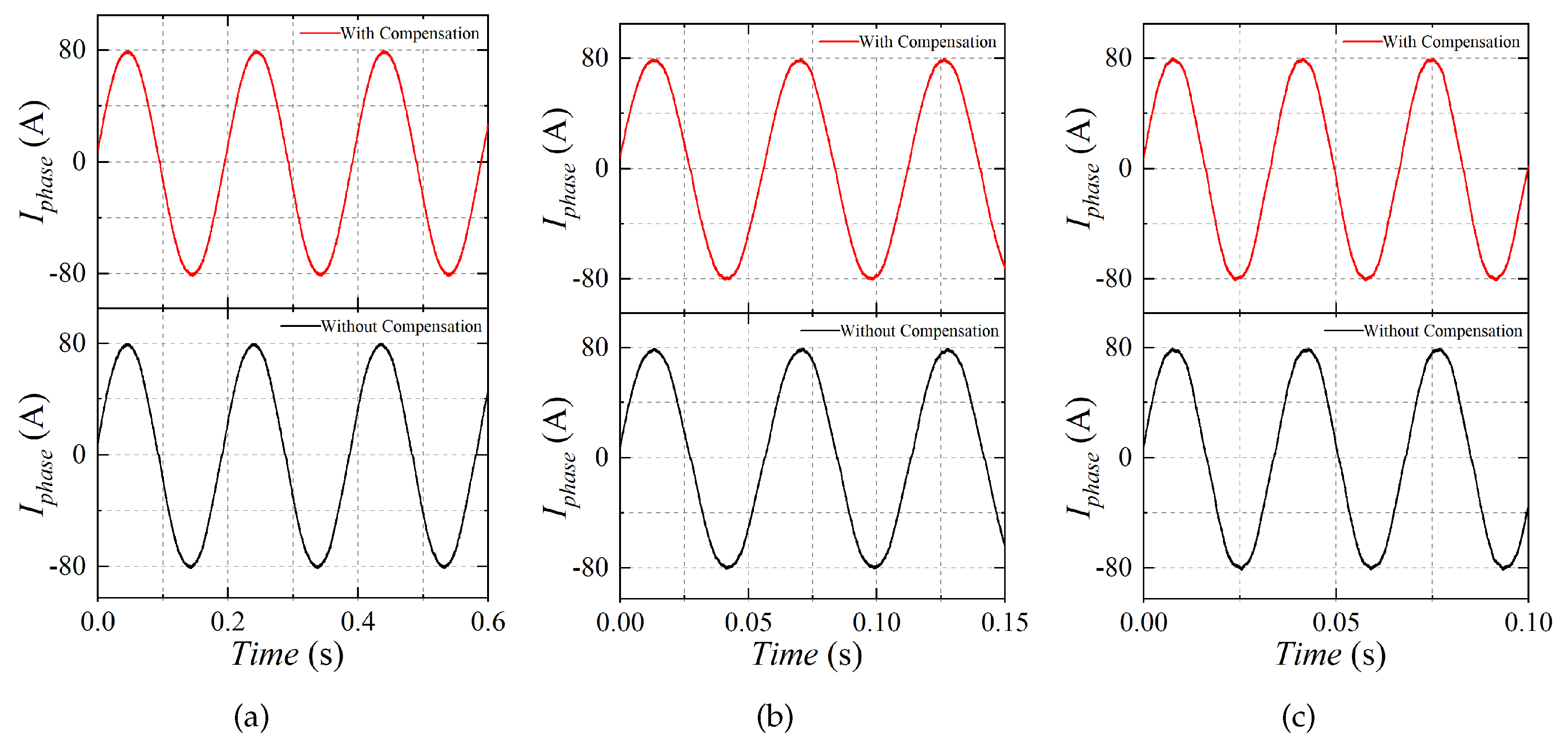
The dead time ( T d ) is set as 1 μ s for the whole test. Figure 22, Figure 23, Figure 24 and Figure 25 illustrate the time-domain waveform of the phase current with and without the dead-time compensation when i L = 10, 20, 40, and 80 A and ω r = 10, 30, and 50 rad/s. It is obvious that the current distortion was significantly reduced with the dead-time compensation, especially in the low modulation index ( M i ) region (low rotation speed with slight load). The impacts of the dead-time effect become obvious in this case. As a result, the dead-time compensation method seems more effective with a smaller M i . Meanwhile, the current distortion degrades gradually with the increase in M i , whether the compensation is considered or not.
Figure 26, Figure 27, Figure 28 and Figure 29 illustrate the spectrum of the phase current with and without the dead-time compensation when i L = 10, 20, 40, and 80 A and ω r = 10, 30, and 50 rad/s, which indicates that the 5th-, 7th-, and 11th-order harmonics were significantly reduced with the proposed dead-time compensation method. However, the suppression of the harmonic based on the compensation method degrades with the increased rotation speed in heavy loads. It is noted that the 5th-order harmonic is only reduced by 14% with the dead-time compensation method when i L = 80 A and ω r = 50 rad/s, which can be attributed to the harmonic characteristics of the PWM strategy. Usually, the space vector PWM (SVPWM) is adopted in most cases. With the increased current and rotation speed, M i improves accordingly. As stated in [36], the harmonics become serious when an increased M i once SVPWM is adopted.
According to the spectrum of the phase current, the relationship between total harmonic distortion (THD) value and variation in i s with different ω r can be obtained (see Figure 30). It can be noted that the THD value is 12.66% when the motor operates with i L = 10 A and ω r = 10 rad/s without dead-time compensation, which reflects the more serious current harmonics, as well as the torque ripples. With the dead-time compensation, the THD value is reduced to 3.94%. As a result, the current harmonics, as well as the torque ripple, can be reduced accordingly. On the contrary, the THD value is only 2.93% when i L = 80 A and ω r = 10 rad/s without the dead-time compensation, and it reduces to 0.85% with the dead-time compensation. It is noted that the dead-time compensation can reduce the current harmonics as well as the torque ripples significantly in light load operation. However, the suppression of the THD value reduces with the increased M i , which can be attributed to the following reasons. For one thing, the dead-time effect is reduced in the high modulation index region, which causes less serious distortion without any compensation. It can be clearly observed that the THD value reduces by nearly 10% when the current varies from 10 to 80 A without any compensation. Another reason is that the THD value increases with the increased M i due to the performance of the SVPWM strategy [36], which results in the reduced suppression effect.
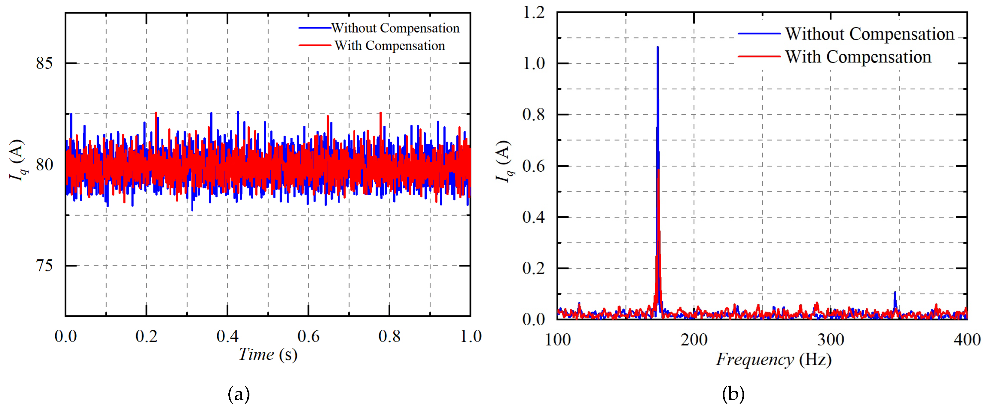
Figure 31 and Figure 32 illustrate the time-domain waveform and spectrum of the q-axis current with and without the dead-time compensation when i L = 80 A (rated torque) and ω r = 50 rad/s, as well as when i L = 40 A (half rated torque) and ω r = 10 rad/s. It is obvious that the 6th-order harmonics in the q-axis current have been largely reduced, which is also critical to the torque ripples.
Figure 33 summarizes the impacts of the dead-time compensation method on the 6th-order harmonic in the q-axis current. It can be noted that the 6th-order harmonic was effectively suppressed whether the M i was large or small, which resulted in alleviated torque ripples, as well as reduced high-order noise.

6. Conclusions

In this paper, a dynamic dead-time compensation method is proposed based on the switching characteristic of the power MOSFET for a PMSM drive system. Compared with other methods, the proposed method is focused on the switching characteristics of the power MOSFET, which directly determines the value of the compensation time. In addition, the relationship between the switching time of the MOSFET and the load current was comprehensively elaborated and verified effectively based on the multipulse test, which is critical for acquiring a suitable compensation time. According to the relative experiment results, the following can be confirmed:
  • The proposed compensation method shows a perfect performance in current distortion suppression with a low modulation index. With the increased modulation index, the dead-time effect is reduced, which makes the suppression of the current distortion not apparent;
  • The proposed compensation method reduces the 5th-, 7th-, and 11th-order harmonics significantly in the low modulation index region, as well as the THD values. However, the reduction ratio of the harmonics and the THD values degrades with the increased modulation index, which can mainly be attributed to the harmonic characteristics of the SVPWM strategy adopted in the motor drives;
  • The proposed compensation method can alleviate the 6th-order harmonic in the q-axis current, whether the modulation index is large or small. As a result, reduced torque ripples, as well as attenuated high-order noises, can be achieved, which is essential for enhancing the performance of the motor drives.

Author Contributions

Conceptualization, X.L. and Y.W.; Methodology, X.L. and Y.W.; Software, Y.W.; Validation, X.L. and Y.W.; Investigation, X.L.; Resources, L.W.; Writing—original draft, X.L.; Writing—review & editing, Y.W.; Supervision, S.Y.; Project administration, L.W.; Funding acquisition, H.L. All authors have read and agreed to the published version of the manuscript.

Funding

This research received no external funding.

Data Availability Statement

The data presented in this study are available in this article.

Conflicts of Interest

Author Yingzhe Wu and Lisheng Wang were employed by the company Shanghai Gatek Automotive Electronics Co., Ltd. The remaining authors declare that the research was conducted in the absence of any commercial or financial relationships that could be construed as a potential conflict of interest.

References

  1. Zhao, Y.F.; Yan, F.W.; Du, C.Q. Fast start-up control method of PMSM based on incremental photoelectric encoder. In Proceedings of the IET International Conference on Information Science and Control Engineering 2012 (ICISCE 2012), Shenzhen, China, 7–9 December 2012; pp. 1–4. [Google Scholar]
  2. Khanh, P.Q.; Dat, N.T.; Anh, H.P.H. Optimal Fuzzy-PI PMSM Speed Control Using Evolutionary DE Algorithm Implemented on DSP Controller. In Proceedings of the 2023 International Conference on System Science and Engineering (ICSSE), Ho Chi Minh City, Vietnam, 27–28 July 2023; pp. 206–211. [Google Scholar]
  3. Zhong, L.; Rahman, M.F. Analysis of direct torque control in permanent magnet synchronous motor drives. IEEE Trans. Power Electron. 1997, 12, 528–536. [Google Scholar] [CrossRef]
  4. Liu, H.; Li, S. Speed Control for PMSM Servo System Using Predictive Functional Control and Extended State Observer. IEEE Trans. Ind. Electron. 2012, 59, 1171–1183. [Google Scholar] [CrossRef]
  5. Li, S.; Liu, Z. Adaptive Speed Control for Permanent-Magnet Synchronous Motor System with Variations of Load Inertia. IEEE Trans. Ind. Electron. 2009, 56, 3050–3059. [Google Scholar]
  6. Khanh, P.Q.; Anh, H.P.H. Hybrid optimal fuzzy Jaya technique for advanced PMSM driving control. Electr. Eng. 2023, 105, 3629–3646. [Google Scholar] [CrossRef]
  7. Lei, J.; Fang, S.; Huang, D.; Wang, Y. Enhanced Deadbeat Predictive Current Control for PMSM Drives Using Iterative Sliding Mode Observer. IEEE Trans. Power Electron. 2023, 38, 13866–13876. [Google Scholar] [CrossRef]
  8. Seo, J.H.; Choi, C.H.; Hyun, D.S. A new simplified space-vector PWM method for three-level inverters. IEEE Trans. Power Electron. 2001, 16, 545–550. [Google Scholar]
  9. Casadei, D.; Profumo, F.; Serra, G.; Tani, A. FOC and DTC: Two viable schemes for induction motors torque control. IEEE Trans. Power Electron. 2002, 17, 779–787. [Google Scholar] [CrossRef]
  10. Singh, G.K.; Nam, K.; Lim, S.K. A simple indirect field-oriented control scheme for multiphase induction machine. IEEE Trans. Ind. Electron. 2005, 52, 1177–1184. [Google Scholar] [CrossRef]
  11. Rodriguez, J.; Kennel, R.M.; Espinoza, J.R.; Trincado, M.; Silva, C.A.; Rojas, C.A. High-Performance Control Strategies for Electrical Drives: An Experimental Assessment. IEEE Trans. Ind. Electron. 2012, 59, 812–820. [Google Scholar] [CrossRef]
  12. Xu, F.; Liu, J.; Zhang, X. Analysis of Deadtime Effects and Optimum Deadtime Control for Bidirectional Inductive Power Transfer Converters. IEEE Trans. Ind. Electron. 2023, 1–9. [Google Scholar] [CrossRef]
  13. Munoz, A.; Lipo, T. On-line dead-time compensation technique for open-loop PWM-VSI drives. IEEE Trans. Power Electron. 1999, 14, 683–689. [Google Scholar] [CrossRef]
  14. Choi, J.W.; Sul, S.K. Inverter output voltage synthesis using novel dead time compensation. IEEE Trans. Power Electron. 1996, 11, 221–227. [Google Scholar] [CrossRef]
  15. Tong, S.; Li, Y. Adaptive Fuzzy Output Feedback Control of MIMO Nonlinear Systems with Unknown Dead-Zone Inputs. IEEE Trans. Fuzzy Syst. 2013, 21, 134–146. [Google Scholar] [CrossRef]
  16. Jeong, S.G.; Park, M.H. The analysis and compensation of dead-time effects in PWM inverters. IEEE Trans. Ind. Electron. 1991, 38, 108–114. [Google Scholar] [CrossRef]
  17. Dolguntseva, I.; Krishna, R.; Soman, D.E.; Leijon, M. Contour-Based Dead-Time Harmonic Analysis in a Three-Level Neutral-Point-Clamped Inverter. IEEE Trans. Ind. Electron. 2015, 62, 203–210. [Google Scholar] [CrossRef]
  18. Yuruk, H.; Keysan, O.; Ulutas, B. Comparison of the Effects of Nonlinearities for Si MOSFET and GaN E-HEMT Based VSIs. IEEE Trans. Ind. Electron. 2021, 68, 5606–5615. [Google Scholar] [CrossRef]
  19. Xiang, D.; Yang, J.; Hao, Y.; Xu, G. Two-Parameter Identification Method of Deadtime Effect Voltage Error Model during Self-Commission. IEEE Trans. Power Electron. 2023, 38, 15904–15920. [Google Scholar] [CrossRef]
  20. Wu, M.; Zhao, R.; Tang, X. Study of Vector-Controlled Permanent Magnet Synchronous Motor at Low Speed and Light Load. Trans. China Electrotech. Soc. 2005, 07, 87–92. [Google Scholar]
  21. Cao, X.; Fan, L. Dead-Time Compensation for PMSM Drive Based on Neuro-Fuzzy Observer. In Proceedings of the 2008 Fourth International Conference on Natural Computation, Jinan, China, 18–20 October 2008; Volume 2, pp. 46–50. [Google Scholar]
  22. Lee, D.H.; Ahn, J.W. A Simple and Direct Dead-Time Effect Compensation Scheme in PWM-VSI. IEEE Trans. Ind. Appl. 2014, 50, 3017–3025. [Google Scholar] [CrossRef]
  23. El-Daleel, M.S.; Mahgoub, O.; Elshafei, A.L.; Mahgoub, A. Inverter dead-time and non-linearity rejection using a wide bandwidth current controller for PMSM drives with a speed sensor. In Proceedings of the 2016 Eighteenth International Middle East Power Systems Conference (MEPCON), Cairo, Egypt, 27–29 December 2016; pp. 687–692. [Google Scholar]
  24. Urasaki, N.; Senjyu, T.; Kinjo, T.; Funabashi, T.; Sekine, H. Dead-time compensation strategy for permanent magnet synchronous motor drive taking zero-current clamp and parasitic capacitance effects into account. In Proceedings of the 30th Annual Conference of IEEE Industrial Electronics Society, Busan, Republic of Korea, 2–6 November 2004; Volume 152, pp. 845–853. [Google Scholar]
  25. Urasaki, N.; Senjyu, T.; Uezato, K.; Funabashi, T. Adaptive Dead-Time Compensation Strategy for Permanent Magnet Synchronous Motor Drive. IEEE Trans. Energy Convers. 2007, 22, 271–280. [Google Scholar] [CrossRef]
  26. Urasaki, N.; Senjyu, T.; Uezato, K.; Funabashi, T. An adaptive dead-time compensation strategy for voltage source inverter fed motor drives. IEEE Trans. Power Electron. 2005, 20, 1150–1160. [Google Scholar] [CrossRef]
  27. Li, C.; Gu, Y.; Li, W.; He, X.; Dong, Z.; Chen, G.; Ma, C.; Zhang, L. Analysis and compensation of dead-time effect considering parasitic capacitance and ripple current. In Proceedings of the 2015 IEEE Applied Power Electronics Conference and Exposition (APEC), Charlotte, NC, USA, 15–19 March 2015; pp. 1501–1506. [Google Scholar]
  28. Zhang, Z.; Xu, L. Dead-Time Compensation of Inverters Considering Snubber and Parasitic Capacitance. IEEE Trans. Power Electron. 2014, 29, 3179–3187. [Google Scholar] [CrossRef]
  29. Tang, Z.; Akin, B. Suppression of Dead-Time Distortion Through Revised Repetitive Controller in PMSM Drives. IEEE Trans. Energy Convers. 2017, 32, 918–930. [Google Scholar] [CrossRef]
  30. Hwang, S.H.; Kim, J.M. Dead Time Compensation Method for Voltage-Fed PWM Inverter. IEEE Trans. Energy Convers. 2010, 25, 1–10. [Google Scholar] [CrossRef]
  31. Kim, S.Y.; Park, S.Y. Compensation of Dead-Time Effects Based on Adaptive Harmonic Filtering in the Vector-Controlled AC Motor Drives. IEEE Trans. Ind. Electron. 2007, 54, 1768–1777. [Google Scholar] [CrossRef]
  32. Yang, K.; Yang, M.; Lang, X.; Lang, Z.; Xu, D. An adaptive dead-time compensation method based on Predictive Current Control. In Proceedings of the 2016 IEEE 8th International Power Electronics and Motion Control Conference (IPEMC-ECCE Asia), Hefei, China, 22–26 May 2016; pp. 121–125. [Google Scholar]
  33. Gui, H.; Zhang, Z.; Ren, R.; Chen, R.; Niu, J.; Tolbert, L.M.; Wang, F.; Blalock, B.J.; Costinett, D.J.; Choi, B.B. SiC MOSFET Versus Si Super Junction MOSFET-Switching Loss Comparison in Different Switching Cell Configurations. In Proceedings of the 2018 IEEE Energy Conversion Congress and Exposition (ECCE), Portland, OR, USA, 23–27 September 2018; pp. 6146–6151. [Google Scholar]
  34. Wang, G.; Wang, F.; Magai, G.; Lei, Y.; Huang, A.; Das, M. Performance comparison of 1200 V 100 A SiC MOSFET and 1200 V 100 A silicon IGBT. In Proceedings of the 2013 IEEE Energy Conversion Congress and Exposition (ECCE), Denver, CO, USA, 15–19 September 2013; pp. 3230–3234. [Google Scholar]
  35. Xie, Y.; Chen, C.; Yan, Y.; Huang, Z.; Kang, Y. Investigation on Ultra-low Turn-off Losses Phenomenon for SiC MOSFETs with Improved Switching Model. IEEE Trans. Power Electron. 2021, 36, 9382–9397. [Google Scholar] [CrossRef]
  36. Hava, A.; Kerkman, R.; Lipo, T. A high-performance generalized discontinuous PWM algorithm. IEEE Trans. Ind. Appl. 1998, 34, 1059–1071. [Google Scholar] [CrossRef]
Figure 1. Scheme of a typical PMSM drive system.
Electronics 12 04855 g001
Figure 2. Scheme of FOC combined with SVPWM in PMSM drives.
Electronics 12 04855 g002
Figure 3. Phase node “a” to ground “g” voltage V a g in ideal conditions.
Electronics 12 04855 g003
Figure 4. Phase node “a” to ground “g” voltage V a g of motor in actual conditions. (a) i a s > 0. (b) i a s < 0.
Electronics 12 04855 g004
Figure 5. Time-domain waveform of voltage deviation in A-B-C reference.
Electronics 12 04855 g005
Figure 6. Time-domain waveform of voltage deviation in α - β reference frame.
Electronics 12 04855 g006
Figure 7. The switching waveform of the MOSFET during turn-on transition.
Electronics 12 04855 g007
Figure 8. Equivalent circuits for turn-on stage, (a) Stage 1, (b) Stage 2, (c) Stage 3, (d) Stage 4.
Electronics 12 04855 g008
Figure 9. The voltage and current waveforms during turn-off stage in normal cases.
Electronics 12 04855 g009
Figure 10. Equivalent circuits for turn-off stage in normal cases, (a) Stage 1, (b) Stage 2, (c) Stage 3, (d) Stage 4.
Electronics 12 04855 g010
Figure 11. The voltage and current waveforms during turn-off stage in the QZCS case.
Electronics 12 04855 g011
Figure 12. Equivalent circuits for turn-off stages in the QZCS case, (a) Stage 1, (b) Stage 2, (c) Stage 3.
Electronics 12 04855 g012
Figure 13. Switching waveforms in normal and QZCS turn-off processes: (a) Normal case ( i L = 5 A). (b) QZCS case ( i L = 0.5 A).
Electronics 12 04855 g013
Figure 14. Scheme of the MPT circuit when i L > 0, (a) Circuit of MPT, (b) Equivalent circuit 1 of MPT, (c) Equivalent circuit 2 of MPT, (d) Equivalent circuit 3 of MPT.
Electronics 12 04855 g014
Figure 15. Typical waveform of the load current i L in MPT ( i L > 0).
Electronics 12 04855 g015
Figure 16. Current deviation between I m a x and I m i n when duty factor ( ρ H ) varies from 0 to 1.
Electronics 12 04855 g016
Figure 17. Scheme of the MPT circuit when i L < 0, (a) Circuit of MPT, (b) Equivalent circuit 1 of MPT, (c) Equivalent circuit 2 of MPT, (d) Equivalent circuit 3 of MPT.
Electronics 12 04855 g017
Figure 18. The switching waveforms of the MOSFET during turn-on and turn-off transitions of the MOSFET in a complete period of MPT when i L = 10 A: (a) Turn-on transition, (b) Turn-off transition.
Electronics 12 04855 g018
Figure 19. The switching waveforms of the MOSFET during turn-off transition when i L = 80 A.
Electronics 12 04855 g019
Figure 20. The switching characteristics of the power MOSFET with the varied load current. (a) T o n _ d e l a y , (b) T o n _ t r a n s i e n t , (c) T o f f _ d e l a y , (d) T o f f _ t r a n s i e n t .
Electronics 12 04855 g020
Figure 21. Experiment Bench.
Electronics 12 04855 g021
Figure 22. Time-domain waveform of the phase current with and without the dead-time compensation when i L = 10 A, (a) ω r = 10 rad/s, (b) ω r = 30 rad/s, (c) ω r = 50 rad/s.
Electronics 12 04855 g022
Figure 23. Time-domain waveform of the phase current with and without the dead-time compensation when i L = 20 A, (a) ω r = 10 rad/s, (b) ω r = 30 rad/s, (c) ω r = 50 rad/s.
Electronics 12 04855 g023
Figure 24. Time-domain waveform of the phase current with and without the dead-time compensation when i L = 40 A, (a) ω r = 10 rad/s, (b) ω r = 30 rad/s, (c) ω r = 50 rad/s.
Electronics 12 04855 g024
Figure 25. Time-domain waveform of the phase current with and without the dead-time compensation when i L = 80 A, (a) ω r = 10 rad/s, (b) ω r = 30 rad/s, (c) ω r = 50 rad/s.
Electronics 12 04855 g025
Figure 26. Spectrum of phase current with and without the dead-time compensation when i L = 10 A, (a) ω r = 10 rad/s, (b) ω r = 30 rad/s, (c) ω r = 50 rad/s.
Electronics 12 04855 g026
Figure 27. Spectrum of phase current with and without the dead-time compensation when i L = 20 A, (a) ω r = 10 rad/s, (b) ω r = 30 rad/s, (c) ω r = 50 rad/s.
Electronics 12 04855 g027
Figure 28. Spectrum of phase current with and without the dead-time compensation when i L = 40 A, (a) ω r = 10 rad/s, (b) ω r = 30 rad/s, (c) ω r = 50 rad/s.
Electronics 12 04855 g028
Figure 29. Spectrum of phase current with and without the dead-time compensation when i L = 80 A, (a) ω r = 10 rad/s, (b) ω r = 30 rad/s, (c) ω r = 50 rad/s.
Electronics 12 04855 g029
Figure 30. Relationship between THD value and variation in the stator current with different rotation speeds: (a) ω r = 10 rad/s. (b) ω r = 30 rad/s. (c) ω r = 50 rad/s.
Electronics 12 04855 g030
Figure 31. Time-domain waveform of the q-axis current and its spectrum when i L = 80 A and ω r = 50 rad/s: (a) Time-domain waveform, (b) Spectrum.
Electronics 12 04855 g031
Figure 32. Time-domain waveform of the q-axis current and its spectrum when i L = 40 A and ω r = 10 rad/s: (a) Time-domain waveform, (b) Spectrum.
Electronics 12 04855 g032
Figure 33. Impacts of the dead-time compensation method on 6th-order harmonic in q-axis current when i L = 10, 20, 40, and 80 A: (a) ω r = 10 rad/s, (b) ω r = 30 rad/s, (c) ω r = 50 rad/s.
Electronics 12 04855 g033
Table 1. Relationship between T o n and i L .
T on _ delay t on _ 1 t on _ 2 T on _ transient T on
− denotes no obvious change with the increase in the load current i L ; ↑ denotes increase with the increase in the load current i L .
Table 2. Relationship between T o f f and i L .
Normal Turn-OffQZCS Turn-Off
T off _ delay T off _ transient T off T off _ delay T off _ 1 T off _ 2 T off _ transient T off
↑ denotes increase with the increase in the load current i L ; ↓ denotes decrease with the increase in the load current i L .
Table 3. Switching time of the power MOSFET with the varied load current.
Pos / Neg i L T on _ delay T on _ transient T off _ delay T off _ transient T on T off
(A)(ns)(ns)(ns)(ns)(ns)(ns)
i L > 0 0.37144.4122.8668.4115.4791.2
0.574.843.2124425.6118549.6
27645.2111.6102.8121.2214.4
571.648.8105.653.2120.4158.8
1068.540.8103.248109.3151.2
2070.251.299.846.4121.4146.2
406657.296.444123.2140.4
8068.491.283.642.4159.6126
i L < 0 0.378.836.8124638.8115.6791.2
0.574.836.4128.8449.2113.6549.6
27638114.8101.6113.2214.4
571.641.2114.449.2120.4158.8
1070.441.2107.644.4111.6152
2069.246.4101.642115.6143.6
4068.864.495.240133.2135.2
8070.89890.839.6168.8130.4
Table 4. Parameters of the test motor.
ParametersValueParametersValue
Stator d-axis inductance ( L d )70 μ HNumber of pole-pairs (p)4
Stator q-axis inductance ( L q )70 μ HRated current ( I m a x )80 A
PM fux linkage ( ψ f )0.006547 WbDC bus voltage ( U d c )12 V
Stator resistance ( R s )11 m Ω
Disclaimer/Publisher’s Note: The statements, opinions and data contained in all publications are solely those of the individual author(s) and contributor(s) and not of MDPI and/or the editor(s). MDPI and/or the editor(s) disclaim responsibility for any injury to people or property resulting from any ideas, methods, instructions or products referred to in the content.