Abstract
Magnetic pulse welding (MPW) is a joining method that uses Lorentz force generated from an electromagnetic field. This method not only has the advantage of not causing thermal deformation of the material and no by-products compared to the method of joining by melting by heat but also enables the joining of dissimilar metals rather than the joining of the same metal. Joining dissimilar metals can reduce the weight of mechanical devices and apply them to various fields. Recent research on MPW has focused on the characteristics of bonding according to the material or structure of metal rather than on pulse power research that generates the main factor of operation. However, in the operation of MPW, a Lorentz force is generated by the induced current caused by the electromotive force created in the flyer tube and the external magnetic field in the actuator. Therefore, it is necessary to analyze and optimize the pulse power to improve reliability and to miniaturize the system to expand the MPW utilization range. In this paper, we analyzed MPW operation according to a section of the pulse power output waveform. A condition for obtaining the maximum current in the flyer tube was proposed, and a plateau-shaped waveform was derived as an ideal output waveform capable of maintaining the Lorentz force. Through analysis, the proposed pulse power device is designed as a pulse-forming network (PFN) that generates a plateau output waveform. The design specification is that the circuit of PFN (type E) is designed so that the output waveform is pulse width 10 (μs) and the maximum output current is 100 (kA), and it is verified by simulation.
1. Introduction
Magnetic pulse welding (MPW) is a type of solid-state joining that was developed in the early 1970s. Compared with the traditional welding method that heats and joins base materials, MPW has been receiving increased attention as an eco-friendly joining method because it does not thermally deform the joining metal or generate by-products such as slag [1,2,3,4]. In addition, MPW can weld dissimilar metals. Welding of dissimilar metals can improve the efficiency of equipment operation because it is possible to reduce the weight of the device in industrial robots and automobiles. Due to these advantages, research on MPWs capable of dissimilar metal welding is being actively conducted. Research on the materials of various metals is being conducted as follows: an optimization study on the welding of sheet structures of alloy EN AW-5005A and alloy EN AW-6060 [5], an optimization study of actuator for Al tubular welding [6], a study on the spot structure welding and quality of Al and carbon fiber reinforced polymer (CFRP) [7], a study on the welding of Al and Ti in the plate structure [8], a study on the spot structure bonding of Al and Fe [9]. Studies on the internal shape of the joint are as follows: a study on the shape analysis of metal welded surface according to the power size and reaction part structure [10,11] and an analysis study on impact velocity of welded surfaces [12]. Also, as research on the structure of the reaction part, welding or optimization studies according to the flat and tubular shapes are being conducted [13,14]. The main studies currently being conducted are on the material of metal, the shape of the welding surface, and the structure of the reaction part.
The input waveform of the power supply used in these studies is underdamped and oscillated by capacitor bank discharge. As a result, optimization studies for the economical operation of MPW are limited.
The force fundamental to MPW is the Lorentz force, which is generated by the interaction between the current flowing in the conductor and the external magnetic field. In general, a pulsed power supply is used as an input power to charge and discharge a high voltage in a large-capacity capacitor bank to input a large current to an actuator. Table 1 summarizes the types of power input to an actuator and the type of joining. As shown in Table 1, all input waveforms represent oscillated waveforms. Charging and output voltages range from several to tens of kV, and the energy of the capacitor bank ranges from several to hundreds of kJ. The MPW typically operates for half a cycle of the first period of the input waveform. Therefore, the energy after the half cycle is lost in the power system. The Lorentz force that affects the operation of MPW is determined by the relationship between current and magnetic flux, and it is necessary to analyze various factors, such as the occurrence of induced current due to the shape of the input waveform. However, the operation of MPW is currently analyzed for the magnitude of the input current, and a pulse power supply is also designed by considering only the maximum current. As such, the use of pulse power that only considers the maximum magnitude of the input current imposes limitations on the optimized design of MPW systems. Despite the advantage of dissimilar metal joining by such energy loss, it has limitations in industrial field applications.

Table 1.
Joining type and input power system in each MPW experiment.
In this study, the correlation between the input waveform and MPW operation was analyzed, and the optimal pulsed power system required for MPW was proposed and analyzed.
2. Principle of Magnetic Pulse Welding
MPW equipment is divided into two main parts: the actuator that joins the metals and the power source that generates the pulses.
First, the actuator is divided into a tubular type that joins tube to tube and a flat type that joins plate to plate. Figure 1 shows the structure and operation principle of the general tubular type. Figure 1 shows the structure of the actuator, the current (I) flow caused by the pulsed power supply, the induced current (Ii) generated in the flyer tube by the external magnetic field change, and the Lorentz force that powers the MPW. Equation (1) is the expression for the Lorentz force (F), which is the main force acting on the joint.
where J is the current density, and B is the magnetic flux density vector. F represents the magnitude of the Lorentz force generated by the external magnetic flux when the current flows through the wire conductor, as shown in Equation (2).
In MPW, the flyer tube is compressed by the Lorentz force calculated using Equation (2). The current I in Equation (2) becomes the induced current (Ii) generated by the flyer tube, as in Figure 2. The expression for the induced current is
The induced current (Ii) occurs in response to temporal changes in the magnetic flux.
Variable B in Equation (2) is the magnitude of the external magnetic flux that affects the flyer tube and is determined by the current flowing in the actuator of the MPW equipment. The variable l is the length of the conductor through which the current flows and is equal to the path length of the current induced in the flyer tube in MPW.
The magnetic pressure P is calculated as
where μ is the magnetic permeability.
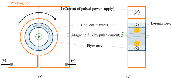
Figure 1.
Structure and operating elements of a tubular type actuator: (a) side view and (b) front view.
Figure 1.
Structure and operating elements of a tubular type actuator: (a) side view and (b) front view.
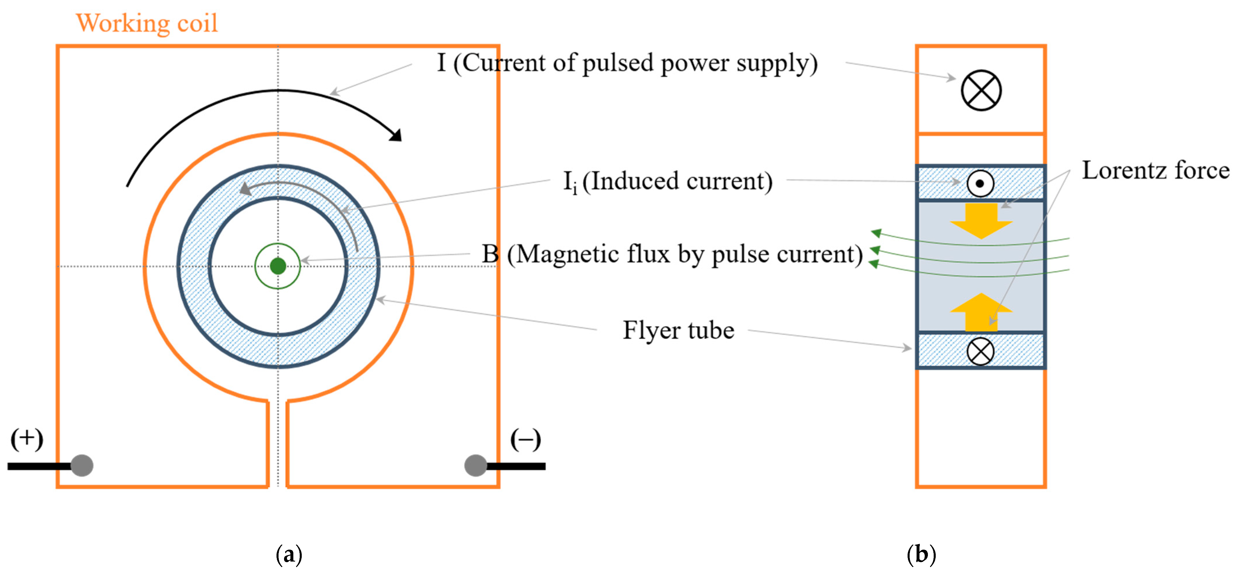
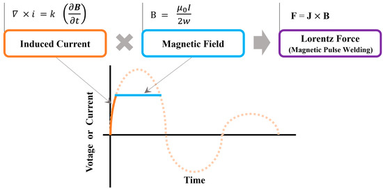
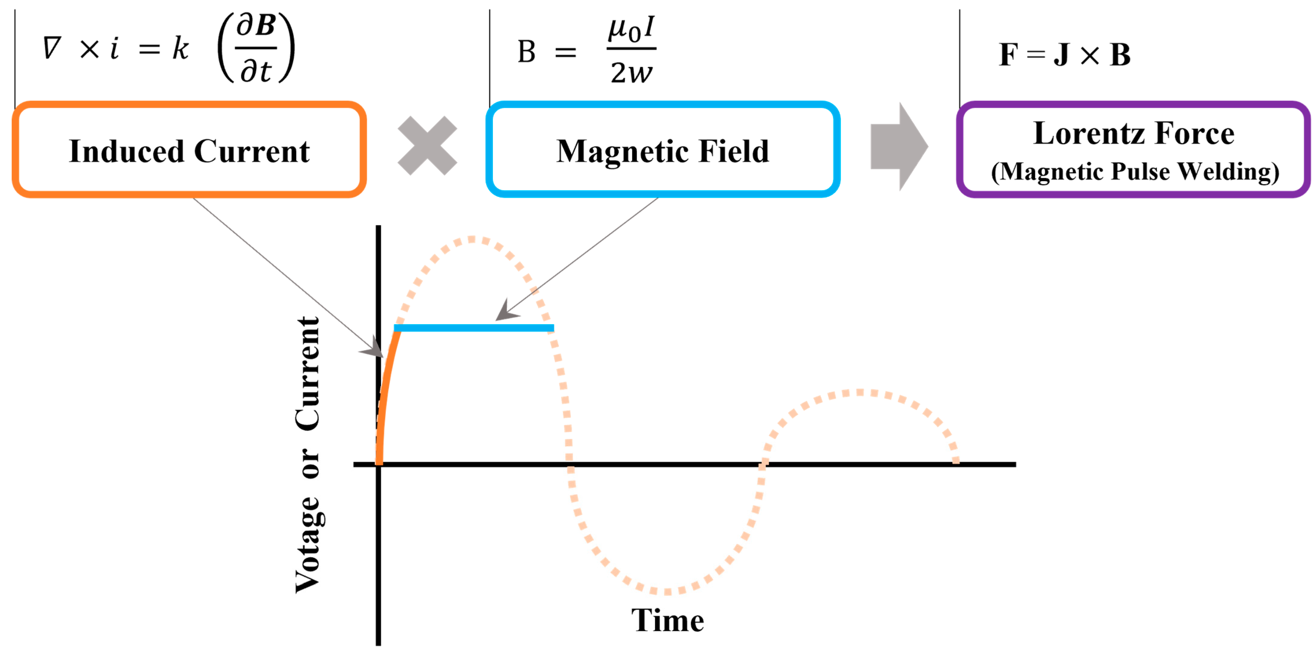
Figure 2.
Analysis of the relationship between the input waveform section and MPW operation.
Figure 2.
Analysis of the relationship between the input waveform section and MPW operation.
The frequency of the input power affects the area of the conductor through which current can flow, directing the current to the skin. This phenomenon is called the skin effect, which increases the resistance and decreases the current flowing through the actuator. The skin depth δ is shown as
where σ is the conductivity.
Second, the power supply has a pulse generator to generate large currents and discharges using a capacitor bank. The waveform of the power supplied to the actuator by this supply shows an underdamped oscillation waveform. Depending on the input waveform, the main factor affecting the above considerations is induced current. In Equation (3), the induced current is affected by the time-varying magnetic field, so the shape or rise time of the rising section of the input waveform has a significant influence. The magnitude of the external magnetic flux B in Equation (2) is determined by the current flowing in the MPW system. However, if the input waveform is an impulse or underdamped oscillation waveform, it is necessary to set a standard for the current that generates an effective external magnetic flux B. For impulse waveforms, the full width at half maximum (FWHM) is applied as 50% of the maximum current; for underdamped oscillation waveforms, 70% of the maximum current is applied. The factors affecting MPW operation and each section of the input waveform are summarized in Figure 2. In the rising section of the input waveform, the induced electromotive force is generated in the flyer tube due to the time change of magnetic flux, and magnetic flux is generated by the input current in the subsequent section. And Lorentz’s force is generated by the current and magnetic flux flowing through the flyer tube.
3. Input Pulse Waveform and Magnetic Pulse Welding Operation
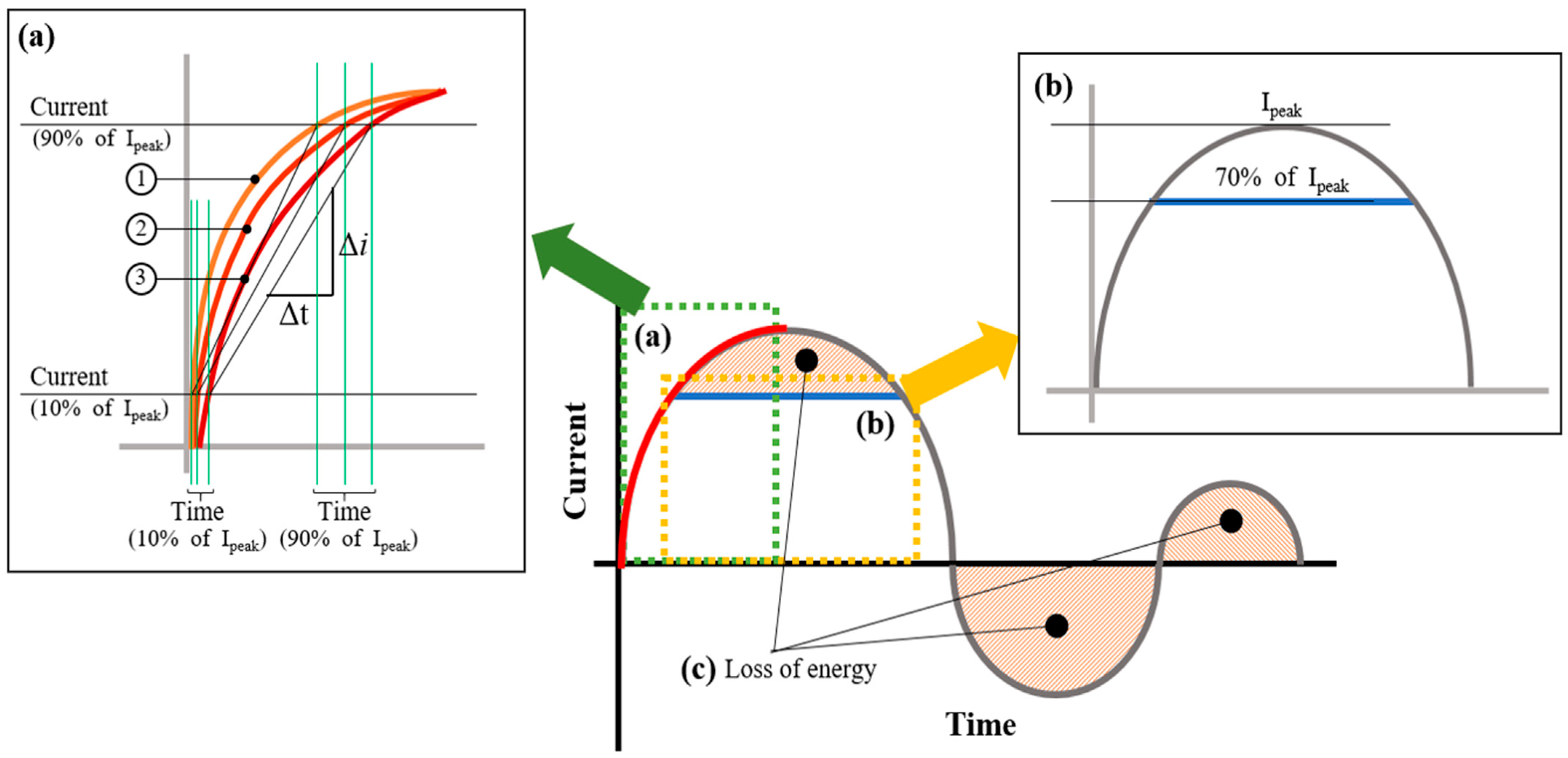
As shown in Equation (1), during MPW, the Lorentz force is affected by the magnitude of the current and magnetic flux. Among the factors that determine Lorentz force, the current density in the flyer tube is greatly influenced by the input current that determines the size of the external magnetic flux. Because the part that occupies most of the volume in the MPW system is the power supply, it is necessary to analyze the relationship between the shape of the input waveform of pulsed power and MPW operation to miniaturize the system and optimize the junction. Figure 3 shows the underdamped oscillation waveform, which is a representative input waveform of the MPW with the power supply type in Table 1, and a diagram of the elements of the MPW operation for each part of the waveform.
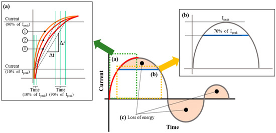
Figure 3.
Relationship between MPW operation and input waveform: (a) Δi/Δt graph, (b) direct current section and (c) loss of energy.
3.1. The Rising Part of the Input Waveform (Section (a) of Figure 3)—Induced Current (Ii)
Section (a) of Figure 3 is the rising section from the starting point of the input waveform that is underdamped oscillation. In the rising section, the magnitude of the current changes with respect to time; however, because the magnetic flux is proportional to the current, it can be regarded as a change in magnetic flux with respect to time in the rising section. Therefore, the magnitude of the induced current in the flyer tube varies depending on the rise time, as in Section (a) of Figure 3. The rise time is determined from the waveform using a slope of 10% and a peak current of 90%. As shown in Section (a) of Figure 3, the rise time increases from waveform ③ to ①, and the induced current similarly increases.
3.2. The Plateau Part of the Input Waveform (Section (b) of Figure 3)—External Magnetic Flux (B)
The plateau section of the input waveform generates an external magnetic flux. In the waveform shown in Figure 3, the magnitude that can be considered direct current is approximately 70% of the peak current. The sine waveform does not maintain a constant external magnetic flux. The changing magnetic flux causes a change in the magnitude of the Lorentz force, which prevents a constant force to the joint. As a result, the joint cannot be maintained consistently, which reduces reliability and complicates application.
In impulse waveforms, the theoretical magnitude of the current is not the same as the magnitude of the current’s effect on the MPW’s operation. Since it is difficult to determine the reference size, it is difficult to determine the optimal conditions through various experiments in each case. Therefore, rather than an underdamped or overdamped waveform, a plateau-shaped waveform with a clear maximum current magnitude is more reliable in the operation of the MPW and is more suitable for various applications.
3.3. The Hatched Area (Section (c) of Figure 3)—Energy Loss
The hatched part of Section (c) in Figure 3 is an area of energy that is not utilized in MPW operation and will be lost. The MPW is driven by the first half cycle of the input waveform. The oscillating region after the half-cycle when the maximum current flows becomes an ineffective region for MPW operation. By designing the pulse power to minimize the loss area, miniaturization and economical operation of the MPW system are possible. Therefore, the overdamped waveform or plateau waveform in the impulse waveform rather than the oscillated waveform is the most efficient power source form.
3.4. Proposed Waveform for Optimal MPW Operation
The Lorentz force, which affects MPW operation, is generated by the current flowing in a conductor (flyer tube) and the external magnetic field. In MPW, the induced current in the flyer tube and the external magnetic field generated by the same input power are simultaneously actuated. In the above analysis, the section of the input waveform that affects the induced current in the flyer tube is the rising section, where the current changes with time. The faster the rise time, the greater the change in the magnetic field with time; as a result, the magnitude of the induced current also increases.
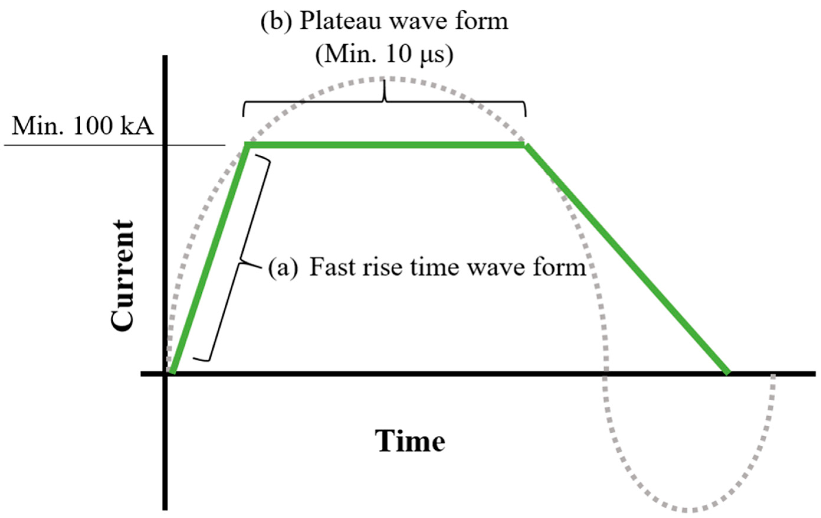
Because it is necessary to supply a constant current to maintain the external magnetic flux magnitude, a plateau waveform is better than a sine waveform. Because the section that affects MPW is the waveform up to the first half cycle, an overdamped or square pulse waveform is better than an underdamped waveform with oscillation. The waveform optimized with these findings is shown in Figure 4. As shown in the waveform in Figure 4, the rise time in the square pulse waveform is kept as short as possible, and the waveform is in the form of a plateau, which minimizes the losses in the MPW system operation and improves the reliability of the operation.
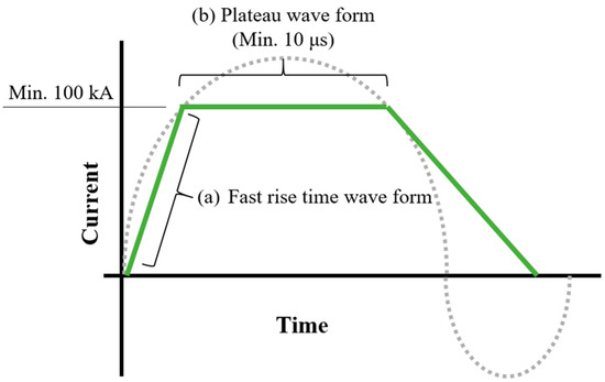
Figure 4.
Optimized waveform for MPW operation.
4. Design of the Optimal Pulsed Power System for Magnetic Pulse Welding
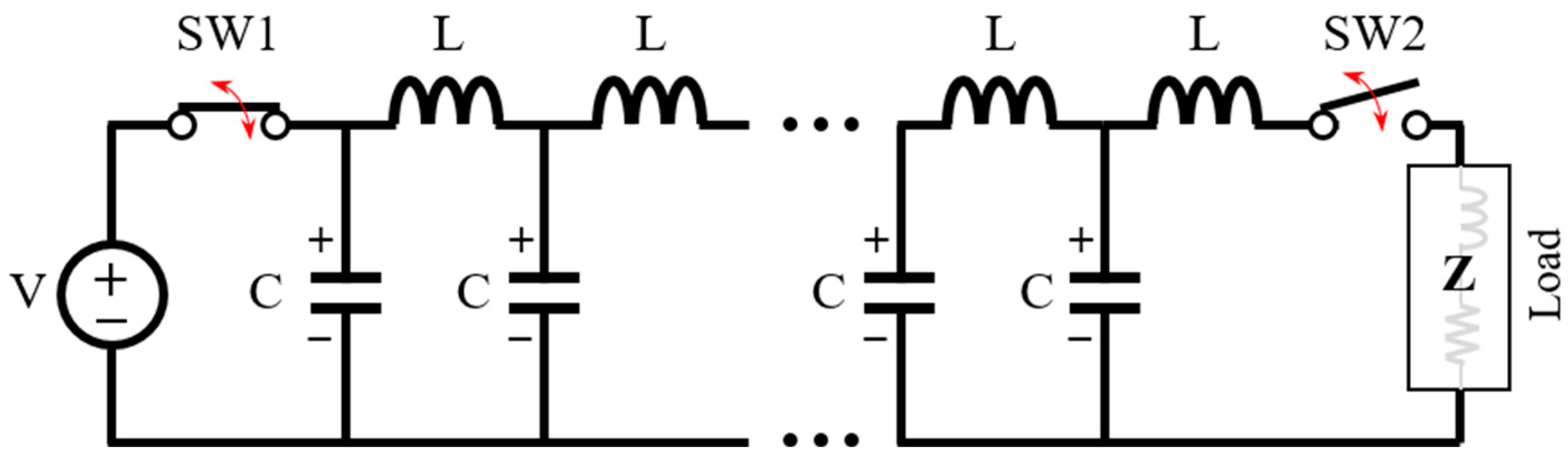
Based on the shape shown in Figure 4, the optimized waveform designed above, and the specifications of the existing MPW system, the waveform input to the actuator was analyzed as a square pulse waveform with a minimum current size of 100 (kA) and a pulse width of at least 10 (μs). A representative power device that generates high-power square pulses is the pulse-forming network (PFN). A representative circuit diagram of the PFN is shown in Figure 5. The operation of PFN can be explained in two stages. The first is to charge the capacitors of each stage, and charging is performed from the DC power source. Then, the switch 1 (SW1) maintains a closed state, and the switch 2 (SW2) maintains an open state. As a second step, after charging the capacitor is completed, the switch (SW1) becomes open, and the switch (SW2) becomes closed to supply power to the load. The energy charged in the capacitor is supplied to the load without loss only when the operations of SW1 and SW2 are performed at the same time. Therefore, the operation of the switch greatly affects the efficiency of the PFN and the reliability of the operation. In addition, although it represents a simple structure of L and C in design, it is greatly influenced by the parasitic components of the circuit. In particular, the size of the current is reduced due to the internal resistance value of the inductor and the parasitic resistance value in the circuit, or the plateau waveform cannot be maintained in the input waveform and appears in the form of an impulse. Therefore, a design to reduce internal resistance should be considered when designing PFN.
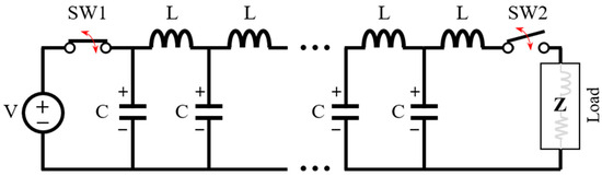
Figure 5.
Schematic of the pulse forming network (Type E).
The equation for determining the values of elements C and L in PFN design is as follows.
Here, C is the total capacitance [μF], L is the total circuit inductance [μH], T is the pulse width [μs], and Z is the circuit characteristic impedance [Ω] [24,25,26,27].
The design of circuit elements in a PFN is affected by the characteristic impedance of the load and the required pulse width. The structure of the actuator is shown in Figure 6. The actuator is made of a 5 (mm) thick copper plate with a width of 80 (mm) and a height of 90 (mm). The actuator has a plate structure and represents a 1-turn structure in the tubular type. Then, an insulator is installed to maintain the gap between the copper plate and the flyer tube. The measured impedance of the actuator is approximately 0.01 (Ω). The resistance and inductance values are approximately 0.01 (Ω) or less and approximately 0.1 (μH) or less, respectively. Based on this measurement, the total sums of the C values and L values of the PFN are calculated using Equations (6) and (7), respectively. The number of PFN stages is designed to be five, and the C and L of each stage are calculated. The design values for the PFN are summarized in Table 2.
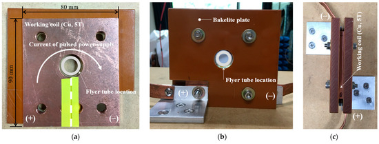
Figure 6.
Photos of the actuator: (a) structure, (b) front view, and (c) top view.
Table 2.
PFN specifications for the optimized pulsed power design.
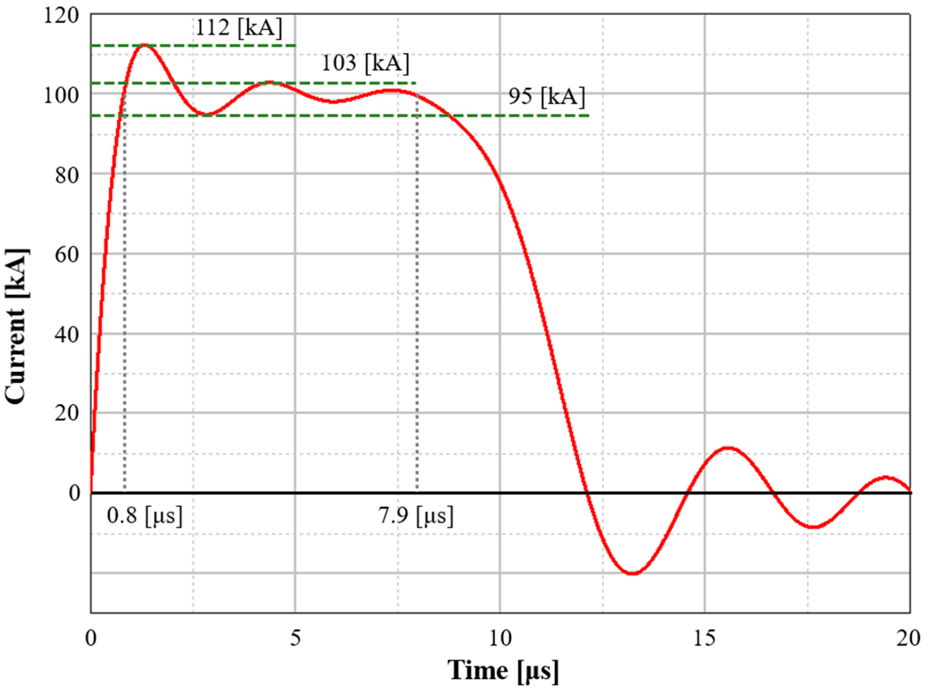
The model of PFN Type E was simulated using the design values in Table 2. The current output waveform for the simulation is shown in Figure 7. The current value of the output waveform in the plateau section, which forms the external magnetic field, is approximately 100 (kA). Considering this value as the same value as the effective value of the sine wave, the maximum value of the sine wave will be about 150 (kA).

Figure 7.
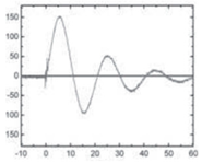
Current output waveform of the proposed pulsed power.
The force applied to conventional welding was comparable to the magnitude of the magnetic pressure; however, because the input power changes temporally, the current in the actuator powers the overall current via the induced electromotive force of the flyer tube. The current value is affected by the resistance of the flyer tube and the size of the induced electromotive force, which is related to the temporal change of the magnetic flux or the temporal change of the current. In Equation (2), I is the size of the current in the flyer tube and significantly influences the force affecting the joint. Therefore, the rise time of the current waveform is important.
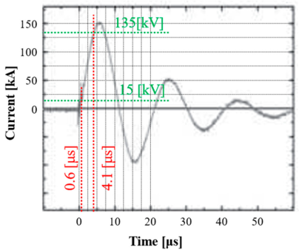
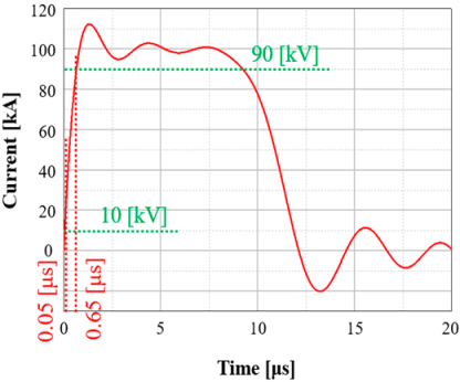
A comparison between a previously used pulsed power and the proposed pulsed power is presented in Table 3. In Equation (2), the size of the external magnetic flux (B) is related to the current value flowing in the actuator. Because the size of the current is similar in the existing and proposed models, the size of B can be considered the same. If the length of the conductor is the same, the Lorentz force is greatly affected by the size of the current in the flyer tube.
Table 3.
Output characteristics of the existing model vs. the proposed model.
Therefore, the rise time of the current waveform is analyzed because the magnitude of the electromotive force is proportional to the change in magnetic flux over time. The rise time for the existing pulsed power is 10% of the maximum current value of 150 (kA), and the rate of change (di/dt) for the 90% current value is 34. The current value and time for each can be confirmed in the waveform shown in Table 3. The rate of change in the rise time of the proposed model is 0.8 (μs) up to the maximum current value of 100 (kA), and the rate of change (di/dt) for current values of 90% and 10% of the maximum value is 133.
In comparison with the rise time, the size of the electromotive force induced in the flyer tube will be approximately 3.8 times that of the proposed model. If the impedance of the flyer tube is the same, the magnitude of the current is proportional to the size of the electromotive force, also with a difference of approximately 3.8 times.
Therefore, the proposed model shows a large Lorentz force even with less energy than the existing damped oscillation pulsed power. Using a pulsed power supply with this fast rise time and plateau waveform, it is possible to miniaturize the MPW system and improve economic feasibility by improving efficiency. In addition, as shown in Table 3, the economic operation of MPW is possible by driving the pulse power supply device of small energy.
5. Conclusions
An analysis of the effects of input power and MPW operation is required for the optimization of MPW operation or system. The existing MPW operation is analyzed using magnetic pressure, which is the Lorentz force of spatial change. The factor affecting the magnetic pressure is the magnitude of the input current, and the design of the pulse power source is also designed considering only the magnitude of the output current.
However, the form of input power of MPW is a waveform that changes over time, and there is a limit to the analysis of spatial changes, so it is necessary to analyze the temporal change of the input waveform. In this paper, the relationship between the Lorentz force that affects MPW according to the input waveform that changes over time is analyzed, and a model for the optimal input waveform is presented. The following summarizes the analysis of the relationship between the induced current and external magnetic flux of the fly tube for input current in the operation of MPW.
- Because the induced electromotive force is proportional to the time change of the current, the rise time of the current must be fast.
- The external magnetic flux is proportional to the size of the current, so a constant current must flow to maintain a constant external magnetic flux.
Based on the above analysis, the optimal input waveform has a fast rise time and is plateau-shaped. To implement this input waveform, a PFN design, a type of pulsed power device, was used. The design specification of the optimal power supply was created by combining existing papers to design a PFN power supply capable of outputting a maximum input current of 150 (kA) (RMS. 100 (kA)) and a pulse width of 10 (μs). The output waveform was confirmed through simulation to have a maximum current of 100 kA, rise time of 0.8 (μs), pulse width of 12 (μs), and plateau section width of 7.2 (μs). The optimal power source not only reduced the amount of energy compared with the existing power source but also increased the size of the Lorentz force of MPW with a fast rise time. In addition, the reliability of the MPW operation increased by maintaining a constant external magnetic flux due to the plateau current. Therefore, it is expected that MPW can be applied to various industrial fields as its miniaturization, economical operation, and reliability increase.
Author Contributions
Conceptualization, Y.-M.K.; Writing—original draft, Y.-M.K. and M.-W.H.; Writing—review & editing, K.-C.K.; Supervision, K.-C.K. All authors have read and agreed to the published version of the manuscript.
Funding
This research received no external funding.
Data Availability Statement
Data are contained within the article.
Conflicts of Interest
The authors declare no conflict of interest.
References
- Murr, L.E.; Gaytan, S.M.; Ramirez, D.A.; Martinez, E.; Hernadez, J.; Amato, K.N.; Shindo, P.W.; Medina, F.R.; Wicker, F.B. Metal fabrication by additive manufacturing using laser and electron beam melting technologies. J. Mater. Sci. Technol. 2012, 28, 1–14. [Google Scholar] [CrossRef]
- Heidarzadeh, A.; Mironov, S.; Kaibyshev, R.; Cam, G.; Simar, A.; Gerlich, A.; Khodabakhshi, F.; Mostafaei, A.; Field, D.P.; Robson, J.D.; et al. Friction stir welding/processing of metals and alloys: A comprehensive review on microstructural evolution. Prog. Mater. Sci. 2021, 117, 100752. [Google Scholar] [CrossRef]
- Wang, B.; Yang, F.; Zhang, H.; He, P. Interfacial microstructure and mechanical properties of AZ31B/AA7075 joints using non-equilibrium thermal compensation resistance welding. J. Mater. Res. Technol. 2023, 24, 2946–2951. [Google Scholar] [CrossRef]
- Zhang, J.; Chen, S.; Zhao, H.; Yu, Y.; Liu, M. Designing a Multi-Output Power Supply for Multi-Electrode Arc Welding. Electronics 2023, 12, 1702. [Google Scholar] [CrossRef]
- Hahn, M.; Weddeling, C.; Lueg-Althoff, J.; Tekkaya, A.E. Analytical approach for magnetic pulse welding of sheet connections. J. Mater. Process. Technol. 2016, 230, 131–142. [Google Scholar] [CrossRef]
- Pereira, D.; Oliveira, J.P.; Pardal, T.; Miranda, R.M.; Santos, T.G. Magnetic pulse welding: Machine optimization for aluminium tubular joints production. Sci. Technol. Weld. Join. 2018, 23, 172–179. [Google Scholar] [CrossRef]
- Yao, Y.; Chen, A.; Wang, D.; Wang, S.; Jiang, H.; Li, G.; Cui, J. Fatigue behavior of Al-CFRP spot-welded joints prepared by electromagnetic pulse welding. Int. J. Fatigue 2023, 174, 107715. [Google Scholar] [CrossRef]
- Li, Z.; Peng, W.; Chen, Y.; Liu, W.; Zhang, H. Simulation and experimental analysis of Al/Ti plate magnetic pulse welding based on multi-seams coil. J. Manuf. Proces. 2022, 83, 290–299. [Google Scholar] [CrossRef]
- Yao, Y.; Jing, L.; Wang, S.; Li, G.; Cui, J.; Tang, X. Mechanical properties and joining mechanisms of Al-Fe magnetic pulse welding by spot form for automotive application. J. Manuf. Process. 2022, 76, 504–517. [Google Scholar] [CrossRef]
- Ben-Artzy, A.; Stern, A.; Frage, N.; Shribman, V.; Sadot, O. Waveformation mechanism in magnetic pulse welding. Int. J. Impact Eng. 2010, 37, 397–404. [Google Scholar] [CrossRef]
- Zhang, W.; Chen, Y.; Xie, J.; Zhang, T.; Wang, S.; Song, X.; Yin, L. Interfacial microstructure of Al/Ta dissimilar joints by magnetic pulse welding. J. Mater. Res. Technol.-JMRT 2023, 23, 4167–4172. [Google Scholar] [CrossRef]
- Shotri, R.; Faes, K.; Racineux, G.; De, A. Analytical Estimation of Electromagnetic Pressure, Flyer Impact Velocity, and Welded Joint Length in Magnetic Pulse Welding. Metals 2022, 12, 276. [Google Scholar] [CrossRef]
- Shortri, R.; Faes, K.; Racineux, G.; De, A. Improved Coil Design for Magnetic Pulse Welding of Metallic Sheets. J. Manuf. Mater. Process. 2022, 6, 144. [Google Scholar]
- Shortri, R.; Racineux, G.; De, A. Magnetic pulse welding of metallic tubes—Experimental investigation and numerical modeling. Sci. Technol. Weld. Join. 2020, 25, 273–281. [Google Scholar] [CrossRef]
- Strizhakov, E.L.; Nescoromniy, S.V.; Inasaridze, G.I.; Stroganov, A.N. Magnetic-pulse of assembly of details one-piece compositions. IOP Conf. Ser. Mater. Sci. Eng. 2021, 1029, 012065. [Google Scholar] [CrossRef]
- Song, J.W.; Park, J.J.; Lee, G.J.; Lee, M.K.; Park, K.H.; Hong, S.J.; Lee, J.G. Effect of Impact Velocity on Interface Characteristics of HT-9 Steel Joints Fabricated by Magnetic Pulse Welding. Met. Mater. Int. 2020, 26, 360–369. [Google Scholar] [CrossRef]
- Mishra, S.; Sharma, S.K.; Kumar, S.; Sagar, K.; Meena, M.; Shyam, A. 40 kJ magnetic pulse welding system for expansion welding of aluminium 6061 tube. J. Mater. Process. Technol. 2017, 240, 168–175. [Google Scholar] [CrossRef]
- Drehmann, R.; Scheffler, C.; Winter, S.; Psyk, V.; Krausel, V.; Lampke, T. Experimental and Numerical Investigations into Magnetic Pulse Welding of Aluminum Alloy 6016 to Hardened Steel 22MnB5. J. Manuf. Mater. Process. 2021, 5, 66. [Google Scholar] [CrossRef]
- Li, Z.; Peng, W.; Chen, Y.; Liu, W.; Zhang, H. Analysis of energy transfer process in magnetic pulse welding and optimization of system efficiency. Int. J. Adv. Manuf. Technol. 2023, 125, 2425–2434. [Google Scholar] [CrossRef]
- Aizawa, T.; Kashani, M.; Okagawa, K. Application of Magnetic Pulse Welding for Aluminum Alloys and SPCC Steel Sheet Joints. Weld. J. 2007, 86, 119–124. [Google Scholar]
- Kore, S.D.; Date, P.P.; Kulkarni, S.V. Effect of process parameters on electromagnetic impact welding of aluminum sheets. Int. J. Impact Eng. 2007, 34, 1327–1341. [Google Scholar] [CrossRef]
- Aizawa, T. Magnetic pressure seam welding method for aluminium sheets. Weld. Int. 2003, 17, 929–933. [Google Scholar] [CrossRef]
- Aizawa, T. Magnetic Pulse Welding of Sheet Metals using Flat Three-Turn Coil. In Proceedings of the International Workshop on Explosion, Shock-Wave and High-Velocity Phenomena, Kumamoto, Japan, 28–29 September 2015; pp. 25–28. [Google Scholar]
- Musolino, A.; Raugi, M.; Tellini, B. Pulse Forming Network Optimal Design for the Power Supply of Eml Launchers. IEEE Trans. Magn. 1997, 33, 480–483. [Google Scholar] [CrossRef]
- Rathod, P.J.; Anitha, V.P.; Sholapurwala, Z.H.; Saxena, Y.C. A Guillemin type E pulse forming network as the driver for a pulsed, high density plasma source. Rev. Sci. Instrum. 2014, 85, 063503. [Google Scholar] [CrossRef]
- Ma, X.; Yu, Z.; Xiao, J.; Xu, F.; Ding, M.; Lin, W.; Peng, E.; Li, H. Development of a pulsed power supply with tens of milliseconds flattop time. Rev. Sci. Instrum. 2020, 91, 034707. [Google Scholar] [CrossRef]
- Zhang, H.; Shu, T.; Liu, S.; Zhang, Z.; Song, L.; Zhang, H. A Compact Modular 5 GW Pulse PFN-Marx Generator for Driving HPM Source. Electronics 2021, 10, 545. [Google Scholar] [CrossRef]

Disclaimer/Publisher’s Note: The statements, opinions and data contained in all publications are solely those of the individual author(s) and contributor(s) and not of MDPI and/or the editor(s). MDPI and/or the editor(s) disclaim responsibility for any injury to people or property resulting from any ideas, methods, instructions or products referred to in the content. |
© 2023 by the authors. Licensee MDPI, Basel, Switzerland. This article is an open access article distributed under the terms and conditions of the Creative Commons Attribution (CC BY) license (https://creativecommons.org/licenses/by/4.0/).