Article

Study of Single-Event Effects Influenced by Displacement Damage Effects under Proton Irradiation in Static Random-Access Memory

1
College of Electrical, Energy and Power Engineering, Yangzhou University, Yangzhou 225127, China
2
Innovation Center for Radiation Application, Beijing 102413, China
3
Innovation Academy for Microsatellites of Chinese Academy of Sciences, Shanghai 201203, China
4
China Academy of Space Technology, Beijing 100029, China
5
Institute of Special Environments Physical Sciences, Harbin Institute of Technology, Shenzhen 518055, China
*
Authors to whom correspondence should be addressed.
Electronics 2023, 12(24), 5028; https://doi.org/10.3390/electronics12245028
Submission received: 30 October 2023 / Revised: 9 December 2023 / Accepted: 14 December 2023 / Published: 16 December 2023
(This article belongs to the Section Microelectronics)

Abstract

:
Static random-access memory (SRAM), a pivotal component in integrated circuits, finds extensive applications and remains a focal point in the global research on single-event effects (SEEs). Prolonged exposure to irradiation, particularly the displacement damage effect (DD) induced by high-energy protons, poses a substantial threat to the performance of electronic devices. Additionally, the impact of proton displacement damage effects on the performance of a six-transistor SRAM with an asymmetric structure is not well understood. In this paper, we conducted an analysis of the impact and regularities of DD on the upset cross-sections of SRAM and simulated the single-event upset (SEU) characteristics of SRAM using the Monte Carlo method. The research findings reveal an overall increasing trend in upset cross-sections with the augmentation of proton energy. Notably, the effect of proton irradiation on the SEU cross-section is related to the storage state of SRAM. Due to the asymmetry in the distribution of sensitive regions during the storage of “0” and “1”, the impact of DD in the two initial states is not uniform. These findings can be used to identify the causes of SEU in memory devices.

1. Introduction

The dosage of particle radiation in the space environment accumulates gradually. During the operational phase of spacecraft in space, there is an accumulation of high-energy proton irradiation, leading to a concurrent impact of various radiation effects, such as SEE and total ionizing dose (TID) effects. This combined action has unpredictable implications for the reliability and operational lifespan of spacecraft [1,2,3,4,5]. Static random-access memory (SRAM), typically structured as a cross-coupled flip flop with six CMOS devices, is extensively utilized in various aerospace applications. To date, the research on SRAM’s combined effects has mainly focused on the influence of TID effects on the SEU cross-section of SRAM [6,7,8,9,10,11].
Some findings suggest that the pre-irradiation total ionizing dose leads to an increasing trend in the SEU cross-section of six-transistor SRAM [12]. Additionally, there is evidence indicating “imprinting effects” in SRAM, wherein the sensitivity to SEE exhibits a certain dependence on stored data patterns [13].
While extensive research has been conducted globally on the SEE of memory devices, the majority has concentrated on the impact of heavy ions. Protons, being a primary component in the space radiation environment with high abundance and a broad energy range, have gradually become a focal point of radiation effect research [14,15,16,17,18].
While MOS devices are more sensitive to TID, the energy deposition from displacement damage under high-energy proton cumulative irradiation should not be overlooked. With the continuous developments in space technology, an increasing number of electronic devices have been applied in the space radiation environment. The DD caused by high-energy protons in the space environment will significantly impair the performance of electronic devices [19,20]. Therefore, studying the impact of displacement damage effects on proton single-event effects in SRAM is of crucial significance for evaluating the radiation resistance of electronic devices [21].
The SRAM chip utilized in the experiment is designed for configuring FPGA circuits. This device employs an asymmetric structure with the aim of enhancing the performance of power-on and configuration in FPGA circuits. However, the impact of proton displacement damage effects on the performance of SRAM with this asymmetrical structure is not clearly understood. In this study, we conducted research on how the displacement damage influenced SEU sensitivity in SRAM irradiated by protons. And we found that proton cumulative irradiation has different effects on the flip sensitivity of different storage states. The underlying mechanism was revealed to be that the proton-induced displacement damage had a greater effect on state “0”, resulting in a larger SEU sensitive region for the state “0”. This research provides technical support for evaluating single-event effects in memory devices in high-dose proton irradiation environments.

2. Experimental Setup

The proton irradiation experiment was conducted using the high-intensity proton accelerator of the China Spallation Neutron Source. The schematic diagram of the experimental setup is shown in Figure 1. Protons generated by the accelerator undergo appropriate focusing and acceleration before irradiating the test samples. The experimental samples, powered by a DC power supply, are monitored in real time for changes in device power consumption. The spot size of the proton beam was set at 30 mm × 30 mm, and flux was 3.15 × 10⁷~2.15 × 10⁸ p/cm2/s for 20~60 MeV protons.
The experimental samples selected were domestically produced JM7164L30 8 K × 8-bit low-power asynchronous timing SRAM. Two samples, labeled as #1 and #2, were employed in the experiment and packaged in flat dual inline package (FDIP) format. The internal chip size of SRAM is 3 mm × 3 mm. Both samples share characteristic process dimensions of 500 nm, have a capacity of 8 K × 8 bits, and operate at a voltage of 4.5 V. The devices used in this experiment are asymmetrically structured 6T SRAM storage cells (the unit structure is illustrated in Figure 2). The two inverters responsible for implementing the latch function employ different sizes, specifically different width-to-length ratios. The specific dimensional details are as follows: NMOS (N1), 1.6 µm/0.5 µm; NMOS (N2), 1.2 µm/0.5 µm; PMOS (P1), 1.2 µm/0.5 µm; and PMOS (P2), 1.6 µm/0.24 µm. In Figure 2, for the storage state “1”, the storage node IN = “1”, and the storage node OUT = “0”; for the storage state “0”, the storage node IN = “0”, and the storage node OUT = “1”. During the experiment, we control the storage state by inputting different data. In the simulation, we control the storage state by defining the data of the IN and OUT nodes.
Our experiment consisted of two steps. In the first step, proton displacement damage irradiation was performed on SRAM #2. Without applying power, we selected an energy value of 80 MeV, with an accumulated fluence of 1 × 10¹⁴ p/cm2, and protons were vertically incident on the device, completely covering the entire chip. In the second step, proton single-event upset experiments were conducted on SRAM #1 and SRAM #2. The irradiation voltage was set at 4.5 V. We selected three energy values: 20 MeV, 40 MeV, and 60 MeV (the specific beam information is detailed in Table 1). For each energy value, protons were vertically incident on the devices SRAM #1 and SRAM #2. The experimental investigation aimed to explore the impact of proton cumulative irradiation and energy on SEU sensitivity in SRAM devices.

3. Experimental Results

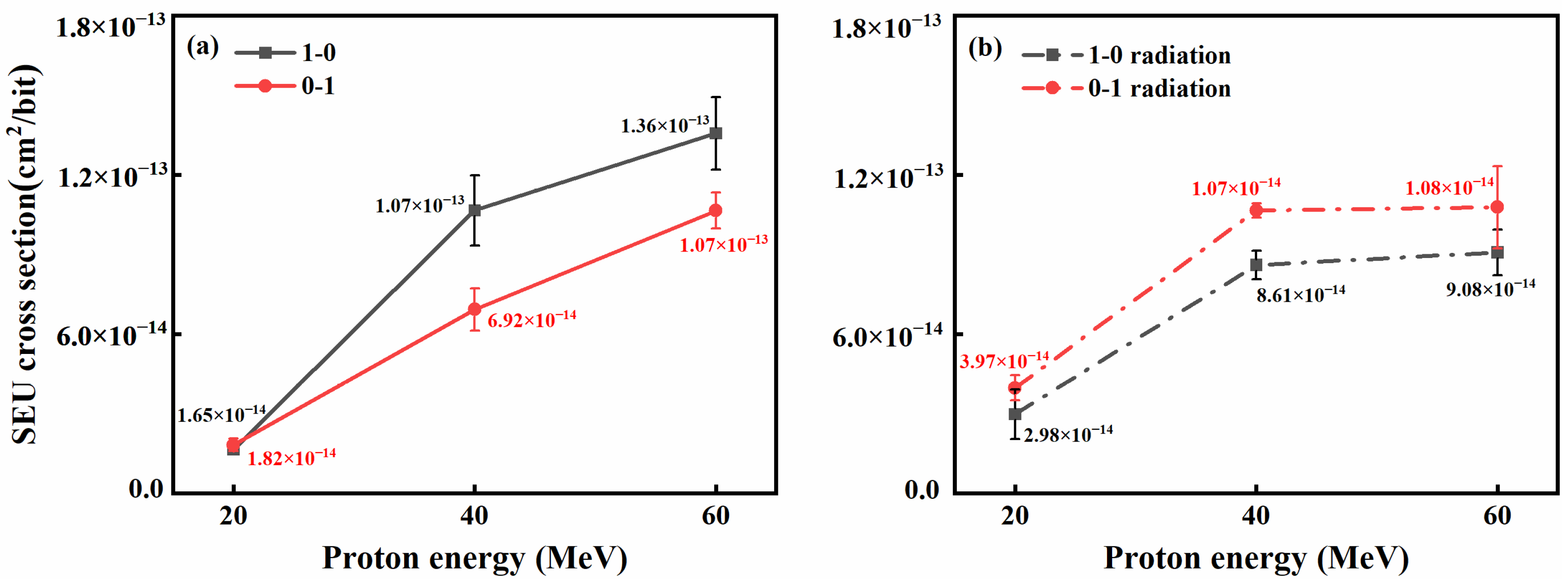
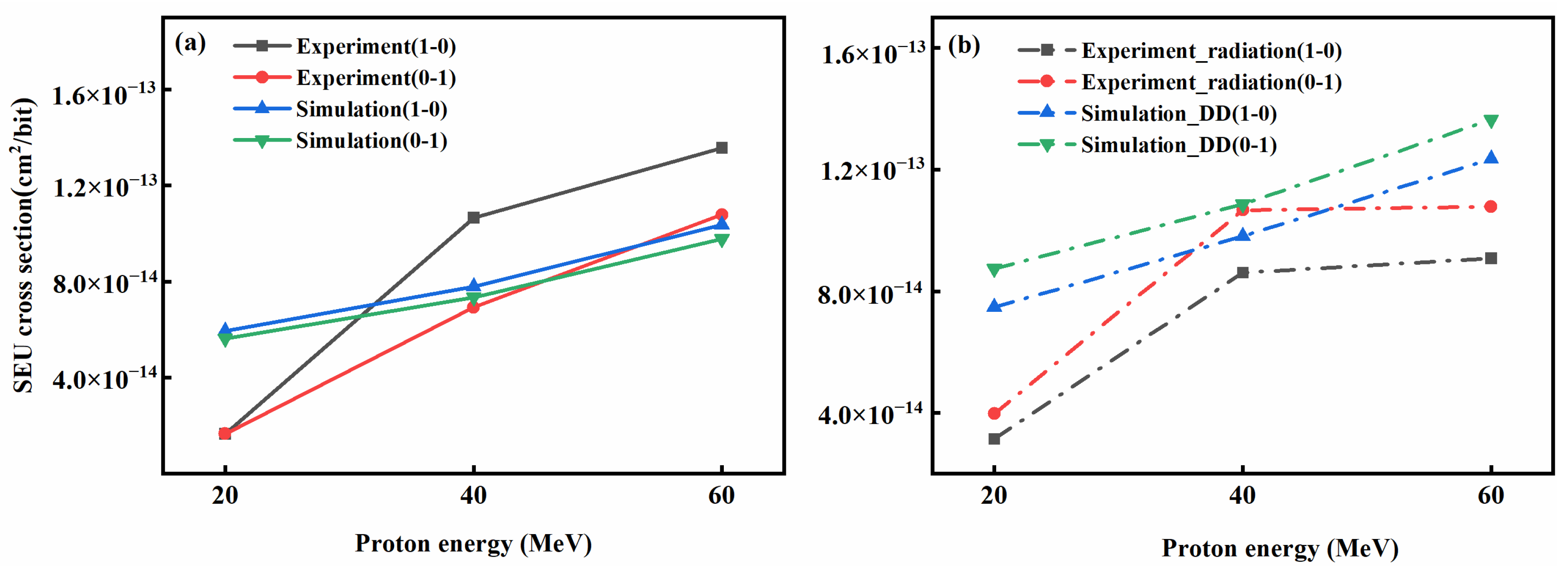
High-energy proton irradiation tests were conducted in static test mode, and the experimental results are depicted in Figure 3a,b. The statistical results of SRAM upset counts are as shown in Table 2. Figure 3 displays the upset cross-sections corresponding to different initial storage states for the two SRAM devices under 20, 40, and 60 MeV proton irradiation. In the figure, “0-1” indicates that the storage status changes from 0 to 1, and “1-0” indicates that the storage status changes from 1 to 0.
The experimental findings depicted in Figure 3 lead to three conclusions. Firstly, by comparing the results of experiments with different initial states, we observe variations in the upset cross-sections, indicating that the SEU cross-section of the device during proton irradiation testing is influenced by its initial state. Secondly, through comparing results under different proton energy conditions, a general trend emerges whereby the SEU cross-section increases with the rise in proton energy. Thirdly, comparing results with or without prior proton cumulative irradiation, we observe that SRAM devices pre-irradiated with protons consistently exhibit an SEU cross-section for “0” greater than that for “1”. In other words, it is easier for SRAM devices to flip from “0” to “1” after being pre-irradiated with protons, which is contrary to the results observed in SRAM devices without proton irradiation. A more in-depth analysis of these experimental results will be discussed in subsequent sections.

4. Results and Discussion

4.1. Monte Carlo Simulation and Modeling

Furthermore, we used theoretical simulation to analyze the damage mechanism of the device after proton irradiation to explain the experimental findings. For the proton single-event upset experimental results on sub-micrometer feature-size bulk silicon process SRAM devices, we conducted further simulated research on proton single-event upsets. We utilized Geant4 simulation to model the physical parameters of high-energy proton interactions in the sensitive region, obtaining key parameters such as the linear energy transfer (LET) and the relationship between secondary nuclear reactions and the wiring layer structure concerning single-event effects.
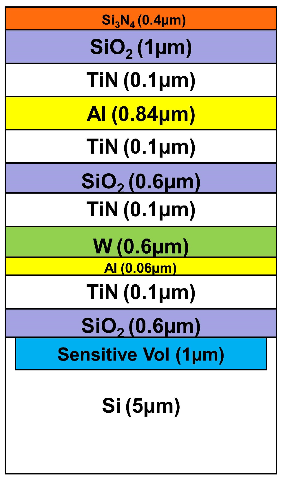
The SRAM device used in the simulation had multiple metal layers. To simulate the environment of proton incidence on the device, the simulated device structure and material profile are illustrated in Figure 4, with overall dimensions of 10 µm × 10 µm × 10.4 µm. The dashed region represents the sensitive area, measuring 1 µm × 10 µm × 10 µm. The simulation involved 108 protons vertically incident on the entire device, with specific energies of 20, 40, 60, and 80 MeV. Protons incident in the sensitive region deposited energy within that area.
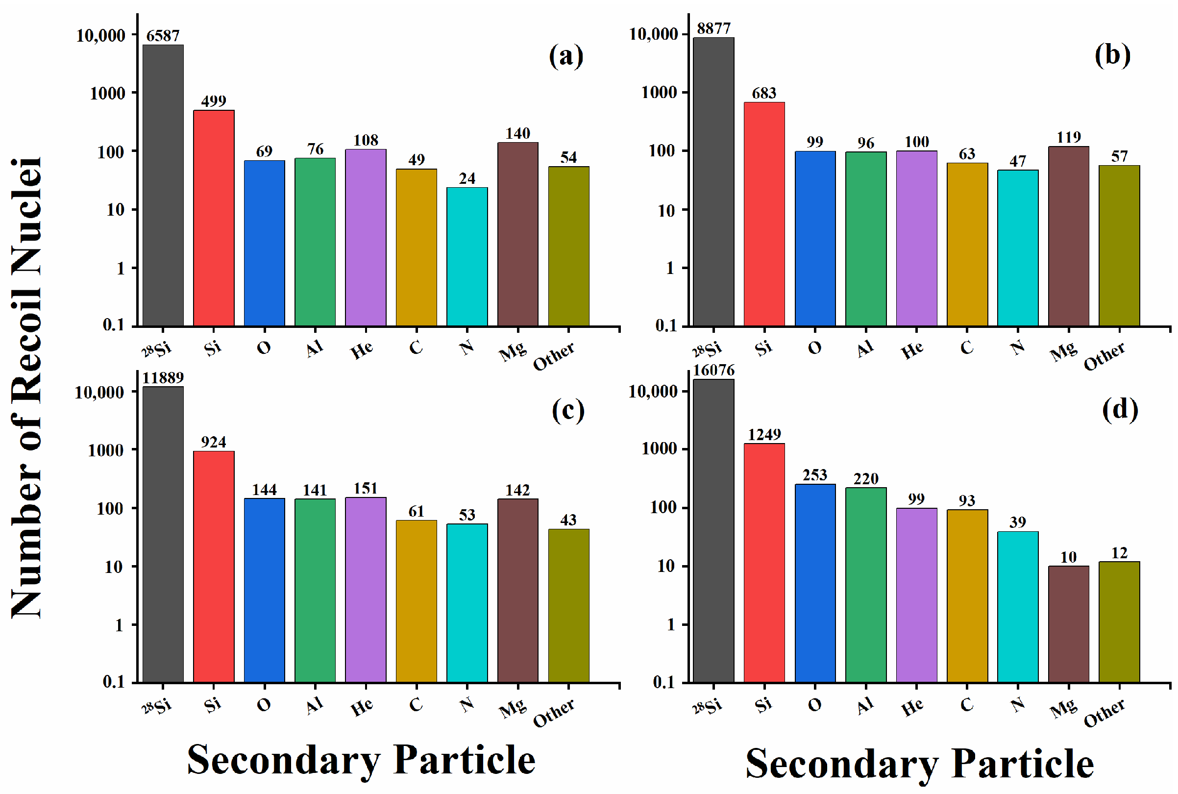
As shown in Figure 5, a significant number of recoil nuclei, including 28Si resulting from elastic collisions and particles such as Si, O, and Al produced through nuclear reactions, are generated due to the interaction between space high-energy particles and the device wiring layers. It can be observed from Figure 5 that high-Z recoil nuclei like Si, Al, Mg, Na, and Ne constitute the majority of the nuclear reaction products. Since the predominant material in the device is Si, the likelihood of high-energy particles interacting with Si is higher, leading to a greater occurrence of cascade reactions with Si. The yield of recoil nuclei generated via the interaction of space high-energy protons with CMOS process devices tends to increase with the energy of incident particles, which agrees with previous findings [22,23].
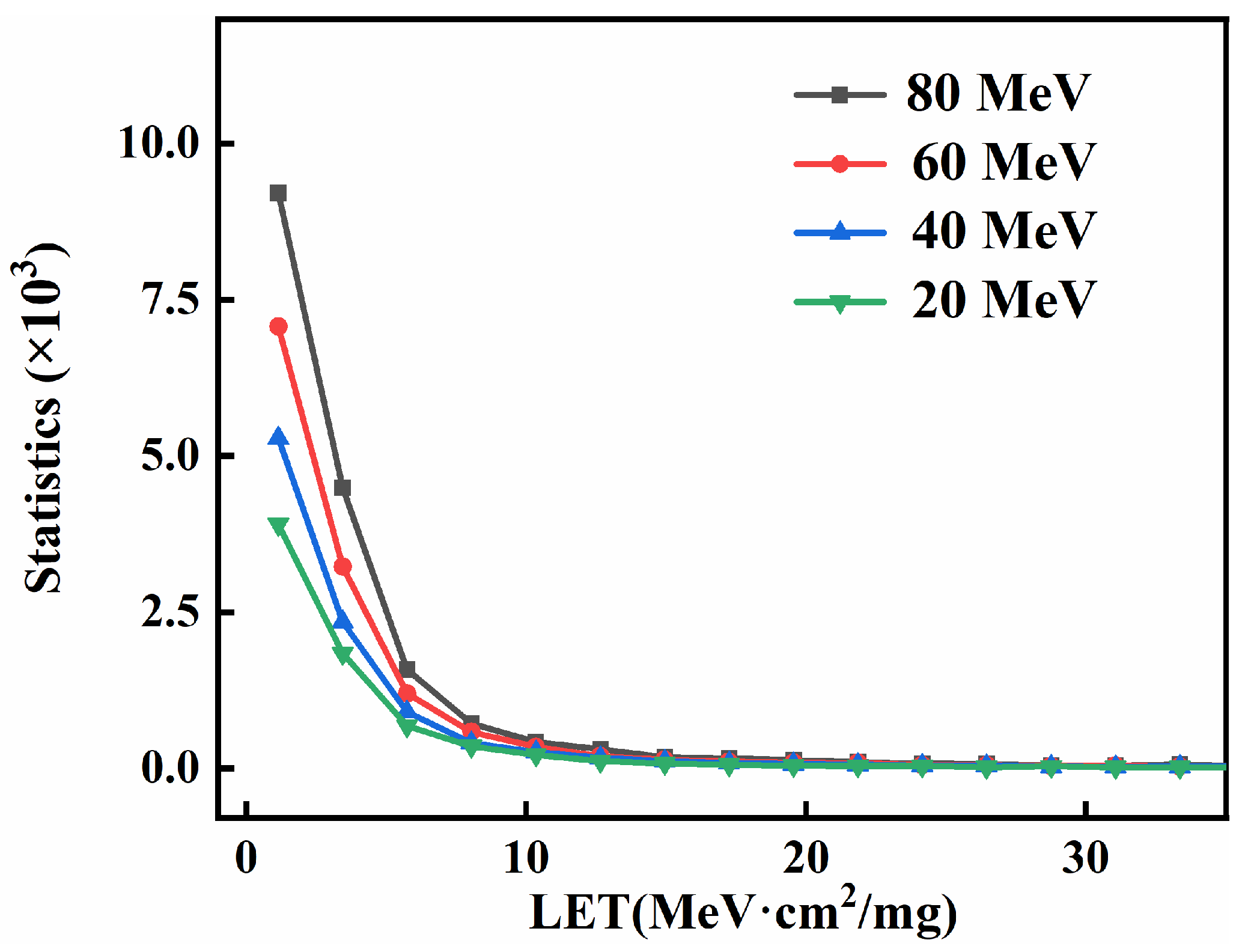
Typically, higher-energy protons can induce SEE through the indirect ionization process, where protons undergo nuclear reactions with atoms in the material. This process generates secondary heavy ion fragments with high linear energy transfer (LET) values. These high-LET secondary particles can, in turn, cause SEE through the direct ionization process [24]. As depicted in Figure 6, the LET values of secondary particles generated through proton incidence in semiconductor devices are primarily distributed within the range from 0 to 25 MeV·cm2/mg. With an increase in the incident proton energy, the number of secondary particles with LET values in the range from 0 to 10 MeV·cm2/mg also increases. The deposited energy in the sensitive region of the device also rises, making it more prone to triggering SEU in the memory.
For the pre-irradiated SRAM #2 device with proton cumulative irradiation, as the device is not powered at this point, and there is no external electric field, the electrons generated through radiation cannot be swept out of the oxide layer, and ionization energy cannot be deposited. Therefore, the TID is considered relatively weak, with the main focus being on the impact of displacement damage on the SRAM device. Non-ionizing energy deposition of protons in silicon arises partly from the Coulomb interaction of protons with the target, i.e., the electromagnetic interaction portion, and partly from the energy deposited through the proton-nuclear reaction [25]. Under the irradiation conditions of 80 MeV energy and 1 × 10¹⁴ p/cm2, the non-ionizing energy deposition from proton cumulative irradiation is 8.04 × 10⁻³ MeV through Geant4 simulation.

4.2. TCAD and SPICE Simulation

For this section, we employed a comprehensive approach using the device simulation software TCAD (Extreme-environment Radiation Effect Technology Computer Aided Design) combined with the circuit simulation software SPICE. Initially, we utilized TCAD to simulate the DD on the device characteristics and extracted the SPICE model parameters. Subsequently, through SPICE, we conducted circuit simulations to obtain the LET threshold for device flipping and calculated the SRAM upset cross-sections, laying the groundwork for further interpreting experimental phenomena.
The specific operational steps involved incorporating the beam information from the displacement damage experiments in Section 2 and the numerical values calculated in Section 4.1 using Geant4 into the simulation conditions of TCAD for displacement damage. We defined the particle type, initial irradiation flux, and particle irradiation energy, taking into account the particle damage factor, non-ionizing energy loss in materials, and defect distribution.
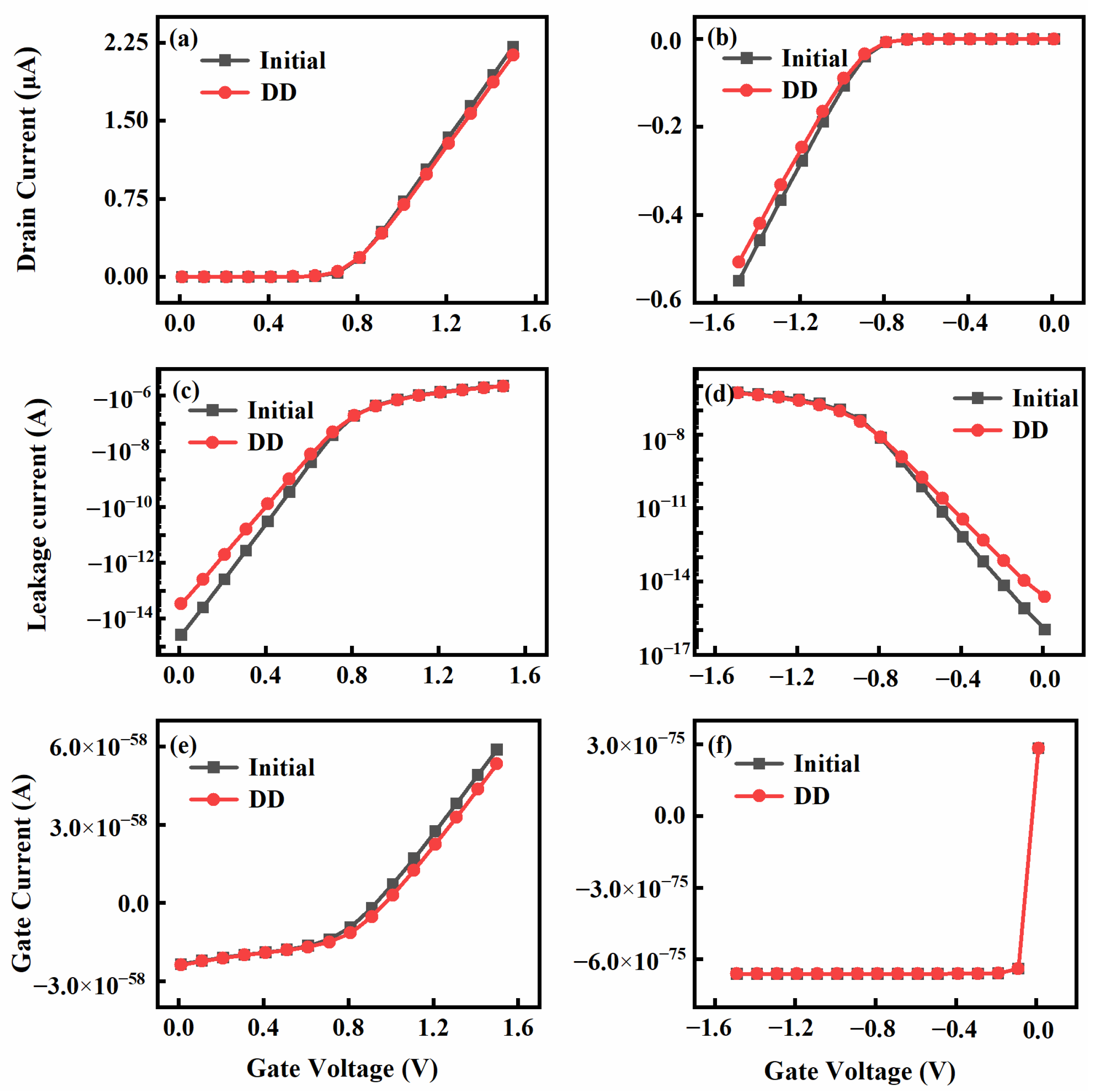
The MOS device process parameters used in our simulations are shown in Table 3. The final results are presented in Figure 7, illustrating the changes in the electrical performance of the device before and after displacement damage. Through Figure 7, we can observe that before and after irradiation, the gate current is very small, almost negligible. This phenomenon indicates that, under a proton accumulated dose of 1 × 10¹⁴ p/cm2, the gate oxide layer of the device remains intact. From the figure, it can be observed that the NMOS transfer characteristics shift to the right, indicating an increase in threshold voltage when the opening voltage is applied, and the subthreshold current increases when the device is not opened. In contrast, for PMOS, the transfer characteristics shift negatively when the opening voltage is applied, with an increase in the absolute value of the threshold voltage and, simultaneously, the subthreshold current increases when the device is not opened.
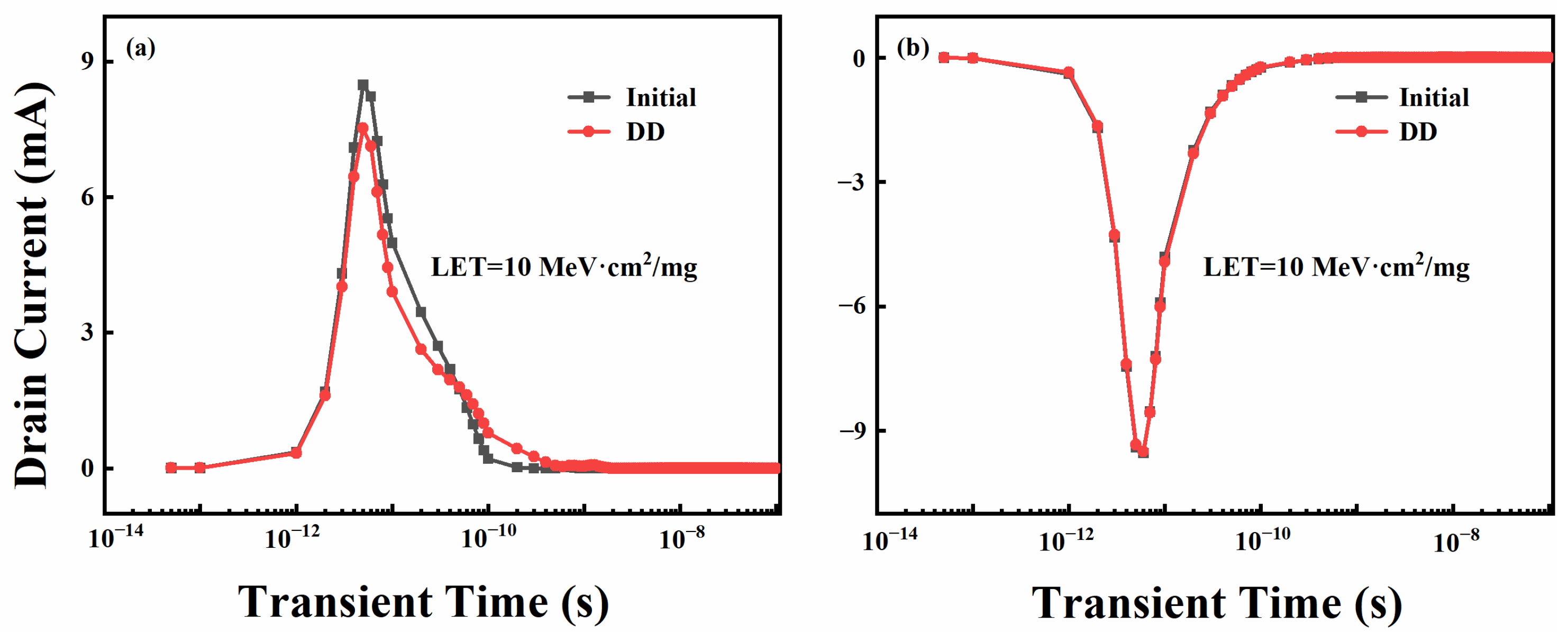
To investigate the impact of displacement damage radiation on SEE, we incorporated an SEE simulation module into the displacement damage model constructed above for a coupled simulation. This allowed us to analyze the characteristics of SEE in devices subjected to displacement damage effects. As shown in Figure 8, the transient drain current values corresponding to LET = 10 MeV·cm2/mg with or without irradiation are depicted. It is evident from Figure 8 that, with the introduction of displacement damage defects, there is a noticeable decrease in the peak transient drain current for NMOS, while the peak transient drain current for PMOS shows minimal variation.
We injected transient currents obtained at different LET values into the SRAM circuit, and determined the critical LET value based on the flipping condition of the SRAM. Subsequently, using the LET spectrum distribution graph calculated using Geant4, as illustrated in Figure 6, we obtained the number N of secondary particles with LET values exceeding the device’s LET threshold. Further calculations were conducted to derive the single-event upset cross-section (σ), as shown in Formula (1):
σ = N ϕ × M
In the equation, ϕ represents the fluence, which is the total number of protons incident on the device per unit area (cm2), with units of protons p/cm2. M represents the number of bits in the memory. When the simulation is carried out, the molecular N needs to be multiplied by the factor K, which is the ratio of the actual area of the device to the simulation. The cross-section (σ) denotes the sensitivity of the tested device to single-event effects. A larger cross-section indicates a weaker resistance of the device to single-event effects.
Figure 9 illustrates the comparative plot of SEU cross-sections obtained from experiments and simulations. Two observations can be made from the graph. 1. With increasing energy, for devices not subjected to proton displacement damage irradiation, the SEU cross-section of SRAM “1” consistently remains slightly larger than that of SRAM “0”, indicating that SRAM is more prone to flipping when in state “1”; 2. For devices exposed to displacement damage irradiation, the SEU cross-section of SRAM “0” consistently remains slightly larger than that of SRAM “1”, signifying that SRAM is more susceptible to flipping when in state “0”.
Additionally, the experimental results indicate that with the increase in proton energy, the SEU cross-section increases and then saturates at high energy. This saturation trend becomes more pronounced when the SRAM undergoes proton pre-irradiation, exhibiting some discrepancies compared to the simulation results.
Considering the sensitive region of an individual SRAM as the reverse-biased PN junction, when a high-energy particle impacts this region and a sufficient amount of charge is collected, the SRAM undergoes a flip. During proton irradiation, in addition to the proton impact process considered in the simulation, due to the limited trapping region of the PN junction, the amount of charge collected in this region will not increase indefinitely with the increase in the proton energy. This ultimately leads to the saturation of the cross-section in the high-energy range.

4.3. Analysis of Synergistic Effect

Under different data configurations, the storage unit is inevitably in a digital logic state of 0 or 1. In these two storage states, the input–output states of the two inverters are reversed, and the sensitive region for SEE (i.e., the drain of the off-state MOS) transitions from one MOS N1 to another symmetrical MOS N2 [26]. Due to the different width-to-length ratios of these two MOS, the distribution of the sensitive region in the storage unit is not symmetrical when storing “0” or “1”. This asymmetry leads to varying radiation sensitivity in the storage unit as the logic state changes.
In the subsequent analysis, we will delve into the reasons behind the two observed phenomena mentioned earlier. These phenomena, as observed in Figure 9, can be summarized as follows:
  • As the energy increases, for devices not subjected to proton displacement damage irradiation, the SEU cross-section of SRAM “1” consistently surpasses that of SRAM “0”. This implies that SRAM is more prone to flipping when in the “1” state.
  • Conversely, for devices exposed to displacement damage irradiation, the SEU cross-section of SRAM “0” consistently exceeds that of SRAM “1”. This suggests that SRAM is more likely to flip when in the “0” state.
We will now proceed to analyze the underlying causes for these phenomena in the following sections.
We begin by analyzing the cause of phenomenon 1: when protons enter the reverse-biased PN junction in the drain region of the cut-off transistor, the generated electron-hole pairs are mostly collected. If the transient current formed exceeds the noise margin limits of high and low levels, it induces a logical state flip in the device. Notably, since each storage unit contains two cut-off tubes, each storage unit includes two SEU sensitive regions. As illustrated in the diagram, for the storage state “1”, where storage nodes IN = “1” and OUT = “0”, N1 and P2 are cut off while N2 and P1 are conductive. At this point, the drain region’s reverse-biased PN junction of N1 and P2 becomes the sensitive region for device flipping. Conversely, for the storage state “0”, the drain region’s reverse-biased PN junction of N2 and P1 serves as the sensitive region for SEU [27].
When a proton acts on the drain (IN) of N1, the resulting transient current reduces the drain potential. For an SRAM cell, when the drain potential transitions from a high level to a low level while P1 is still conductive, the storage unit becomes unstable. At this point, the circuit undergoes two competing processes: the recovery process and the feedback process. The recovery process involves the power supply VDD charging the gate capacitor of N2 through P1, causing the drain potential of N1 to rise, restoring the circuit to its initial state. The recovery time is denoted as tr1, as shown in Formula (2) [28], where RP1 represents the conductance resistance of P1, as expressed in Formula (3), and KP1 is the amplification factor of P1, while CN2 is the gate capacitance of N2. The feedback time tf1 is the sum of the transition times from off-state to on-state for N1 and P2, and from on-state to off-state for N2 and P1. The larger the difference between the feedback time and recovery time (tftr), the less likely the SRAM is to flip.
t r 1 = R P 1 × C N 2 × ln V D D V O H
R P 1 = 1 K P 1 ( V G S V T P 1 )
If the proton impacts the drain of N2 (OUT), then the recovery process involves the power supply VDD charging the gate capacitor of N1 through P2, causing the drain potential of N2 to rise. The circuit is then restored to its initial state, and the recovery time is denoted as tr2, as shown in Formula (4) [28]. Here, RP2 represents the conductance resistance of P2, as expressed in Formula (5), and CN1 is the gate capacitance of N1. The feedback time tf2 is the sum of the transition times from off-state to on-state for N2 and P1, and from on-state to off-state for N1 and P2.
t r 2 = R P 2 × C N 1 × ln V D D V O H
R P 2 = 1 K P 2 ( V G S V T P 2 )
Due to circuit symmetry, the feedback time tf1 is the same as tf2. As MOS technology advances to the submicron and deep submicron levels, considering the second-order effects, the threshold voltage increases when the channel width W decreases [29]. In the case of the asymmetric six-transistor SRAM cell, where the width-to-length ratio of the MOS transistors N1 and P1 is smaller than that of N2 and P2, and the MOS transistor gain and total gate capacitance are proportional to the width and length of the channel, as indicated by Formulas (2) and (4), it is observed that the recovery time tr1 is greater than tr2. Therefore, when a proton acts on the the drain of N1 (IN), the difference between the feedback time and recovery time (tftr) is smaller, indicating that the SRAM is more prone to flipping.
When a proton impacts the drain of P2 (OUT), similar to the previous explanation, compared to the drain of P1 (IN), the difference between the feedback time and the recovery time (tftr) is smaller. Thus, the SRAM is more prone to flipping. In summary, when the storage state is “1”, the SRAM is more likely to flip, indicating a larger SEU cross-section. At the same time, as the incident proton energy increases, the number of high-LET secondary particles also increases, making the SRAM more susceptible to flipping.
Now, we will analyze the causes of phenomenon 2. After protons pass through the semiconductor material, they react with the material through Coulomb interactions, causing displacement damage to lattice atoms. Proton irradiation induces displacement defects, which affect the behavior of charge carriers. Defects act as carrier traps, reducing the mobility and causing threshold voltage drift [30].
For NMOS, introducing the displacement damage model increases the defect density inside the device, leading to the significant trapping of charge carriers at trap centers. This results in a reduced carrier concentration and electron mobility (μn), decreased saturation drain current, and increased subthreshold current, as seen in Figure 7. For PMOS, the effect is similar.
Meanwhile, with the introduction of displacement damage defects in the device, recombination centers and trap centers formed within the device capture the electron–hole pairs generated through ionization deposition. This capture process leads to a reduction in the transient pulse current collected by the electrodes in the device [31].
As illustrated in Figure 10, after proton displacement damage irradiation, a higher carrier recombination rate near the drain of the NMOS device causes a more pronounced decrease in the transient pulse current compared to the PMOS device. Excessive transient currents can induce potential changes at nodes, triggering a logic state flip in the device. The impact of displacement damage on the transient current is more significant for NMOS, especially in the NMOS sensitive region.
For SRAM devices pre-irradiated with displacement damage, the impact of irradiation on MOSFETs with different width-to-length ratios results in varying degrees of displacement damage. Consequently, MOSFETs with symmetric positions (N1–N2 or P1–P2) exhibit different parameter changes, leading to disparate feedback times, tf1 and tf2, in the circuit. When a proton impacts the N1 drain (IN) of the SRAM, the feedback time is represented by Formula (6) [28]. Considering that VDD is significantly greater than VTN1 and VTN2, the difference between the feedback time and the recovery time can be simplified, as shown in Formula (7) [32]:
t f = C N 2 ( V O H V D D + V T N 1 ) K N 1 ( V D D V T N 1 ) 2 + C N 2 ln [ 2 ( V D D V T N 1 ) V O L V O L ] 2 K N 1 ( V D D V T N 1 ) + C N 1 ( V O H V D D + V T N 2 ) K N 2 ( V D D V T N 2 ) 2 + C N 1 ln [ 2 ( V D D V T N 2 ) V O L V O L ] 2 K N 2 ( V D D V T N 2 )
t f t r = C N 2 ln [ 2 ( V D D V T N 1 ) V O L V O L ] 2 K N 1 ( V D D V T N 1 ) + C N 1 ln [ 2 ( V D D V T N 2 ) V O L V O L ] 2 K N 2 ( V D D V T N 2 ) 1 2 K P 1 V D D V T P 1 × C N 2 × ln V D D V O H
Due to displacement damage, the mobility of MOSFETs decreases, leading to a reduction in the transconductance parameter K. On the one hand, considering that VDD is significantly greater than the threshold voltage VTn, and the variation in VTn is small, (VDDVTn) can be approximated as a constant. On the other hand, the electron mobility of PMOS is roughly only one third of NMOS. When the transconductance parameter K decreases, both the feedback time (tf) and recovery time (tr) increase, but tr increases more rapidly. In other words, (tftr) decreases, indicating that the SRAM is more prone to upsetting.
If a proton enters N2’s drain (OUT), considering that VDD is significantly greater than VTN1 and VTN2, then the difference between the feedback time and recovery time can be simplified, as shown in Formula (8):
t f t r = C N 2 ln [ 2 ( V D D V T N 1 ) V O L V O L ] 2 K N 1 ( V D D V T N 1 ) + C N 1 ln [ 2 ( V D D V T N 2 ) V O L V O L ] 2 K N 2 ( V D D V T N 2 ) 1 2 K P 2 V D D V T P 2 × C N 1 × ln V D D V O H
Similarly, with the reduction in (tftr), the SRAM is more prone to upsetting. In other words, displacement damage increases the SEU cross-section for both initial states of the SRAM.
In light of the above findings, we further analyze the impact of displacement damage on different storage states. For the storage state “1”, N1 and P2 are off-state, while N2 and P1 are on-state. For the storage state “0”, N2 and P1 are off-state, and N1 and P2 are on-state. After experiencing displacement damage, MOSFETs form leakage current channels, leading to an increase in off-state leakage current. Due to the smaller width-to-length ratio of MOS transistors N1 and P1 compared to N2 and P2, MOS transistors N1 and P1 are more prone to forming leakage current channels. Moreover, the increase in off-state leakage current is more pronounced in PMOS, as illustrated in Figure 11. Consequently, the circuit power consumption is higher for the storage state “0”, resulting in poorer stability in the memory device.
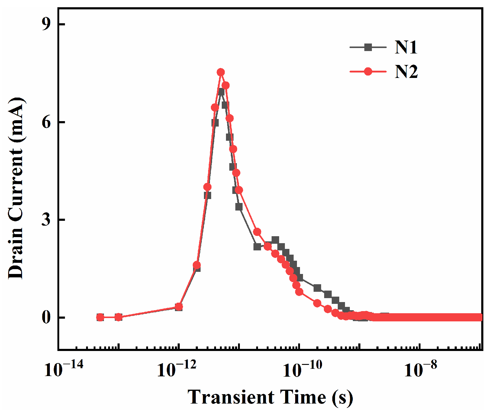
Simultaneously, with N1 having a smaller width-to-length ratio than N2, the DD causes more pronounced degradation to the electrical parameters of N1, as illustrated in Figure 12. For the storage state “0”, the transient drain current collected by the off-state NMOS (N2) under particle irradiation is larger. In summary, after experiencing displacement damage, the SRAM storage state “0” is more prone to flipping, indicating a larger SEU cross-section.

5. Summary

This study employed a proton accelerator to conduct 20–80 MeV high-energy proton displacement damage irradiation and SEU experiments, focusing on the proton SEU sensitivity of a 500 nm process SRAM under different proton energy parameters. The experimental results revealed an overall trend of an increasing SEU cross-section with a rise in proton energy. On the other hand, for devices not subjected to proton displacement damage irradiation, the SEU cross-section of SRAM “1” was slightly larger than that of SRAM “0”, indicating that SRAM is more prone to upsetting when in state “1”. Conversely, for devices subjected to displacement damage irradiation, the SEU cross-section of SRAM “0” was slightly larger than that of SRAM “1”, signifying that SRAM is more susceptible to upsetting when in state “0”. To analyze the correlation between proton cumulative irradiation and the SEU cross-section in the early stage, Geant4 simulation was used to assess the impact of proton-nucleus reactions on deposited energy in the sensitive region for protons of different energies. The simulation results demonstrated an increase in secondary particle yield with rising incident proton energy, leading to a greater quantity of high linear energy transfer (LET) secondary particles and a higher likelihood of inducing SEU in the memory.
Furthermore, employing TCAD combined with SPICE, simulation calculations were performed on the SRAM SEU cross-section. The results indicated that for devices pre-irradiated with protons, proton-induced displacement damage to lattice atoms through Coulomb interactions led to degradation in the electrical performance of MOS structures. This impacted the distribution of the sensitive region in SRAM devices, with displacement damage having a more significant effect on state “0”, resulting in a larger SEU cross-section for state “0” after proton irradiation.

Author Contributions

Y.L.: Methodology, Software, Investigation, Writing—review and editing. R.C.: Conceptualization, Methodology, Writing—review and editing, Supervision. J.T.: Software, Investigation. Y.C.: Software, Investigation. B.M.: Investigation, Formal analysis. L.Z.: Investigation, Formal analysis. S.C.: Software, Investigation. H.L.: Investigation, Formal analysis. X.Z.: Conceptualization, Methodology. Y.X.: Conceptualization, Supervision. All authors have read and agreed to the published version of the manuscript.

Funding

The authors acknowledge support from National Natural Science Foundation of China (No. 12004329), Open Project of State Key Laboratory of Intense Pulsed Radiation Simulation and Effect (No. SKLIPR2115), Postgraduate Research and Practice Innovation Program of Jiangsu Province (No. SJCX22_1704), and Innovative Science and Technology Platform Project of Cooperation between Yangzhou City and Yangzhou University, China (Nos. YZ202026301 and YZ202026306).

Data Availability Statement

Data are contained within the article.

Acknowledgments

The authors are grateful to Hantao Jin and Zhixin Tan in China Spallation Neutron Source for their support with proton irradiation.

Conflicts of Interest

The authors declare that they have no known competing financial interests or personal relationships that could have appeared to influence the work reported in this paper.

References

  1. Sun, X.; Saadat, O.I.; Chen, J.; Zhang, E.X.; Cui, S.; Palacios, T.; Fleetwood, D.M.; Ma, T.P. Total-Ionizing-Dose Radiation Effects in AlGaN/GaN HEMTs and MOS-HEMTs. IEEE Trans. Nucl. Sci. 2013, 60, 4074–4079. [Google Scholar] [CrossRef]
  2. Luo, Y.; Zhang, F.; Pan, X.; Guo, H.; Wang, Y. Impact of Total Ionizing Dose on Low Energy Proton Single Event Upsets in Nanometer SRAM. IEEE Trans. Nucl. Sci. 2019, 66, 1848–1853. [Google Scholar] [CrossRef]
  3. Luo, Y.-Y.; Zhang, F.-Q.; Pan, X.-Y.; Guo, H.-X.; Wang, Y.-M. Dependence of single event upsets sensitivity of low energy proton on test factors in 65 nm SRAM. Chin. Phys. B 2018, 27, 078501. [Google Scholar] [CrossRef]
  4. Schwank, J.; Shaneyfelt, M.; Baggio, J.; Dodd, P.; Felix, J.; Ferlet-Cavrois, V.; Paillet, P.; Lambert, D.; Sexton, F.; Hash, G.; et al. Effects of particle energy on proton-induced single-event latchup. IEEE Trans. Nucl. Sci. 2005, 52, 2622–2629. [Google Scholar] [CrossRef]
  5. Ye, B.; Liu, J.; Wang, T.-S.; Liu, T.-Q.; Luo, J.; Wang, B.; Yin, Y.-N.; Ji, Q.-G.; Hu, P.-P.; Sun, Y.-M.; et al. Impact of energy straggle on proton-induced single event upset test in a 65-nm SRAM cell. Chin. Phys. B 2017, 26, 088501. [Google Scholar] [CrossRef]
  6. Jiang, R.; Zhang, E.; McCurdy, M.W.; Wang, P.; Gong, H.; Yan, D.; Schrimpf, R.D.; Fleetwood, D.M. Dose-Rate Dependence of the Total-Ionizing-Dose Response of GaN-Based HEMTs. IEEE Trans. Nucl. Sci. 2019, 66, 170–176. [Google Scholar] [CrossRef]
  7. Brewer, R.M.; Zhang, E.X.; Gorchichko, M.; Wang, P.F.; Cox, J.; Moran, S.L.; Ball, D.R.; Sierawski, B.D.; Fleetwood, D.M.; Schrimpf, R.D.; et al. Total Ionizing Dose Responses of 22-nm FDSOI and 14-nm Bulk FinFET Charge-Trap Transistors. IEEE Trans. Nucl. Sci. 2021, 68, 677–686. [Google Scholar] [CrossRef]
  8. Zhao, S.E.; Bonaldo, S.; Wang, P.; Zhang, E.X.; Waldron, N.; Collaert, N.; Putcha, V.; Linten, D.; Gerardin, S.; Paccagnella, A.; et al. Total-Ionizing-Dose Effects on InGaAs FinFETs with Modified Gate-Stack. IEEE Trans. Nucl. Sci. 2020, 67, 253–259. [Google Scholar] [CrossRef]
  9. Li, K.; Zhang, E.X.; Gorchichko, M.; Wang, P.F.; Reaz, M.; Zhao, S.E.; Hiblot, G.; Van Huylenbroeck, S.; Jourdain, A.; Alles, M.L.; et al. Impacts of Through-Silicon Vias on Total-Ionizing-Dose Effects and Low-Frequency Noise in FinFETs. IEEE Trans. Nucl. Sci. 2021, 68, 740–747. [Google Scholar] [CrossRef]
  10. Xiong, Y.; Feeley, A.T.; Wang, P.F.; Li, X.; Zhang, E.X.; Massengill, L.W.; Bhuva, B.L. Supply Voltage Dependence of Ring Oscillator Frequencies for Total Ionizing Dose Exposures for 7-nm Bulk FinFET Technology. IEEE Trans. Nucl. Sci. 2021, 68, 1579–1584. [Google Scholar] [CrossRef]
  11. Cao, J.; Wang, P.F.; Li, X.; Guo, Z.; Zhang, E.X.; Reed, R.A.; Alles, M.L.; Schrimpf, R.D.; Fleetwood, D.M.; Arreghini, A.; et al. Total-Ionizing-Dose Effects on Polycrystalline-Si Channel Vertical-Charge-Trapping Nand Devices. IEEE Trans. Nucl. Sci. 2022, 69, 314–320. [Google Scholar] [CrossRef]
  12. Huang, Y.-T.; Cui, X.-H.; Yang, J.-Q.; Ying, T.; Yu, X.-Q.; Dong, L.; Li, W.-Q.; Li, X.-J. Radiation effects of 50-MeV protons on PNP bipolar junction transistors. Chin. Phys. B 2022, 31, 028502. [Google Scholar] [CrossRef]
  13. Liu, B.; Li, Y.; Wen, L.; Zhou, D.; Feng, J.; Ma, L.; Zhang, X.; Cai, Y.; Wang, Z.; Fu, J.; et al. A study of hot pixels induced by proton and neutron irradiations in charge coupled devices. Radiat. Eff. Defects Solids 2020, 175, 540–550. [Google Scholar] [CrossRef]
  14. Ding, L.; Gerardin, S.; Bagatin, M.; Bisello, D.; Mattiazzo, S.; Paccagnella, A. Investigation of total ionizing dose effect and displacement damage in 65nm CMOS transistors exposed to 3MeV protons. Nucl. Instrum. Methods Phys. Res. 2015, 796, 104–107. [Google Scholar] [CrossRef]
  15. Gong, H.; Liao, W.; Zhang, E.X.; Sternberg, A.L.; McCurdy, M.W.; Davidson, J.L.; Reed, R.A.; Fleetwood, D.M.; Schrimpf, R.D.; Shuvra, P.D.; et al. Proton-Induced Displacement Damage and Total-Ionizing-Dose Effects on Silicon-Based MEMS Resonators. IEEE Trans. Nucl. Sci. 2018, 65, 34–38. [Google Scholar] [CrossRef]
  16. Li, X.; Yang, J.; Liu, C.; Bai, G.; Luo, W.; Li, P. Synergistic effects of NPN transistors caused by combined proton irradiations with different energies ScienceDirect. Microelectron. Reliab. 2018, 82, 130–135. [Google Scholar] [CrossRef]
  17. Zhao, P.; Li, B.; Liu, H.; Yang, J.; Jiao, Y.; Chen, Q.; Sun, Y.; Liu, J. The Effects of Total Ionizing Dose on the SEU Cross-Section of SOI SRAMs. Electronics 2022, 11, 3188. [Google Scholar] [CrossRef]
  18. Bacchini, A.; Furano, G.; Rovatti, M.; Ottavi, M. Total Ionizing Dose Effects on DRAM Data Retention Time. IEEE Trans. Nucl. Sci. 2014, 61, 3690–3693. [Google Scholar] [CrossRef]
  19. Wang, P.F.; Zhang, E.X.; Chuang, K.H.; Liao, W.; Gong, H.; Arutt, C.N.; Ni, K.; Mccurdy, M.W.; Verbauwhede, I.; Bury, E.; et al. X-Ray and Proton Radiation Effects on 40 nm CMOS Physically Unclonable Function Devices. IEEE Trans. Nucl. Sci. 2018, 65, 1519–1524. [Google Scholar] [CrossRef]
  20. Wang, P.; Perini, C.J.; O’Hara, A.; Gong, H.; Wang, P.; Zhang, E.X.; Mccurdy, M.W.; Fleetwood, D.M.; Schrimpf, R.D.; Pantelides, S.T.; et al. Total Ionizing Dose Effects and Proton-Induced Displacement Damage on MoS2-Interlayer-MoS2 Tunneling Junctions. IEEE Trans. Nucl. Sci. 2019, 66, 420–427. [Google Scholar] [CrossRef]
  21. Aziz, I.; Dancila, D.; Dittmeier, S.; Siligaris, A.; Dehos, C.; De Lurgio, P.M.; Djurcic, Z.; Drake, G.; Jimenez, J.L.G.; Gustaffson, L.; et al. Effects of proton irradiation on 60 GHz CMOS transceiver chip for multi-Gbps communication in high-energy physics experiments. J. Eng.-JOE 2019, 2019, 5391–5396. [Google Scholar] [CrossRef]
  22. Yang, T.; Shao, Z.; Cai, M.; Jia, X.; Han, J. Simulation of the Interaction’s Effects on Single Event Effects between High-Energy Particles and Interconnect Overlayers within Semiconductor Devices. J. Deep Space Explor. 2019, 6, 173–178. [Google Scholar]
  23. Han, J.; Guo, G. Characteristics of energy deposition from 1–1000 MeV proton and neutron induced nuclear reactions in silicon. Aip Adv. 2017, 7, 115220. [Google Scholar] [CrossRef]
  24. He, C.; Chen, X.; Li, G. Simulation Calculation for High Energy Proton Single Event Upset Effects. Chin. J. Comput. Phys. 2002, 19, 367–371. [Google Scholar]
  25. Grichine, V.M. Geant4 Electron–Proton Integral Inelastic Cross Section Models. IEEE Trans. Nucl. Sci. 2023, 70, 1186–1188. [Google Scholar] [CrossRef]
  26. Yu, Y.; Feng, G.; Chen, R.; Shangguan, S.P.; Han, J.W. Research of SEL sensitive region of CMOS SRAM by pulsed laser mapping facility. Spacecr. Environ. Eng. 2014, 31, 150–153. [Google Scholar]
  27. Li, P.; Zhang, M.; Zhang, W.; Zhao, Z.; Song, C.; Fan, H. Effect of charge sharing on SEU sensitive area of 40-nm 6T SRAM cells. IEICE Electron. Express 2014, 11, 20140051. [Google Scholar] [CrossRef]
  28. He, C.; Li, G.; Luo, J.; Liu, E. Analysis of single event upset in CMOS SRAMs. J. Semicond. 2000, 21, 174–178. [Google Scholar]
  29. Sungman, R.; Daewon, K.; Kyeongyeon, K.; Choi, S.; Park, B.G.; Park, Y.J. Extension of the Density-Gradient Model to the Second-Order Quantum Correction for Analysis of the Single-Charge Effect in Sub-10-nm MOS Devices. IEEE J. Electron Devices Soc. 2020, 8, 213–222. [Google Scholar]
  30. Holt, J.S.; Alamgir, Z.; Beckmann, K.; Suguitan, N.; Russell, S.; Iler, E.; Bakhru, H.; Bielejec, E.S.; Jacobs-Gedrim, R.B.; Hughart, D.R.; et al. Comparison of Radiation Effects in Custom and Commercially Fabricated Resistive Memory Devices. IEEE Trans. Nucl. Sci. 2019, 66, 2398–2407. [Google Scholar] [CrossRef]
  31. Colladant, T.; Flament, O.; L’Hoir, A.; Ferlet-Cavrois, V.; D’hose, C.; de Potcharra, J.D.P. Study of Transient Current Induced by Heavy-Ion in NMOS/SOI Transistors. IEEE Trans. Nucl. Sci. 2002, 49, 2957–2964. [Google Scholar] [CrossRef]
  32. Liu, Y.; Cao, R.; Li, H.; Zhao, L.; Han, D.; Liu, Y.; Zheng, S.; Zeng, X.; Xue, Y. Simulation study on the synergistic effect of TID and SEE on SEU sensitivity of SRAM. Spacecr. Environ. Eng. 2023, 40, 170–178. [Google Scholar]
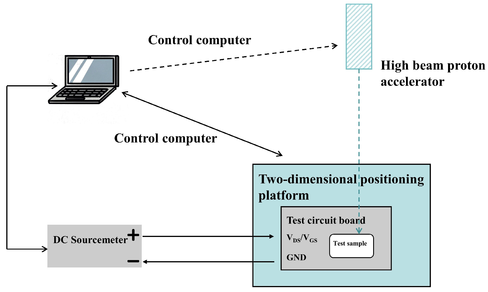
Figure 1. Schematic diagram of the SEU experiment.
Electronics 12 05028 g001
Figure 2. Structure of the 6T SRAM storage cell.
Electronics 12 05028 g002
Figure 3. Proton-induced SEU cross-sections: (a) SRAM #1, (b) SRAM #2.
Electronics 12 05028 g003
Figure 4. Schematic of SRAM structure including sensitive volume.
Electronics 12 05028 g004
Figure 5. Statistical diagram of secondary particles: (a) 20 MeV, (b) 40 MeV, (c) 60 MeV, (d) 80 MeV.
Electronics 12 05028 g005
Figure 6. Distribution of secondary heavy ion LET under proton irradiation with different energy levels.
Electronics 12 05028 g006
Figure 7. Characteristic curves of the devices. Transfer characteristic curve for NMOS (a) and PMOS (b), subthreshold current for NMOS (c) and PMOS (d), gate current for NMOS (e) and PMOS (f).
Electronics 12 05028 g007
Figure 8. Comparison of transient drain current values with and without displacement damage: (a) NMOS, (b) PMOS.
Electronics 12 05028 g008
Figure 9. Cross-sections for SRAM: (a) SRAM #1, (b) SRAM #2.
Electronics 12 05028 g009
Figure 10. Distribution of the carrier recombination rate: (a) pristine NMOS, (b) NMOS with DD, (c) pristine PMOS, and (d) PMOS with DD.
Electronics 12 05028 g010
Figure 11. Subthreshold current curve for devices with different width–length ratios: (a) NMOS and (b) PMOS.
Electronics 12 05028 g011
Figure 12. Transient drain current values in devices with different width–length ratios.
Electronics 12 05028 g012
Table 1. Beam conditions for the proton-induced SEU experiments on SRAM.
DeviceSRAM #1SRAM #2
Step
Step #1Energy (MeV)/Fluence (p/cm2) 80/1 × 1014
Step #2Energy (MeV)/Fluence (p/cm2)20/9.45 × 10920/9.45 × 109
40/8.35 × 10940/8.35 × 109
60/1.29 × 101060/1.29 × 1010
Table 2. Statistical results of SRAM upsetting counts.
ItemUpsetting Counts
20 MeV40 MeV60 MeV
SRAM #11-0194675
0-1245789
SRAM #21-01057112
0-193789
Table 3. Structure and process parameters of MOS devices.
ParameterValue
Gate length/nm500
Channel doping concentration/cm−32 × 1018
Source/drain doping concentration/cm−32 × 1020
Source/drain junction depth/nm180
Gate oxide thickness/nm10
Body region doping concentration/cm−31 × 1017
Disclaimer/Publisher’s Note: The statements, opinions and data contained in all publications are solely those of the individual author(s) and contributor(s) and not of MDPI and/or the editor(s). MDPI and/or the editor(s) disclaim responsibility for any injury to people or property resulting from any ideas, methods, instructions or products referred to in the content.