Article

A Fault-Tolerant Bidirectional Converter for Battery Energy Storage Systems in DC Microgrids

by
Mohammad Saeed Mahdavi
1,
Mohammad Saleh Karimzadeh
1,
Tohid Rahimi
2 and
Gevork Babamalek Gharehpetian
1,*
1
Department of Electrical Engineering, Amirkabir University of Technology, Tehran 15875, Iran
2
Department of Electronics, Carleton University, Ottawa, ON K1S 5B6, Canada
*
Author to whom correspondence should be addressed.
Electronics 2023, 12(3), 679; https://doi.org/10.3390/electronics12030679
Submission received: 20 December 2022 / Revised: 26 January 2023 / Accepted: 27 January 2023 / Published: 29 January 2023

Abstract

:
Battery energy storage systems (BESSs) can control the power balance in DC microgrids through power injection or absorption. A BESS uses a bidirectional DC–DC converter to control the power flow to/from the grid. On the other hand, any fault occurrence in the power switches of the bidirectional converter may disturb the power balance and stability of the DC microgrid and, thus, the safe operation of the battery bank. This paper presents a fault-tolerant topology along with a fault diagnosis algorithm for a bidirectional DC–DC converter in a BESS. The proposed scheme can detect open circuit faults (OCFs) and reconfigure the topology to guarantee the safe and continuous operation of the system while it is connected to the DC microgrid. The proposed method can be extended to multi-phase structures of interleaved bidirectional DC–DC converters using only two power switches and n TRIACs to support the OCF occurrence on 2 × n switches of n legs. The proposed fault diagnosis algorithm detects OCFs only by observing the current of the inductors and does not require any sensor. Hence, the cost, weight, volume and complexity of the system is considerably reduced. Experimental results show that the reconfiguration of the converter, along with its fast fault detection, leads to fewer switches overloading and less DC voltage deviation.

1. Introduction

Nowadays, with the ever-increasing use of distributed generation (DG) technologies such as wind turbines and photovoltaic systems, energy storage systems play an important role in power systems and microgrids. DC resources, loads and storages lead to more cost and complexity of AC microgrids because they need more DC–AC and AC–DC converters. To address these issues, DC microgrids were introduced as a suitable alternative for AC microgrids [1,2]. In DC microgrids, BESSs are commonly used to control the power balance between the load and generation. It is an essential condition for stable operation of the system.
In recent years, an increasing number of studies have focused on BESS applications such as electric vehicles [3], aircrafts [4], microgrids [5] or power systems [6]. BESSs needs a power electronic converter to control its power flow. A bidirectional converter was proposed in [7] to control the BESS power along with a diesel generator in an aircraft. BESSs are able to inject and absorb power to/from the grid through a bidirectional DC–DC converter [8]. Figure 1a shows the most well-known bidirectional DC–DC converter topology, which is commonly used to connect the battery bank to the DC grid [9]. This converter is limited at high power levels due to the use of an inductor in its structure.
Moreover, some of the literature focused on isolated topologies for BESSs such as dual active bridge (DAB) [10,11], NPC-based DAB [12], LLC resonant converter [13] and high-gain, non-isolated, bidirectional DC–DC converters [14,15]. Nevertheless, high-frequency transformers and coupled inductors increase their manufacturing cost, losses and complexity. To overcome the limitation of the conventional converter in Figure 1a for high power applications, interleaved multi-phase bidirectional converters, as depicted in Figure 1b, were introduced [16,17]. As can be seen in this figure, to reduce the size of inductor, the total input current is divided into parallel legs.
Due to the important role of BESSs in the power balance of DC grids, it is necessary to guarantee their reliable operation against fault occurrences in the bidirectional converter or battery bank. In [18], a unified control system was presented to estimate the state of charge and detect the fault occurrence in battery bank simultaneously by using a fuzzy observer. Once a fault occurs in the battery bank, its output voltage decreases. Another probable scenario is fault occurrence in the power switches of a bidirectional converter. In [19,20,21], different types of faults that may occur in power switches were investigated and categorized into two groups: (i) open circuit faults (OCFs) and (ii) short circuit faults (SCFs). SCFs cause severe damage in an instant and must be quickly removed [22,23]. On the other hand, OCFs do not cause the absolute failure of the converter. Thus, power transfer can be continued, but in the long term, it may cause the failure of the converter and its components. Hence, it is important to detect and fix it [24]. In [25], a method was proposed to detect OCFs in the DC–DC converter of a photovoltaic system and fix them by changing the converter’s topology. Additional inductors and power switches increase the weight, volume and cost of the converter. In addition, it requires additional voltage and current sensors for fault detection.
An observer-based fault diagnosis method for induction machine drives was proposed in [26]. The computational burden and the complexity of this method is relatively high. Many fault diagnosis methods [27,28,29,30] use the current measurement to reduce the computational burden. On the other hand, some other studies used the voltage measurement to increase fault detection speed. In [31], a fault-tolerant topology was introduced for quasi-Z-source inverters along with a fault detection method based on the capacitor’s voltage measurement.
Fault-tolerant topologies usually change the configuration of the circuit after the fault. Until now, many fault-tolerant topologies have been introduced for different types of converters, such as full-bridge [32], Z-source [31], triple active bridge [33] or Half-Bridge LLC Resonant converters [34]. In [35], a fault detection and correction method was presented for interleaved three-phase boost converters. This method was based on sampling the voltage of the inductors. Although the number of additional components for fault correction is less than [25], it suffers from more complexity in its control system. In [36], a fault diagnosis method was introduced based on the Luenberger observer for a DC–DC converter of a fuel cell. Despite the simplicity of the implementation, it can only detect the fault, and it does not provide a solution for reconfiguring the converter topology to remove the fault. Another strategy to detect the OCF is to compare the inductor current as estimated by using an observer with its sensor-measured value. To reduce the number of sensors used, a state observer is created using the information available in the closed loop control [37,38]. In [39,40] a fault diagnosis method was proposed for a three-leg interleaved boost converter based on inductor current sampling.
In this paper, a fault-tolerant topology and a fault diagnosis method are proposed for n-leg interleaved bidirectional converters against OCF occurrences in power switches. The proposed topology does not require any additional inductors. Its additional components include only two power switches and n TRIACs to support OCF occurrences in 2 × n switches of n legs. The proposed fault diagnosis algorithm detects an OCF only by observing the current of the inductors and does not require any sensors. Hence, the cost, weight, volume and complexity of the system is considerably reduced. Fast reconfiguration of the converter along with fast fault detection causes the switches to face the least overloading. In addition, the converter senses the lowest interrupt in its normal operation without any efficiency drop.

2. Proposed Fault-Tolerant Bidirectional Topology

2.1. Basic Configuration

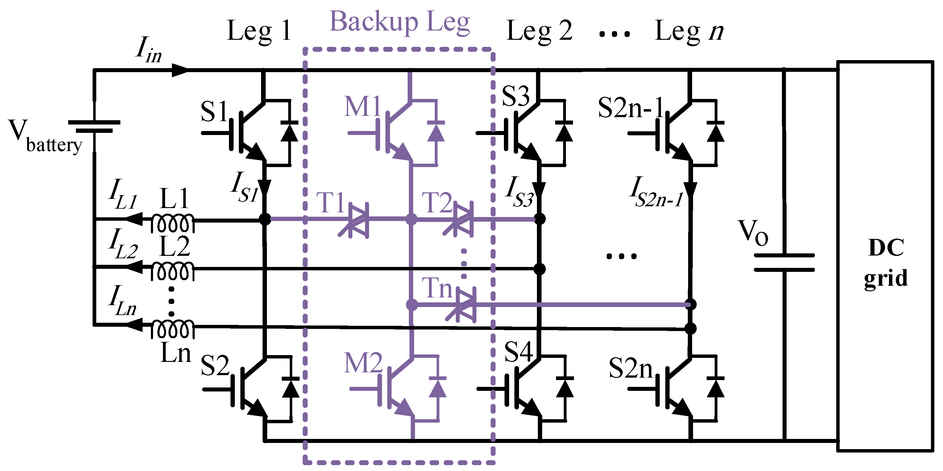
The proposed BESS topology is depicted in Figure 2. In this scheme, a battery bank is connected to a DC microgrid through the proposed OCF-tolerant bidirectional DC–DC converter.
In the proposed topology, a backup leg is added to an n-leg interleaved bidirectional DC–DC converter. The backup leg, including two power switches, M1 and M2, is shown inside the dashed lines in Figure 2. It is connected to all of the other legs with TRIACs, which are triggered only when an OCF is detected on that leg. Thus, the backup leg is connected to the other n legs through n TRIACs: T1, T2, … and Tn. As can be seen in this figure, only two additional switches and n TRIACs are required to eliminate any possible OCF at 2 × n switches in n legs of the bidirectional converter. The extra devices are inside the dashed line in Figure 2. Therefore, in the proposed OCF-tolerant topology, very few extra components are needed compared with the conventional topology.

2.2. Normal State Operation

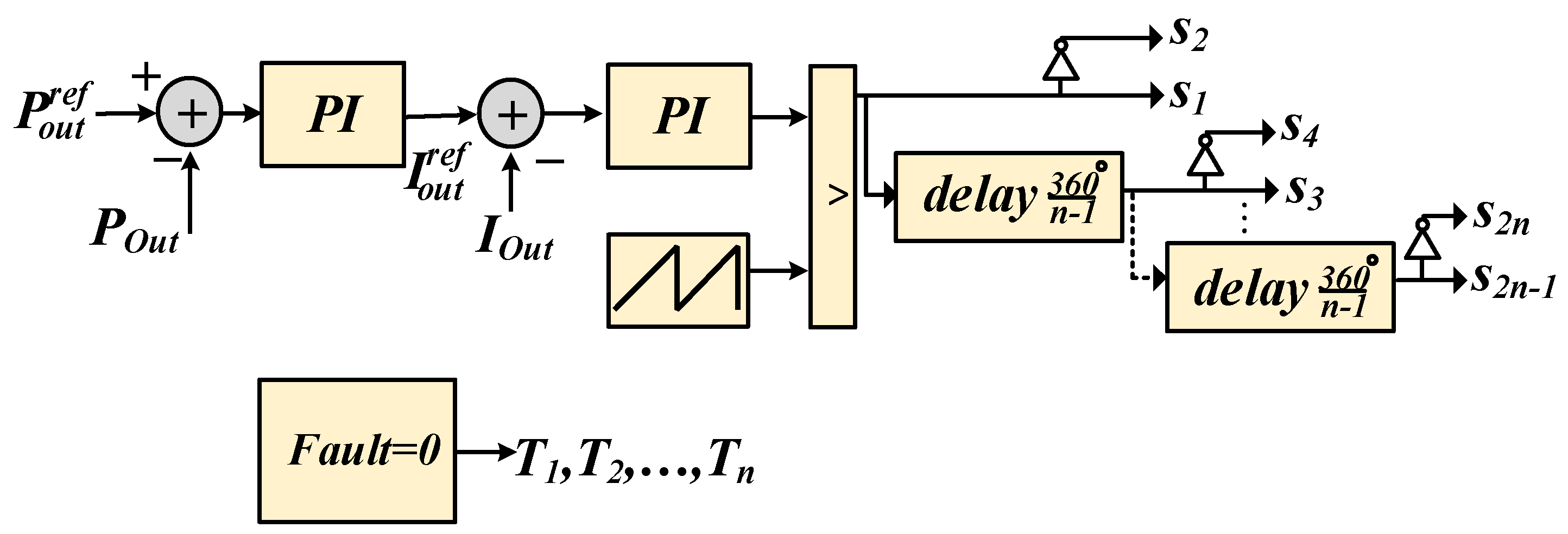
Under normal conditions, the converter operates with conventional topology, where the switches S 1 ,   S 3 , S 5   to   S 2 n 1 are controlled in forwarding mode for power injection to the DC microgrid, and switches S 2 ,   S 4 , S 6   to   S 2 n   are controlled in reverse mode for power absorption from the DC microgrid. Different control systems can be used to control an n-leg interleaved bidirectional DC–DC converter under normal conditions. One of these control systems is depicted in Figure 3. According to this scheme, a two-stage cascaded control system is employed to control the power flow. In the first stage, a PI-based power controller regulates the power injection/absorption to/from the grid ( P o u t ) and generates the reference current ( I o u t r e f ) for the next stage. In the second stage, a PI-based current controller is utilized to track the reference current and generate the modulation signal for the PWM unit. It should be noted that the switching pulses for each leg are commonly shifted by 360 / ( n 1 ) relative to the pulses of the previous leg.
It is possible to analyze the circuit in three states: (i) the normal state (operation without faults), (ii) the faulty state (transient after an open-circuit power switch fault), and (iii) the rebuilt state (post-fault operation with the proposed fault-tolerant strategy requiring hardware and software reconfiguration). In this paper, without loss of generality, a two-leg interleaved bidirectional topology is studied, but the proposed method can be simply extended to an n-leg topology. In the normal state, if the converter has two interleaved inductors and four power switches, then it is characterized by four operating modes according to the power direction. In each operating mode, two switches are conducting, and the others have to be turned off. The normal operation of the conventional topology can be found in [41].

2.3. Control System Design

A control system in the normal state consists of two cascaded PI controllers. In order to design the parameters of these controllers, the system is modeled in s-domain considering a second-order transfer function for DC–DC converters [42] and a Thevenin equivalent circuit for DC microgrid with inductance L g and resistance R g , as depicted in Figure 4. Firstly, the coefficients of the inner loop must be tuned. Then, the coefficients of the outer loop are designed. The inner loop is a PI current controller with proportional gain k p 2 and integral gain k i 2 . Considering the dominant poles of the closed loop transfer function, it corresponds to the typical second-order transfer function with the bandwidth ω n and damping factor ξ. It is possible to select k p 2 and k i 2 so that ω n and ξ are set to desired values. The same method is used to tune k p 1 and k i 1 in the outer loop with lower bandwidth.

2.4. Faulty State Operation

In the case of an open circuit fault in any of the switches, if it occurs in the upper switches ( S 1 ,   S 3 , S 5   to   S 2 n 1 ), then the bidirectional converter fails in forward mode, which causes current to flow through the switches in parallel with the faulty switch and will cause the parallel switch to be damaged by overcurrent. On the other hand, if the OCF occurs in the lower switches ( S 4 ,   S 6 , S 8   to   S 2 n ), then the bidirectional converter fails in reverse mode. This will cause the parallel low-side switch to be damaged by overcurrent.
Figure 5 illustrates the operating modes of a bidirectional converter with two interleaved inductors and four power switches when each power switch experiences an open circuit fault before detecting and diagnosing the fault. In the forward mode of the bidirectional converter, when an open circuit fault occurs in   S 1 , two operating modes are possible for the converter (as shown in Figure 5a): in the first interval, S 3 is on and the rest of the switches are off, and in the second interval, all switches are off. During the period where S 3 is on, diode D 4 is reverse-biased, and inductor L 2 is charged from the input source. In addition,   D 2 is forward-biased, which causes the inductor to discharge until it reaches zero current.
Assuming that all elements are ideal, the supply voltage and input power are constant and the inductance values of   L 1 and   L 2 are equal, during one switching period, the equations of the input and inductor currents are as follows:
  I i n , a v e = I L 1 , a v e + I L 2 , a v e
I L 1 , a v e = I L 2 , a v e = I  
Combining Equations (1) and (2), the equation of the input current can be obtained as below:
  I i n , a v e = 2 I
After the inductor current L 1 becomes zero, Equation (2) is rewritten as below:
  I L 2 , a v e = I s 3 , a v e = 2 I
I L 1 , a v e = I s 1 , a v e = 0
In the above equation, it is evident that when an OCF occurs in the power switch   S 1 , a current twice the nominal current passes through L 2   and   S 3 , causing damage. Similarly, the current through inductor L 1   and switch S 1 reach twice the rated current when an OCF occurs in switch   S 3 , as shown in Figure 5b.
During reverse mode, if there is an OCF in the   S 2 , two operating modes are possible for the converter (Figure 5c): in the first interval,   S 4 is on and the rest of the switches are off, whereas in the second interval, all switches are off. During the period where S 4 is on, D 3 is reverse-biased, the DC grid charges the inductor   L 2 , and   D 1 is also forward-biased. As a result, the inductor charges the battery until it reaches zero current. Similar to forward mode, this mode damages the switch   S 4 by passing twice the rated current through it. On the other hand, if an OCF occurs in   S 4 , S 2   must carry twice its rated current, as shown in Figure 5d.
The topology and control system are reconfigured after the fault is detected by using the proposed fault diagnosis algorithm. Depending on where the fault is located, circuit reconfiguration varies slightly. Figure 6 shows the reconfigured topologies for fault occurrences on each switch.

2.5. Fault Diagnosis Algorithm

Under normal conditions, during the forward mode of the bidirectional converter and when the switches   S 1 ,   S 3 , … to S 2 n 1 are turned on with a specific duty cycle, the inductor’s current increases in all legs. Similarly, in reverse mode and where the switches   S 2 ,   S 4 , … to S 2 n are turned on with a specific duty cycle, the absolute value of the inductor’s current increases. An OCF occurrence on each switch of each leg of the converter causes the current of the inductor of the same leg to decrease while the currents of the other inductors increase. Therefore, by observing the currents of inductors and their changes over time, it is possible to detect the OCF.
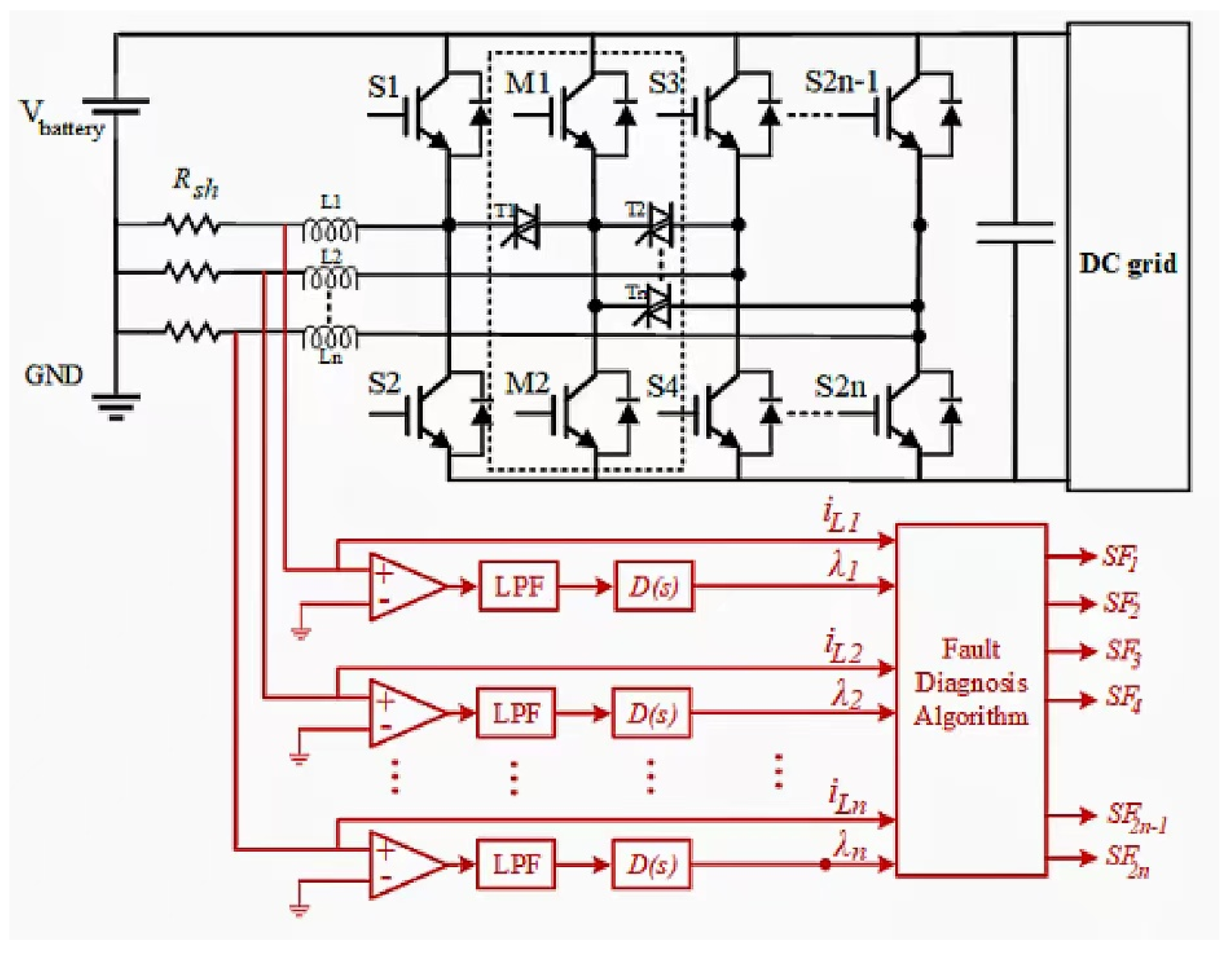
The proposed fault diagnosis scheme for an n-leg bidirectional converter is presented in Figure 7. In this scheme, inductors’ currents i L 1 ,   i L 2 ,   ,   i L n are measured using small series resistors. In fact, a major advantage of the proposed topology is that it allows the inductors’ currents to be measured without any current sensors and only with small series resistors because all inductors are ground-connected. Then, for the k-th leg, the measured current i L k passes through a low-pass filter (LPF) with the following transfer function in the z-plane:
LPF ( z ) = β z z β
where β = 1 / ( ω c T s + 1 ) , ω c is the filter’s cutoff frequency and T s is the sample rate of discretization. This filter removes the high-frequency terms and noise of the signal. Then, the filtered signal passes through a discrete transfer function D(z) as follows:
D ( z ) = N 1 + N T s z z 1  
It is a causal form of the derivative function discretized using the backward Euler method to determine the changes of the signal over time. N is the filter coefficient. Outputs of this stage λ 1 ,   λ 2 ,     to   λ n are used in the fault diagnosis algorithm along with the measured values of inductors’ currents i L 1 ,   i L 2 ,     to   i L n . The proposed fault diagnosis algorithm is presented in the flowchart of Figure 8.
The first question is whether an OCF occurred or not. The second question is which leg the fault occurred in. Finally, the third question is which switch of that leg is the open circuit. To detect the OCF occurrence in Figure 7, it is enough to analyze the product of λ 1 ,   λ 2 ,   and   λ n . According to Figure 8, if the resulting value of λ 1 × λ 2 ,   × λ n is less than a negative threshold value λ t h , then an OCF has occurred. At this time, each leg with a negative corresponding λ value is faulty. Thus, as depicted in Figure 8, if λ k < 0 , then an OCF has occurred on the switches of the k-th leg. To find out which one of upper and lower switches in k-th leg is faulty, it is enough to check the sign of inductor’s current in that leg. If i L k is positive, then the upper switch is faulty; otherwise, the lower switch is faulty. According to the algorithm in Figure 8, if the switch S k is faulty, then the parameter S F k is set to 1; otherwise, it is set to zero.

2.6. Reconfiguration Method for Fault-Tolerant Operation

Once the faulty switch is detected by using the proposed fault diagnosis scheme, the circuit is reconfigured to replace the faulty switch with one of the backup switches M1 and M2. A detailed scheme of the hardware and software reconfiguration is shown in Figure 9. When the converter operates under normal conditions, switches M1 and M2 do not receive any pulses from the control system, and none of the TRIACs T1, T2, … to Tn are activated. Once an OCF occurs on one of the power switches of the k-th leg, the TRIAC Tk is activated. If the upper switch is faulty, then M1 is triggered by the pulses of the open circuit switch. If the lower switch is faulty, then M2 is triggered by the pulses of the open circuit switch.
As depicted in Figure 9, to generate the switching pulses for backup switches M1 and M2, the reconfiguration system employs the switching pulses S 1 ,   S 2 , … to S 2 n generated from the control system along with the parameters S F 1 ,   S F 2 , … to S F 2 n generated from the fault diagnosis algorithm. In this logic design, if S F 2 k 1 is set to 1, then an OCF has occurred on an upper-side switch; thus, the switching pulses S 2 k 1 will be applied to switch M1. On the other hand, if the OCF occurs on a lower-side switch, then S F 2 k is set to 1, and the switching pulses S 2 k will be applied to switch M2.

3. Results

3.1. Simulation Results

This section presents the simulation results of the proposed fault-tolerant topology and fault diagnosis algorithm for a sample two-leg interleaved bidirectional converter connected to a DC microgrid. The simulated converter had two interleaved inductors and four power switches along with two additional backup switches. The characteristics and parameters of the converter are listed in Table 1. The simulation results were caried out using the MATLAB/Simulink software. The SimScape toolbox was used to demonstrate the performance accuracy of open-circuit fault detection and fault-tolerant reconfiguration. In addition, ω c = 50   kHZ , λ t h = 100 , T s = 10   us and N = 100 .
At first, the converter operation in forward mode was analyzed without fault diagnosis and fault-tolerant reconfiguration. Figure 10 illustrates the current flowing through the switch S1 in the forward operation mode of the converter before and after an OCF occurred in the switch S3 at t = 1 s. As can be seen in the figure, before the fault occurrence, the output current was equally divided between two switches. However, after the fault occurrence, the currents of the switches in the faulty leg became zero, and the currents of the switches in the other leg were doubled. This overload will lead to damage in the switches of the other leg. If an OCF occurs on the switch S3, then similar results will be obtained.
To analyze the converter operation in reverse mode, Figure 11 shows the current of the switch S2 before and after an OCF occurred on the switch S4 at t = 1 s. The currents of the switches in the faulty leg became zero, and the currents of the switches in the other leg were doubled. If an OCF occurs on the switch S2, then similar results will be obtained.
In the proposed fault diagnosis and fault-tolerant system, once the converter detects the fault occurrence, it is reconfigured using TRIACs T1 or T2. Therefore, the backup switch M1 or M2 is turned on, and the additional current of the healthy switch passes through it to prevent damage to the healthy switch.
Using the proposed fault diagnosis method and fault-tolerant reconfiguration, the simulation results for when an OCF occurs on the switch S3 in forward mode are presented in Figure 12. It shows the current flowed through the switches S1 and M1 in forward mode, and when a fault on the switch S3 was detected, the topology was reconfigured by turning on the switch T2. In reverse mode, considering an OCF on the switch S4 at t = 1 s, Figure 13 shows the currents of switches S2 and M2 after the fault diagnosis and topology reconfiguration by turning on the switch T2.
As can be inferred from these figures, due to fast fault detection and reconfiguration, the proposed fault-tolerant system was able to quickly remove the overload of the switches S1 and S2 within about 0.6 s. The maximum overload was limited to 8 A. The output voltage and output current of the converter in forward and reverse modes are shown in Figure 14a,b, respectively.

3.2. Experimental Results

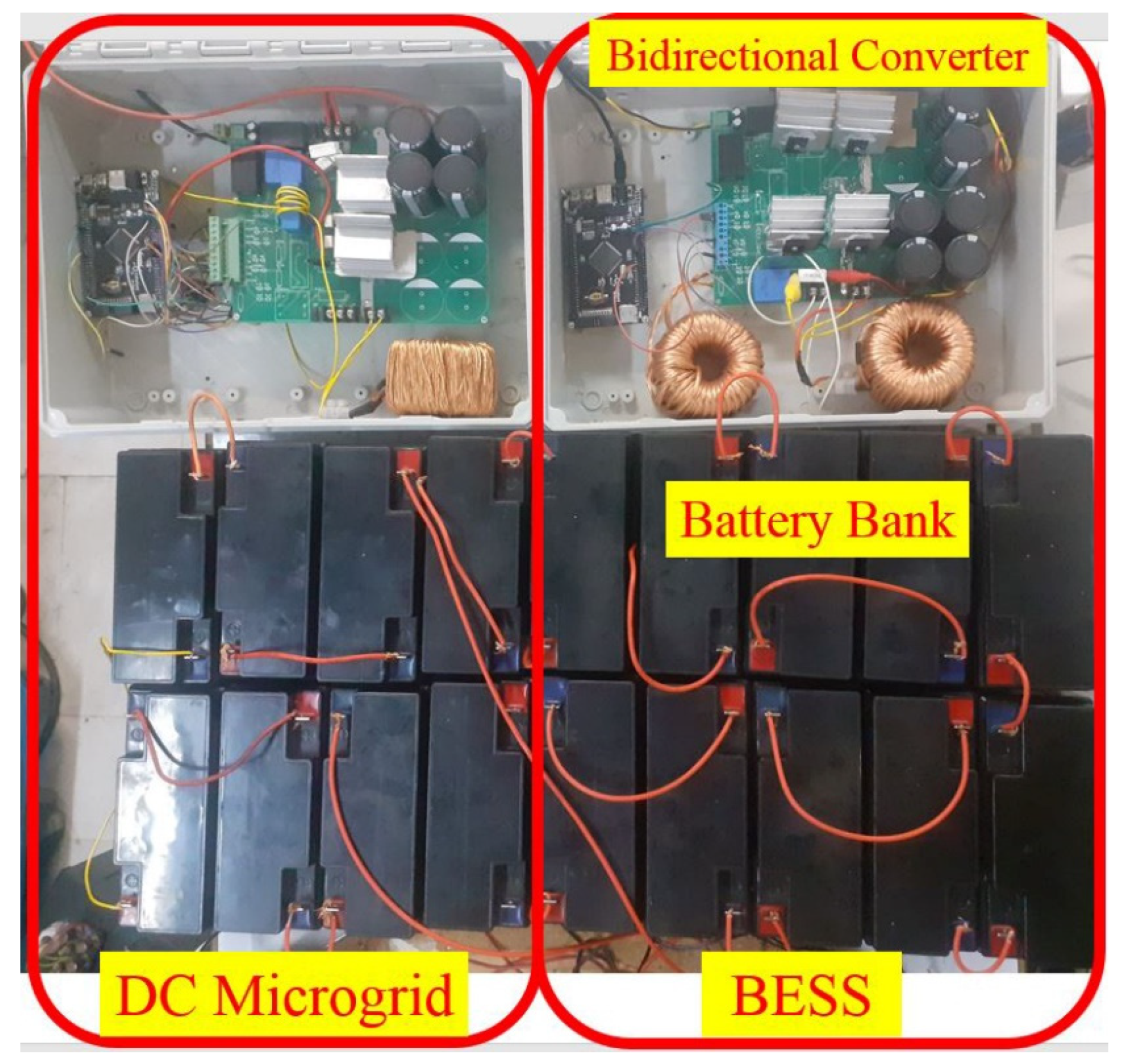
To experimentally verify the performance of the proposed fault-tolerant topology and fault diagnosis algorithm, an experimental prototype for the proposed BESS was implemented and connected to a laboratory-scale DC microgrid. As shown in Figure 15, the BESS consisted of a lead-acid battery bank along with the proposed fault-tolerant two-leg interleaved bidirectional converter with an additional backup leg. The BESS was connected to a DC microgrid including another BESS and a DC load. The second BESS regulated the DC bus voltage of the microgrid. The proposed BESS was connected to the DC bus and injected/absorbed the reference current to/from it. The proposed fault diagnosis algorithm was implemented on the STM32F407ZGT6 digital microcontroller with a 168 MHz CPU clock. The fault diagnosis algorithm and switching control system were implemented with 200 kHz and 10 kHz frequencies, respectively, in separated interrupt routines. BT139 was used for TRIACs T1 and T2. In addition, ω c = 50   kHz , λ t h = 100 , T s = 10   us and N = 100 .
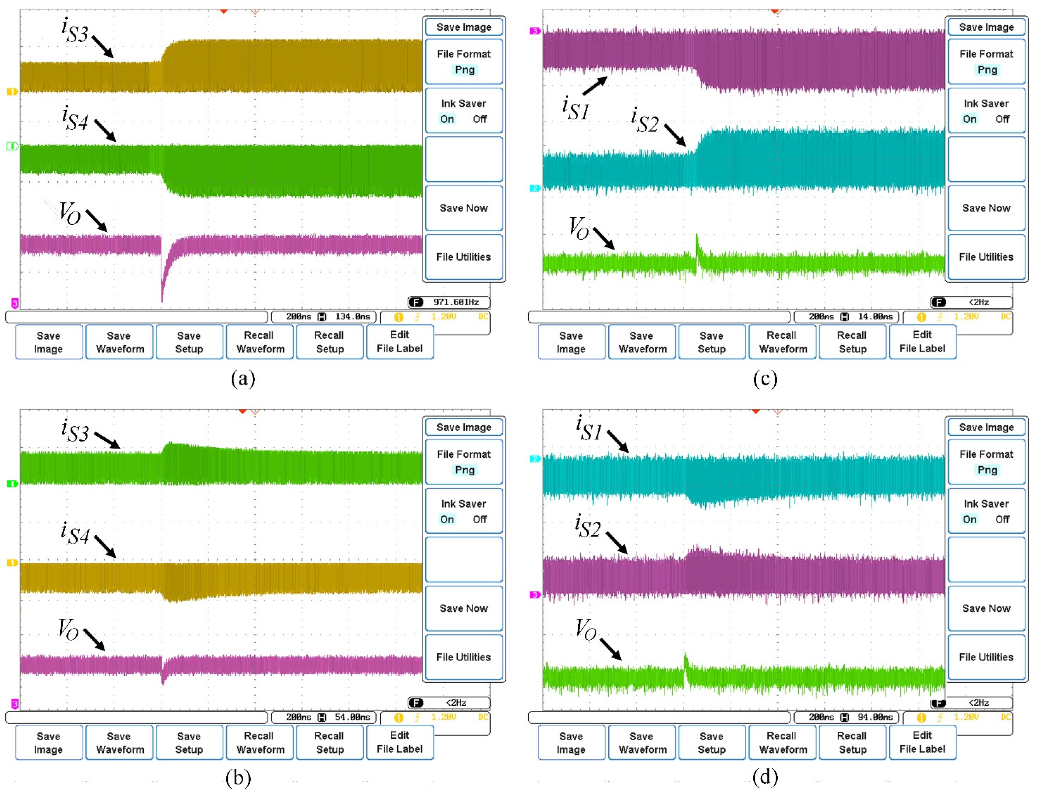
Figure 16 shows the experimental results, including the currents of the switches in the healthy leg and the output voltage of the converter while an OCF occurred on power switches S1 and S4 in forward and reverse modes, respectively. At first, a two-leg interleaved bidirectional converter without the fault-tolerant strategy was tested. In forward mode, once an OCF occurred on the switch S1, the current flowing through switches S3 and S4 and the output voltage of the converter were as illustrated in Figure 16a. Because there was no fault-tolerant strategy, the currents of S3 and S4 were doubled. In addition, a considerable drop occurred in the output voltage.
To overcome these issues, the proposed fault-tolerant system and fault diagnosis method were experimentally implemented. Figure 16b illustrates the performance of the proposed system in removing the overload of switches S3 and S4 and limiting the output voltage drop when an OCF occurred on the switch S1 in forward mode.
In reverse mode, first, a two-leg converter was tested without the fault-tolerant strategy for an OCF on the switch S4. The current that flowed through switches S1 and S2 and the output voltage of the converter can be seen in Figure 16c. Because there was no fault-tolerant strategy, the currents of S1 and S2 in the healthy leg were doubled. In addition, a considerable drop occurred in the output voltage. Using the proposed fault-tolerant strategy, Figure 16d shows that the system was able to remove the overload of switches S1 and S2 and limit the output voltage drop in reverse mode.
According to Figure 16, the maximum overload was limited to 8.5 A, and the maximum settling time was about 400 ms to completely remove the overload. Analyzing the generated pulses for the TRIACs, it is possible to measure the computation time of the fault diagnosis algorithm. The proposed method can practically detect the OCF occurrence and the fault location within 18 ms.
In Table 2, the performance of the proposed fault diagnosis algorithm is compared with other references in terms of fault detection speed, computational burden and complexity. The proposed method can be simply implemented on the microcontroller. In addition, its fault detection speed was more than other methods except for that of reference [30], whose complexity is greater than that of the proposed method.

4. Conclusions

A fault diagnostic method and a fault-tolerant reconfiguration are presented in this study for a bidirectional DC–DC converter in a BESS. This method uses only the inductor current, its changes, and the series resistance for fault diagnosis without any sensors. Hence, its implementation is simple and cost-effective. It is able to indicate an OCF occurrence and its location. For an n-leg interleaved bidirectional converter, two power switches are added and one TRIAC is required for each leg. As soon as a fault is detected by the proposed fault diagnosis algorithm, a fault-tolerant reconfiguration is initiated. Switches and TRIACs are switched in such a way that the overcurrent in a healthy switch does not damage it. An OCF in one switch causes the currents of switches in the other legs increase, causing damage and disrupting the converter’s performance. Experimental results show that the fast fault detection within 18 ms and automatic reconfiguration caused the overload in the other switches to be quickly removed, and thus, the voltage deviation was limited.

Author Contributions

Conceptualization, M.S.M.; methodology, M.S.M.; software, M.S.M. and M.S.K.; validation, M.S.M., M.S.K., G.B.G. and T.R.; formal analysis, M.S.M. and M.S.K.; investigation, M.S.M. and M.S.K.; resources, M.S.K.; data curation, M.S.K.; writing—original draft preparation, M.S.K.; writing—review and editing, M.S.M.; visualization, M.S.K.; supervision, G.B.G.; project administration, G.B.G. and M.S.M.; funding acquisition, T.R. All authors have read and agreed to the published version of the manuscript.

Funding

This research was funded the by Iran National Science Foundation (INSF) (Project No. 99030519).

Data Availability Statement

The data provided in this study can be obtained from the corresponding authors.

Conflicts of Interest

The authors declare no conflict of interest.

References

  1. Chandra, A.; Singh, G.K.; Pant, V. Protection techniques for DC microgrid-A review. Electr. Power Syst. Res. 2020, 187, 106439. [Google Scholar] [CrossRef]
  2. Sarangi, S.; Sahu, B.K.; Rout, P.K. A comprehensive review of distribution generation integrated DC microgrid protection: Issues, strategies, and future direction. Int. J. Energy Res. 2021, 45, 5006–5031. [Google Scholar] [CrossRef]
  3. Caines, A.; Ghosh, A.; Bhattacharjee, A.; Feldman, A. The Grid Independence of an Electric Vehicle Charging Station with Solar and Storage. Electronics 2021, 10, 2940. [Google Scholar] [CrossRef]
  4. Sumsurooah, S.; He, Y.; Torchio, M.; Kouramas, K.; Guida, B.; Cuomo, F.; Atkin, J.; Bozhko, S.; Renzetti, A.; Russo, A.; et al. ENIGMA—A Centralised Supervisory Controller for Enhanced Onboard Electrical Energy Management with Model in the Loop Demonstration. Energies 2021, 14, 5518. [Google Scholar] [CrossRef]
  5. Yan, X.; Wang, C.; Wang, Z.; Ma, H.; Liang, B.; Wei, X. A United Control Strategy of Photovoltaic-Battery Energy Storage System Based on Voltage-Frequency Controlled VSG. Electronics 2021, 10, 2047. [Google Scholar] [CrossRef]
  6. Ali, S.; Bogarra, S.; Khan, M.M.; Taha, A.; Phyo, P.P.; Byun, Y.-C. Prospective Submodule Topologies for MMC-BESS and Its Control Analysis with HBSM. Electronics 2022, 12, 20. [Google Scholar] [CrossRef]
  7. Cavallo, A.; Russo, A.; Canciello, G. Hierarchical control for generator and battery in the more electric aircraft. Sci. China Inf. Sci. 2019, 62, 192207. [Google Scholar] [CrossRef]
  8. Han, B.M. Battery SoC-based DC output voltage control of BESS in stand-alone DC microgrid. In Proceedings of the 2016 IEEE Region 10 Conference (TENCON), Singapore, 22–25 November 2016; pp. 1445–1449. [Google Scholar]
  9. Odo, P. A Comparative Study of Single-phase Non-isolated Bidirectional dc-dc Converters Suitability for Energy Storage Application in a dc Microgrid. In Proceedings of the 2020 IEEE 11th International Symposium on Power Electronics for Distributed Generation Systems (PEDG), Dubrovnik, Croatia, 28 September–1 October 2020; pp. 391–396. [Google Scholar]
  10. Ryu, M.H.; Kim, H.S.; Baek, J.W.; Kim, H.G.; Jung, J.H. Effective test bed of 380-V DC distribution system using isolated power converters. IEEE Trans. Ind. Electron. 2015, 62, 4525–4536. [Google Scholar] [CrossRef]
  11. Cai, F.; Zhan, M.; Chai, Q.; Jiang, J. Fault Diagnosis of DAB Converters Based on ResNet With Adaptive Threshold Denoising. IEEE Trans. Instrum. Meas. 2022, 71, 1–10. [Google Scholar] [CrossRef]
  12. Karanki, S.B.; Xu, D. NPC based dual active bridge topology for integrating battery energy storage to utility gird BT. In Proceedings of the 2014 IEEE 27th Canadian Conference on Electrical and Computer Engineering, CCECE 2014, Toronto, ON, Canada, 4–7 May 2014. [Google Scholar]
  13. Zhang, C.; Li, P.; Kan, Z.; Chai, X.; Guo, X. Integrated Half-Bridge CLLC Bidirectional Converter for Energy Storage Systems. IEEE Trans. Ind. Electron. 2018, 65, 3879–3889. [Google Scholar] [CrossRef]
  14. Shreelakshmi, M.P.; Das, M.; Agarwal, V. Design and Development of a Novel High Voltage Gain, High-Efficiency Bidirectional DC-DC Converter for Storage Interface. IEEE Trans. Ind. Electron. 2019, 66, 4490–4501. [Google Scholar]
  15. Wu, Y.E.; Ke, Y.T. A Novel Bidirectional Isolated DC-DC Converter with High Voltage Gain and Wide Input Voltage. IEEE Trans. Power Electron. 2021, 36, 7973–7985. [Google Scholar] [CrossRef]
  16. Zhang, C.; Xu, B.; Jasni, J.; Radzi, M.A.M.; Azis, N.; Zhang, Q. Model Control and Digital Implementation of the Three Phase Interleaved Parallel Bidirectional Buck–Boost Converter for New Energy Electric Vehicles. Energies 2022, 15, 7178. [Google Scholar] [CrossRef]
  17. Al-Obaidi, N.; Abbas, R.A.; Khazaal, H.F. A Review of Non-Isolated Bidirectional DC-DC Con-verters for Hybrid Energy Storage System. In Proceedings of the 2022 5th International Conference on Engineering Technology and its Applications (IICETA), Al-Najaf, Iraq, 31 May–1 June 2022; pp. 248–253. [Google Scholar]
  18. Meng, J.; Boukhnifer, M.; Diallo, D.; Wang, T. Short-Circuit Fault Diagnosis and State Estimation for Li-ion Battery using Weighting Function Self-Regulating Observer. In Proceedings of the 2020 Prognostics and Health Management Conference (PHM-Besançon), Besancon, France, 4–7 May 2020; pp. 15–20. [Google Scholar]
  19. Bento, F.; Marques Cardoso, A.J. A comprehensive survey on fault diagnosis and fault tolerance of DC-DC converters. Chin. J. Electr. Eng. 2005, 4, 1–12. [Google Scholar]
  20. Lu, B.; Sharma, S.K. A Literature Review of IGBT Fault Diagnostic and Protection Methods for Power Inverters. IEEE Trans. Ind. Appl. 2009, 45, 1770–1777. [Google Scholar]
  21. Khan, S.S.; Wen, H. A Comprehensive Review of Fault Diagnosis and Tolerant Control in DC-DC Converters for DC Microgrids. IEEE Access 2021, 9, 80100–80127. [Google Scholar] [CrossRef]
  22. Shahbazi, M.; Jamshidpour, E.; Poure, P.; Saadate, S.; Zolghadri, M.R. Open-and short-circuit switch fault diagnosis for nonisolated DC–DC converters using field programmable gate array. IEEE Trans. Ind. Electron. 2012, 60, 4136–4146. [Google Scholar] [CrossRef] [Green Version]
  23. Sheng, H.; Wang, F.; Tipton IV, C.W. A fault detection and protection scheme for three-level DC–DC converters based on monitoring flying capacitor voltage. IEEE Trans. Power Electron. 2011, 27, 685–697. [Google Scholar] [CrossRef]
  24. Kumar, G.K.; Elangovan, D. Review on fault-diagnosis and fault-tolerance for DC-DC converters. IET Power Electron. 2020, 13, 1–13. [Google Scholar] [CrossRef]
  25. Ribeiro, E.; Cardoso, A.J.M.; Boccaletti, C. Fault-tolerant strategy for a photovoltaic DC-DC converter. IEEE Trans. Power Electron. 2013, 28, 3008–3018. [Google Scholar] [CrossRef]
  26. Campos-Delgado, D.U.; Espinoza-Trejo, D.R. An Observer-Based Diagnosis Scheme for Single and Simultaneous Open-Switch Faults in Induction Motor Drives. IEEE Trans. Ind. Electron. 2010, 58, 671–679. [Google Scholar] [CrossRef]
  27. Mendes, A.M.S.; Marques Cardoso, A.J. Voltage source inverter fault diagnosis in variable speed AC drives, by the average current Park’s vector approach. In Proceedings of the IEEE International Electric Machines and Drives Conference, IEMDC’99, Seattle, WA, USA, 9–12 May 1999; pp. 704–706. [Google Scholar]
  28. Rothenhagen, K.; Fuchs, F. Performance of diagnosis methods for IGBT open circuit faults in three phase voltage source inverters for AC variable speed drives. In Proceedings of the 2005 European Conference on Power Electronics and Applications, Dresden, Germany, 11–14 September 2005; pp. 1–10. [Google Scholar]
  29. Peuget, R.; Courtine, S.; Rognon, J. Fault detection and isolation on a PWM inverter by knowledge-based model. IEEE Trans. Ind. Appl. 1998, 34, 1318–1326. [Google Scholar] [CrossRef]
  30. Estima, J.O.; Marques Cardoso, A.J. A new algorithm for real-time multiple open-circuit fault diagnosis in voltage-fed PWMmotor drives by the reference current errors. IEEE Trans. Ind. Electron. 2013, 60, 3496–3505. [Google Scholar] [CrossRef]
  31. Yaghoubi, M.; Moghani, J.S.; Noroozi, N.; Zolghadri, M.R. IGBT Open-Circuit Fault Diagnosis in a Quasi-Z-Source Inverter. IEEE Trans. Ind. Electron. 2018, 66, 2847–2856. [Google Scholar] [CrossRef]
  32. Pei, X.; Nie, S.; Chen, Y.; Kang, Y. Open-Circuit Fault Diagnosis and Fault-Tolerant Strategies for Full-Bridge DC–DC Converters. IEEE Trans. Power Electron. 2011, 27, 2550–2565. [Google Scholar] [CrossRef]
  33. Yang, W.; Ma, J.; Zhu, M.; Hu, C. Fault Diagnosis and Tolerant Method of Open-Circuit Fault for Triple Active-Bridge DC-DC Converter. In Proceedings of the 2022 IEEE Industry Applications Society Annual Meeting (IAS), Detroit, MI, USA, 9–13 October 2022; pp. 1–6. [Google Scholar]
  34. Mathews, A.; Jagadanand, G. Open-Circuit Switch Fault-Tolerant Half-Bridge LLC Resonant Converters for Satellite Applications. In Proceedings of the 2022 IEEE International Conference on Signal Processing, Informatics, Communication and Energy Sys-tems (SPICES), Thiruvananthapuram, India, 10–12 March 2022; Volume 1, pp. 87–91. [Google Scholar]
  35. Abouobaida, H.; Abouelmahjoub, Y. New Diagnosis and Fault-Tolerant Control Strategy for Photovoltaic System. Int. J. Photoenergy 2021, 2021, 8075165. [Google Scholar] [CrossRef]
  36. Zhuo, S.; Gaillard, A.; Xu, L.; Liu, C.; Paire, D.; Gao, F. An Observer-Based Switch Open-Circuit Fault Diagnosis of DC–DC Converter for Fuel Cell Application. IEEE Trans. Ind. Appl. 2020, 56, 3159–3167. [Google Scholar] [CrossRef]
  37. Poon, J.; Jain, P.; Konstantakopoulos, I.C.; Spanos, C.; Panda, S.K.; Sanders, S.R. Model-Based Fault Detection and Identification for Switching Power Converters. IEEE Trans. Power Electron. 2016, 32, 1419–1430. [Google Scholar] [CrossRef]
  38. Xu, L.; Ma, R.; Xie, R.; Xu, J.; Huangfu, Y.; Gao, F. Open-Circuit Switch Fault Diagnosis and Fault- Tolerant Control for Output-Series Interleaved Boost DC–DC Converter. IEEE Trans. Transp. Electrif. 2021, 7, 2054–2066. [Google Scholar] [CrossRef]
  39. Li, C.; Yu, Y.; Tang, T.; Liu, Q.; Peng, X. A Robust Open-Circuit Fault Diagnosis Method for Three-Phase Interleaved Boost Converter. IEEE Trans. Power Electron. 2022, 37, 11187–11198. [Google Scholar] [CrossRef]
  40. Salman, M.; Dardouri, M.; El Khil, S.K.; Boccaletti, C. Open Switch Fault Diagnosis and Current Sensor Fault Tolerant Control of a DC-DC Interleaved Boost Converter using Generalized Proportional Integral Observer. In Proceedings of the 2021 IEEE 13th International Symposium on Diagnostics for Electrical Machines, Power Electronics and Drives (SDEMPED), Dallas, TX, USA, 22–25 August 2021; Volume 1, pp. 247–253. [Google Scholar]
  41. Kim, H.; Falahi, M.; Jahns, T.M.; Degner, M.W. Inductor Current Measurement and Regulation Using a Single DC Link Current Sensor for Interleaved DC–DC Converters. IEEE Trans. Power Electron. 2010, 26, 1503–1510. [Google Scholar] [CrossRef]
  42. Özdemir, A.; Erdem, Z. Double-loop PI controller design of the DC-DC boost converter with a proposed approach for calculation of the controller parameters. Proc. Inst. Mech. Eng. Part I J. Syst. Control. Eng. 2017, 232, 137–148. [Google Scholar] [CrossRef]
Figure 1. Bidirectional DC–DC converter for BESS connected to DC microgrid. (a) Conventional topology; (b) interleaved multiphase topology.
Electronics 12 00679 g001
Figure 2. Battery energy storage system with open-circuit power switch fault-tolerant converter.
Electronics 12 00679 g002
Figure 3. Fault–tolerant converter control during normal state.
Electronics 12 00679 g003
Figure 4. System modeling in s-domain in normal state.
Electronics 12 00679 g004
Figure 5. Operating modes under faulty state: (a) OCF in power switch S1; (b) OCF in power switch S3; (c) OCF in power switch S2; (d) OCF in power switch S4.
Electronics 12 00679 g005
Figure 6. Reconfigured fault–tolerant converter for an OCF (a) on power switch S1; (b) on power switch S3; (c) on power switch S2; (d) on power switch S4.
Electronics 12 00679 g006
Figure 7. Proposed fault diagnosis scheme.
Electronics 12 00679 g007
Figure 8. Fault diagnosis algorithm.
Electronics 12 00679 g008
Figure 9. Fault–tolerant strategy control.
Electronics 12 00679 g009
Figure 10. Simulation results during an OCF on power switch S1 in forward mode: (a) current of switch S3 during an OCF on power switch S1; (b) current of switch S1 during an OCF.
Electronics 12 00679 g010
Figure 11. Simulation results during an OCF on power switch S4 in reverse mode: (a) current of switch S2 during an OCF on power switch S4; (b) current of switch S4 during an OCF.
Electronics 12 00679 g011
Figure 12. Simulation results for the proposed fault–tolerant topology with the proposed fault diagnosis algorithm when an OCF occurs on the switch S1 in forward mode: (a) current of switch S3; (b) current of switch M1.
Electronics 12 00679 g012
Figure 13. Simulation results for the proposed fault–tolerant topology with the proposed fault diagnosis algorithm when an OCF occurs on switch S4 in reverse mode: (a) current of switch S2; (b) current of switch M2.
Electronics 12 00679 g013
Figure 14. Simulation results for the proposed fault–tolerant topology with the proposed fault diagnosis algorithm: (a) output voltage and current in the forward mode; (b) output voltage and current in the reverse mode.
Electronics 12 00679 g014
Figure 15. Experimental setup.
Electronics 12 00679 g015
Figure 16. Experimental results for (a) OCF on switch S1 in forward mode without fault-tolerant system: (b) OCF on switch S1 in forward mode with proposed fault-tolerant system; (c) OCF on switch S4 in reverse mode without fault-tolerant system; (d) OCF on switch S4 in reverse mode with proposed fault-tolerant system.
Electronics 12 00679 g016
Table 1. Design parameters of DC–DC bidirectional converter.
Simulation ParameterValue
Input voltage V b a t t e r y 100 V
DC microgrid voltage290 V
Reference current in forward mode5 A
Reference current in reverse mode−5 A
Inductance L 1 , L 2 3 mH
Capacitance C o u t 1000 μ F
Switching frequency fs10 KHz
Table 2. Proposed fault diagnosis algorithm compared with other methods.
MethodComplexityFault Detection Time
Observer-based method [26]Medium19 ms
Reference current error [30]Medium13 ms
AC current instantaneous [29]Low20 ms
Normalized DC current [28]Medium18.4 ms
Modified normalized DC current [28]Low18.4 ms
Park’s vector [27]Medium20 ms
Proposed methodLow18 ms
Disclaimer/Publisher’s Note: The statements, opinions and data contained in all publications are solely those of the individual author(s) and contributor(s) and not of MDPI and/or the editor(s). MDPI and/or the editor(s) disclaim responsibility for any injury to people or property resulting from any ideas, methods, instructions or products referred to in the content.