Article

A Predictive Current Control Strategy for a Medium-Voltage Open-End Winding Machine Drive

1
Escuela de Ingeniería Eléctrica, Pontificia Universidad Católica de Valparaíso, Valparaíso 2362804, Chile
2
Department of Electronic and Electrical Engineering, University of Sheffield, Sheffield S1 3JD, UK
3
Department of Electrical Engineering, Universidad de la Frontera, Temuco 4790000, Chile
4
Department of Electrical Engineering, Universidad de Magallanes, Punta Arenas 6210427, Chile
5
Department of Electrical Engineering, Universidad de Concepción, Concepción 4030000, Chile
*
Author to whom correspondence should be addressed.
Electronics 2023, 12(5), 1070; https://doi.org/10.3390/electronics12051070
Submission received: 7 December 2022 / Revised: 31 January 2023 / Accepted: 15 February 2023 / Published: 21 February 2023
(This article belongs to the Collection Predictive and Learning Control in Engineering Applications)

Abstract

:
This paper presents a medium-voltage drive based on an open-end winding induction machine supplied by a multilevel power converter topology. The power converter consists of cascaded two-level three-phase voltage source inverters (VSI) connected to each side of the machine windings and each VSI is fed by an isolated DC supply. The topology has been previously reported in the literature as a sinusoidal pulse-width modulation operating in an open loop. In this work, a closed-loop model predictive control (MPC) strategy is proposed. MPC offers a much simpler method to control the power switches of the inverter compared to complex modulation strategies that are typically used in multilevel converters. Moreover, the advantage of reducing the common-mode voltage offered by the open-end winding configuration is fully exploited in this work. Simulation results are presented to validate the performance of the proposed topology and control method.

1. Introduction

Medium-voltage motor drives are largely used in industrial applications. The typical variable frequency drives (VFDs) for these voltage levels are based on multilevel/multipulse topologies that aim to reduce the voltage/current stress in the switching semiconductors and improve the quality of the energy delivered to the motor and consumed from the grid. The wide presence of the three-level neutral-point-clamped (NPC) converter and multi-cell topologies is remarkable [1,2,3]. In general, one of the problems with VFDs, especially medium-voltage ones, is the generation of common-mode voltage (CMV) [4,5], which leads to currents that could circulate through the machine bearings, eventually causing damage and loss of production due to the out-of-service time needed to repair of the machine. This CMV occurs mainly from the generated pulse-width modulated voltage of the inverter, and sometimes filters are necessary between the inverter and the motor to obtain more sinusoidal voltages to supply the machine. In this scenario, open-end winding topology is a promising alternative and has been widely studied in the last few years. One of its main advantages is the possibility of reducing the CMV at the machine terminals [6,7,8,9,10] and fault-tolerant capabilities could also be achieved depending on the control strategy used. Moreover, the voltage transfer ratio is increased by a factor of 3 compared to a wye-connected load, and compared to a delta-connected load, the current in the semiconductors is reduced by a factor of 3 .
On the other hand, to control multilevel topologies, linear regulators, along with space vector modulation (SVM) strategies, are usually employed [11,12,13]. The disadvantage is that SVM for multilevel inverters does not provide a straightforward implementation since the number of available voltage vectors is high, the number of possible sectors where the tip of the voltage reference could lie is also high and difficult to identify, and the calculation of duty cycles is not simple. In the last few years, model predictive control has arisen as the most promising control strategy for electrical drives since it offers a set of desired characteristics such as the possibility of multivariable control, it can easily deal with non-linearities and constraints, and in its simplest form, no modulation is required [14,15]. Moreover, if a modulation stage is still needed, modifications of conventional MPC have also been proposed in the literature that combine the advantages of predictive control with the benefits of synthesizing a modulator (especially in terms of current harmonic components) [16,17].
Several topologies and control strategies have been proposed in the literature for medium-voltage drives [18,19,20,21,22,23,24,25,26,27,28,29,30,31]. In [18,19,20,21], the application of modular multilevel converters (MMCs) was proposed. In [18], the MMC topology considered the cross-connection of the upper and lower arms’ middle points through a branch of series-connected half-bridge converters. The idea is to provide a physical path for power transfer between the arms to improve the power balance. In [19], a flying-capacitor MMC circuit was proposed. The topology is intended to mitigate the sub-module capacitors’ voltage ripple and avoid common-mode voltage injection. A control technique for a back-to-back MMC-based motor drive was proposed in [20,21]. The strategy aims to improve the balance of the sub-module capacitors, reducing large voltage fluctuations at low frequencies. A thyristor-based load-commutated inverter that considers an additional IGBT-based voltage source inverter (VSI) to supply reactive power to an induction machine was proposed in [22]. The main disadvantage of the proposed topology is that it requires a machine with a tapped stator winding to connect the mentioned VSI. In [23], a medium-voltage drive based on a doubly fed induction motor was proposed, featuring a special induction machine with a stator operating at a medium-voltage level and a rotor operating at a low-voltage level. The machine’s topology simplifies the design and construction of the power electronic converter, which is typically connected to the rotor in doubly fed machines.
On the other hand, regarding control strategies, predictive control has also been proposed for medium-voltage drives [24,25,26,27,28,29,30,31]. In [24], a comparison of control and modulation strategies was presented with a focus on predictive control versus PWM-based schemes. In [25,26], a predictive control strategy for the stator currents of an induction machine fed by an NPC inverter was proposed. The strategy aims to avoid the possibility of resonance in the inductive-capacitive filter typically connected to the output of the inverter. Predictive control of a three-level boost converter and an NPC inverter was proposed in [27] for a wind-energy conversion system based on a permanent magnet generator. A finite, control-set MPC technique was presented in [28] for a nested NPC inverter as an alternative to conventional linear controller + modulation schemes. In [29,30], MPC techniques were applied to MMCs to simplify the usually complicated control schemes of these converters. MPC was proposed for a cascaded H-bridge topology for medium-voltage grid-connected applications in [29], where a two-step predictive calculation was proposed to eliminate problems due to delays associated with conventional MPC.
In this work, a medium-voltage open-end winding induction machine drive is presented. The topology of the proposed drive is shown in Figure 1, where each side of the machine winding is supplied by a three-level VSI based on two cascaded two-level three-phase inverters [32,33]. The main advantages of the cascaded two-level inverters compared to the conventional three-level NPC inverter are that the neutral point fluctuations are absent and fast-recovery neutral-clamping diodes are not needed. However, the bottom switches of inverters 2 and 4 need to be rated for the full DC-link voltage (VDC/2 for the case in Figure 1) [32], unlike the case of the three-level NPC inverter, where all the switches are rated for half the DC-link voltage (VDC/4 for the case in Figure 1) [34,35].
With this circuit configuration, the machine phase voltage obtained will have a maximum of five levels, as shown in [33], where a carrier-based modulation strategy was proposed for the topology in Figure 1. The contribution of the present paper is to continue the work in [33] by employing a predictive control scheme instead of a sinusoidal pulse-width modulation (SPWM) strategy. Since the proposed topology presents a high number of switching state combinations (212 = 4096), the application of an MPC strategy will result in an easier and faster implementation compared to using a linear controller + space vector modulation algorithm. In addition, for the sake of simplicity, conventional MPC with a predictive horizon of one sample is used in the control scheme. Moreover, the cost function of the predictive strategy only evaluates voltage vectors that do not produce common-mode voltage at the machine terminals, reducing the required calculations and iterations of the control scheme.
The remainder of the paper is organized as follows. Section 2 explains the power converter topology in detail and shows the machine model. Section 3 presents the proposed predictive control strategy. Section 4 shows the simulation results obtained to validate the proposed method, and Section 5 presents the conclusions.

2. Power Converter Topology

2.1. Space Voltage Vectors

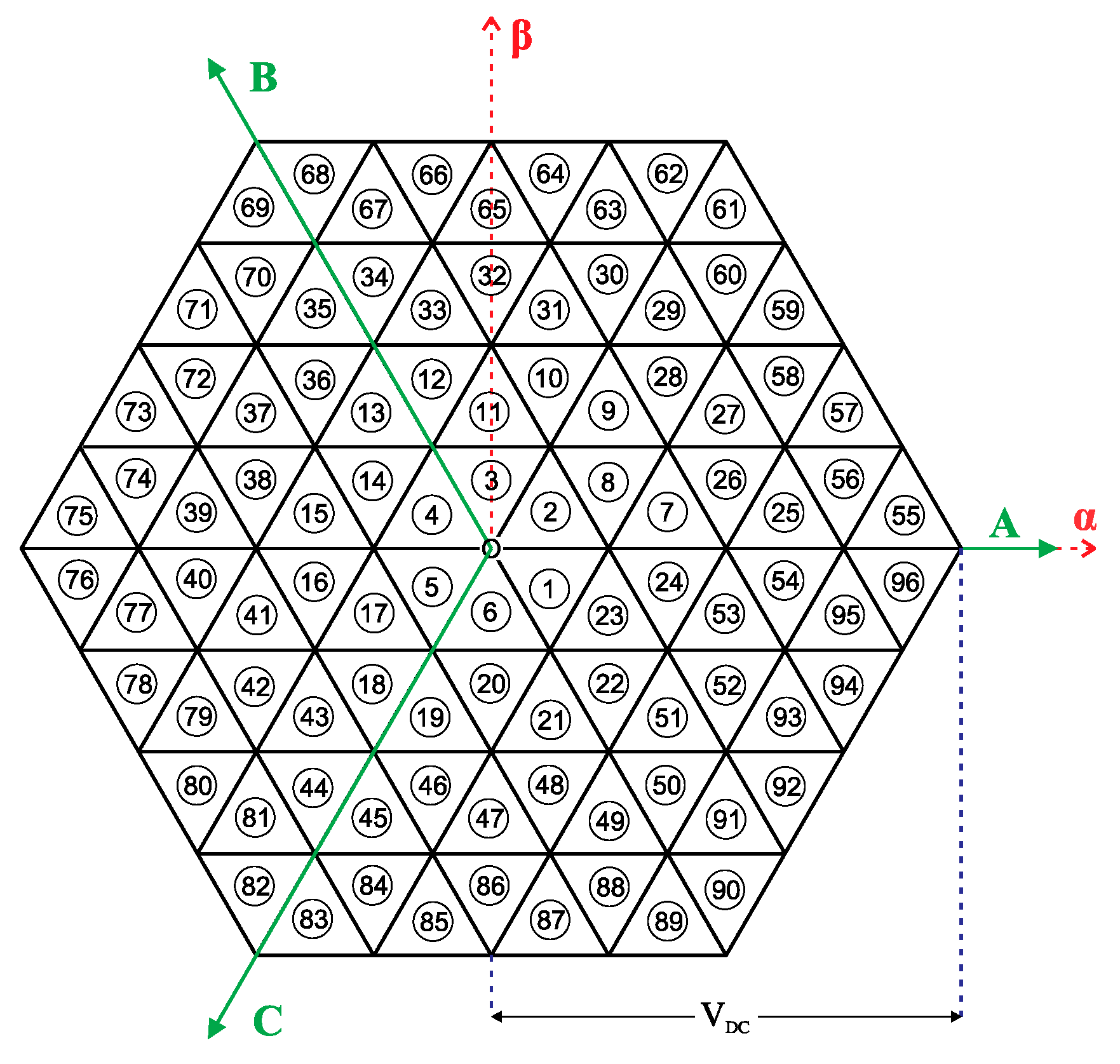
In the proposed power converter topology (see Figure 1), each inverter (1, 2, 3, and 4) can produce a total of eight voltage vectors associated with eight switching states, which are presented in Table 1. In this table, switching states 1…6 are active voltage vectors, whereas states 0 and 7 are zero vectors. Considering all the possible switching state combinations of the four individual inverters, there is a total of 4096 possible voltage vectors in the topology. In general, an output voltage vector can be expressed as:
V o = V A + a V B + a 2 V C
with a = e j 2 π 3 , and V A , V B , and V C are the machine phase voltages given by:
V A = V A 2 V A 4   ,   V B = V B 2 V B 4   ,   V C = V C 2 V C 4
where V A 2 , V B 2 , V C 2 and V A 4 , V B 4 , V C 4 , are the corresponding pole voltages of inverters 2 and 4, respectively. By applying (1) to all the possible switching states, the 4096 voltage vector combinations can be grouped into 61 space locations and form a hexagon that can be divided into 96 sectors (Figure 2).

2.2. Common-Mode Voltage

In the open-end winding machine drive in Figure 1, the common-mode voltage is given by [8]:
V C M = 1 6 ( V A 2 + V B 2 + V C 2 + V A 4 + V B 4 + V C 4 )
If Equation (3) is evaluated with the voltage produced by all the available voltage vectors of the proposed topology, for certain vectors (61 in total), V C M = 0 , thereby eliminating the generation of common-mode voltage at the machine terminals. The switching states that do not produce common-mode voltages in the proposed topology are presented in Table 2.

3. Machine Model

The conventional model of a squirrel cage induction machine consists of a stator and rotor magnetic flux equations [36]. In the α β reference frame, the model is given by:
d Ψ s α β ( t ) d t = u s α β ( t ) R s i s α β ( t )  
d Ψ r α β ( t ) d t = j ω r ( t ) Ψ r α β ( t ) R r i r α β ( t )  
where u s α β is the stator voltage, Ψ s α β and i s α β are the stator magnetic flux and current, respectively, Ψ r α β and i r α β are the rotor magnetic flux and current, respectively, and ω r is the electrical angular speed of the rotor. On the other hand, the machine magnetic fluxes and currents are related by:
Ψ s α β = L s i s α β ( t ) + L 0 i r α β ( t )  
Ψ r α β ( t ) = L 0 i s α β ( t ) + L r i r α β ( t )
where L 0 is the mutual inductance, and L s and L r are the stator and rotor inductances, respectively. By combining Equations (4)–(7), the machine model can be obtained in terms of the stator current and the rotor magnetic flux as follows:
d i s α β ( t ) d t = 1 σ L s [ u s α β   ( t ) + L 0 L s ( R r L r j ω r ( t ) ) Ψ r α β ( t ) ( R s + L 0 2 R r L r 2 ) i s α β ( t ) ]  
d Ψ r α β ( t ) d t = ( R r L r j ω r ( t ) ) Ψ r α β ( t ) + L 0 R r L r i s α β ( t )  
where σ = L r L s L 0 2 L s L r is the total leakage coefficient of the machine. By separating (8)–(9) into real ( α ) and imaginary ( β ) components, the following are obtained:
d i s α ( t ) d t = 1 σ L s [ u s α   ( t ) + L 0 L s ( R r L r Ψ r α ( t ) + ω r ( t ) Ψ r β ( t ) ) ( R s + L 0 2 R r L r 2 ) i s α ( t ) ]  
d i s β ( t ) d t = 1 σ L s [ u s β   ( t ) + L 0 L s ( R r L r Ψ r β ( t ) ω r ( t ) Ψ r α ( t ) ) ( R s + L 0 2 R r L r 2 ) i s β ( t ) ]  
d Ψ r α ( t ) d t = ( R r L r Ψ r α ( t ) ω r ( t ) Ψ r β ( t ) ) + L 0 R r L r i s α ( t )  
d Ψ r β ( t ) d t = ( R r L r Ψ r β ( t ) ω r ( t ) Ψ r α ( t ) ) + L 0 R r L r i s β ( t )  
The presented model is used in the proposed predictive control strategy described in the next section.

4. Predictive Control Strategy

To apply a predictive control scheme, a discrete model of the machine is required. If the sampling period T s is low enough compared to the dynamics of the system, the derivative of the current can be approximated with good accuracy by Euler’s formula   d x d t x [ k + 1 ] x [ k ] T s . Then, the dynamic model of the machine can be rewritten as:
i s α [ k + 1 ] = T s σ L s [ u s α [ k ] + L 0 L s ( R r L r Ψ r α [ k ] + ω r [ k ] Ψ r β [ k ] ) ( R s + L 0 2 R r L r 2 σ L s T s ) i s α [ k ] ]  
i s β [ k + 1 ] = T s σ L s [ u s β [ k ] + L 0 L s ( R r L r Ψ r β [ k ] ω r [ k ] Ψ r α [ k ] ) ( R s + L 0 2 R r L r 2 σ L s T s ) i s β [ k ] ]  
Ψ r α [ k + 1 ] = T s [ ( 1 T s R r L r ) Ψ r α [ k ] ω r [ k ] Ψ r β [ k ] + L 0 R r L r i s α [ k ] ]  
Ψ r β [ k + 1 ] = T s [ ( 1 T s R r L r ) Ψ r β [ k ] + ω r [ k ] Ψ r α [ k ] + L 0 R r L r i s β [ k ] ]  
where x [ k ] represents a variable (voltage, current, or flux) in the current sampling instant and x [ k + 1 ] represents a variable in the next sampling instant. For the sake of simplicity, the rotor speed is assumed to be constant within a sampling period since its variation is very slow compared to the dynamics of the machine’s electrical variables.
With this set of equations, it is possible to predict the future value (instant k + 1 ) of the machine currents and fluxes. For the currents, Equations (15) and (16) are evaluated for all the voltage vectors of the power inverter that do not produce a CMV (Table 2). Therefore, a cost function can be proposed to calculate the error between current references and their predictions:
g = ( i s , r e f α i s α [ k + 1 ] ) 2 + ( i s , r e f β i s β [ k + 1 ] ) 2
The objective is to select the switching state that minimizes this cost function. In general, this form of cost (or objective) function is the simplest possible form when using MPC. However, a larger predictive horizon and/or penalty on the change of the control input to regulate the average switching frequency could be included [37]. The proposed control scheme is shown in Figure 3, where an outer speed-control loop generates a q-axis current reference (associated with the torque) for the machine.

5. Simulation Results

The proposed topology and control strategy were simulated in the PSim platform and the results were then plotted and analyzed in MATLAB. Different torque and speed conditions were considered. The simulation parameters are shown in Table 3.
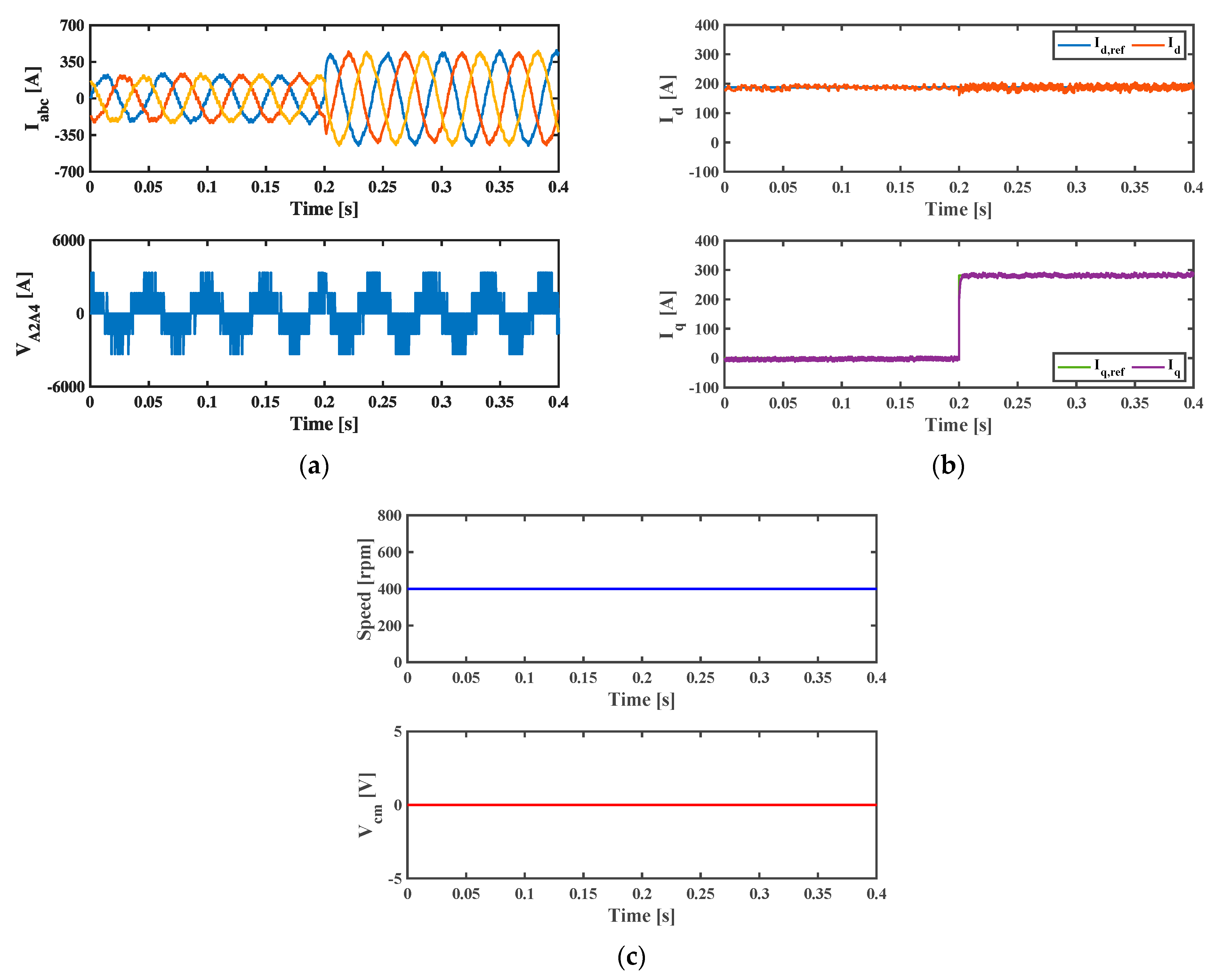
The first test was carried out to verify the performance of the current controllers considering a constant speed of 400 rpm. In this simulation, an initial speed was applied to the PSim induction machine model and the inertia coefficient was set to a high value to avoid speed variations during the current transients. A step change in the q-axis reference current from 0 to ~300 A was applied in t = 0.2 s. The d-axis reference current was kept constant at ~200 A. The results are presented in Figure 4. In Figure 4a, the machine currents and phase-A voltage are shown. The high-quality currents and five-level nature of the voltage can be seen. In Figure 4b, the correct tracking of the reference currents can be observed in the dq reference frame. Figure 4c shows the speed that remained constant during the test and the common-mode voltage at the machine terminals that was eliminated due to the specific set of vectors used in the predictive control algorithm.
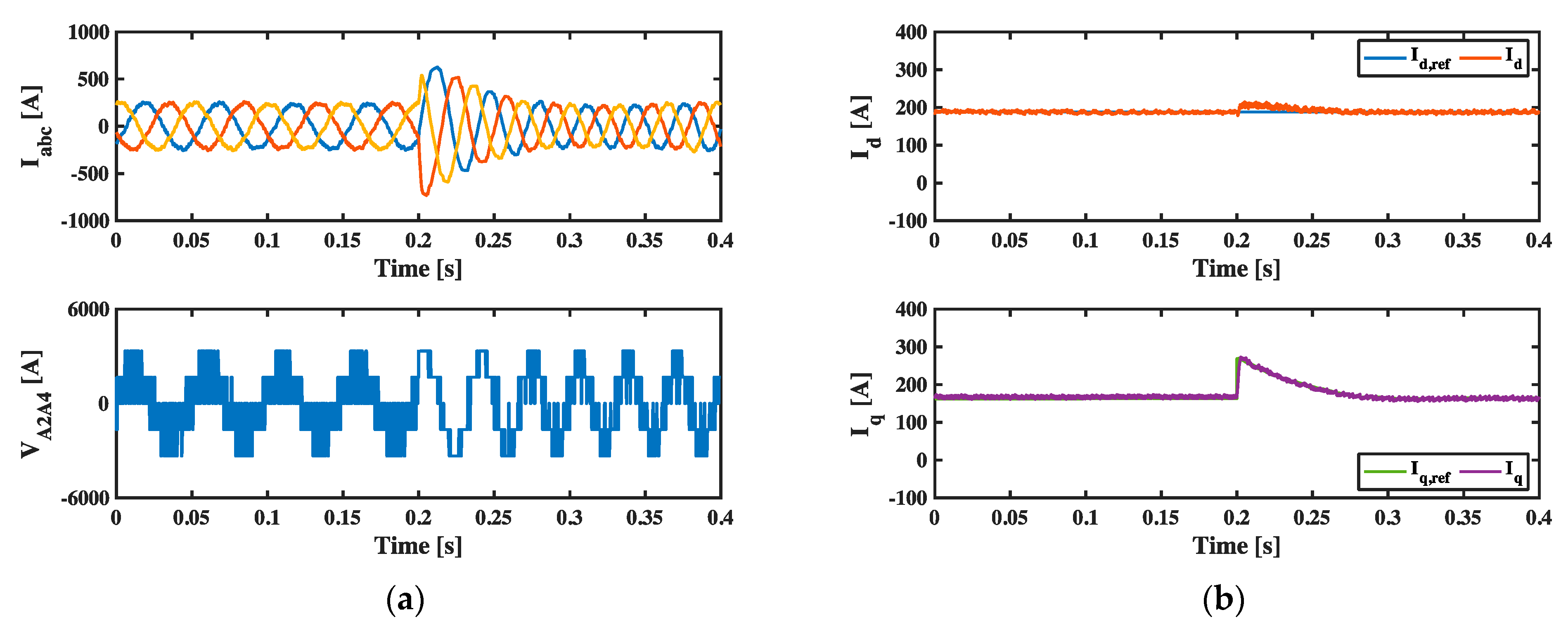
In the second test, the control system was evaluated for constant torque and a step change in the speed applied at t = 0.2 s. The results are shown in Figure 5. Figure 5a shows the currents and phase voltage of the machine. Figure 5b shows the correct tracking of the dq-axis reference currents, whereas Figure 5c shows the machine speed and common-mode voltage. In general, the fast response of the control scheme was achieved with low distortion in the currents and the elimination of the common-mode voltage.
A comparison of MPC and SPWM for the total harmonic distortion (THD) of the machine currents and the torque ripple was carried out for different speeds considering a constant torque of 0.5 pu. Figure 6a shows the current THD, whereas Figure 6b shows the torque ripple. It can be seen that the performance achieved using MPC was similar to that obtained using SPWM, especially at high speeds. The maximum difference between both methods was 1% for the current THD and 1.8% for the torque ripple, thereby making the MPC strategy competitive for the proposed machine drive topology.
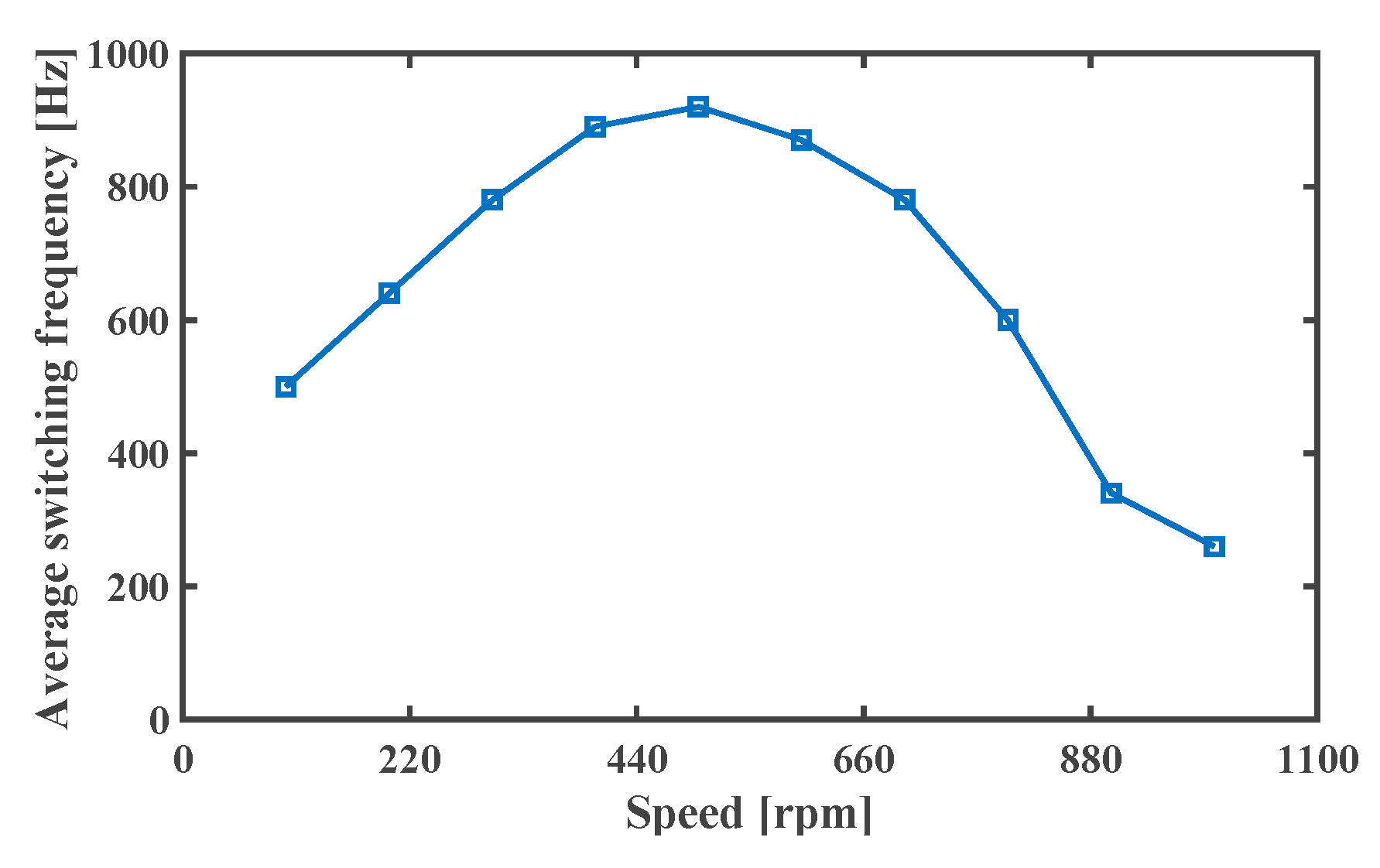
In an MPC strategy, the switching frequency is not constant but could vary depending on the optimization of the cost function (e.g., the same voltage vector selected and applied during two consecutive sampling periods will reduce the equivalent switching frequency). Figure 7 shows the average switching frequency obtained as a function of the speed.
Finally, regarding the losses obtained using the proposed topology and control strategy, a brief efficiency analysis was carried out, again considering the variable speed with a rated constant torque. It is worth mentioning that the losses of the inverter were calculated using a well-accepted method [38] that considers simulated waveform data together with the power device manufacturer’s datasheet information (IGBT Semikron SKM300GA12T4, in this case) to calculate the conduction and switching losses. The obtained efficiency curve is plotted in Figure 8, which shows that a maximum efficiency of about 95% was obtained for the inverter.

6. Conclusions

A predictive control strategy for an open-end winding machine drive was proposed for medium-voltage applications. The power converter topology consists of a multilevel inverter based on cascaded two-level three-phase inverters. The application of a predictive control scheme avoids the employment of complex modulation algorithms typically used in multilevel inverters. Moreover, a reduction in the common-mode voltage at the machine terminals is obtained since the predictive strategy only considers the voltage vectors of the inverter that do not produce a CMV. The simulation results were presented, showing the feasibility of the proposed topology and control strategy. Future work on this topic could include a modification of the proposed topology considering a single DC supply (instead of isolated DC sources) and/or using a modulated model predictive control scheme that combines the benefits of conventional MPC with the advantages of a modulation strategy.

Author Contributions

Conceptualization, J.R., W.J. and R.P.; methodology, J.R. and P.C.; software, P.C., J.R. and I.A.; validation, J.R. and C.P.; formal analysis, P.C. and R.P.; investigation, P.C. and I.A.; writing—original draft preparation, P.C. and J.R.; writing—review and editing, P.C., J.R., W.J., C.P., I.A. and R.P.; supervision, J.R. and W.J. All authors have read and agreed to the published version of the manuscript.

Funding

This research was funded by ANID FONDAP 15110019—PUENTE 1522A0006.

Conflicts of Interest

The authors declare no conflict of interest.

References

  1. ABB Medium Voltage AC Drives. Available online: https://new.abb.com/drives/medium-voltage-ac-drives (accessed on 2 December 2022).
  2. Danfoss Medium Voltage Drives. Available online: https://www.danfoss.com/en-gb/products/dds/medium-voltage-drives/ (accessed on 2 December 2022).
  3. Siemens Medium Voltage Converters. Available online: https://new.siemens.com/global/en/products/drives/sinamics/medium-voltage-converters.html (accessed on 2 December 2022).
  4. Rodriguez, J.; Cortés, P.; Silva, C.; Pontt, J. A New Modulation Method to Reduce Common-Mode Voltages in Multilevel Inverters. IEEE Trans. Ind. Appl. 2004, 51, 834–839. [Google Scholar] [CrossRef]
  5. Do, D.-T.; Nguyen, M.-K.; Ngo, V.-T.; Quach, T.-H.; Tran, V.-T. Common Mode Voltage Elimination for Quasi-Switch Boost T-Type Inverter Based on SVM Technique. Electronics 2020, 9, 76. [Google Scholar] [CrossRef] [Green Version]
  6. Srinivasan, P.; Reddy, B.V.; Somasekhar, V.T. PWM switching strategy for the elimination of common mode voltage of a two-level inverter drive with an open-end winding induction motor configuration. In Proceedings of the 2010 Joint International Conference on Power Electronics, Drives and Energy Systems & 2010 Power India, Delhi, India, 20–23 December 2010; pp. 1–6, 20–23. [Google Scholar]
  7. Jauanne, A.; Zhang, H. A dual-bridge inverter approach to eliminating common-mode voltages and bearing and leakage currents. Trans. Power Electron. 1999, 14, 43–48. [Google Scholar] [CrossRef]
  8. Riedemann, J.; Clare, J.C.; Wheeler, P.W.; Blasco-Gimenez, R.; Rivera, M.; Peña, R. Open-End Winding Induction Machine Fed by a Dual-Output Indirect Matrix Converter. IEEE Trans. Ind. Electron. 2016, 63, 4118–4128. [Google Scholar] [CrossRef]
  9. Edpuganti, A.; Rathore, A.K. Optimal Pulsewidth Modulation for Common-Mode Voltage Elimination Scheme of Medium-Voltage Modular Multilevel Converter-Fed Open-End Stator Winding Induction Motor Drives. IEEE Trans. Ind. Electron. 2016, 64, 848–856. [Google Scholar] [CrossRef]
  10. Teng, J.; Sun, X.; Zhang, Y.; Fu, H.; Liu, X.; Zhao, W.; Li, X. Two Types of Common-Mode Voltage Suppression in Medium Voltage Motor Speed Regulation System Based on Solid State Transformer with Dual DC Bus. IEEE Trans. Power Electron. 2022, 37, 7082–7099. [Google Scholar] [CrossRef]
  11. Deng, Y.; Wang, Y.; Teo, K.H.; Harley, R.G. A Simplified Space Vector Modulation Scheme for Multilevel Converters. Trans. Power Electron. 2016, 31, 1873–1886. [Google Scholar] [CrossRef]
  12. Gu, X.; Wei, B.; Zhang, G.; Wang, Z.; Chen, W. Improved Synchronized Space Vector PWM Strategy for Three-Level Inverter at Low Modulation Index. Electronics 2019, 8, 1400. [Google Scholar] [CrossRef] [Green Version]
  13. Choi, S.; Meliopoulos, A.P. Space Vector Modulation (SVM)-exploited Binary Capacitor Voltage Control (BCVC)-based Flying-Capacitor-Clamped Multilevel Converter (FCCMC) for Low Nominal DC Voltage Applications. In Proceedings of the 2021 22nd IEEE International Conference on Industrial Technology (ICIT), Valencia, Spain, 10–12 March 2021; pp. 488–493. [Google Scholar]
  14. Rodriguez, J.; Cortés, P. Predictive Control of Inductions Machines. In Predictive Control of Power Converters and Electrical Drives, 1st ed.; John Wiley & Sons: New York, NY, USA, 2012; pp. 116–132. [Google Scholar]
  15. Wang, F.; Li, S.; Mei, X.; Xie, W.; Rodríguez, J.; Kennel, R.M. Model-Based Predictive Direct Control Strategies for Electrical Drives: An Experimental Evaluation of PTC and PCC Methods. IEEE Trans. Ind. Inform. 2015, 11, 671–681. [Google Scholar] [CrossRef]
  16. Hammoud, I.; Hentzelt, S.; Oehlschlagel, T.; Abdelrahem, M.; Hackl, C.; Kennel, R. On Continuous-Set Model Predictive Control of Permanent Magnet Synchronous Machines. IEEE Trans. Power Electron. 2022, 37, 10360–10371. [Google Scholar] [CrossRef]
  17. Wang, Q.; Rivera, M.; Riveros, J.A.; Wheeler, P. Modulated Model Predictive Current Control for PMSM Operating With Three-level NPC Inverter. In Proceedings of the 2019 15th IEEE Brazilian Power Electronics Conference and 5th IEEE Southern Power Electronics Conference (COBEP/SPEC), Santos, Brazil, 1–4 December 2019; pp. 1–5. [Google Scholar]
  18. Du, S.; Wu, B.; Tian, K.; Zargari, N.R.; Cheng, Z. An Active Cross-Connected Modular Multilevel Converter (AC-MMC) for a Medium-Voltage Motor Drive. IEEE Trans. Ind. Electron. 2016, 63, 4707–4717. [Google Scholar] [CrossRef]
  19. Du, S.; Wu, B.; Zargari, N.R.; Cheng, Z. A Flying-Capacitor Modular Multilevel Converter for Medium-Voltage Motor Drive. IEEE Trans. Power Electron. 2017, 32, 2081–2089. [Google Scholar] [CrossRef]
  20. Kumar, Y.S.; Poddar, G. Control of Medium-Voltage AC Motor Drive for Wide Speed Range Using Modular Multilevel Converter. IEEE Trans. Ind. Electron. 2017, 64, 2742–2749. [Google Scholar] [CrossRef]
  21. Kumar, Y.S.; Poddar, G. Medium-Voltage Vector Control Induction Motor Drive at Zero Frequency Using Modular Multilevel Converter. IEEE Trans. Ind. Electron. 2018, 65, 125–132. [Google Scholar] [CrossRef]
  22. Titus, J.; Hatua, K. An Induction Machine with Tapped Stator Windings for LCI-Fed Medium Voltage Drive Applications. IEEE Trans. Ind. Electron. 2020, 67, 7217–7227. [Google Scholar] [CrossRef]
  23. Chen, X.; Wang, X.; Kong, M.; Li, Z. Design of a Medium-Voltage High-Power Brushless Doubly Fed Motor With a Low-Voltage Fractional Convertor for the Circulation Pump Adjustable Speed Drive. IEEE Trans. Ind. Electron. 2022, 69, 7720–7732. [Google Scholar] [CrossRef]
  24. Geyer, T. A Comparison of Control and Modulation Schemes for Medium-Voltage Drives: Emerging Predictive Control Concepts Versus PWM-Based Schemes. IEEE Trans. Ind. Appl. 2011, 47, 1380–1389. [Google Scholar] [CrossRef]
  25. Laczynski, T.; Mertens, A. Predictive Current Controller for Inverter Fed Medium Voltage Drives with LC Filter. In Proceedings of the 2007 7th International Conference on Power Electronics and Drive Systems, Bangkok, Thailand, 27–30 November 2007; pp. 1496–1501. [Google Scholar]
  26. Laczynski, T.; Mertens, A. Predictive Stator Current Control for Medium Voltage Drives with LC Filters. IEEE Trans. Power Electron. 2009, 24, 2427–2435. [Google Scholar] [CrossRef]
  27. Yaramasu, V.; Wu, B. Predictive Control of a Three-Level Boost Converter and an NPC Inverter for High-Power PMSG-Based Medium Voltage Wind Energy Conversion Systems. IEEE Trans. Power Electron. 2014, 29, 5308–5322. [Google Scholar] [CrossRef]
  28. Narimani, M.; Wu, B.; Yaramasu, V.; Cheng, Z.; Zargari, N.R. Finite Control-Set Model Predictive Control (FCS-MPC) of Nested Neutral Point-Clamped (NNPC) Converter. IEEE Trans. Power Electron. 2015, 30, 7262–7269. [Google Scholar] [CrossRef]
  29. Dekka, A.; Wu, B.; Yaramasu, V.; Zargari, N.R. Model Predictive Control With Common-Mode Voltage Injection for Modular Multilevel Converter. IEEE Trans. Ind. Inform. 2017, 32, 1767–1778. [Google Scholar] [CrossRef]
  30. Nguyen, M.H.; Kwak, S. Predictive Nearest-Level Control Algorithm for Modular Multilevel Converters with Reduced Harmonic Distortion. IEEE Access 2020, 9, 4769–4783. [Google Scholar] [CrossRef]
  31. Xia, L.; Chen, Z.; Yang, Q.; Xu, L.; Bao, S.; Wu, B. Research on Grid-side Control for a Medium Voltage Direct-Connected Cascaded Inverter Based on Model Predictive Control Under Weak Grid Conditions. In Proceedings of the 2021 IEEE 16th Conference on Industrial Electronics and Applications (ICIEA), Chengdu, China, 1–4 August 2021; pp. 627–632. [Google Scholar]
  32. Somasekhar, V.T.; Gopakumar, K. Three-level inverter configuration cascading two two-level inverters. IEE Proc.-Electic Power Appl. 2003, 150, 245–254. [Google Scholar] [CrossRef] [Green Version]
  33. Baiju, M.R.; Mohapatra, K.K.; Somasekhar, V.T.; Gopakumar, K.; Umanand, L. A five-level inverter voltage space phasor generation for an open-end winding induction motor drive. In Proceedings of the Eighteenth Annual IEEE Applied Power Electronics Conference and Exposition, Miami Beach, FL, USA, 9–13 February 2003; pp. 826–832. [Google Scholar]
  34. Nabae, A.; Takahashi, I.; Agaki, H. A new neutral-point clamped PWM inverter. IEEE Trans. Ind. Appl. 1981, 17, 518–523. [Google Scholar] [CrossRef]
  35. Zhang, G.; Su, Y.; Zhou, Z.; Geng, Q. A Carrier-Based Discontinuous PWM Strategy of NPC Three-Level Inverter for Common-Mode Voltage and Switching Loss Reduction. Electronics 2021, 10, 3041. [Google Scholar] [CrossRef]
  36. Riedemann, J.; Jara, W.; Pesce, C.; Peña, R. Predictive Current Control of an Induction Machine for Solar Pumping Application. In Proceedings of the IEEE International Conference on Automation/XXIII Congress of the Chilean Association of Automatic Control (ICA-ACCA), Concepción, Chile, 17–19 October 2018; pp. 1–5. [Google Scholar]
  37. Karamanakos, P.; Geyer, T. Guidelines for the Design of Finite Control Set Model Predictive Controllers. IEEE Trans. Power Electron. 2020, 35, 7434–7450. [Google Scholar] [CrossRef]
  38. Apap, M.; Clare, J.C.; Wheeler, P.; Bland, M.; Bradley, K. Comparison of losses in matrix converters and voltage source inverters. In IEE Seminar on Matrix Converters, (Digest No 2003/10100); Institution of Engineering and Technology: Birmingham, UK, 2003; pp. 4/1–4/6. [Google Scholar]
Figure 1. Medium-voltage open-end winding induction motor drive.
Electronics 12 01070 g001
Figure 2. Space vector locations of the proposed topology.
Electronics 12 01070 g002
Figure 3. Diagram of the proposed current predictive control strategy for an open-end winding machine drive.
Electronics 12 01070 g003
Figure 4. Simulation results for the constant speed and change in the q-axis current. (a) Machine currents (top) and phase voltage (bottom); (b) dq-axis currents; (c) rotor speed (top) and common-mode voltage (bottom).
Electronics 12 01070 g004
Figure 5. Simulation results for the torque and change in the speed. (a) Machine currents (top) and phase voltage (bottom); (b) dq-axis currents; (c) rotor speed (top) and common-mode voltage (bottom).
Electronics 12 01070 g005aElectronics 12 01070 g005b
Figure 6. Comparison of MPC and SPWM. (a) Current THD as a function of the speed. (b) Torque ripple as a function of the speed.
Electronics 12 01070 g006
Figure 7. Average switching frequency as a function of the speed.
Electronics 12 01070 g007
Figure 8. Inverter efficiency as a function of the speed.
Electronics 12 01070 g008
Table 1. Switching states of the individual three-phase inverters.
Inverter State Nº State   of   Switches   [ S i A   S i B   S i C ]   with   i   =   1 ,   2 ,   3 ,   4 Inverter State Nº State   of   Switches   [ S i A   S i B   S i C ]   with   i   =   1 ,   2 ,   3 ,   4
1 [ 1   0   0 ] 5 [ 0   0   1 ]
2 [ 1   1   0 ] 6 [ 1   0   1 ]
3 [ 0   1   0 ] 7 [ 1   1   1 ]
4 [ 0   1   1 ] 0 [ 0   0   0 ]
Table 2. Voltage vectors for zero common-mode voltages.
Inv.1 StateInv.2 StateInv.3 StateInv.4 State V o Inv.1 StateInv.2 StateInv.3 StateInv.4 State V o
0000 0 0 ° 3303 V D C / 4 120 °
1100 V D C / 2 0 ° 5505 V D C / 4 240 °
4400 V D C / 2 180 ° 2202 V D C / 4 60 °
4411 V D C 180 ° 1133 3 V D C / 2 330 °
1144 V D C 0 ° 3311 3 V D C / 2 150 °
4404 V D C / 4 180 ° 5511 3 V D C / 2 210 °
1101 V D C / 4 0 ° 1155 3 V D C / 2 30 °
4401 3 V D C / 4 180 ° 6637 3 V D C / 4 300 °
1104 3 V D C / 4 0 ° 3306 3 V D C / 4 120 °
3366 V D C 120 ° 5502 3 V D C / 4 240 °
2255 V D C 60 ° 2257 3 V D C / 4 60 °
3300 V D C / 2 120 ° 6605 3 V D C / 4 300 °
0055 V D C / 2 60 ° 2605 3 V D C / 4 120 °
5533 3 V D C / 2 270 ° 4405 7 V D C / 4 100.9 °
3355 3 V D C / 2 90 ° 4403 3 V D C / 4 210 °
6601 3 V D C / 4 270 ° 6602 7 V D C / 4 280.9 °
2201 3 V D C / 4 90 ° 3305 7 V D C / 4 100.9 °
6633 V D C 300 ° 5503 3 V D C / 4 210 °
5522 V D C 240 ° 3354 3 V D C / 4 150 °
6600 V D C / 2 300 ° 1103 7 V D C / 4 340.9 °
5507 V D C / 2 240 ° 4406 3 V D C / 4 120 °
2200 V D C / 2 60 ° 4402 7 V D C / 4 199.1 °
1132 7 V D C / 4 319.1 ° 1105 7 V D C / 4 19.1 °
3301 7 V D C / 4 139.1 ° 1134 13 V D C / 4 346.1 °
5501 7 V D C / 4 220.9 ° 4416 13 V D C / 4 166.1 °
2204 7 V D C / 4 40.9 ° 4412 13 V D C / 4 193.9 °
6632 13 V D C / 4 232.1 ° 1152 3 V D C / 4 330 °
3356 13 V D C / 4 106.1 ° 6632 13 V D C / 4 286.1 °
5532 13 V D C / 4 253.9 ° 3316 13 V D C / 4 133.9 °
2256 13 V D C / 4 73.9 ° 5512 13 V D C / 4 226.1 °
6606 3 V D C / 4 330 °
Table 3. Simulation parameters.
Symbol QuantityValue
V D C DC voltage2000 V
P Power1000 hp
R s Stator resistance0.45 Ω
L s Stator inductance0.0854 H
R s Rotor resistance0.54 Ω
L r Rotor inductance0.086 H
L 0 Magnetizing inductance0.077 H
p Pole pairs6
f s Sampling frequency2 kHz
Disclaimer/Publisher’s Note: The statements, opinions and data contained in all publications are solely those of the individual author(s) and contributor(s) and not of MDPI and/or the editor(s). MDPI and/or the editor(s) disclaim responsibility for any injury to people or property resulting from any ideas, methods, instructions or products referred to in the content.