Communication

Glueless Multiple Input Multiple Output Dielectric Resonator Antenna with Improved Isolation

by
Sumer Singh Singhwal
1,
Ladislau Matekovits
2,3,4,* and
Binod Kumar Kanaujia
5,6
1
Department of Electronics and Communication Engineering, Chandigarh University, Gharuan, Kharar Tehsil 140413, India
2
Department of Electronics and Telecommunications, Politecnico di Torino, 10129 Turin, Italy
3
Department of Measurements and Optical Electronics, Politehnica University Timisoara, 300006 Timisoara, Romania
4
Istituto di Elettronica e di Ingegneria dell’Informazione e delle Telecomunicazioni, National Research Council, 10129 Turin, Italy
5
School of Computational and Integrative Science, Jawaharlal Nehru University, Delhi 110067, India
6
The Department of Electronics & Communication Engineering, Dr. BR Ambedkar National Institute of Technology, Jalandhar 144011, India
*
Author to whom correspondence should be addressed.
Electronics 2023, 12(5), 1125; https://doi.org/10.3390/electronics12051125
Submission received: 18 December 2022 / Revised: 22 February 2023 / Accepted: 23 February 2023 / Published: 25 February 2023
(This article belongs to the Special Issue Disruptive Antenna Technologies Making 5G a Reality)

Abstract

:
In this dissemination, a glueless compact dual port dielectric resonator antenna (DRA) is proposed for X-band applications. A prototype has been fabricated with RT Duroid substrate and Eccostock ( ϵ r = 10)-made DRA. The ring shaped DRA is excited by aperture coupled feeds maintaining symmetry between both the ports. Four cylindrical copper rods with four strips have been used to fix the DRA on the substrate and provide additional mechanical stability. Eight copper strips are used to provide impedance matching and impedance bandwidth (IBW) widening. The measured IBW of dual port DRA is 10.5% (8.05–8.95 GHz) and maximum gain of radiator is 6.2 dBi. The proposed antenna becomes compact when the net volume of DRA is approximately 3.5 cm 3 and the volume of the substrate is 2.88 cm 3 , with a surface area of 36 cm 2 and operating in X-band, which finds applications in satellite communication, weather radar, synthetic aperture radar, and telemetry tracking and control.

1. Introduction

We cannot think of a world without modern wireless communication technologies today. An antenna plays an important role in making communication systems wireless and efficient. Microstrip patch antennas were the preferred choice for major wireless communication applications before the advent of dielectric resonator antennas (DRA). In the current times, the application of dielectric resonator antennas (DRAs) increased in emerging wireless standards because of their inherent advantages, such as no surface wave losses, high radiation efficiency, compact size, nearly constant gain, high impedance bandwidth (IBW), and ease of excitation [1,2,3]. Hence, they are good candidates for various applications across the spectrum, from microwaves to optical frequency bands. The current state of the art of DRAs in the microwave regime includes filtering DRAs [4,5], compact DRAs with omnidirectional radiation patterns [6], RF energy harvesting [7], microwave image sensing [8], directional radiation pattern [9], frequency tunable DRAs [10], X-Band DRA arrays [11], DRAs for 5G communications [12,13], tunable characteristics of DRA [14], DRA in X-band applications [15], and DRA for mm-wave applications [16,17]. Multiple-input multiple-output (MIMO) technology allows us to achieve higher data rates during wireless communication. In MIMO systems, a number of transmitters and receivers are utilized simultaneously to transfer more data, which increases data rates. For this, multiple port antennas are required to act as transmitters and receivers in the wireless system. In [18,19], initial designs of MIMO antenna using DRA, which combines advantages of both MIMO and DRA technology, were presented in 1983. In [20], recent MIMO DRAs have been reviewed comprehensively. Generally, adhesive or glue is used to stick the DRA on the substrate, which gives rise to performance degradation due to an extra layer of glue dielectric between DR and substrate. Radiation properties, impedance matching, and gain of the antenna are also affected due to the application of adhesive [21,22]. Some general-purpose adhesives are Loctite 499 (CyanoAcrylic (CA) type), Loctite 4212, and Araldite, which are used to glue DR with substrates but when high heat is intentionally used for disassembly, the ceramic often cracks before the bond, possibly due to excessive mismatch in the effective expansion rates. These bonds are not very flexible to accommodate differential thermal expansion rates. The bond line has to be carefully process-controlled to minimize RF losses while still preserving mechanical strength.
In recent times, researchers are heading towards achieving glueless techniques in DRA to remove the drawbacks of glue. Compound substrate, grooved ground plane, hooks, and side pins are proposed instead of glue for fixing DRA on the substrate in [23,24,25,26], respectively. As per the knowledge of authors, first time, a novel glueless technique in dual-port MIMO DRA, which not only supports the DRA, but improves its performance, is presented in this dissemination.
Here, an aperture-coupled fed glueless dual port MIMO DRA is presented for X-band applications. Ring shaped cylindrical DRA is taken due to ease of design. Major highlights of proposed antenna are following: (i) compactness; (ii) novel glueless technique; (iii) symmetric structure; and (iv) first glueless dual-port MIMO DRA. The proposed antenna is much more compact than state of art configurations, with net volume of DRA and substrate, which are approximately 3.5 cm 3 and 2.88 cm 3 , respectively. Novel glueless technique with four metallic cylinders are used, which not only provide mechanical strength to the antenna, but improves it performance characteristics also. The antenna demonstrates simulated IBW of 10.37% in X-band with maximum simulated gain of 6.2 dBi. Antenna structure is symmetric, which is a desirable feature in the MIMO antenna for easier installation without any ambiguity regarding ports. MIMO performance parameters, such as total active reflection coefficient (TARC) and envelope correction coefficient ( ρ ), are calculated and measured, and they are found within an acceptable range for MIMO operation. The chosen frequency band is used in high-speed digital radio links in satellite communication and radio communication. The X-band has several applications for example telemetry, satellite tracking, military communication, etc.

2. Antenna Design and Operating Principle

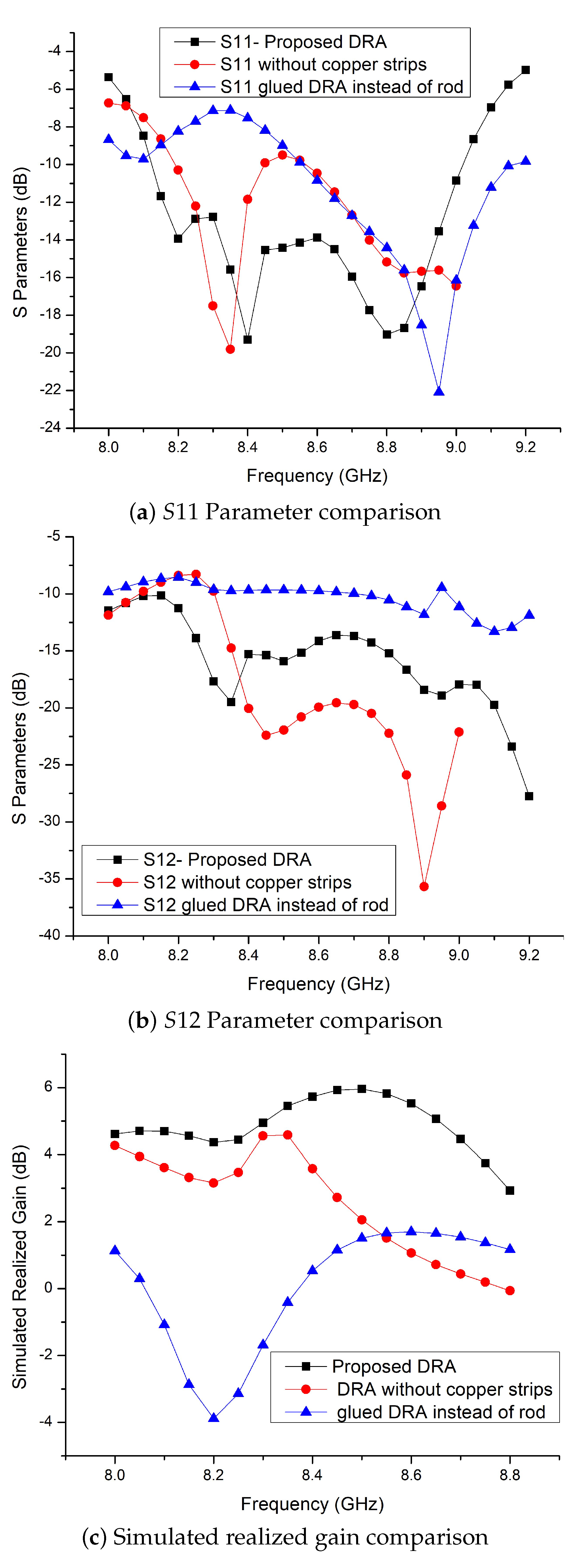
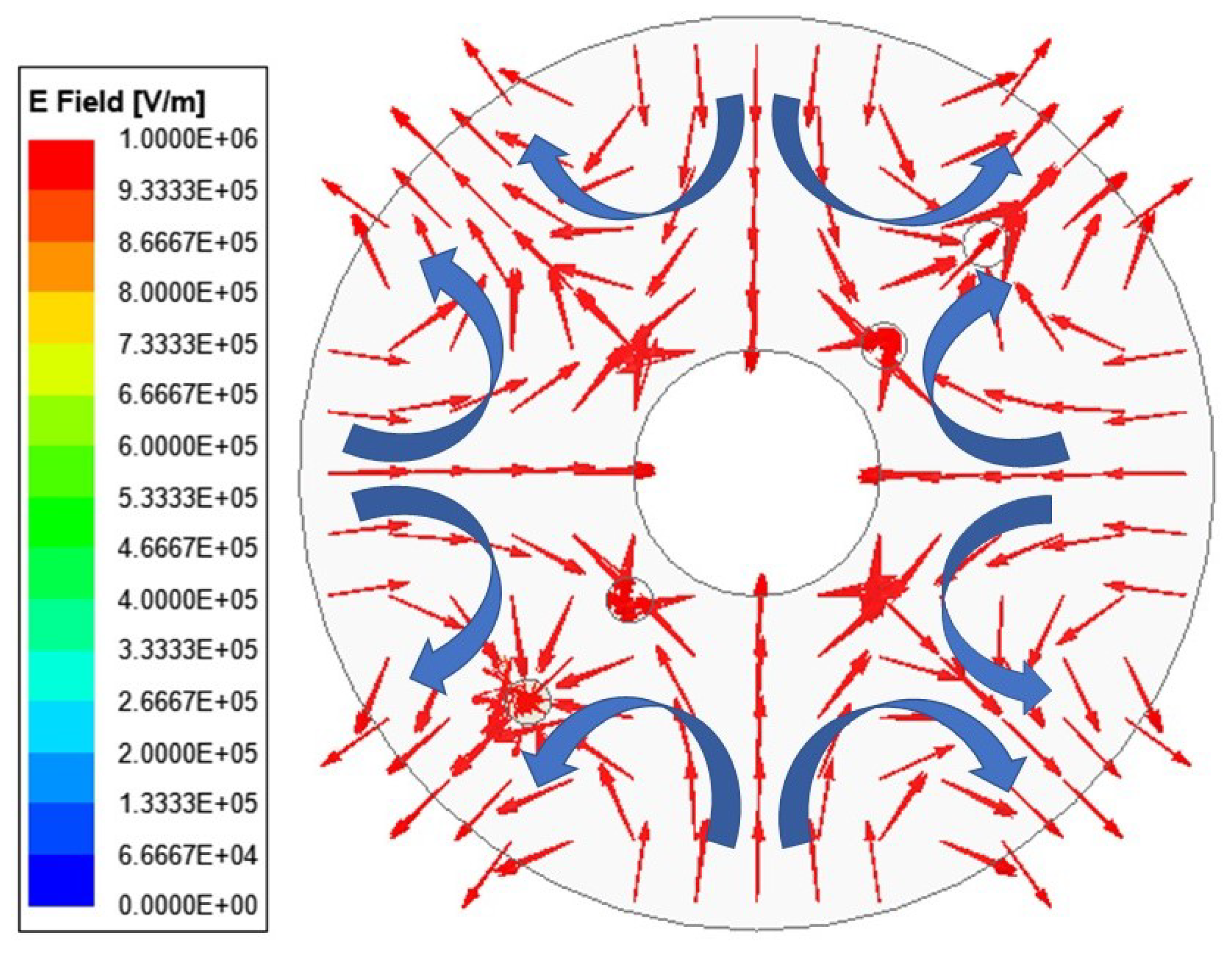
Antenna geometry comprises a substrate, annular ring DRA, four metallic rods, eight copper strips, a defected ground structure, and two microstrip lines as feeds. First guess of dimensions of CDRA for resonant frequency (8.5 GHz) was calculated from design equations mentioned in [1,3]. Insertion of copper rods in CDRA changed its radiation characteristics, which were tuned by performing parametric analysis in the commercially available electromagnetic solver ANSYS HFSS. Geometry of antenna is shown in Figure 1. Rogers RT Duroid 5870 high frequency laminates with dielectric constant ε r = 2.33 , thickness 0.8 mm, and tan δ = 0.0012 has been used as substrate. DRA is constructed with material having electrical properties as ε r = 10 , tan δ = 0.001 . Defected ground structures (DGS) are one of solutions to increase isolation between ports and reduce mutual coupling. Here, DGS is utilized by the introduction of tilted slits in the ground plane. Aperture-coupled feed is used to excite DRA with introduction of 45 titled long slit, which combines both the apertures in the ground plane. Eight copper strips on the surface of DRA are used to enhance gain of antenna. Four copper rods of 1 mm diameter each, have been inserted in the DRA and substrate. These rods are joined by four metallic clips on both sides to provide mechanical stability to DRA, as shown in the Figure 1. Comparison between simulated parameters of three cases: (i) DRA without copper strips; (ii) DRA with glue and copper strips; and (iii) proposed DRA, which is shown in Figure 2. Here, glue is applied in simulation with a 0.1 mm thick bonding film of Rogers R4450B ( ε r = 3.5 , tan δ = 0.004 ) [24]. It is analyzed from Figure 2 that application of glue deteriorates the performance of DRA. Novel mechanism of insertion of thin copper rods not only catapulted the antenna’s performance positively, but also provided desired mechanical stability. These thin rods act as dipoles, which improve radiation characteristics of the antenna at higher-order modes. To dig deep into the modal characteristics of the proposed design, an eigen mode analysis has been done in HFSS. Figure 3 shows simulated E-field of proposed design in the eigen model solver highlighted with arrows, which resembles higher-order TM mode (TM 41 δ ) at 8.8 GHz. It was observed by eigen mode analysis that effect of thin rods become significant at higher order TM modes. However, careful optimization of dimensions and position of metallic rods has been done on EM simulator software (HFSS) to achieve coveted results.

3. Results and Discussion

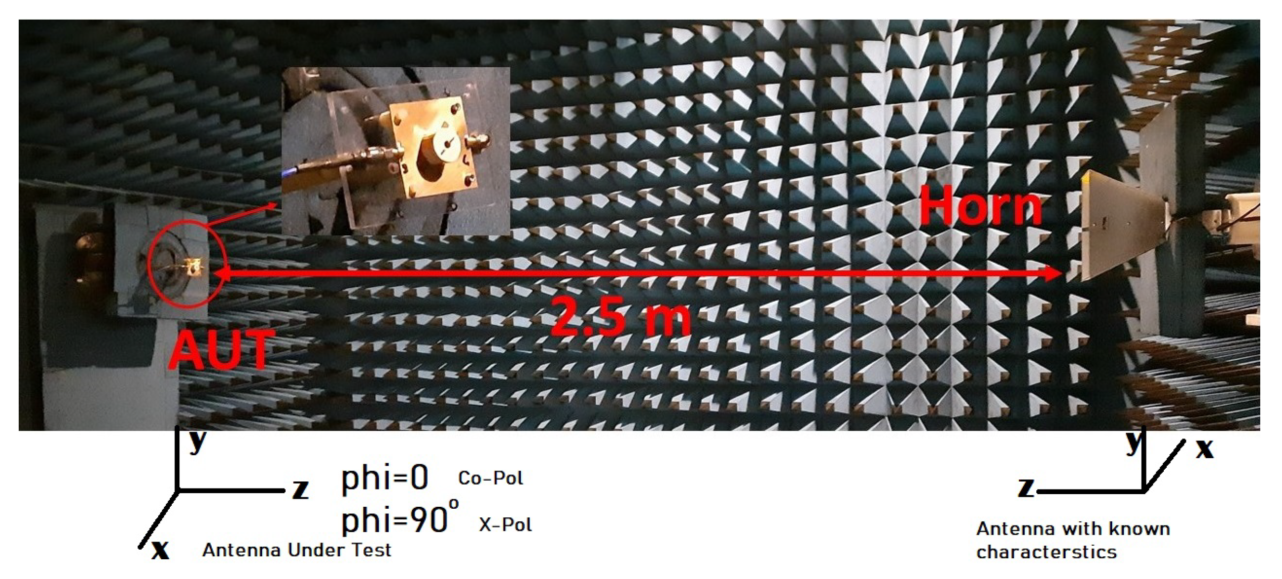
Validation of simulated results can only be done by measuring the results physically. To understand concordance between simulated results and their measured counterparts, a prototype of proposed antenna design has been fabricated, as shown in the inset of Figure 4. This fabrication of prototype has been done manually using standard laboratory tools and insertion of copper rods with highest accuracy, which became an onerous task. Expected tolerance between simulated and measured results may be attributed to manual fabrication process. Measurement of far field results have been accomplished in an anechoic chamber with horn antenna as transmitter antenna and by keeping the other port of the proposed antenna, which has been matched with 50 Ω , as displayed in Figure 4. Cartesian coordinates are also shown in the Figure 4 for the antenna under test and the reference antenna. Angle theta varies are given for 180 to 180 for ϕ = 0 and ϕ = 90 , which provide E-plane and H-plane radiation patterns. Scattering parameters have been measured using Keysight Technologies-N5227A Vector Network Analyzer.
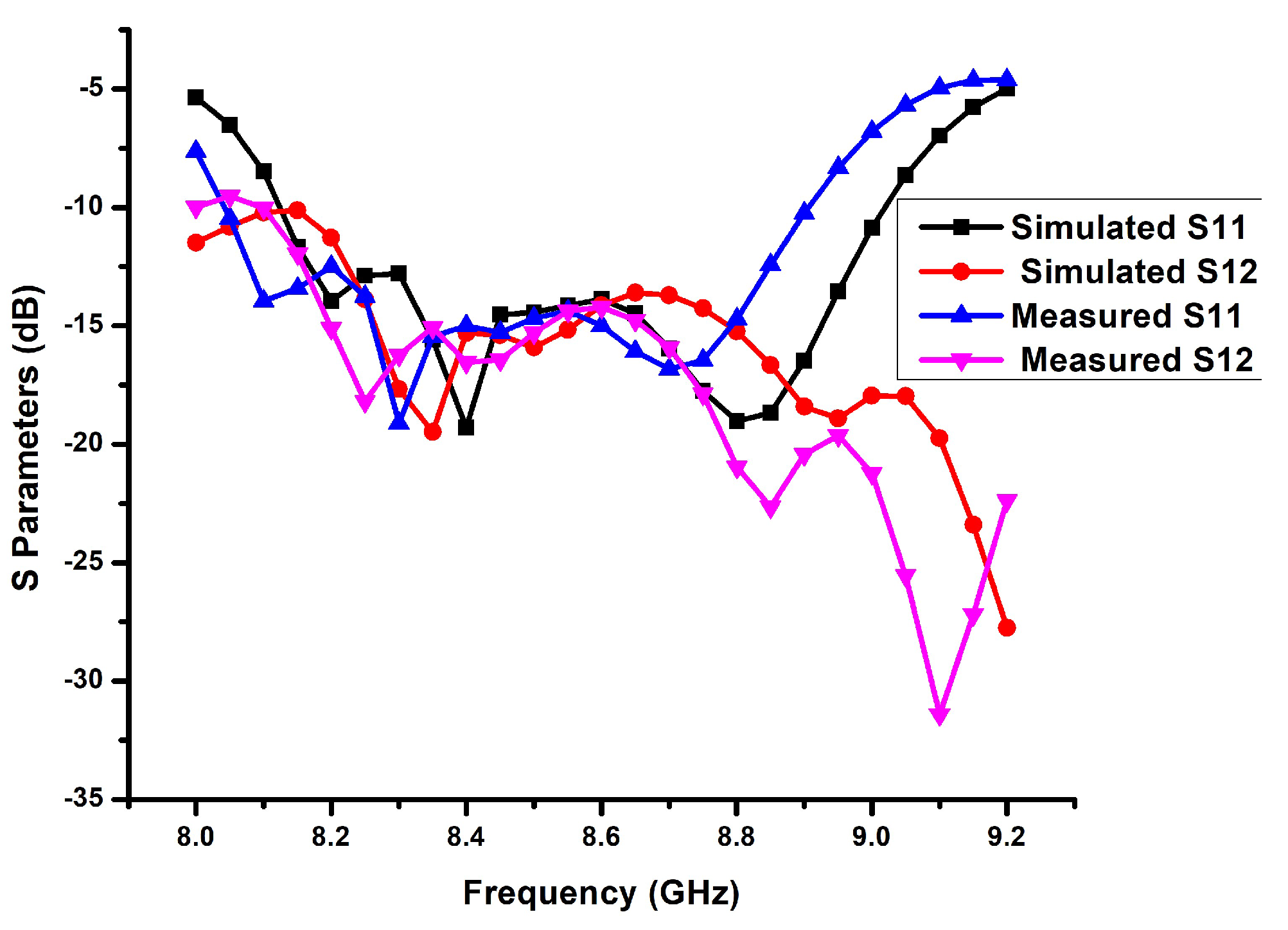
Simulated and measured S−parameters of the proposed MIMO DRA are shown in Figure 5. S 22 identifies with S 11 owing to symmetrical structure of proposed design, hence omitted here for brevity. Simulated and measured radiation patterns for ϕ = 0 and ϕ = 90 of the proposed MIMO DRA at 8.4 GHz are shown in Figure 6. Measured IBW of fabricated prototype is 10.5% (8.05–8.95 GHz), with more than −15 dB isolation (between ports) bandwidth between 8.2–9.2 GHz. It has been perceived that the maximum gain of the proposed DRA is 6.2 dBi, and the simulated radiation efficiency of the antenna is above 0.90, as shown in Figure 7.
For a dual-port MIMO system, ρ is expressed in Equation (1) [12]. ρ describes properties of communication channel with each other, such as isolation and correlation [27]. ρ can be measured using two methods: (i) using S−parameters; and (ii) using radiation pattern. For S−parameters, method radiation efficiencies for each port and at each frequency are also to be computed, which is difficult. It is also found that radiation pattern method of finding ρ is more accurate than the earlier one [8,27,28,29].
ρ 12 = 4 π F 1 ( θ , ϕ ) F 2 ( θ , ϕ ) d Ω 2 4 π F 1 ( θ , ϕ ) 2 d Ω 4 π F 2 ( θ , ϕ ) 2 d Ω
where F i ( θ , ϕ ) is three dimensional field radiation pattern of MIMO antenna when port-i is excited. Ω is solid angle and ∗ represents the product operator. Equation (2) is expanded version of Equation (1).
ρ 12 = 4 π X P R . E θ 1 E θ 2 P θ + E ϕ 1 E ϕ 2 P ϕ d Ω 2 δ 1 . δ 2
where δ for i t h port calculated using Equation (3)
δ i = 4 π X P R . E θ i E θ i P θ + E ϕ i E ϕ i P ϕ d Ω
where E θ 1 and E ϕ 1 are elevation and azimuthal radiated field components for port-1 when other port is matched with 50 Ω termination and similarly for port-2 are E θ 2 and E ϕ 2 . XPR is the cross-polarization discrimination factor, which is the ratio between average power of vertically and horizontally polarized components of the transmitting wave ( X P R = P V / P H ), and represents the complex conjugate.
P θ and P ϕ are angle of arrival power densities for elevation and azimuth directions, respectively, which are represented under following normalization condition:
0 2 π 0 π P θ sin ( θ ) d θ d ϕ = 1 , 0 2 π 0 π P ϕ sin ( θ ) d θ d ϕ = 1
Assume uniform distribution of horizontal and vertical components of incident waves, which is widely considered a case of isotropic environment in rich multipath case, to operate the MIMO system. Take P θ = P ϕ = 1 / ( 4 π ) and P V = P H . Table 1 depicts calculated values of ρ 12 using Equations (1)–(4) and measured far-field radiation components, which are less than 0.3 in the desired frequency band of operation. Simulated values of ρ 12 are not shown here because EM simulator HFSS uses the S−parameter method to compute the correlation coefficient, which comes out less than 0.006 for all frequencies of interest. Low values of ρ confirm the good diversity performance and channel characteristics required for efficient MIMO operation at a higher data rate.
For the dual-port MIMO system, another important MIMO parameter, called TARC, can be calculated using Equation (5) given in [8,27] for different values of angle θ .
T A R C = S 11 + S 12 e j θ 2 + S 21 + S 22 e j θ 2 2
where θ is input feeding phase.
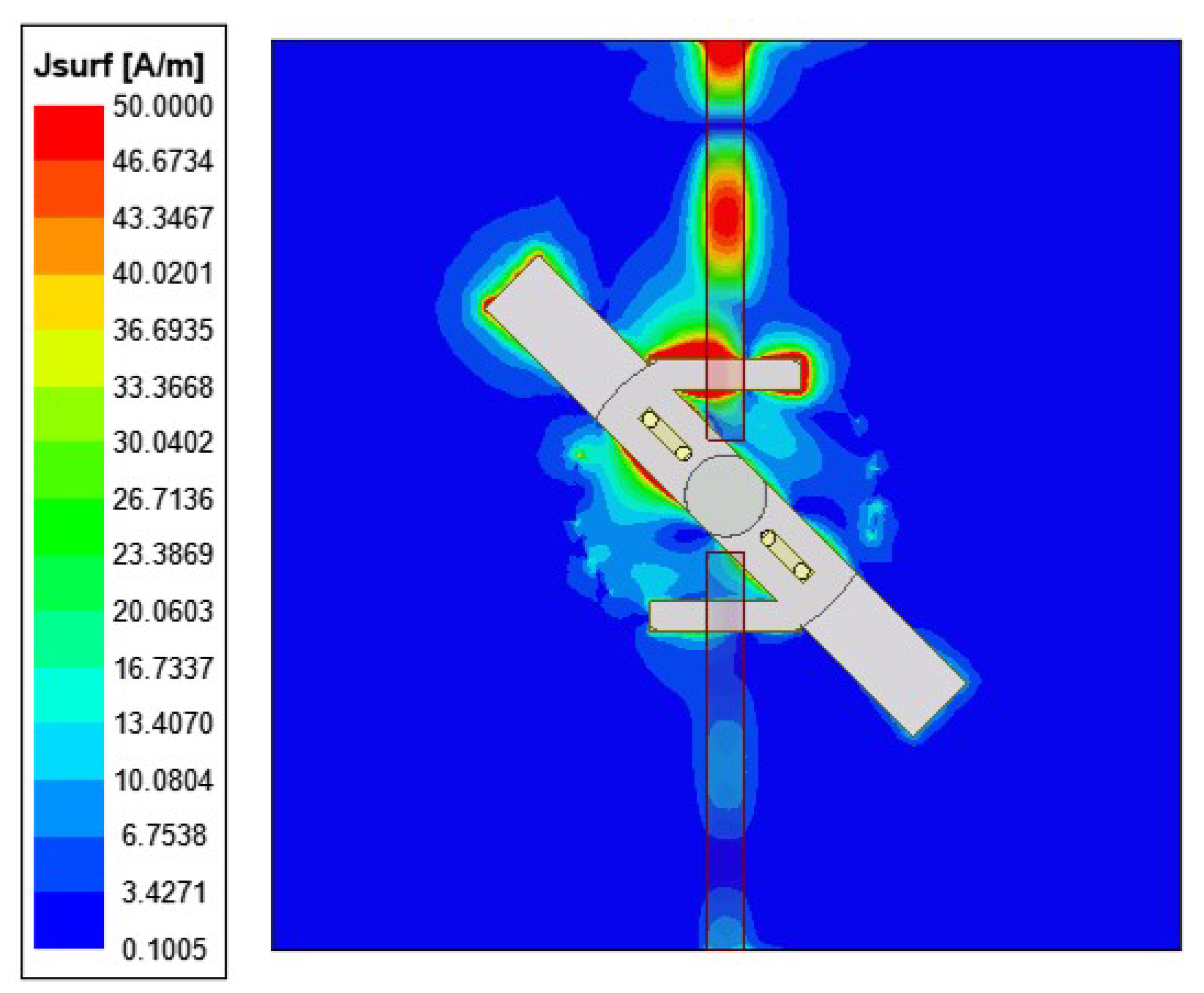
A desirable value of TARC for the MIMO system is less than 0 dB. It is inferred from Figure 8 that TARC is less than −10 dB for all input feeding phase angles in the entire operating frequency range. Surface current distribution of MIMO DRA is shown in Figure 9, which shows minimal mutual coupling between ports. Justifiable performance comparison has been done by including recent single element MIMO DRAs in Table 2. A major highlight of the proposed antenna is its compactness and novel glueless technique to hold the DRA on the substrate.

4. Conclusions

In this dissemination, a glueless MIMO DRA is proposed for X-band applications. Measured IBW of antenna is 10.5% (8.05–8.95 GHz) GHz with maximum gain of 6.2 dBi. A novel technique of insertion of copper rods is proposed, which avoids use of glue between the DRA and the substrate. This technique not only provides greater mechanical strength w.r.t. the glued one, but it also avoids radiation losses due to the insertion of a glue coat between the substrate and the DRA, which makes it competent for higher frequency applications. The proposed antenna shows acceptable MIMO performance, justified by parameters such as ρ and TARC so as to qualify for diverse applications.

Author Contributions

Conceptualization, S.S.S.; methodology, L.M.; investigation, S.S.S., B.K.K. and L.M.; resources, L.M. and B.K.K.; data curation, S.S.S.; writing—original draft preparation, S.S.S.; writing—review and editing, L.M. and B.K.K.; visualization, S.S.S.; supervision, L.M.; project administration, B.K.K.; funding acquisition, L.M. All authors have read and agreed to the published version of the manuscript.

Funding

This research received no external funding.

Institutional Review Board Statement

Not applicable.

Informed Consent Statement

Not applicable.

Data Availability Statement

No data are available.

Conflicts of Interest

The authors declare no conflict of interest.

References

  1. Mongia, R.K.; Bhartia, P. Dielectric resonator antennas—A review and general design relations for resonant frequency and bandwidth. Int. J. RF Microw Millim. Comput.-Aided Eng. 1994, 4, 230–247. [Google Scholar] [CrossRef]
  2. Mongia, R.K.; Ittipiboon, A. Theoretical and Experimental Investigations on Rectangular Dielectric Resonator Antennas. IEEE Trans. Antenna Propag. 1997, 45, 1348–1356. [Google Scholar] [CrossRef]
  3. Luk, K.M.; Leung, K.W. Dielectric Resonator Antennas; Research Studies Press Ltd.: Baldock, UK, 2003. [Google Scholar]
  4. Hu, P.F.; Pan, Y.M.; Zhang, X.Y.; Hu, B.J. A Compact Quasi-Isotropic Dielectric Resonator Antenna With Filtering Response. IEEE Trans. Ant. Propag. 2019, 67, 1294–1299. [Google Scholar] [CrossRef]
  5. Liu, Y.; Leung, K.W.; Ren, J.; Sun, Y. Linearly and Circularly Polarized Filtering Dielectric Resonator Antennas. IEEE Trans. Ant. Propag. 2019, 67, 3629–3640. [Google Scholar] [CrossRef]
  6. Yang, N.; Leung, K.W. Size Reduction of Omnidirectional Cylindrical Dielectric Resonator Antenna Using a Magnetic Aperture Source. IEEE Trans. Ant. Propag. 2020, 68, 3248–3253. [Google Scholar] [CrossRef]
  7. Liu, S.; Yang, D.; Chen, Y.; Huang, S.; Xiang, Y. Broadband Dual Circularly Polarized Dielectric Resonator Antenna for Ambient Electromagnetic Energy Harvesting. IEEE Trans. Ant. Propag. 2020, 68, 4961–4966. [Google Scholar] [CrossRef]
  8. Singhwal, S.S.; Kanaujia, B.K.; Singh, A.; Kishor, J. Novel circularly polarized dielectric resonator antenna for microwave image sensing application. Microw. Opt. Technol. Lett. 2019, 61, 1821–1827. [Google Scholar] [CrossRef]
  9. Singhwal, S.S.; Kanaujia, B.K.; Singh, A.; Kishor, J. Circularly polarized V-shaped dielectric resonator antenna. Int. J. RF Microw. Comput. Aided Eng. 2019, 29, 9. [Google Scholar] [CrossRef]
  10. Hao, C.X.; Li, B.; Leung, K.W.; Sheng, X.Q. Frequency Tunable Differentially Fed Rectangular Dielectric Resonator Antennas. IEEE Antennas Wirel. Propag. Lett. 2011, 10, 884–887. [Google Scholar] [CrossRef]
  11. Movahedinia, R.; Sebak, A.; Chaharmir, M.R.; Ranjbar, N.M.; Kishk, A.A. X-Band Circularly Polarized Electronically Steerable Parasitic Array Radiator of DRA. IEEE Trans. Antennas Propag. 2018, 66, 721–728. [Google Scholar] [CrossRef]
  12. Singhwal, S.S.; Kanaujia, B.K.; Singh, A.; Kishor, J.; Matekovits, L. Multiple Input Multiple Output Dielectric Resonator Antenna with Circular Polarized adaptability for 5G Applications. J. Electromagn. Waves Appl. 2020, 34, 1180–1194. [Google Scholar] [CrossRef]
  13. Singhwal, S.S.; Kanaujia, B.K.; Singh, A.; Kishor, J.; Matekovits, L. Dual-Band Circularly Polarized MIMO DRA for Sub-6 GHz Applications. Int. J. Microw.-Comput.-Aided Eng. 2020, 30, e22350. [Google Scholar] [CrossRef]
  14. Liu, B.; Qiu, J.; Chen, L.; Li, G. Dual Band-Notched Rectangular Dielectric Resonator Antenna with Tunable Characteristic. Electronics 2019, 8, 472. [Google Scholar] [CrossRef] [Green Version]
  15. Khan, S.; Khan, M.A.; Anab, M.; Marwat, S.N.K.; Jan, N.; Ghoniem, R.M. Wideband Singly Fed Compact Circularly Polarized Rectangular Dielectric Resonator Antenna for X-Band Wireless Applications. Electronics 2022, 11, 3281. [Google Scholar] [CrossRef]
  16. Alanazi, M.D.; Khamas, S.K. Wideband mm-Wave Hemispherical Dielectric Resonator Antenna with Simple Alignment and Assembly Procedures. Electronics 2022, 11, 2917. [Google Scholar] [CrossRef]
  17. Huang, R.-Z.; Zhang, J.-W.; Zhang, C. Dual-Band Circularly Polarized Hybrid Dielectric Resonator Antenna for 5G Millimeter-Wave Applications. Electronics 2022, 11, 1761. [Google Scholar] [CrossRef]
  18. Ishimiya, K.; Langbacka, J.; Ying, Z.; Takada, J.I. A compact MIMO DRA antenna. In Proceedings of the International Workshop on Antenna Technology: Small Antennas and Novel Metamaterials, Chiba, Japan, 4–6 March 2008; pp. 286–289. [Google Scholar]
  19. Ishimiya, K.; Ying, Z.; Langbacka, J. A compact MIMO DRA for 802.11n application. In Proceedings of the IEEE Antennas and Propagation Society International Symposium, San Diego, CA, USA, 5–11 July 2008. [Google Scholar] [CrossRef]
  20. Singhwal, S.S.; Matekovits, L.; Kanujia, B.K.; Kishor, J.; Fakhte, S.; Kumar, A. Dielectric Resonator Antennas: Applications and Developments in Multiple-Input, Multiple-Output Technology. IEEE Antenna Propag. Mag. 2022, 64, 26–39. [Google Scholar] [CrossRef]
  21. Faiz, A.M.; Gogosh, N.; Khan, S.A.; Shafique, M.F. Effects of an ordinary adhesive material on radiation characteristics of a dielectric resonator antenna. Microw. Opt. Technol. Lett. 2014, 56, 1502–1506. [Google Scholar] [CrossRef]
  22. Kim, D.; You, C.; Hwang, W. Effect of adhesive bonds on electrical performance in multi-layer composite antenna. Compos. Struct. 2009, 90, 413–417. [Google Scholar] [CrossRef]
  23. Sarkar, C.; Guha, D.; Kumar, C. Glueless Compound Ground Technique for Dielectric Resonator Antenna and Arrays. IEEE Antennas Wirel. Propag. Lett. 2017, 16, 2440–2443. [Google Scholar] [CrossRef]
  24. Boyuan, M.; Pan, J.; Wang, E.; Luo, Y. Fixing and Aligning Methods for Dielectric Resonator Antennas in K Band and Beyond. IEEE Access 2019, 7, 12638–12646. [Google Scholar] [CrossRef]
  25. Sarkar, C.; Kumar, C.; Guha, D. A User-Friendly Glueless Solution for Dielectric Resonator Antennas Using a Probe-Feeding Technique [Antenna Applications Corner]. IEEE Antennas Propag. Mag. 2019, 61, 70–74. [Google Scholar] [CrossRef]
  26. Meher, P.R.; Behera, B.R.; Mishra, S.K. Broadband circularly polarized edge feed rectangular dielectric resonator antenna using effective glueless technique. Microw Opt. Technol. Lett. 2020, 62, 1–9. [Google Scholar] [CrossRef]
  27. Sharawi, M.S. Current Misuses and Future Prospects for Printed Multiple-Input, Multiple-Output Antenna Systems [Wireless Corner]. IEEE Antennas Propag. Mag. 2017, 59, 162–170. [Google Scholar] [CrossRef]
  28. Sharawi, M.; Hassan, A.; Khan, M. Correlation coefficient calculations for MIMO antenna systems: A comparative study. Int. J. Microw. Wirel. Technol. 2017, 9, 1991–2004. [Google Scholar] [CrossRef]
  29. Elshirkasi, A.M.; Al-Hadi, A.A.; Mansor, M.F.; Khan, R.; Soh, P.J. Envelope Correlation Coefficient of a Two-Port MIMO Terminal Antenna Under Uniform and Gaussian Angular Power Spectrum with User’s Hand Effect. Prog. Electromagn. Res. C 2019, 92, 123–136. [Google Scholar] [CrossRef] [Green Version]
  30. Zou, L.; Abbott, D.; Fumeaux, C. Omnidirectional cylindrical dielectric resonator antenna with dual polarization. IEEE Antennas Wirel. Propag. Lett. 2012, 11, 515–518. [Google Scholar] [CrossRef] [Green Version]
  31. Fang, X.S.; Leung, K.W.; Luk, K.M. Theory and Experiment of Three-Port Polarization-Diversity Cylindrical Dielectric Resonator Antenna. IEEE Trans. Ant. Propag. 2014, 62, 4945–4951. [Google Scholar] [CrossRef]
  32. Das, G.; Sharma, A.; Gangwar, R.K. Dual port aperture coupled MIMO cylindrical dielectric resonator antenna with high isolation for WiMAX application. Int. J. Microw.-Comput.-Aided Engg. 2017, 27, e21107. [Google Scholar] [CrossRef]
  33. Sharma, A.; Sarkar, A.; Biswas, A.; Akhtar, M.J. Equilateral triangular dielectric resonator based co-radiator MIMO antennas with dual polarization. IET Microw. Antennas Propag. 2018, 12, 2161–2166. [Google Scholar] [CrossRef]
  34. Guha, D.; Sarkar, C.; Kumar, C. Dielectric resonator antenna: A solution for its mount on metallic body. In Proceedings of the 2017 IEEE International Symposium on Antennas and Propagation and USNC/URSI National Radio Science Meeting, San Diego, CA, USA, 9–14 July 2017; pp. 1765–1766. [Google Scholar] [CrossRef]
  35. Sarkar, C.; Guha, D. Mechanically Stable No Adhesive Approach for Rectangular Dielectric Resonator Antenna: A Commercially Viable Design for Practical Applications. In Proceedings of the 2019 URSI Asia-Pacific Radio Science Conference (AP-RASC), New Delhi, India, 9–15 March 2019; pp. 1–4. [Google Scholar] [CrossRef]
  36. Aqeel, S.; Jamaluddin, M.H.; Khan, A.A.; Khan, R.; Kamarudin, M.R.; Kazim, J.R.; Owais, O. A Dual-Band Multiple Input Multiple Output Frequency Agile Antenna for GPSL1/Wi-Fi/WLAN2400/LTE Applications. Int. J. Antennas Propag. 2016, 2016, 9419183. [Google Scholar] [CrossRef] [Green Version]
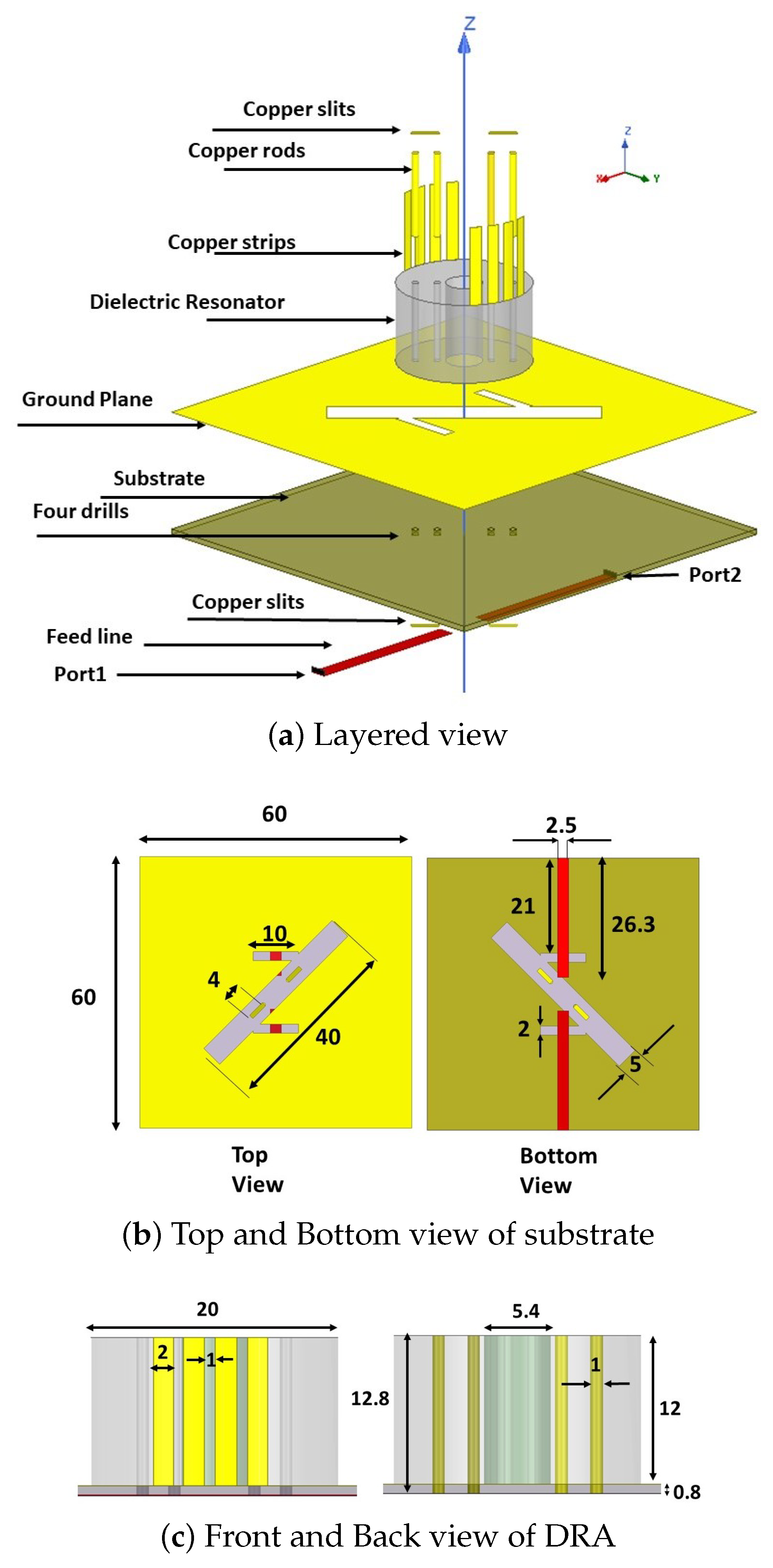
Figure 1. Geometry of proposed Antenna.
Electronics 12 01125 g001
Figure 2. Comparison of simulated S 11 , S 12 and realized gain of different Antennas.
Electronics 12 01125 g002
Figure 3. Simulated E-Field of proposed model in Eigen mode solver at 8.8 GHz. (In scale E Field 1.0000E+06 is 1 × 10 6 V/m).
Electronics 12 01125 g003
Figure 4. Measurement of far field radiation parameters in anechoic chamber.
Electronics 12 01125 g004
Figure 5. Simulated and measured S−parameters of proposed Antenna.
Electronics 12 01125 g005
Figure 6. Simulated and measured radiation pattern of proposed antenna at 8.4 GHz.
Electronics 12 01125 g006
Figure 7. Simulated and measured gain and simulated radiation efficiency of proposed DRA.
Electronics 12 01125 g007
Figure 8. Simulated TARC of MIMO DRA for different values of θ = 0 , 30 , 60 , 90 , 120 , 150 , 180 in Equation (5).
Electronics 12 01125 g008
Figure 9. Surface current distribution at 8.8 GHz.
Electronics 12 01125 g009
Table 1. Measured Envelope Correction Coefficient ( ρ ).
Frequency (GHz)8.38.48.58.68.78.8
ρ 12 0.160.050.170.290.170.04
Table 2. Comparison Table.
Ref.IBW (GHz)Gain (dB)ExcitationIsolation between PortsNo. of PortsGlueless
[23]3.95–4.15.5microstrip linenot applicable1yes, groove and side pin
[25]3.95–4.16Probenot applicable1yes, groove in ground plane
[30]3.78–4.075.1Multiple feed line−162No
[31]2.4–2.512.49Cross aperture coupledNot Given3No
[32]3.1–3.75.1Aperture coupled−252No
[33]5.18–5.835.94Microstrip feed−302No
[34]3.7–4.96Aperture couplednot applicable1yes, compound ground plane
[35]3.35–3.655Aperture couplednot applicable1yes, side metal clamps
[36]1.41–1.49 and 2.2–2.854.83 and 4.92Probe−62No
This work8.2–9.026.2Aperture coupled−142yes, thin copper rods used
Disclaimer/Publisher’s Note: The statements, opinions and data contained in all publications are solely those of the individual author(s) and contributor(s) and not of MDPI and/or the editor(s). MDPI and/or the editor(s) disclaim responsibility for any injury to people or property resulting from any ideas, methods, instructions or products referred to in the content.