Communication

CMOS-Based Memristor Emulator Circuits for Low-Power Edge-Computing Applications

by
Prosenjit Kumar Ghosh
,
Shah Zayed Riam
,
Md Sharif Ahmed
and
Prabha Sundaravadivel
*
Department of Electrical and Computer Engineering, The University of Texas at Tyler, Tyler, TX 75799, USA
*
Author to whom correspondence should be addressed.
Electronics 2023, 12(7), 1654; https://doi.org/10.3390/electronics12071654
Submission received: 30 January 2023 / Revised: 4 March 2023 / Accepted: 20 March 2023 / Published: 31 March 2023

Abstract

:
In this paper, an optimized memristor emulator circuit is designed, by using nine MOSFET transistors and a ground capacitor. Our area- and power-optimized emulator circuit can be used for basic data storage and processing at the monitoring edge, in real-time applications. The memristor shows a nonlinear voltage–current relationship, but no multiplier circuit provides the memristor’s nonlinear characteristics. As a result, the proposed memristor emulator has a very low chip area. The memristor circuit is designed in LTSpice, using 16 nm and 45 nm CMOS technology parameters, and the operating voltage is ±0.9 V. In this research, the theoretical derivations are validated using the simulated results of the memristor emulator circuit using different frequencies, capacitors, and input voltages in SPICE simulations.

1. Introduction

With the high demand for nanoscale devices, the demand for low-power and more compact devices, that can exist on an integrated circuit (IC), is increasing tremendously. Recent technological advancements have facilitated the creation of increasingly small and efficient devices, which are particularly relevant for advanced computing and compact electronics. Surprisingly, current technologies have been surpassing Moore’s law. In recent years, there has been a growing demand for low-power edge-computing systems, that can analyze data at the data acquisition source, rather than transmitting it to a cloud, which makes high-memory devices more desirable. As the adoption of edge computing continues to increase, there is a growing demand for increased computational power, and ongoing research in this area.

1.1. Challenges in Memristor Integration

Memristor technology, and its integration in real-time applications, is still in its early stages of development, and the commercial availability of memristor-based products is limited. Implementation of the memristor is still not cost effective. Due to the complex fabrication process, where precise control is a must, it is also challenging to manufacture. Furthermore, the behavior of memristors can be highly unpredictable and dependent on the material properties and device structure, making it challenging to design reliable and reproducible devices. This has limited the commercial availability of memristors and slowed their integration into mainstream computing systems. Another challenge, is the lack of standardization in the fabrication and characterization of memristors, which hinders the development of standardized protocols and testing procedures. This makes it difficult to compare the performance of memristors across different research groups and manufacturers. Research is ongoing to overcome these challenges. For example, the standardization of the memristor fabrication process, for repetitive production, is feasible for new design implementation and, most importantly, modeling and simulation. Developing accurate models and emulators of memristors could help to predict and understand their behavior, which could aid in designing and optimizing memristor-based devices. Realizing the importance of memristors, researchers have developed CMOS-based memristor emulator circuits, that can simulate the behavior of memristors using conventional CMOS transistors. These emulator circuits offer several advantages over traditional memristor designs, including low power consumption, compatibility with existing CMOS fabrication processes, and scalability for mass production. This type of emulator allows researchers and engineers to simulate and test memristor-based systems without relying on expensive and challenging-to-fabricate physical devices. By using a CMOS-based memristor emulator, it is possible to overcome some of the challenges associated with the fabrication and standardization of memristors and optimize the design and performance of memristor-based circuits and systems. For instance, a CMOS-based memristor emulator circuit is a current-starved inverter circuit (also known as CSI), that can simulate the nonlinear behavior of the memristor resistance [1]. A floating gate transistor (FGT) circuit is another instance that can emulate memristor hysteresis behavior. It is also usable in high-frequency applications [2].

1.2. Applications of Memristors

The unavailability of memristors in the market is due to cost and technical difficulties. The authors propose developing a SPICE memristor model, and introducing a new approach to using CMOS technology with the memristor. An interfacing circuit between the SPICE model and the CMOS circuit is presented, which is crucial for incorporating memristors into CMOS [3]. The study presents a solution to overcome limitations in CMOS transistors by incorporating memristors, and outlines a memristor resistance write circuit and two types of read circuits. The results show that the memristor resistance can be programmed and the current read circuit provides a usable output [4]. The switching ability of memristors is used in logic circuits [5,6], where memristor resistance is represented as logical states. Since memristors can store past states, they can be used to make high-capacity, nonvolatile resistive memory. In addition, the memristor-based memory has fewer noise margins and can store non-binary data [7]. Developing emerging memories, using a memristor, is an attractive research field. Moreover, memristors have recently been applied in various fields. For instance, integrated pixel sensors can use memristors store the pixel data with increased speed processing of signals. Those signals are from the sensor, which also helps to reduce the sensor’s size [8]. Memristors have also been used in: logic circuit development [9], up–down counter design, with fewer transistors [10], full subtractor [11] Programmable Wien Bridge Oscillator [12], nanoscale memristor based 2:1 multiplexer [13], lower power wireless sensors for biomedical applications [14], neuro-memristive circuits for edge computing [15], and different kinds of sensors [8,16,17,18,19]. They are also used in communications and networking [15], the internet of things (IoT) [16], and unmanned aerial vehicles (UAV) [17,18]. Edge computing requires the system to collect, process, and cache the collected data at the monitoring edge [20]. The edge-intelligent systems can range from smart healthcare wearables [21,22], to computer vision applications, where there is a limitation in terms of the connectivity to send the data in real-time. However, effective emulators are required to enable these research activities. They must be simple yet effective, integratable, and operable at low voltage and low power, because technology has shifted towards those aspects. These applications require a large number of memristors.

Memristor Neural Networks

Memristor emulators have a wide range of applications in the field of computing, and one such application is the development of memristive neural networks. Memristive neural networks are artificial neural networks that use memristors as synaptic weights, enabling them to achieve low-power and high-density computing. Memristor emulators enable the simulation and testing of these neural networks without the need for actual memristors, which are still expensive and difficult to fabricate. By using memristor emulators, researchers can develop and optimize memristive neural networks in a cost-effective and practical manner, thus accelerating progress in this field. Another potential application of memristor emulators is in the development of reconfigurable computing systems. Reconfigurable computing systems can adapt to changing computational requirements by reconfiguring their hardware, thereby improving their efficiency and flexibility. Memristor-based circuits have the potential to be used in the development of such systems, as they offer the ability to reconfigure their resistance values based on the input signals. Memristor emulators can be used to simulate and test these circuits, enabling researchers to optimize their design and performance.
Furthermore, memristor fabrication remains challenging, due to highly sophisticated design procedures and cost constraints that limit real-time applications. Although the Knowm memristor [19] is commercially available, there is still room for additional study in this area. The first commercially available memristor in the world was made possible by bio-inspired technologies, which are only appropriate in certain situations, to prevent irreparable harm [23]. Memristor emulators are therefore being created to mimic their characteristics, using analog building blocks, such as second-generation current conveyors (CCII) [24,25], operational transconductance amplifiers (OTA) [26], current feedback operational amplifiers (CFOA) [27], differential difference current conveyors (DDCC) [28], current conveyor transconductance amplifiers (CCTA) [29], current backward transconductance amplifiers (CBTA) [30], and so forth. However, the circuits are complex and use an analog multiplier and several operational amplifiers, resistors, and MOS transistors.

1.3. Memristor for Edge and Neuromorphic Computing Applications

One key element of such systems is a memristor emulator circuit, which mimics the behavior of a memristor, a two-terminal device whose resistance can be controlled and modulated by an applied voltage. Memristors show great potential for low-power computing systems. They have the unique ability to keep data without the requirement for continuous power. This power-saving feature has helped the memristor to attract more researchers and developers to do extensive research in recent years. It also has other advantages such as fast speed, optional continuous power, and more durability, along with its low power consumption. Interestingly, this vital ‘memristor’, was a missing element until 1971. Leon Chua introduced the concept of this basic nonlinear element in a seminal paper in 1971, where he mentioned the relationship between the linear resistor, linear capacitor, and linear inductor. This fourth basic two-terminal device’s properties could not be explained with only RLC networks [31]. However, memristors remained theoretical until Stan William and his team from HP lab realized the first physical memristor model. They showed great analytical instances of how memristance naturally arises in nanoscale systems. This system happened, with an external bias voltage, to show a wide range of hysteric voltage–current behavior [32,33]. This nanodevice, called a memristor, now deemed the fourth fundamental component, features a special I-V pinched hysteresis loop with a switching mechanism, and the capacity to recall its last state. Its low power consumption, nonvolatile nature, and switching capability, have driven memristor application research in CMOS circuit designs [34].
Memristors are used as nonvolatile memory devices [34,35], with high density, and speeds comparable to DRAM, also, in chaotic circuit implementations, and even modeling and simulation of synaptic neurons in neuromorphic computing system research [36]. In neuromorphic computing systems, highly parallel biological systems are implemented as hardware for information processing in an optimized platform. Memristors help in stabilizing the synaptic responses in these dense systems.
This study presents a new memristor emulator circuit, containing only nine transistors and a single grounded capacitor, which can be realized as an integrated circuit (IC) without using any active circuit element, while keeping the focus on the recent advances in CMOS-based memristor emulator circuits for low-power edge-computing applications. The MOS capacitance works as the element that obtains the memory effect of the memristor. The proposed circuit is simulated using 45 nm and 16 nm CMOS technology parameters. This article proposes a memristor emulator that uses four pMOS and five nMOS, with a grounded capacitor. The rest of the research paper is structured as follows: Section 2: describes the modeling aspects of memristors and their working principles. Section 3: describes the proposed mathematical modeling of the proposed memristor and the corresponding analysis. Section 4: presents the simulation results and discussion. Section 5: includes the application of the proposed memristor emulator circuit and future directions of this research.

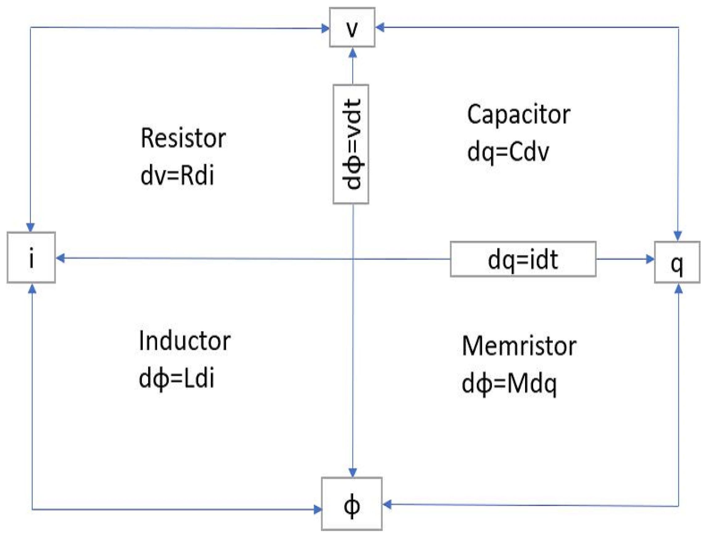
2. Modeling the Memristors

The number of transistors used in memristor circuits plays an important role in determining their performance and functionality. The number of transistors in a memristor circuit can affect its performance in several ways. The number of transistors determines the complexity of the circuit, which in turn affects its functionality and performance. Complex circuits, with more transistors, can perform more advanced computations and operate at higher speeds than simpler circuits. This number can impact the power consumption and heat dissipation of the circuit. As the number of transistors increases, so does the power consumption of the circuit, which can lead to increased heat generation. Careful design of the circuit is necessary, to ensure that it can operate within a safe temperature range. This number also can affect the cost of producing the circuit. More complex circuits with more transistors require more materials and manufacturing steps, which can drive up the cost of production. Therefore, careful consideration of the number of transistors used in a memristor circuit is necessary to balance performance, power consumption, and cost.

Working Principle of Memristors

The relations between four fundamental elements: current, voltage, charge, and flux, are shown in Figure 1. The relationship between charge and magnetic flux is known as memristor (M). In the memristor circuit, the current and voltage relationship can be defined as:
V ( t ) = R ( i ) i ( t ) = d Φ d q i ( t )
Here q(t) and (t) indicate the charge and flux with respect to time. So, the resistance in the time domain is defined as:
R = d Φ d q
The relation with charge and flux is nonlinear, so the value of resistance changes with different operating points of q. The resistance value remains the same if any external voltage or current is applied. As a result, the signal is memorized as the resistance value, named memristance (M). However, the memristor can be controlled by applying external voltage or current, where
R = M = d Φ d q ( q , Φ )

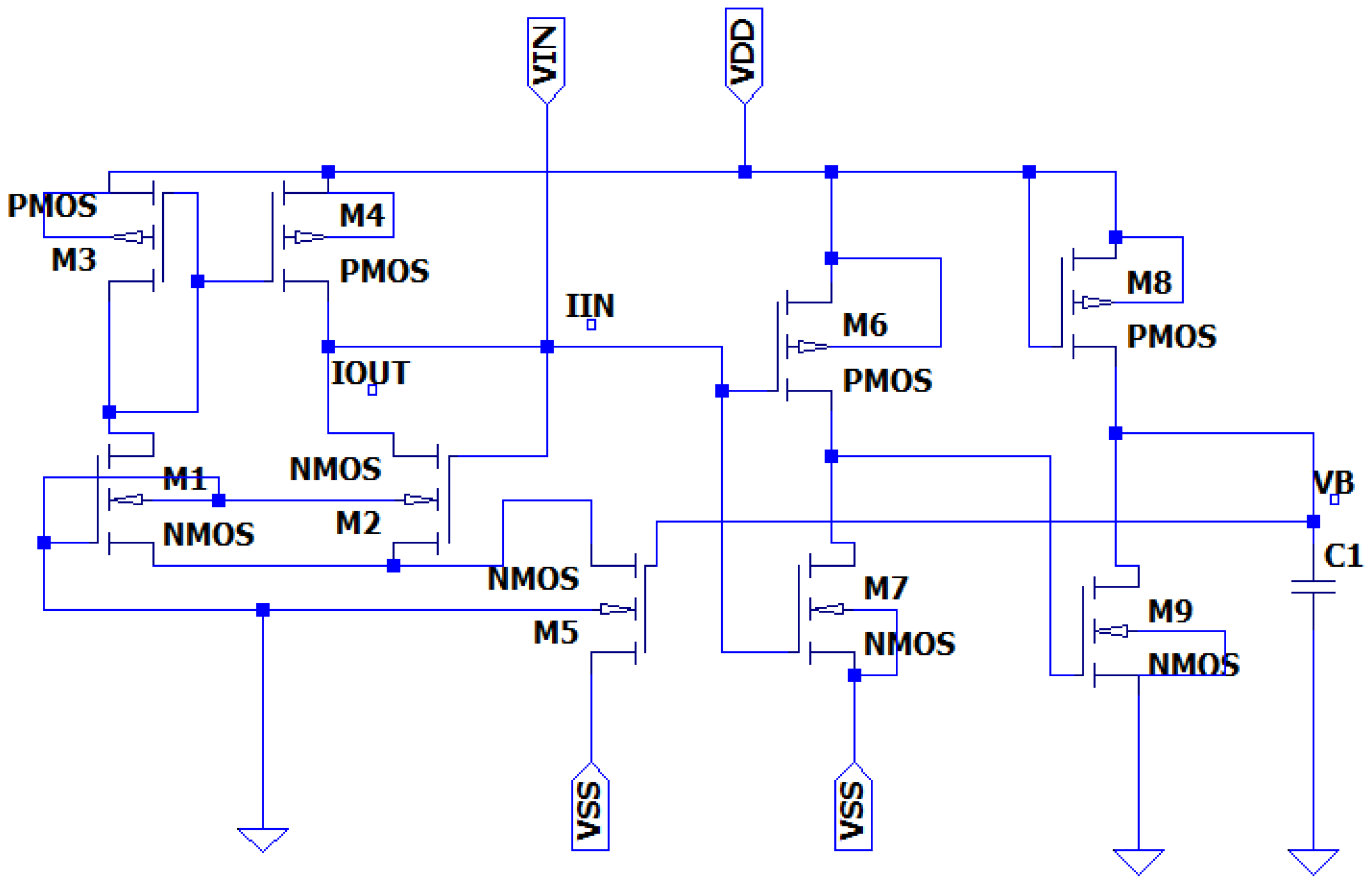
3. Proposed Memristor Circuit and Its Analysis

The proposed memristor is the only grounded emulator given in Figure 2. It consists of nine transistors and a grounded capacitor. The transistors M1 to M5 are the first stage of the transconductance stage, with differential input, and transistors M6 and M7 have a single input and a single output. Transistors M8 and M9 are used for configuring the partial positive feedback path, for additional transconductance gain. In this paper [37], by applying the KCL equation rule, the equation can be written as:
I I N = I O U T 1 = G m 1 V I N
Transconductance gain can be achieved from the M1–M5 transistors from the following equation:
G m 1 = μ n C o x 2 W L 1 , 2 W L 5 V B V S S V T H 5
where µn is the mobility of carriers, Cox is the gate the gate oxide capacitance per unit area, W is the width, and L is the length of the transistor. Accordingly, VTH-5 is the threshold voltage of the M5 transistors. The supply voltage of Vss is negative. From node 2 V B, voltage can be found as,
V B = 1 C G m 2 V I N d t
T h e r e f o r e , V B = G m 2 ϕ I N C
Here, the input flux is ΦIN and the transconductance gain of the second stage contains the M6–M9 transistors. The gain equation can be written as follows:
G m 2 = ( g 6 + g 7 + g 8 + g 9 )
Here, g6–g9 are the gains of transistors M6–M9, respectively. By substituting the Equations (2) and (4) into Equation (1), the memductance of the memristor emulator can be written as:
W ϕ N N = I N N V I N = K V s s V I H 5 g 6 + g 7 + g 8 + g 9 ϕ N V C K = μ m C a x 2 W L 1 , 2 W L 5 .
As a result, Equation (6) can be written as:
W ( ϕ N N ) = K ( V s s V I H 5 ) K ( ( g 6 + g 7 + g 8 + g 9 ) ϕ N V C )
From Equation (7), the MOSFET-based grounded incremental memristor emulator is obtained. Here, the first part is the linear time-invariant part, and the second part of the equation is the variable part. To investigate the frequency analysis, a sinusoidal voltage can be applied to the input terminals, and the generated flux can be written as:
ϕ I N = V m Cos ( ω t π ) ω
By rearranging Equations (7) and (8), the memductance equation can be written as:
W ϕ I N = K V s s V T H 5 K g 6 + g 7 + g 8 + g 9 Cos ( ω t π ) ω C
Equation (9) describes the proposed memristor emulator circuit, represented in Figure 1, as a resistor with different input voltage (Vin), frequency (f), capacitance (C), and source voltage Vss, and changing both capacitance and frequency.

Memristor Modeling Using CMOS

Memristor emulators are therefore being created to mimic their characteristics, using analog building blocks such as second-generation current conveyors (CCII) [24,25], operational transconductance amplifiers (OTA) [26], current feedback operational amplifiers (CFOA) [27], differential difference current conveyors (DDCC) [28], current conveyor transconductance amplifiers (CCTA) [29], current backward transconductance amplifiers (CBTA) [30], and so forth. However, the circuits are complex, and use an analog multiplier and several operational amplifiers, resistors, and MOS transistors. In many of those research papers, the area of the proposed design is also important and kept compact. Delay in memristors refers to the time it takes for the memristor to change its resistance in response to a change in input voltage. This delay is caused by the physical properties of the memristor material and the complex mechanisms that control its behavior. Improving the power consumption and the delay are also vital factors for the design [10,11,12,13,14]. Low-voltage Vdd-based memristors are a type of memristor that operates at a low supply voltage, typically below 1 V. This type of memristor is advantageous in low-power applications, where minimizing power consumption is critical. In addition, low-voltage Vdd-based memristors have the potential to operate at higher speeds and densities than traditional memristors, making them attractive for high-performance computing applications [38]. Design of binary memristors for energy-efficient image recognition using discrete cosine transform, was described in [39]. The proposal of a self-adjusting writes circuit, reduces power loss by optimizing writing pulse width, leading to reduced power consumption, with up to 76% savings, in simulations, compared to a fixed pulse width circuit [40].
Many software tools are being used for designing memristor circuits such as LTSpice, PSpice, NGspice, Cadence Virtuoso, and MATLAB/Simulink. Among them, LTSpice is a very popular open-source tool for linear and nonlinear circuit simulations. This tool is a free circuit simulation software developed by Linear Technology. With LTSpice, users can design and simulate memristor circuits using a graphical interface. The software allows users to choose from a variety of memristor models and parameters and then simulate the behavior of the circuit under different conditions. In many designs, authors used this tool for the design [14,41,42]. For user-friendliness, available resources, and simulation accuracy, LTSpice is used to simulate our design.

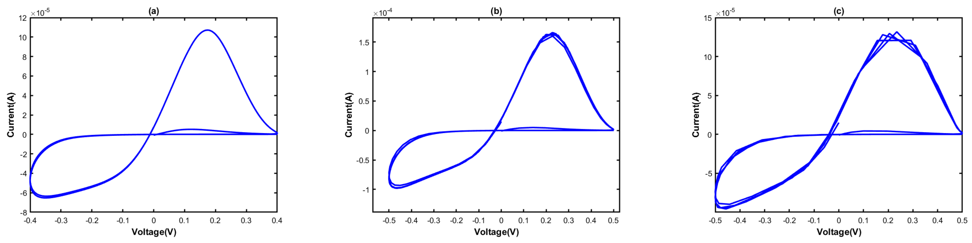
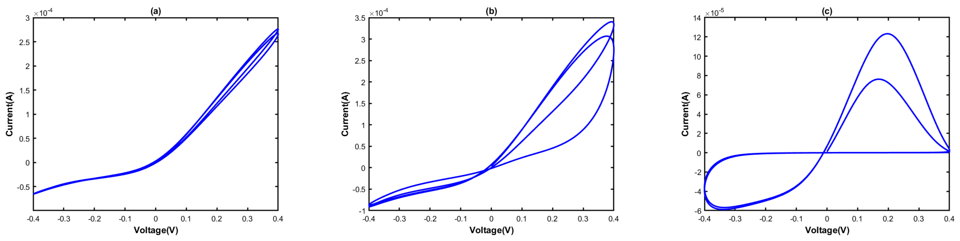
4. Simulation Results and Discussion

The present paper endeavors to present a comparative analysis of the design and performance parameters of a memristor circuit, proposed for use in the 45 nm and 16 nm CMOS technology parameters, within the LTSpice XVII environment. This study aims to explore the suitability of smaller process nodes, by presenting simulation-based results of the emulator’s performance, which may contribute to reduced manufacturing costs and better compatibility with low-powered devices. Nevertheless, it is imperative to acknowledge that the selection of the process technology node is ultimately contingent upon the specific requirements of the chip being designed, and the trade-offs among factors such as performance, power consumption, and cost. In this regard, to ascertain the reliability and robustness of the proposed circuit, it was subjected to simulations at different process corners and temperature changes.
Figure 2 exhibits the proposed memristor circuit, which employs a DC voltage supply of +0.9 V and −0.9 V, while the capacitance value is fixed at 100 nF. The aspect ratios of the circuit’s constituent components vary with the technology parameters.
In order to investigate the behavior of the designed memristor circuit, a sinusoidal voltage, with a peak value of 400 mV at a frequency of 2 kHz, was applied to its input terminal. The anticipated output of a memristor emulator circuit, including the pinched hysteresis loop and the in-phase relationship between voltage and current for 16 nm and 45 nm technology parameters (in contrast to capacitors and inductors), is depicted in Figure 3.
To further validate the performance of the proposed circuit, the transient response was examined for both 16 nm and 45 nm CMOS technology parameters, and the results are shown in Figure 4. Notably, no phase difference between voltage and current was observed, providing compelling evidence for the efficacy of the proposed design. These findings highlight the ability of the proposed memristor emulator to mimic the behavior of a true memristor circuit, and demonstrate its potential for use in various applications in electronics and computing.
The analysis of the frequency response of the memristor is a prominent characteristic in understanding its behavior. To validate the frequency-dependent characteristics and linear behavior of the model, a sinusoidal signal, with frequencies varying from low to high, was applied to the circuit, and the resulting voltage–current curves were plotted at 2 kHz, 10 kHz, and 20 kHz, with a fixed capacitor value of 100 nF, as shown in Figure 5 and Figure 6. It was observed that the memristor behaves like a resistor at high input frequencies, but the hysteresis loop became more distorted as the frequency increased. However, at 2 kHz, the circuit exhibited a better hysteresis loop, making it the optimal frequency for the final design. The memristor’s memory effect is achieved using a capacitor, and provides frequency dependence characteristics.
The voltage–current curves in Figure 7 and Figure 8 are presented as a function of varying capacitance values, which are commercially available. The curves exhibit an increasingly linear behavior with increasing capacitance values, particularly evident in the curves generated using capacitance values of 33 nF, 51 nF, and 100 nF. The memristor operation circuit’s tuning is also evident from the figures, indicating the circuit’s versatility and its ability to be tailored for specific requirements.
In Figure 9 and Figure 10, the performance of the proposed emulator is shown to vary with the product of frequency and capacitance values. Specifically, the operating frequencies and capacitors were chosen as f = 2 kHz, C = 100 nF; f = 4 kHz, C = 50 nF; and f = 10 kHz, C = 20 nF. Remarkably, the memristor exhibited almost identical voltage–current characteristics curves when the product of operating frequency was maintained constant. Moreover, the results were stable even when the product was varied, implying the circuit’s robustness and ability to withstand variations in operating conditions.
By varying the capacitance values, the voltage–current curves shown in Figure 6 were obtained. The curve becomes more linear as the capacitance value gets higher and the tuning of the memristor operation circuit also becomes evident. Figure 7 represents the performance of the proposed emulator varying with frequency and capacitance. Here, the operating frequency and capacitors were taken as f = 1 kHz, C = 12 pF; and f = 3 kHz, C = 4 pF, respectively. The memristor experienced almost the same voltage–current characteristics curve when the product of operating frequency was kept the same, and along with varying product, the results were stable.
Figure 11 and Figure 12 are shown to effectively demonstrate the influence of varying input voltage on the hysteresis loop. It was found that as the input voltage increased, such as from 300 mV to 400 mV, the curve became increasingly distorted. Conversely, at a low input voltage of 200 mV, the memristor emulator operated in a manner similar to a linear resistor. It is worth noting that the input voltage does indeed have a tangible impact on the hysteresis loop. As such, for the purposes of this experiment, a low input voltage of 200 mV was maintained. While this input voltage did result in a slightly distorted curve, it was determined that this value represented an ideal trade-off between the various outcomes under consideration. Indeed, the 200 mV peak input voltage yielded the most favorable outcome in every aspect, making it the optimal choice for this experiment.
The proposed design’s hysteresis loop exhibited notable variations when subjected to different Vss voltage values, as observed in Figure 13 and Figure 14. Specifically, the circuit displayed considerable variation in the loop when the Vss voltage value was low. To ascertain the impact of varying Vss voltage values on the hysteresis loop, three distinct voltage values were evaluated. Ultimately, it was discovered that the loop generated the lowest level of distortion when the Vss voltage was set to −0.9 V. This finding highlights the significance of Vss voltage in achieving optimal circuit performance and underscores the importance of careful consideration of this variable in the design and implementation of similar circuits.
Figure 15 and Figure 16 illustrate the results of various process corner simulations conducted on the proposed memristor emulator. These simulations were performed under different temperature conditions (−40 °C, 27 °C, and 80 °C) for the fast-NMOS/fast-PMOS (FF), slow-NMOS/slow-PMOS (SS), and nominal process conditions (TT). Despite being subjected to harsh environmental conditions, the memristor was observed to operate effectively, with only slight variations in the voltage curve. However, the voltage–current curve became distorted under different extreme temperatures. It is important to note that the current flow for the FF process corner was higher than that for the SS process corner.
In order to assess the statistical analysis and stability performance of the proposed memristor circuit, a Monte Carlo simulation was conducted. This technique is used to analyze the behavior of a circuit when the parameter values are varied between tolerance limits. Figure 17 shows the results of the Monte Carlo simulation for both 16 nm and 45 nm technologies. During the simulation, process corners and mismatches between the transistors were taken into account.
The presented memristor circuit demonstrates a slight change in the hysteresis loop characteristics if the components of the circuit have different values within the tolerance limit. However, it is important to note that the memristor is operating within the acceptable limit, indicating that the circuit is stable under different process conditions. The Monte Carlo simulation provides a comprehensive statistical analysis of the circuit’s behavior and can help identify potential issues with component tolerances and variations. Overall, the results demonstrate the robustness and reliability of the proposed memristor circuit.
Table 1 contrasts the proposed memristor emulator with previously published ones, in terms of component count, frequency, power supply, elements, and technology. Although this design realizes the circuit operation with a lower frequency and with 9 transistors, this grounded capacitor design, using 45 nm and 16 nm CMOS process technology and a lower supply voltage compared to other works presented here, produces excellent results, without any active component present in the circuit.
In order to provide a comprehensive assessment of the proposed memristor emulator, it is compared to previously published designs in Table 1. The table contrasts several parameters including component count, frequency, power supply, elements, and technology, enabling a thorough evaluation of the relative merits of the different designs. Despite the fact that the present design operates at a lower frequency and utilizes a mere nine transistors, the utilization of the grounded capacitor design, in conjunction with 16 nm and 45 nm process technology, and a lower supply voltage than other designs, engenders an exceptional outcome, without any active component in the circuit.

5. Conclusions

The current research endeavors to present a novel memristor emulator circuit that utilizes merely nine MOS transistors and a solitary grounded capacitor. A visual analysis comparing the 45 nm and 16 nm process technology, has also been included, to substantiate the trend of selecting process technology nodes in accordance with the particular specifications of the chip being designed, while weighing the competing factors of performance, power consumption, and manufacturing costs. In comparison to the extant literature on memristor circuits, the present study offers several benefits: firstly, a smaller number of components are employed, which translates into lower power consumption. Given the industry’s shift towards low-power technologies, this design presents a more viable option than existing designs. Secondly, the structure itself is simpler, which makes it more accessible for VLSI implementation. Thirdly, the design employs a grounded capacitor, and fourthly, it does not include active blocks as multipliers. The design operates at only +0.9 V and −0.9 V and exhibits a wider operating range. Ultimately, the performance parameters were rigorously tested, revealing a notable development in the pinched hysteresis loop, and the results were well-aligned with prior investigations.

Author Contributions

Conceptualization, P.K.G., S.Z.R. and M.S.A.; methodology, P.K.G., S.Z.R. and M.S.A.; software, P.K.G. and S.Z.R.; validation, P.K.G., S.Z.R. and M.S.A.; formal analysis, P.K.G. and S.Z.R.; investigation, P.K.G. and S.Z.R.; data curation, P.K.G., S.Z.R., M.S.A. and P.S.; writing—original draft preparation, P.K.G., S.Z.R., M.S.A. and P.S.; writing—review and editing, P.S.; visualization, P.K.G., S.Z.R., M.S.A. and P.S.; supervision, P.S.; project administration, P.S.; funding acquisition, P.S. All authors have read and agreed to the published version of the manuscript.

Funding

This research received no external funding.

Data Availability Statement

Not applicable to this project.

Conflicts of Interest

The authors declare no conflict of interest.

References

  1. Cao, Y.; Zheng, W.; Zhao, X.; Chang, C.H. An Energy-Efficient Current-Starved Inverter Based Strong Physical Unclonable Function with Enhanced Temperature Stability. IEEE Access 2019, 7, 105287–105297. [Google Scholar] [CrossRef]
  2. Ananda, Y.R.; Raj, N.; Trivedi, G. A MOS-DTMOS Implementation of Floating Memristor Emulator for High-Frequency Applications. IEEE Trans. Very Large Scale Integr. Syst. 2023, 31, 355–368. [Google Scholar]
  3. Mokhtar, S.M.A.B.; Abdullah, W.F.H. Memristor-CMOS interfacing circuit SPICE model. In Proceedings of the 2015 IEEE Symposium on Computer Applications & Industrial Electronics (ISCAIE), Langkawi, Malaysia, 12–14 April 2015; pp. 147–150. [Google Scholar]
  4. Mokhtar, S.M.A.; Abdullah, W.F.H.; Kadiran, K.A.; Rifin, R.; Omar, M. Write and read circuit for memristor analog resistance switching. In Proceedings of the 2017 IEEE 8th Control and System Graduate Research Colloquium (ICSGRC), Shah Alam, Malaysia, 4–5 August 2017; pp. 13–16. [Google Scholar]
  5. Raja, T.; Mourad, S. Digital logic implementation in memristor-based crossbars. In Proceedings of the 2009 International Conference on Communications, Circuits and Systems, Milpitas, CA, USA, 23–25 July 2009; IEEE: Piscataway, NJ, USA, 2009; pp. 939–943. [Google Scholar]
  6. Kvatinsky, S.; Satat, G.; Wald, N.; Friedman, E.G.; Kolodny, A.; Weiser, U.C. Memristor-based material implication (IMPLY) logic: Design principles and methodologies. IEEE Trans. Very Large Scale Integr. Syst. 2013, 22, 2054–2066. [Google Scholar] [CrossRef]
  7. Yadav, P.; Das, B. Memristor-based Memory Cell with Less Noise Margins and Storing Non-Binary Data. In Physics of Semiconductor Devices: 17th International Workshop on the Physics of Semiconductor Devices 2013; Springer: Berlin/Heidelberg, Germany, 2014; pp. 183–187. [Google Scholar]
  8. Smagulova, K.; Tankimanova, A.; James, A.P. CMOS-Memristor Hybrid Integrated Pixel Sensors. In Proceedings of the 2016 IEEE International Symposium on Nanoelectronic and Information Systems (iNIS), Gwalior, India, 19–21 December 2016; pp. 34–37. [Google Scholar]
  9. Mokhtar, S.M.A.B.; Abdullah, W.F.H. Re-model fabricated memristor behavior in LT-SPICE and applied in logic circuit. In Proceedings of the 2014 IEEE Symposium on Computer Applications and Industrial Electronics (ISCAIE), Penang, Malaysia, 7–8 April 2014; pp. 106–110. [Google Scholar]
  10. Alammari, K.; Ahmadi, A.; Ahmadi, M. Hybrid Memristor-CMOS Based Up-Down Counter Design. In Proceedings of the 2020 27th IEEE International Conference on Electronics, Circuits and Systems (ICECS), Glasgow, UK, 23–25 November 2020; pp. 1–4. [Google Scholar]
  11. Nissi, V.G.; Musala, S.; Veerayya, J. Memristor based full subtractor. In Proceedings of the 2022 International Conference on Communication, Computing and Internet of Things (IC3IoT), Chennai, India, 10–11 March 2022; pp. 1–5. [Google Scholar]
  12. Khurana, P.S.; Singh, K.; Sharma, A. A Hybrid CMOS-Memristor based Programmable Wien Bridge Oscillator. In Proceedings of the 2018 3rd IEEE International Conference on Recent Trends in Electronics, Information & Communication Technology (RTEICT), Bangalore, India, 18–19 May 2018; pp. 2207–2210. [Google Scholar]
  13. Verma, A.; Akashe, S. Low-power application for nano scaled Memristor based 2:1 multiplexer. In Proceedings of the 2015 International Conference on Communication Networks (ICCN), Gwalior, India, 19–21 November 2015; pp. 33–36. [Google Scholar]
  14. Peddi, A.; Y, P.S.; Hassan, S.; Polam, S.R.; R, S.K.; K, K.S. Design of Memristor Based Logic Gates for Low-Power Wireless Sensors in Biomedical Applications. In Proceedings of the 2021 6th International Conference on Signal Processing, Computing and Control (ISPCC), Solan, India, 7–9 October 2021; pp. 364–367. [Google Scholar]
  15. Krestinskaya, O.; James, A.P.; Chua, L.O. Neuromemristive circuits for edge computing: A review. IEEE Trans. Neural Netw. Learn. Syst. 2019, 31, 4–23. [Google Scholar] [CrossRef] [Green Version]
  16. Hadis, N.S.M.; Abd Manaf, A.; Herman, S.H.; Ngalim, S.H. ROFF/RON ratio of nano-well fluidic memristor sensor towards hydroxide based liquid detection. In Proceedings of the 2015 IEEE 15th International Conference on Nanotechnology (IEEE-Nano), Rome, Italy, 27–30 July 2015; IEEE: Piscataway, NJ, USA, 2015; pp. 1078–1081. [Google Scholar]
  17. Carrara, S.; Sacchetto, D.; Doucey, M.A.; Baj-Rossi, C.; De Micheli, G.; Leblebici, Y. Memristive-biosensors: A new detection method by using nanofabricated memristors. Sens. Actuators B Chem. 2012, 171, 449–457. [Google Scholar] [CrossRef] [Green Version]
  18. Sacchetto, D.; Doucey, M.A.; De Micheli, G.; Leblebici, Y.; Carrara, S. New insight on bio-sensing by nano-fabricated memristors. BioNanoScience 2011, 1, 1–3. [Google Scholar] [CrossRef]
  19. Krestinskaya, O.; James, A.P. Analogue neuro-memristive convolutional dropout nets. Proc. R. Soc. A 2020, 476, 20200210. [Google Scholar] [CrossRef]
  20. Kabir, M.; Mummadi, T.; Sundaravadivel, P. Poster: Towards Edge-Intelligent Drowning Detection System. In Proceedings of the 16th International Conference on Underwater Networks and Systems, Boston, MA, USA, 14–16 November 2022. [Google Scholar]
  21. Sundaravadivel, P.; Fitzgerald, A.; Indic, P. i-SAD: An Edge-Intelligent IoT-Based Wearable for Substance Abuse Detection. In Proceedings of the IEEE International Symposium on Smart Electronic Systems (iSES), Rourkela, India, 16–18 December 2019. [Google Scholar]
  22. Sundaravadivel, P.; Salvatore, P.; Indic, P. M-SID: An IoT-based Edge-intelligent Framework for Suicidal Ideation Detection. In Proceedings of the IEEE 6th World Forum on Internet of Things (WF-IoT), New Orleans, LA, USA, 2–16 June 2020; pp. 1–6. [Google Scholar]
  23. Fu, T.; Liu, X.; Gao, H.; Ward, J.E.; Liu, X.; Yin, B.; Wang, Z.; Zhuo, Y.; Walker, D.J.; Joshua Yang, J.; et al. Bioinspired bio-voltage memristors. Nat. Commun. 2020, 11, 1861. [Google Scholar] [CrossRef] [Green Version]
  24. Elwakil, A.S.; Fouda, M.E.; Radwan, A.G. A simple model of double-loop hysteresis behavior in memristive elements. IEEE Trans. Circuits Syst. II Express Briefs 2013, 60, 487–491. [Google Scholar] [CrossRef]
  25. Kumngern, M. A floating memristor emulator circuit using operational transconductance amplifiers. In Proceedings of the 2015 IEEE International Conference on Electron Devices and Solid-State Circuits (EDSSC), Singapore, 1–4 June 2015; IEEE: Piscataway, NJ, USA, 2015; pp. 679–682. [Google Scholar]
  26. Sözen, H.; Çam, U. Electronically tunable memristor emulator circuit. Analog. Integr. Circuits Signal Process. 2016, 89, 655–663. [Google Scholar] [CrossRef]
  27. Sánchez-López, C.; Mendoza-Lopez, J.; Carrasco-Aguilar, M.; Muñiz-Montero, C. A floating analog memristor emulator circuit. IEEE Trans. Circuits Syst. II Express Briefs 2014, 61, 309–313. [Google Scholar]
  28. Yeşil, A.; Babacan, Y.; Kaçar, F. A new DDCC based memristor emulator circuit and its applications. Microelectron. J. 2014, 45, 282–287. [Google Scholar] [CrossRef]
  29. Ranjan, R.K.; Rani, N.; Pal, R.; Paul, S.K.; Kanyal, G. Single CCTA based high frequency floating and grounded type of incremental/decremental memristor emulator and its application. Microelectron. J. 2017, 60, 119–128. [Google Scholar] [CrossRef]
  30. Ayten, U.E.; Minaei, S.; Sağbaş, M. Memristor emulator circuits using single CBTA. AEU-Int. J. Electron. Commun. 2017, 82, 109–118. [Google Scholar] [CrossRef]
  31. Chua, L. Memristor-the missing circuit element. IEEE Trans. Circuit Theory 1971, 18, 507–519. [Google Scholar] [CrossRef]
  32. Strukov, D.B.; Snider, G.S.; Stewart, D.R.; Williams, R.S. The missing memristor found. Nature 2008, 453, 80–83. [Google Scholar] [CrossRef]
  33. Williams, R.S. How we found the missing memristor. IEEE Spectr. 2008, 45, 28–35. [Google Scholar] [CrossRef]
  34. Shadaram, A.; Mirzakuchaki, S.; Zakerian, F. A one-memristor cell implementation of a non-volatile memory system. Can. J. Electr. Electron. Eng. 2011, 2, 346–352. [Google Scholar]
  35. Ho, Y.; Huang, G.M.; Li, P. Nonvolatile memristor memory: Device characteristics and design implications. In Proceedings of the 2009 International Conference on Computer-Aided Design, San Jose, CA, USA, 2–5 November 2009; pp. 485–490. [Google Scholar]
  36. Kim, H.; Sah, M.P.; Yang, C.; Roska, T.; Chua, L.O. Neural synaptic weighting with a pulse-based memristor circuit. IEEE Trans. Circuits Syst. I Regul. Pap. 2011, 59, 148–158. [Google Scholar] [CrossRef]
  37. Yesil, A. A new grounded memristor emulator based on MOSFET-C. AEU-Int. J. Electron. Commun. 2018, 91, 143–149. [Google Scholar] [CrossRef]
  38. Ham, S.J.; Mo, H.S.; Min, K.S. Low-Power VDD/3 Write Scheme with Inversion Coding Circuit for Complementary Memristor Array. IEEE Trans. Nanotechnol. 2013, 12, 851–857. [Google Scholar] [CrossRef]
  39. Truong, S.N.; Shin, S.; Byeon, S.D.; Song, J.; Min, K.S. New Twin Crossbar Architecture of Binary Memristors for Low-Power Image Recognition with Discrete Cosine Transform. IEEE Trans. Nanotechnol. 2015, 14, 1104–1111. [Google Scholar] [CrossRef]
  40. Jo, K.H.; Jung, C.M.; Min, K.S.; Kang, S.M. Self-Adaptive Write Circuit for Low-Power and Variation-Tolerant Memristors. IEEE Trans. Nanotechnol. 2010, 9, 675–678. [Google Scholar]
  41. Solovyeva, E.B.; Azarov, V.A. Comparative Analysis of Memristor Models with a Window Function Described in LTspice. In Proceedings of the 2021 IEEE Conference of Russian Young Researchers in Electrical and Electronic Engineering (ElConRus), St. Petersburg, Russia, 26–28 January 2021; pp. 1097–1101. [Google Scholar]
  42. Mokhtar, S.M.A.B.; Abdullah, W.F.H.W. Memristor based delay element using current starved inverter. In Proceedings of the RSM 2013 IEEE Regional Symposium on Micro and Nanoelectronics, Daerah Langkawi, Malaysia, 25–27 September 2013; pp. 81–84. [Google Scholar]
  43. Ranjan, R.K.; Raj, N.; Bhuwal, N.; Khateb, F. Single DVCCTA based high frequency incremental/decremental memristor emulator and its application. AEU-Int. J. Electron. Commun. 2017, 82, 177–190. [Google Scholar] [CrossRef]
  44. Yadav, N.; Rai, S.K.; Pandey, R. New grounded and floating memristor emulators using OTA and CDBA. Int. J. Circuit Theory Appl. 2020, 48, 1154–1179. [Google Scholar] [CrossRef]
  45. Vista, J.; Ranjan, A. A Simple Floating MOS-Memristor for High-Frequency Applications. IEEE Trans. Very Large Scale Integr. Syst. 2019, 27, 1186–1195. [Google Scholar] [CrossRef]
  46. Ghosh, M.; Singh, A.; Borah, S.S.; Vista, J.; Ranjan, A.; Kumar, S. MOSFET-Based Memristor for High-Frequency Signal Processing. IEEE Trans. Electron Devices 2022, 69, 2248–2255. [Google Scholar] [CrossRef]
Figure 1. The memristor comprises four fundamental passive electrical components.
Electronics 12 01654 g001
Figure 2. Proposed memristor emulator circuit.
Electronics 12 01654 g002
Figure 3. The pinched hysteresis loop of the final design: (a) 16 nm and (b) 45 nm.
Electronics 12 01654 g003
Figure 4. Transient response of the proposed memristor emulator: (a) 16 nm and (b) 45 nm.
Electronics 12 01654 g004
Figure 5. Voltage–current curves for 16 nm, when frequency is (a) 2 kHz, (b) 10 kHz, and (c) 20 kHz.
Electronics 12 01654 g005
Figure 6. Voltage–current curves for 45 nm, when frequency is (a) 2 kHz, (b) 10 kHz, and (c) 20 kHz.
Electronics 12 01654 g006
Figure 7. Voltage–current curves of varying capacitance, for 16 nm: (a) 33 nF, (b) 51 nF, and (c) 100 nF.
Electronics 12 01654 g007
Figure 8. Voltage–current curves of varying capacitance, for 45 nm: (a) 33 nF, (b) 51 nF, and (c) 100 nF.
Electronics 12 01654 g008
Figure 9. Voltage–current curves of various operating frequencies and capacitance, for 16 nm: (a) f = 2 kHz, C = 100 nF; (b) f = 4 kHz, C = 50 nF; and (c) f = 10 kHz, C = 20 nF.
Electronics 12 01654 g009
Figure 10. Voltage–current curves of various operating frequencies and capacitance, for 45 nm: (a) f = 2 kHz, C = 100 nf; (b) f = 4 kHz, C = 50 nf; and (c) f = 10 kHz, C = 20 nf.
Electronics 12 01654 g010
Figure 11. Hysteresis loops for different amplitudes of input voltages, for 16 nm: (a) 200 mV, (b) 300 mV, and (c) 400 mV.
Electronics 12 01654 g011
Figure 12. Hysteresis loops for different amplitudes of input voltages for 45 nm: (a) 200 mV, (b) 300 mV, and (c) 400 mV.
Electronics 12 01654 g012
Figure 13. Hysteresis loops for different amplitudes of source voltages, for 16 nm: (a) −0.6 V, (b) −0.7 V, and (c) −0.8 V.
Electronics 12 01654 g013
Figure 14. Hysteresis loops for different source voltages, for 45 nm: (a) −0.6 V, (b) −0.7 V, and (c) −0.8 V.
Electronics 12 01654 g014
Figure 15. Pinched hysteresis loops for temperatures and process corners, for 16 nm: (a) −40 °C, (b) 27 °C, and (c) 80 °C.
Electronics 12 01654 g015
Figure 16. Pinched hysteresis loops for temperatures and process corners, for 45 nm: (a) −40 °C, (b) 27 °CC, and (c) 80 °C.
Electronics 12 01654 g016
Figure 17. Monte Carlo simulation of the proposed memristor: (a) 16 nm and (b) 45 nm.
Electronics 12 01654 g017
Table 1. Comparison of the proposed memristor with other presented memristor emulators.
ComponentsFrequencyPower SupplyElementsTechnologyRef.
DVC-11 MHz2 Vgrounded0.5 um CMOS[43]
1 OTA, CDBA1 MHz±0.9 VfloatingCMOS 0.18 um[44]
MOSFETs13 MHz1 Vfloating0.18 um CMOS technology[45]
1 CBTA and multiplier460 kHz±0.9 VgroundedTSMC 0.18 um[30]
7 transistors50 MHz±10 VgroundedCMOS discrete off the shelf elements[37]
nMmos-3, MOS-CAP-15 MHz1.3 Vfloating90 nm GPDK CMOS[46]
DDCC-11 MHzNAgrounded0.35 um CMOS technology[27]
This work2 kHz±0.9 Vgrounded45 nm and 16 nm CMOS technology
Disclaimer/Publisher’s Note: The statements, opinions and data contained in all publications are solely those of the individual author(s) and contributor(s) and not of MDPI and/or the editor(s). MDPI and/or the editor(s) disclaim responsibility for any injury to people or property resulting from any ideas, methods, instructions or products referred to in the content.

