Communication

Substrate Integrated Waveguide Based Cavity-Backed Circularly-Polarized Antenna for Satellite Communication

1
Intelligent Wireless Network Department, Zhejiang Laboratory, Hangzhou 311121, China
2
College of Electronic and Information Engineering, Hangzhou Dianzi University, Hangzhou 311121, China
*
Author to whom correspondence should be addressed.
Electronics 2023, 12(7), 1669; https://doi.org/10.3390/electronics12071669
Submission received: 28 February 2023 / Revised: 27 March 2023 / Accepted: 30 March 2023 / Published: 31 March 2023
(This article belongs to the Special Issue Recent Advances in Microwave and Terahertz Engineering)

Abstract

:
This article presents the methodology to design a single-fed circularly-polarized antenna with low front-to-back ratio (FBR). A circular-patch (CPatch) antenna has been incorporated within the rectangular-cavity, made of, substrate integrated waveguide (SIW). The size of the CPatch and the SIW cavity has been chosen appropriately, in a manner, that the both resonators dominant mode coincide. This arrangement has been adopted to realize the basic radiating unit with no surface-wave and the significantly lower FBR. The circularly polarization has been excited through shorting the periphery of CPatch radiator to the “one of the two metallic grounds” of this SIW cavity. The patch periphery has been shorted from two distinct points, separated by the quarter wavelength—over center frequency of working band. The antenna has been designed and manufactured over Rogers RT/Duroid 5880 substrate with dielectric constant (εr) of 2.2, loss-tangent (tan δ, at 10 GHz) of 0.0009, and substrate height of 0.508 mm. Southwest® end launcher (SEL) along with SIW-to-GCPW (Grounded Co-Planar Waveguide) transition has been used here to facilitate the measurement of antenna’s electrical and the radiation performance. The designed antenna’s impedance bandwidth and the 3 dB axial-ratio (AR) bandwidth is 9.5% and the 2.3%, respectively. It’s simulated and the measured peak gain, within working frequency band, is higher than 8.5dBic. The proposed antenna’s FBR is antenna is significantly lower than the conventional circularly-polarized antennas. Through comparative study, with work in open literature, it has been demonstrated that the designed antenna, based on proposed method, can a potential candidate for applicable in satellite and in the other spaceborne communication system’s module—at ground and in the space station.

1. Introduction

Circularly polarized (CP) has been widely adopted and taken in use as the prominent mode of operation for satellites communication, global positioning system (GPS), and the spaceborne synthetic aperture radar (SAR)—due to its resilience in combating the multi-path fading and the ability to nullify the “Faraday rotation” effect, when Electromagnetic (EM) radiation passes through the ionosphere [1]. Although, the antenna theory is well developed and about a century old, the antenna technology is still evolving. Take example of the circularly polarized antenna, there are three potential methods to realize and engineer the CP antenna namely, (a) the single-feed method with geometric deformation in the antenna’s radiator structure [2], (b) through excitation of the degenerated modes within linearly-polarized radiator, via modified feeding network consists of a  90 °  broadband balun [3,4], and (c) by forming the basic 2 × 2 subarray of the linearly-polarized radiators with unique element angular and the phase-difference arrangements [5]. Each method have its advantages and the disadvantages; in (b) the broadband balun based antenna provides the wide axial-ratio (AR) bandwidth; nevertheless, the same balun could also degrade the total antenna performance through secondary effects. Especially in phased array antenna system and in the high-gain antenna array—fed through corporate-feed network. Over millimeter wave (MMWave) and the higher frequencies this 90° broadband balun might degrade the antenna’s polarization purity caused by coupling between feed lines of the two adjacent radiator and the surface-wave—that could be excited in the substrate of feeding network. The 2 × 2 array of the (c) do provides the excellent performance over wider bandwidth; however, the radiators based on this method could not be used in phased-array design due to their larger size. If applied, as per the antenna array theory the larger grating lobes could emerge in array’s radiation pattern—as the spacing between two basic radiators might be greater than one full wavelength [6] in free space. Therefore, over the MMWave frequencies the most suitable technique to design CP antennas—especially for the array design—would be the single-feed method. The new dimensions, in the antenna’s performance improvement, could be added through “surrounded the main-radiator via cavity” to shield the spurious radiations and the back scattering. Such antennas are called the cavity-backed (CB) antenna.
CB antennas are not new and has been studied widely [7,8], let’s take the example of the metallic waveguide-based CB CP antenna, over sub-6 GHz frequency band presented in [7], where the waveguide not merely improves the FBR but also guaranteed the higher polarization purity—over wider beamwidth. Nevertheless, metallic waveguides are bulky and hinders the antenna integration with other RF components, especially over MMWave frequencies, where the antennas use cases and the deployment scenarios are quite different. SIW, which is the realization of waveguides over printed circuit board (PCB) [9] already became the part of mainstream research and widely adopted in engineering work [10,11,12]. Variety of SIW cavity-backed planar CP antennas has been reported in the open literature [13,14,15,16,17,18]. The antenna reported in [14] is a dual-band CP antenna and in that each band’s radiation mechanism is different―here the multilayer substrate-structure has been utilized to realize the “well impedance-matched” dual-band CP antenna; however, the feeding method is still based on aperture-coupling. In [16] the SIW based 2 × 2 polarization reconfigurable antenna array has been reported over 8.4 GHz, where in CP mode the 3 dB AR bandwidth is 3.25%; nevertheless, the large feeding network of the antenna increases the metallic and dielectric losses. Also, the feeding network arrangement in [16] makes its CP radiating unit less attractive, for the phased-array applications.
In this article a single-feed CB CP antenna has been reported, working over the 34 GHz frequency band. To be noted the 34 GHz band is only an exemplary and the same concept can be applied in making the antenna over any desired frequency band as per project specification including the Ku band—which is popular for the satellite communication. The proposed antenna has been designed on a single substrate layer and fed through the another SIW section, forged within the same substrate material. Here the CPatch antenna, which is working as main radiator, has been incorporated within the rectangular cavity (RC). The RC is resonating at its dominant mode TE110 and the CPatch is resonating at its dominant mode TM110. The TM110 mode of the CPatch is a degenerated mode and exploited to excite the circular polarization in antenna structure. To excite the degenerated modes within the patch antenna, the patch has been fed through two district points, separated by quarter-wavelength. The conceptualization of the total antenna working principle has been elaborated in a way that the cavity resonance is only playing the role to inject the energy within radiating structure and do not participate in the total antenna’s radiation mechanism The CP wave is only generated due to the excitation of degenerated modes within CPatch—which is fed from two orthogonally oriented junctions. The electric current is coming from the SIW feed-line, when it enters within cavity it first reaches the first feeding point of the CPatch and then it further travels the path length equivalent to quarter-wavelength before reaching the second feeding section connected to CPatch’s periphery. Figure 1 illustrate the clear idea and summarize the words into topology. Here the 90° phase shifter of Figure 1 is equivalents to the quarter-wavelength long electric-path—over the cavity’s ground surface. Proposed antenna is simple in design and it can achieve the measured AR bandwidth of 2.3% over the working band’s center frequency 33.4 GHz, with the peak gain of 9.6 dBi at 33.7 GHz.

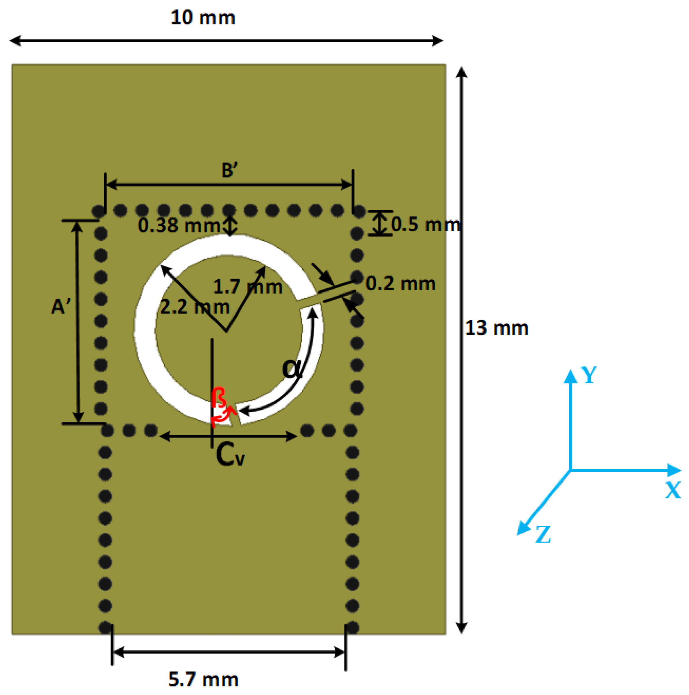
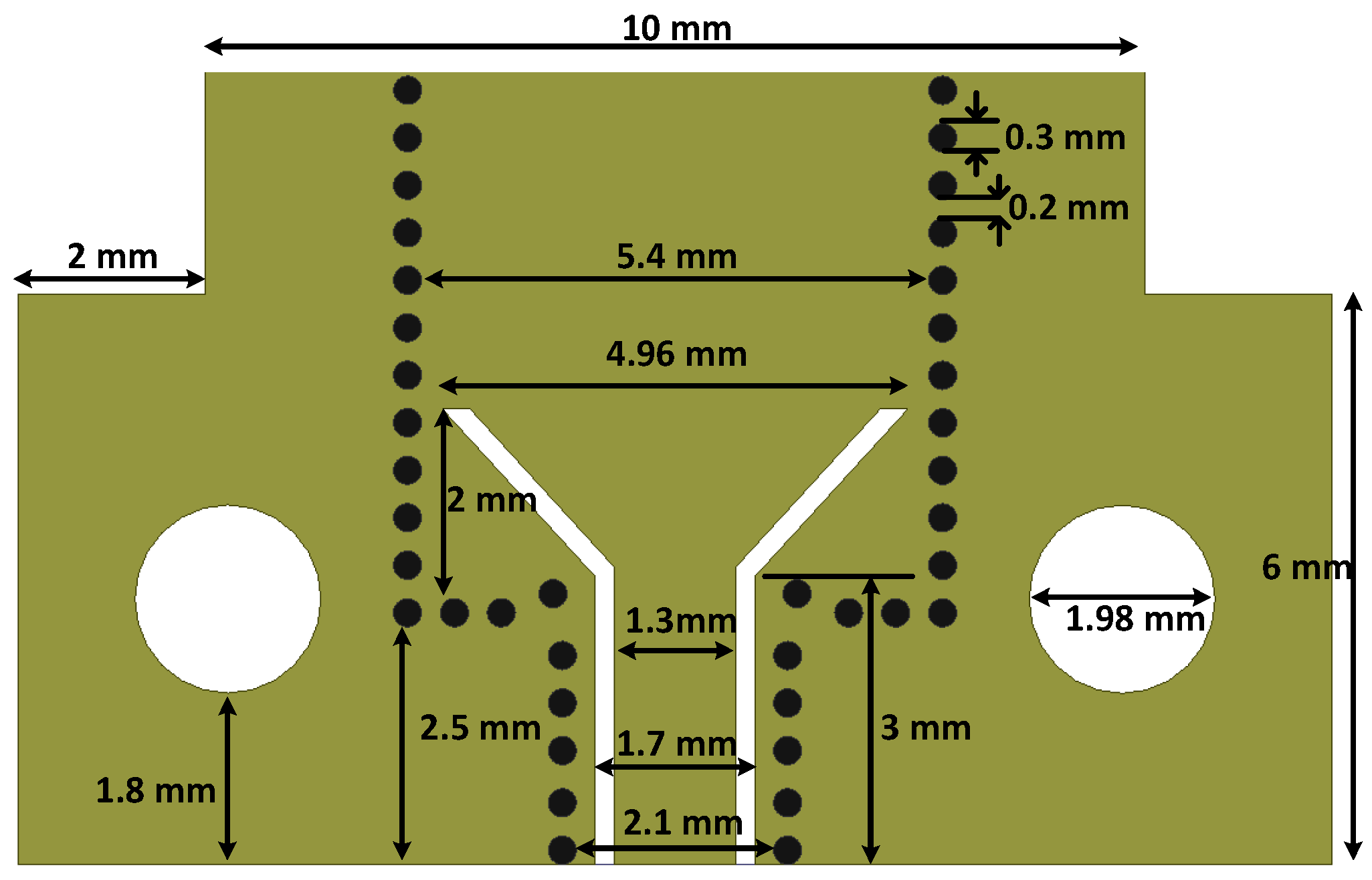
2. Antenna Structure and Design Principles

Figure 2 shows the geometry of the proposed antenna element with detailed dimensions, designed over Rogers RT/Duroid 5880, with substrate height of 0.508 mm. The key design parameters of the RC are  A , B ,  and the cavity opening width  C V . The fine tuning of  C V  guarantees the antenna’s impedance matching for better, return-loss performance, and the radiation efficiency. The initial value of the  A , B  can be calculated by [19]
f m n l = c 2 π μ r ε r m π A 2 + n π B 2 + l π C 2
where,  A ,   B ,   a n d   C  are the internal length, width, and height (substrate height) of the SIW-cavity, respectively.  f m n l  represent the cutoff frequency of RC cavity modes. In reference to the RC cavity of Figure 2 and the values of  A , B  in Table 1. the first three resonance modes cutoff frequency points should be the TE110 at 28.02 GHz, TE120 at 41.99 GHz, and TE210 at 46.5 GHz. The value of  C V  can be obtained through simulation and the optimization in Ansys HFSS-2021. As stated above the RC is merely for injecting the energy in radiator and to block the back scattering—the main radiator is the CPatch antenna, operating at its dominant mode TM110. The resonance frequency  f r 110  of the CPatch can be calculated by [20]
f r 110 = 1.8412 c 2 π a μ r ε r
here  c  is the speed of light,  a  is the radius of the Cpatch;  μ r  and  ε r  are the substrate relative permeability and permittivity, respectively. As per the dimensions given in Figure 2 the patch resonance frequency is 34.882 GHz.
It has been observed that as in [11] where the TCSRS-antenna is shorted to the SIW cavity ground, if we shorted the Cpatch within RC is shorted to the cavity’s upper metallic-layer (in same plane), the “total antenna structure” resonates on its CPatch’s dominant mode  T M 110 . Therefore, in Figure 2 we have shorted the CPatch from two different points, orthogonal to each other, separated by quarter-wavelength. This leads to the excitation of CP wave in the antenna structure. The parametric study suggests that by changing the “angular-separation (α) between the two shorting-strips” or “the angular-orientation (ß) of the first shorting strips in-reference to the main axis of the antenna passing through the center of the Cpatch”, the resonance points of the degenerated modes  T M 110 T M 110  change significantly. The good starting point for the value of  α  start with quarter-wavelength at 34.8 GHz in Rogers RT/Duroid 5880 material. The width of the slot within cavity, in surrounding of the patch antenna, and the width of metallic-strip (MStrip) connecting the patch periphery to the RC ground are 0.5 mm and 0.2 mm, respectively. These variables precise value obtained through the optimization of the total antenna performance—in terms of impedance matching and the 3dB AR bandwidth. Through simulation, it has been observed that the narrower the Mstrip the better the antenna’s AR performance; due to the manufacturing limitation its value has been limited to 0.2 mm. The dimensions of the SIW feed-line should be large enough that the TE10 mode can be excited at a frequency—slightly lower than the working frequency of antenna this feed-line is feeding. The position of the CPatch, in the X-axis also plays the key role in optimizing the total antenna performance obtained through simulation.
Figure 3 illustrate the surface current-density (SCD) on the antenna’s metallic surface at 34 GHz, obtained through simulation in Ansys HFSS-2021. It can be observed that the two Mstrips are injecting energy onto CPatch, simultaneously, and the change in injected-field’s phase from 0 °  to 90 °  do not change the SDC or the SCD-ratio, over these two junctions. The only change in the SCD—can be observed—due to the changes in excitation phase is that the current vector orientation is rotating. Which align with the idea that proposed antenna is radiating the CP waves.

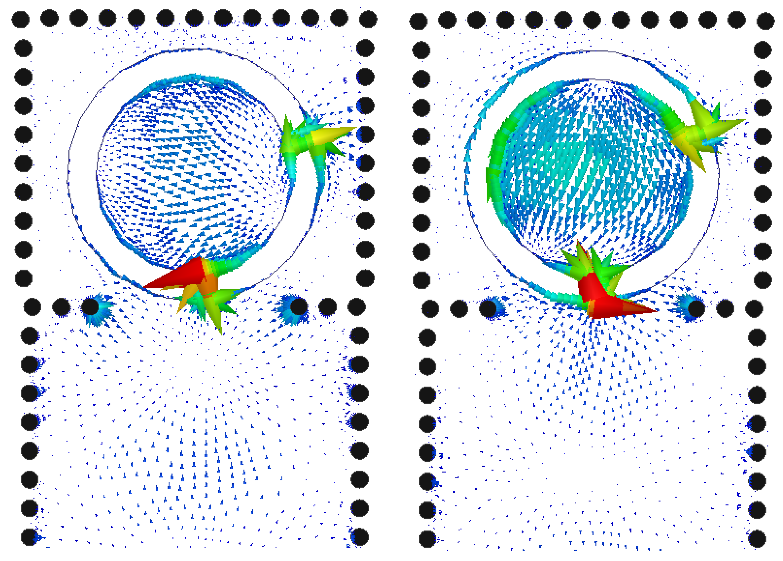
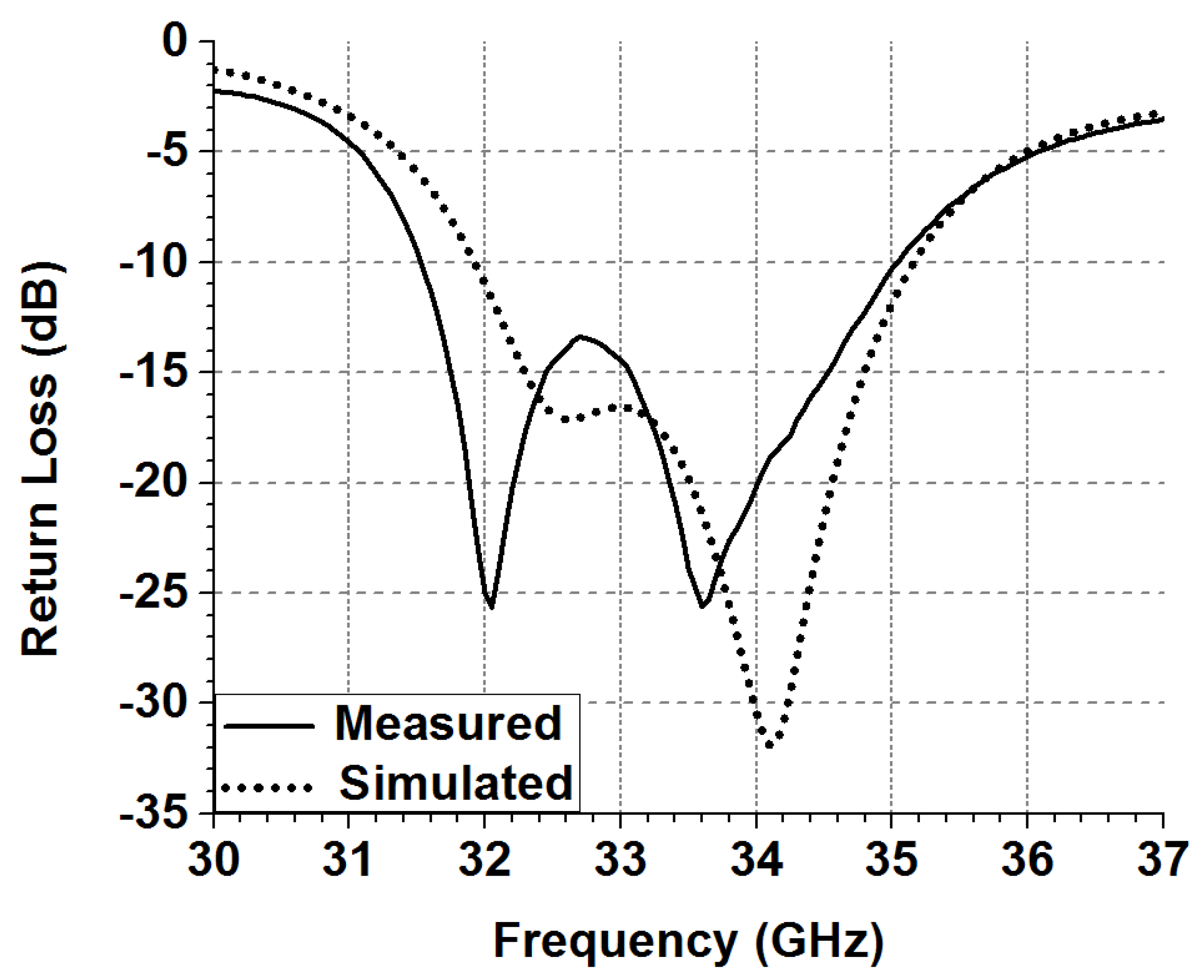
3. Results and Discussion

The prototype of the antenna with specification—in Figure 2, in Table 1, and with the description in second section of this article—has been manufactured using standard low-cost single-layer PCB process. The SIW-to-GCPW transition is used here, along with SEL, to facilitate the measurement of the proposed antenna. In the practical use case scenario, the SIW-to-GCPW is not compulsory and it has been used here, merely to facilitated the electrical connection between testing-equipment and the antenna under test (AUT). The SIW-to-GCPW transition is designed through simulation, inspired from the work reported in [11], and the detailed dimensions of the optimized structure are shown in Figure 4. Figure 5 present the photograph of fabricated antenna showing its front- and the back-side view—along with supporting components including SEL.
The simulated and the measured return-loss performance of the design antenna, presented in Figure 5, is shown in Figure 6. The test results match well with the simulation and the measured  S 11 10   d B  impedance bandwidth is around 9.5%. There is slight frequency shift of about 300–400 MHz, towards lower frequency, that should be due to the changes in substrate material properties, as the parameters given in the datasheet of the Rogers RT/Duroid 5880 are extracted over 10 GHz, only [21]. To measure the far-field radiation characteristics of the proposed CP antenna, the rotating linearly-polarized horn antenna has been used as the source. The method from [22] has been adopted to extract the antenna radiation parameters from test data including the AR, and the peak-gain. The absolute gain of the CP antenna can be extracted from radiation pattern, using [23]
G ( d B i c ) = G m a x + 3 + 20 log 1 + 10 r 20 2
Figure 7 illustrate the combined measured and simulated AR as well as combined measured and the simulated gain over frequency graph. The measured AR-bandwidth is about 2.3% and wider than in simulated results. In simulation the boresight-gain of the proposed antenna is quite stable and in a range of 8 to 8.5 dBic. Nevertheless, the measured gain over frequency graph is not stable; at such higher frequency when the radiator is relatively smaller, any foreign object in vicinity could have unwanted influence. It is highly likely that the SEL could have caused the gain fluctuation over frequency.
The normalized, measured (at 33.35 GHz) and the simulated (34 GHz), radiation pattern of CP antenna is shown in Figure 8. The reason to choose the different frequency points in measured and the in simulated radiation pattern graph, in Figure 8, is the frequency shift of around 500 MHz, towards lower frequency, observed from AR vs. frequency graph. The results shows the good agreement between simulated and the measured radiation performance, especially in the E-plane. Also, in the E-plane the 3 dB AR beamwidth is wider than 120°. In H-plane, especially over the theta above 30° there is deterioration in the AR, that is also due to the foreign object (SEL) in AUT close vicinity. In simulation the FBR of the designed radiator is under −20 dB.
A comparative study has been conducted between the work reported in some references and in this article, in terms of the frequency, bandwidth, gain, and the AR-bandwidth. The study has been summarized and listed in Table 2. The comparative study suggest that the antenna design based on proposed method is simpler, compact in size, low-cost in manufacturing (as it can be implemented over the single-layer substrate) and having relatively higher gain performance.

4. Conclusions

In this article a novel SIW cavity backed circularly polarized antenna design concept has been proposed. The radiator of the proposed antenna is a circular-patch, embedded within the SIW rectangular cavity, where the SIW cavity is non-radiating. The circularly polarized radiation has been generated through the excitation of degenerated modes TM110 within circular-patch, via pair of—orthogonally oriented metallic strips—connecting the periphery of circular-patch to the ground layer of the SIW cavity. The antenna has been designed at 33 GHz band over Rogers RT/Duroid 5880 substrate with dielectric constant of 2.2, through simulation in HFSS-2021 from Ansys corporation. The optimized antenna structure achieved the impedance bandwidth of 9.5% and the circular polarization wave is generated at 34 GHz. The sample of the designed antenna has been manufactured through single layer PCB process and the SIW-to-GCPW transition has been embedded within the antenna PCB: to facilitate the interconnection with test equipment. The conductor and the far-field tests have been conducted on the antenna sample, in anechoic chamber. The test results shows that the antenna have 3dB axial-ratio bandwidth of 2.3% and the average peak gain of around 8.5dBi, which concluded that the proposed design method is suitable for compact and the small size low-back lobe circularly-polarized antenna’s basic radiator design—can be used in the phased array or in the high gain large antenna array design for satellite or the spaceborne communication.

Author Contributions

Conceptualization, P.N.C. and K.X., methodology K.X., Validation X.Z. writing—original draft preparation, P.N.C. and K.X.; Resources, N.H.; Funding Acquisition, N.H. and T.H.; writing—review and editing, K.X., X.Z. and T.H. All authors have read and agreed to the published version of the manuscript.

Funding

This work was supported in part by the National Key Research and Development Program of China under Grant 2020YFB1804800, the Key Research Project of Zhejiang Laboratory (No. 2020LC0AD01), and Natural Science Foundation of Zhejiang Province, China (Grant No. LY23F010006).

Data Availability Statement

Not applicable.

Acknowledgments

The authors would like to sincerely thank the team of Southeast University, Nanjing for allowing the use of test equipment and the anechoic chamber to conduct the far field tests.

Conflicts of Interest

The authors declare no conflict of interest.

References

  1. Akbar, P.R.; Tetuko, S.J.; Kuze, H. A novel circularly polarized synthetic aperture radar (CP-SAR) system onboard a spaceborne platform. Int. J. Remote Sens. 2010, 31, 1053–1060. [Google Scholar] [CrossRef]
  2. Latif, S.; Shafai, L. Hybrid perturbation scheme for wide angle circular polarisation of stacked square-ring microstrip antennas. Electron. Lett. 2007, 43, 1065–1066. [Google Scholar] [CrossRef]
  3. Qiu, L.; Zhu, L.; Xu, Y. Wideband Low-Profile Circularly Polarized Patch Antenna Using 90° Modified Schiffman Phase Shifter and Meandering Microstrip Feed. IEEE Trans. Antennas Propag. 2020, 68, 5680–5685. [Google Scholar] [CrossRef]
  4. Zhuang, J.; Zhang, Y.; Hong, W.; Hao, Z. A broadband circularly polarized patch antenna with improved axial ratio. IEEE Antennas Wirel. Propag. Lett. 2015, 14, 1180–1183. [Google Scholar] [CrossRef]
  5. Huang, J. A technique for an array to generate circular polarization with linearly polarized elements. IEEE Trans. Antennas Propag. 1986, 34, 1113–1124. [Google Scholar] [CrossRef]
  6. Balanis, C.A. Antenna Theory, 3rd ed.; Wiley: New York, NY, USA, 2005; pp. 984–986. [Google Scholar]
  7. Bang, J.; Choi, S.; Noh, J.; Lim, J.; Kim, D.; Kim, D.; Ahn, B. A New Dual Circularly Polarized Feed Employing a Dielectric Cylinder-Loaded Circular Waveguide Open End Fed by Crossed Dipoles. Int. J. Antennas Propag. 2016, 5, 1–7. [Google Scholar] [CrossRef]
  8. Chen, R.-S.; Huang, G.-L.; Wong, S.-W.; Al-Nuaimi, M.K.T.; Tam, K.-W.; Choi, W.-W. Bandwidth-enhanced circularly-polarized slot antenna and array under two pairs of degenerate modes in a single resonant cavity. IEEE Antennas Wirel. Propag. Lett. 2023, 22, 288–292. [Google Scholar] [CrossRef]
  9. Xu, F.; Ke, W. Guided-Wave and Leakage Characteristics of Substrate Integrated. IEEE Trans. Microw. Theory Tech. 2007, 53, 66–73. [Google Scholar]
  10. Alibakhshikenari, M.; Virdee, B.S.; Salekzamankhani, S.; Aïssa, S.; See, C.; Soin, N.; Fishlock, S.; Althuwayb, A.; Abd-Alhameed, R.; Huynen, I.; et al. High-isolation antenna array using SIW and realized with a graphene layer for sub-terahertz wireless applications. Sci. Rep. 2021, 11, 10218. [Google Scholar] [CrossRef] [PubMed]
  11. Choubey, P.N.; Hong, W. A wideband dual-mode SIW cavity-backed triangular-complimentary-split-ring-slot (TCSRS) antenna. IEEE Trans. Antennas Propag. 2016, 64, 2541–2545. [Google Scholar] [CrossRef]
  12. Alibakhshikenari, M.; Virdee, B.S.; See, C.H.; Abd-Alhameed, R.A.; Falcone, F.; Limiti, E. High-Isolation Leaky-Wave Array Antenna Based on CRLH-Metamaterial Implemented on SIW with ±30° Frequency Beam-Scanning Capability at Millimetre-Waves. Electronics 2019, 8, 642. [Google Scholar] [CrossRef]
  13. Wang, W.; Jin, H.; Yu, W.; Zhang, X.H.; Wu, F.; Chin, K.; Luo, G. A single-layer dual circularly polarized SIW cavity backed patch filtenna with wide axial ratio bandwidth. IEEE Antennas Wirel. Propag. Lett. 2021, 20, 908–912. [Google Scholar]
  14. Zhu, C.; Xu, G.; Ren, A.; Wang, W.; Huang, Z.; Wu, X. A Compact Dual-Band Dual-Circularly Polarized SIW Cavity-Backed Antenna Array for Millimeter Wave Applications. IEEE Antennas Wirel. Propag Lett. 2022, 21, 1572–1576. [Google Scholar] [CrossRef]
  15. Wang, X.C.; Xia, Y.J.; Yang, J.H.; Lu, W.Z. Wideband High-Gain Circularly Polarized Substrate Integrated Cavity Antenna Array for Millimeter-Wave Applications. IEEE Trans. Antennas Propag. 2023, 71, 1041–1046. [Google Scholar] [CrossRef]
  16. Hu, J.; Hao, Z.C.; Miao, Z.W. Design and implementation of a planar polarization-reconfigurable antenna. IEEE Antennas Wirel. Propag. Lett. 2017, 16, 1557–1560. [Google Scholar] [CrossRef]
  17. Zhu, C.; Xu, G.; Ding, D.; Wu, J.; Wang, W.; Huang, Z.; Wu, X. Low profile wideband millimeter wave circularly polarized antenna with hexagonal parasitic patches. IEEE Antennas Wirel. Propag. Lett. 2021, 20, 1651–1655. [Google Scholar] [CrossRef]
  18. Guo, Z.-J.; Hao, Z.-C.; Yin, H.-Y.; Sun, D.-M.; Luo, G.Q. Planar shared-aperture array antenna with a high isolation for millimeter-wave low Earth orbit satellite communication system. IEEE Trans. Antennas Propag. 2021, 69, 7582–7592. [Google Scholar] [CrossRef]
  19. Pozar, D.M. Microwave Engineering, 4th ed.; Wiley: New York, NY, USA, 2011; pp. 284–288. [Google Scholar]
  20. Balanis, C.A. Antenna Theory, 3rd ed.; Wiley: New York, NY, USA, 2005; pp. 843–852. [Google Scholar]
  21. RT/duroid® 5870/5880 High Frequency Laminates. Rogers Corporation, Printed in U.S.A., 2022; [Revised 1603 080822 Publication #92-101]. Available online: https://rogerscorp.com/-/media/project/rogerscorp/documents/advanced-electronics-solutions/english/data-sheets/rt-duroid-5870---5880-data-sheet.pdf/ (accessed on 1 January 2022).
  22. Toh, B.Y.; Cahill, R.; Fusco, V.F. Understanding and measuring circular polarization. IEEE Trans. Educ. 2003, 46, 313–318. [Google Scholar]
  23. Zhang, T.; Zhang, Y.; Hong, W.; Wu, K. Triangular ring antennas for dual-frequency dual-polarization or circular-polarization operations. IEEE Antennas Wirel. Propag. Lett. 2014, 13, 971–974. [Google Scholar] [CrossRef]
Figure 1. Topology of the proposed CP patch antenna via two feeding points separated through the quarter wavelength.
Electronics 12 01669 g001
Figure 2. The top-view of the proposed CP antenna, modeled in Ansys HFSS-2021 simulator.
Electronics 12 01669 g002
Figure 3. Surface current-density on the top metal surface (including circular-patch) of the proposed antenna at 34 GHz. With excitation phase of (Left) 0° and (Right) 90°.
Electronics 12 01669 g003
Figure 4. Substrate Integrated Waveguide to the Grounded Co-Planar Waveguide (SIW-to-GCPW) transition.
Electronics 12 01669 g004
Figure 5. Photograph of the fabricated antenna with Southwest® end launcher (SEL).
Electronics 12 01669 g005
Figure 6. The simulated and the measured return-loss performance graph of the designed antenna.
Electronics 12 01669 g006
Figure 7. Designed antenna’s simulated and the measured far field performance graph including axial-ratio (AR) and peak-gain vs. frequency. Here the solid line represents the measured results and the dashed line stands for the simulated results.
Electronics 12 01669 g007
Figure 8. Normalized measured (at 33.35 GHz) and simulated (at 34 GHz) radiation pattern of the designed antenna; (a) in E-plane, (b) in H-plane.
Electronics 12 01669 g008
Table 1. Geometrical parameters of the proposed antenna element (mm).
A B C v α ß Via DiameterVia Separation
4.725.63.793°44″17°0.30.5
Table 2. Comparison with previously reported cp antenna elements.
ReferenceFrequency (GHz)Antenna Size
mm
Impedance BW
%
AR BW
%
Peak Gain
dBi
Number of Substrate Layers
[14]Dual-Band
28, 38
SIW Cavity Size at 28 GHz
0.66 × 0.63
7.3, 7.52.8, 2.68, 7.93
[15]29SIW Cavity Size
0.92 × 0.92
24.3726.1410.532
[16]8.15No Given Data
But Large
636.161
[17]32SIW Cavity Size
0.94 × 0.94
27.116.392
This Work340.59 × 0.679.52.38.51
Disclaimer/Publisher’s Note: The statements, opinions and data contained in all publications are solely those of the individual author(s) and contributor(s) and not of MDPI and/or the editor(s). MDPI and/or the editor(s) disclaim responsibility for any injury to people or property resulting from any ideas, methods, instructions or products referred to in the content.

