Communication

Wearable Directional Button Antenna for On-Body Wireless Power Transfer

1
Guangxi Key Lab of Wireless Wideband Communication and Signal Processing, Guilin University of Electronic Technology, Guilin 541004, China
2
National Key Laboratory of Science and Technology on Test Physics and Numerical Mathematics, Beijing 100076, China
3
Department of Electrical Engineering, Benha University, Benha 13512, Egypt
4
Department of Electrical and Computer Engineering, University of Waterloo, Waterloo, ON N2L 3G1, Canada
*
Author to whom correspondence should be addressed.
Electronics 2023, 12(8), 1758; https://doi.org/10.3390/electronics12081758
Submission received: 7 March 2023 / Revised: 29 March 2023 / Accepted: 3 April 2023 / Published: 7 April 2023
(This article belongs to the Section Microwave and Wireless Communications)

Abstract

:
For the future application of wireless power transfer on the human body, a wearable directional button antenna, composed of 2 × 3 artificial magnetic conductor (AMC) cells, is proposed, where the kinetic energy antenna is put on the elbow, which then charges the receiving communication antenna on the upper arm. The radiator of the button antenna is a monopole antenna, which is top-loaded by two cylindrical substrates with different radii to achieve a low profile, and it is fed by the microstrip line made by textiles, including 100% cotton substrate and conductive textile. The AMC cells are put close to the feeding microstrip line in order to realize directional radiation to the other side. Meanwhile, a real human arm model of a Chinese women is built to accurately analyze the corresponding wave propagations. Consequently, two identical antenna prototypes are fabricated, and the corresponding measurements are implemented, where an on-arm approximate measurement method for the radiation pattern is proposed. The measurements agree well with the simulations. Additionally, the influence of the communication antenna on the kinetic energy antenna and the interactions between the antenna and the arm are analyzed. Finally, the transmission efficiency and the SAR values are investigated.

1. Introduction

Wireless power transfer (WPT) technology has attracted much attention from researchers, breaking through the limitations of wired structure. The initial intent of the application was to use solar energy to solve the problem of energy depletion on Earth [1,2,3]. Now, it has been expanded to many areas. The most common applications include charging electric cars [4,5] and mobile phones [6]. In addition, others include WLANs [7,8], the IoT [9,10], etc.
For wearable applications, WPT techniques have also been extensively investigated. There are two categories of WPT, off-body WPT [11,12,13,14] and in-body WPT [15,16,17]. Ambient energy is collected to power wearable devices for off-body WPT; in in-body WPT, the implant device is charged with external power. The development trend of wearable devices will promote their integration into clothing while charging these devices with the kinetic energy generated by human activity. Thus, we proposed on-body WPT to realize power transmission between a kinetic antenna and a communication antenna [18,19].
As we know, many antenna types have been studied for wearable antennas, including the patch antenna [20], dipole/monopole antenna [21,22], slot antenna [23], Yagi–Uda antenna [24], cavity antenna [25], UWB antenna [26], button antenna [27,28,29,30,31,32,33,34], and so on. Among these, the button antenna is suitable for the proposed on-body WPT application; its monopole radiator can be used for directional radiation by adding metamaterial. The present investigations of the button antenna or the button-like antenna have focused on the conventional on-body and/or off-body communication techniques that have been adopted, such as the dual-band [27,28,29,30], circularly polarized [30,31,32], pattern-diversity [33], or miniaturized structures [34].
In the literature [27], a dual-band metallic button antenna was proposed, where two concentric top discs and a lower disc are responsible for the radiation of the higher and lower frequencies, respectively. In contrast, the rest of the dual-band radiations were realized not only by relying on the monopole but also with the help of other radiators. By means of the top patch, authors realized higher-frequency radiation in [28]; in [29,30], higher-frequency modes were excited on the top metal to form off-body radiation, and circular polarization was realized at the same time by exciting the cross dipoles [30]. While they employed electric and magnetic dipoles to realize circular polarization, the authors combined a rectangular strip with both gap-loaded and outer loops on a top substrate in [31] or a monopole and the equivalent magnetic dipoles by arc-shaped strips in [32]. Except for the circular polarization property of the proposed antenna, researchers [33] realized pattern diversity by feeding different antennas, such as a bowtie-shaped dipole and an annular-ring antenna. Additionally, miniaturized designs are an inevitable direction in order to integrate the antenna into clothing easily. Researchers [34] used the coupling of connected circular strips to increase the current path length for the lowest resonance and then took square slot loading to realize a miniaturized design for 0.867 GHz.
Though the aforementioned button antennas have realized on-body communication, the realized gains are not high owing to the omnidirectional radiation. These designs are not suitable for the proposed on-body WPT, where directional radiation and high gain are required. Therefore, a wearable directional button antenna is proposed. Here, the 2 × 3 AMC cells, which are different from the 3 × 3 cells reported in [19] and reduce the height, and a low-profile monopole antenna loaded by two substrate discs with different radii are used to realize the directional radiation. Furthermore, a real electromagnetic female arm model was built by adjusting the corresponding parameters to make the simulated S21 approximate measurements. Then, the on-arm simulations were compared with the corresponding measurements, where an approximate on-arm measurement method for the radiation pattern was developed. The interactions between the arm and the antenna were studied at last, which included the change in antenna performance caused by the arm and the SAR value by the antenna.
The rest of this paper is organized as follows: We introduce the antenna design and the real electromagnetic arm model in Section 2, where the validation of the arm model is verified. In Section 3, the antenna performance is analyzed, and the on-arm pattern measurement method is proposed. After these, the interactions between the arm and the antenna are compared in Section 4. The conclusion is summarized in Section 5.

2. Button Antenna and Electromagnetic Arm Model

The directional button antenna and a real electromagnetic arm model were the bases for the following research, and the latter was used to study the corresponding SAR value.

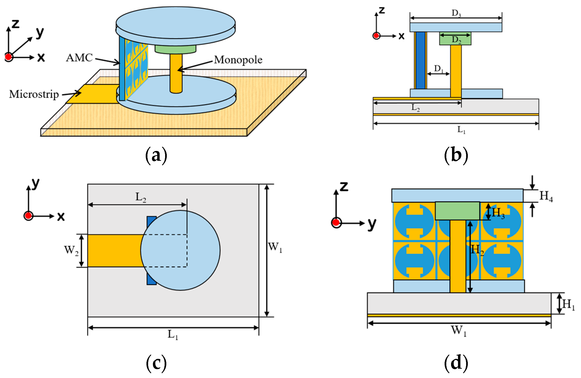
2.1. Directional Button Antenna
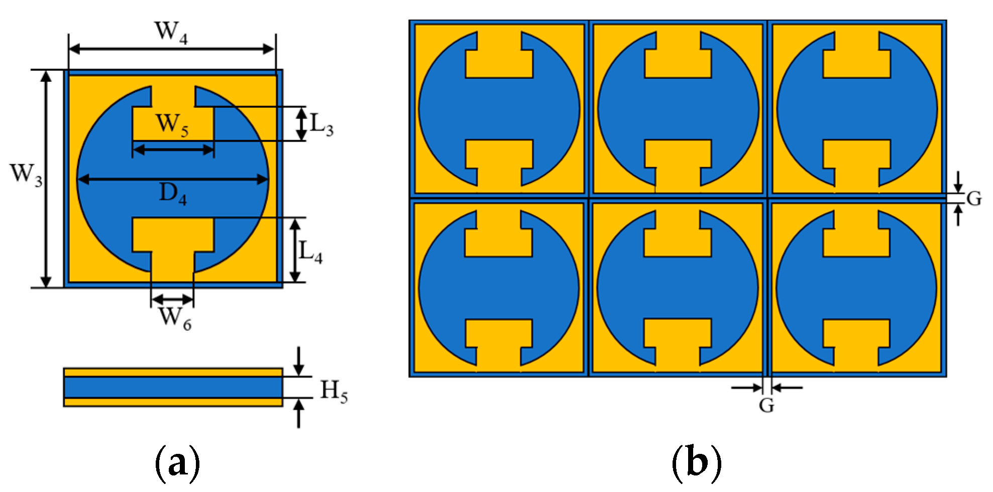
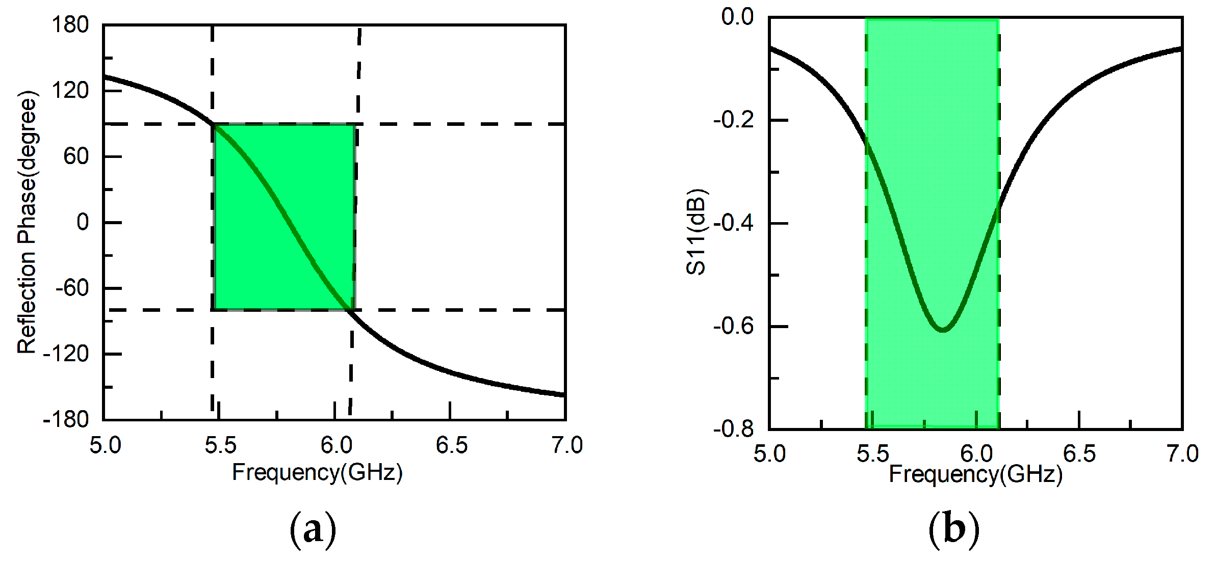
The directional button antenna comes from the conventional one but an AMC structure is added on the side of feeding. The whole configuration and the details are shown in Figure 1. Figure 1a shows that the antenna consists of three parts: the all-fabric microstrip line feed connected with the monopole, the AMC cells, and the radiator of the monopole with top- and bottom-loaded substrates, where the top loads reduce the height, while the main function of the bottom one is to fix the monopole. The final design should consider the mutual impacts of these three parts as a whole, but the AMC structure can be determined first to be the benchmark for the rest of the parts owing to depending on 5.8 GHz. Then, we used it to estimate the height of the monopole antenna and its loads. After these, the feeding of the all-fabric microstrip line was designed in order to realize a good match for the monopole antenna. The corresponding designs are depicted in detail as follows.

2.1.1. AMC Design

We used the same idea as in [35] to design the AMC structure and designed the formulas to determine the size [36]:
ω 0 = 1 L C        
L = μ H 5  
C = W 3 ε 0 ( 1 + ε r ) π c o s h 1 ( W 3 + G G )
where ω 0 is the resonant angular frequency, ε r is the relative permittivity of substrate, and L and C are the corresponding inductance and capacitance determined by the cell parameters of width W 3 , height H 5 , and gap G shown in Figure 2.
Therefore, the final AMC cell and the corresponding 2 × 3 structure applied for directional radiation are shown in Figure 2. The AMC cell has three layers as shown in Figure 2a, including the top layer of the resonant structure, the substrate, and the ground plane at the bottom. The material of the substrate is F4BTM with a thickness of 1.5 mm, and the permittivity and the loss tangent are 6.15 and 0.0045, respectively. After careful design, the values for the corresponding variables are listed in Table 1, and there exists a 0.2 mm gap between the adjacent cells for the final 2 × 3 structures, as shown in Figure 2b.
The corresponding reflection coefficients of the AMC cell are shown in Figure 3. From Figure 3a, we know that the phase difference is 180° in the band of 5.47 GHz to 6.11 GHz, which covers the concerned 5.8 GHz of ISM band. Additionally, the reflection amplitude is higher than −0.6 dB in this band, as in Figure 3b, indicating good reflection.

2.1.2. Monopole and Microstrip Line Designs

Depending on the above design of the AMC structure, the monopole antenna was determined next. To reduce the height of the monopole antenna for 5.8 GHz radiation, the substrate top-loaded technique was employed. The top substrate with blue color in Figure 1 is TP1020, the permittivity is 10.2, and the loss tangent is 0.0015. Another substrate below is FR4, which has a permittivity of 4.4 and a loss tangent of 0.025. At the bottom of the monopole, there is one blue substrate, which is the same as the top-loaded one. The main purpose is to fix the monopole and form the button shape.
One piece of conventional cylindrical copper with a diameter of 1.4 mm was selected as the radiator of the antenna and then combined with the above materials. We designed a monopole antenna resonating around 5.8 GHz. In order to obtain good matching for the antenna, an all-fabric quarter-wave transformer composed of a microstrip line was designed. The substrate is 100% cotton with a thickness of 1.5 mm; the permittivity and the loss tangent are 1.6 and 0.02, respectively. The conductive textile of the microstrip line is a composite of nickel and copper with a resistivity of about 0.05 Ω · m . Furthermore, the strip of the microstrip line, taken as the feeding, connects to the cylindrical copper. The final values of both the monopole and the microstrip line are listed in Table 2.

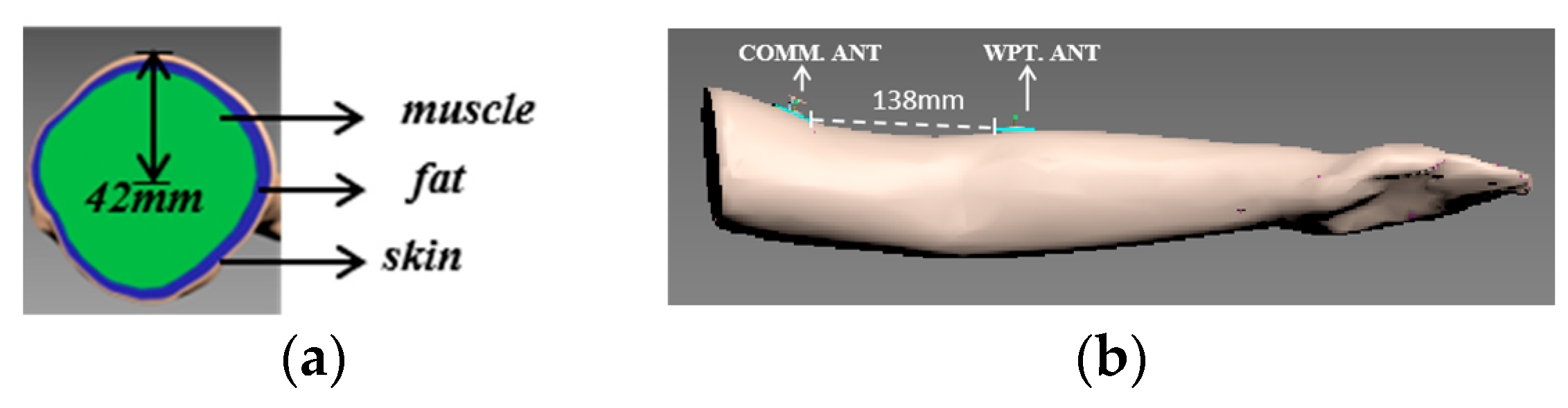
2.2. Real Electromagnetic Arm Model

The arm studied was the same as in [18], which belongs to a Chinese woman with the age of 25 years, a height of 165 cm, and a weight of 53 kg, but the Yagi-Uda antennas were replaced by the proposed button antennas. We show it in Figure 4. Here, the distance between the adjacent edges of button antennas is 138 mm, which is about 2.7 λ 0 . As in [18], we compared the on-arm measured S11s of the WPT antenna when the communication antenna was present or not. The results are shown in Figure 5a, from which we know that the existence of the communication antenna had little effect on the S11 of the WPT antenna. Then, we compare the simulated and the measured S21s in Figure 5b, where the difference for almost all of the frequencies is less than 3 dB. The reasons for the difference are: (1) practical antennas cannot be aligned so well as in a simulation, and (2) the complexities of both the arm and the wearable antenna cannot be accurately imitated by software.

3. Antenna Performance and On-Arm Measurement Method

The antenna performance without the arm is analyzed first, and the interactions between the arm and the antenna are compared in the next section by means of the proposed on-arm measurement method.

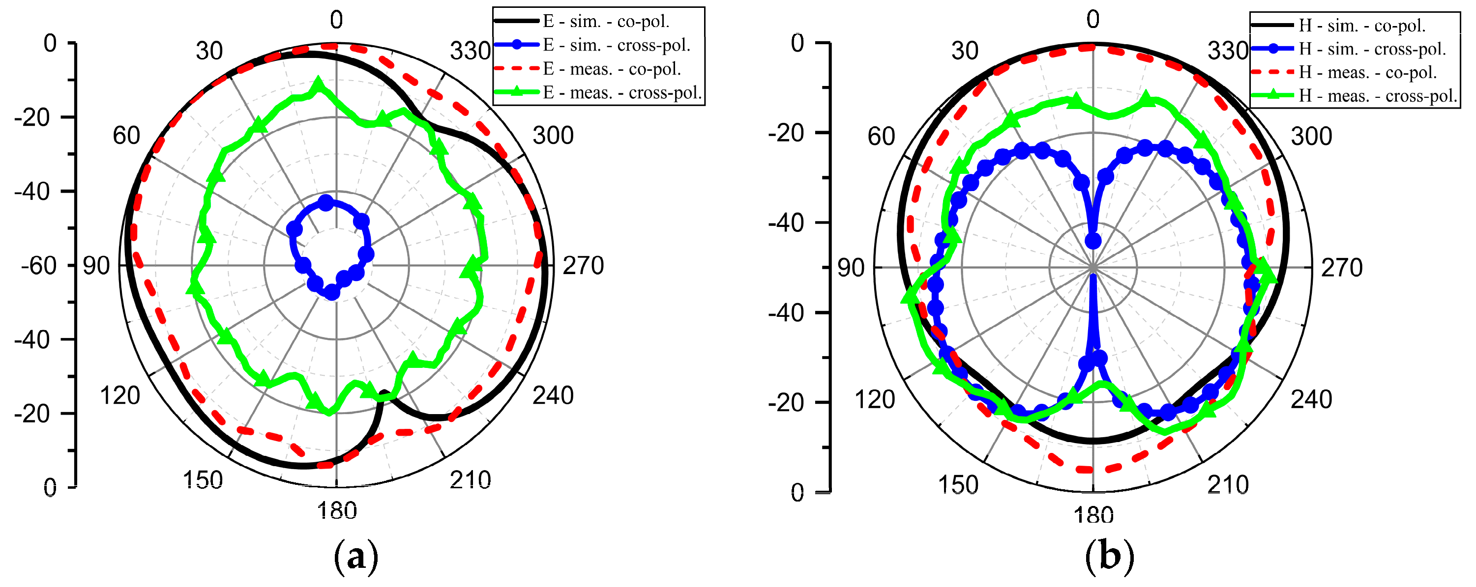
3.1. Antenna Performance Analysis

Two antenna prototypes were fabricated according to the aforementioned values; one of them is shown in Figure 6. Here, the all-fabric microstrip line was made by pasting the conductive textile with the proper size knife cut on the aforementioned 100% cotton substrate. Then, the bottom circular-disc substrate was put on the microstrip line, and the rest of the parts, including the monopole, the AMC cells, and the top-loaded substrates were finally determined. The corresponding radiation measurements were conducted in an anechoic chamber, which is shown in Figure 7. We give the E-plane measurement scheme in Figure 7a; we made a sloped foam for the H-plane measurement, as shown in Figure 7b, in order to capture the plane with the maximum value, where the slope detail is presented.
The comparison of simulated and measured S11s for the proposed antenna is shown in Figure 8. The measured bandwidth was 1.07 GHz, from 5.48 GHz to 6.55 GHz, which is much wider than that of the simulated 0.37 GHz starting from 5.65 GHz to 6.02 GHz. This often happens if the textile is taken as part of the antenna, as in [37,38], because we cannot accurately imitate textiles in models, which leads to an air-gap textile antenna having a lower quality factor and the consequent wide bandwidth. However, the concerned 5.80 GHz is still in the bandwidth. We also found the shift of resonances was 50 MHz, where the simulated value was 5.80 GHz and the measured was 5.85 GHz.
Comparisons of the normalized radiation patterns are shown in Figure 9. The E-plane comparison is shown in Figure 9a, while the H-plane comparison is depicted in Figure 9b. The co-polarization of the E-plane agrees well with that of the simulation; the measured cross-polarization is higher than that of the simulation, but most of the measured values were less than 20 dB compared with those of the co-polarization values. The H-plane pattern shows that the back radiation was significantly reduced owing to the presence of the ground plane on the microstrip line.
To further validate the design, we took the comparison of realized gains in Figure 10. The simulated results changed around 4 dB in the 5.80 GHz, and the difference at the same frequency between the simulation and measurement is less than 1 dB. The lower frequencies show significant differences due to the relatively non-uniform property of textiles.
Comparisons with the other works are listed in Table 3, where the work of [34] is not included because it is just a button-like antenna without a monopole or post in between, and the ‘height’ does not include the height of the substrate. From these comparisons, we know that different types of antennas are required to satisfy different requirements, and omnidirectional radiation is employed for on-body applications so that the gains are not high. However, the gain was up to 5.05 dB at 5.8 GHz in [33]. In fact, it is not real omnidirectional radiation as stated by the authors but directional. Our work focused on the on-body directional radiation of the button antenna to improve the transmission efficiency. The realized gain is higher than that of other works with omnidirectional patterns.

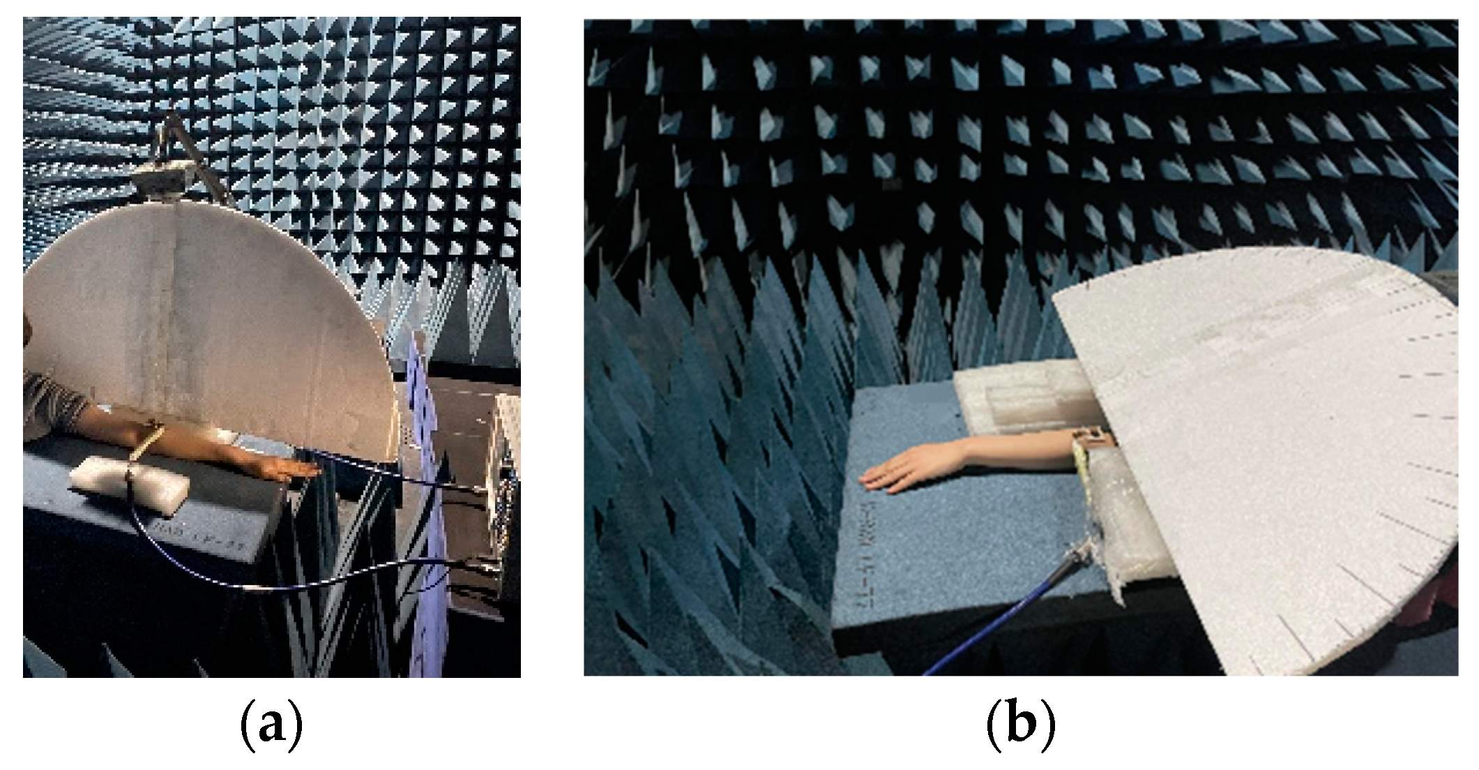
3.2. On-Arm Pattern Measurement Method

It was impossible to perform far-field measurements of the proposed antenna in an anechoic chamber on the conventional antennas due to the presence of the real arm. In other words, we could not freely move the real human body in the anechoic chamber. Furthermore, we could not rotate it, so we could not guarantee that the arm would not move, and the blocks of other human issues affect the measurement as well. Thus, we proposed an approximate far-field measurement scheme, which is shown in Figure 11, and the practical measurement is shown in Figure 12.
We used foam as the support to fix the antenna and placed the angular baseline on the foam to ensure accurate movement. The radius of the foam was about 10 λ 0 . This distance made the measurement approach far-field measurement, and the head did not affect the measurement at this distance. In Figure 12a, we fixed the foam vertically to the arm for the E-plane measurement and made a slope, which coincides with the simulation of the maximum for the H-plane measurement in Figure 12b.

4. Interactions between Antenna and Arm

Many researchers have proven that the radiation pattern is significantly affected when the antenna measurement is implemented on human tissue, as in [31]. We must face the fact that the situation of practical measurement is much more complex than that of a simulated model when the antenna is conformal to human tissue. However, we can obtain this difference by comparing the corresponding simulation and measurement to understand the influence of the antenna on human tissue.

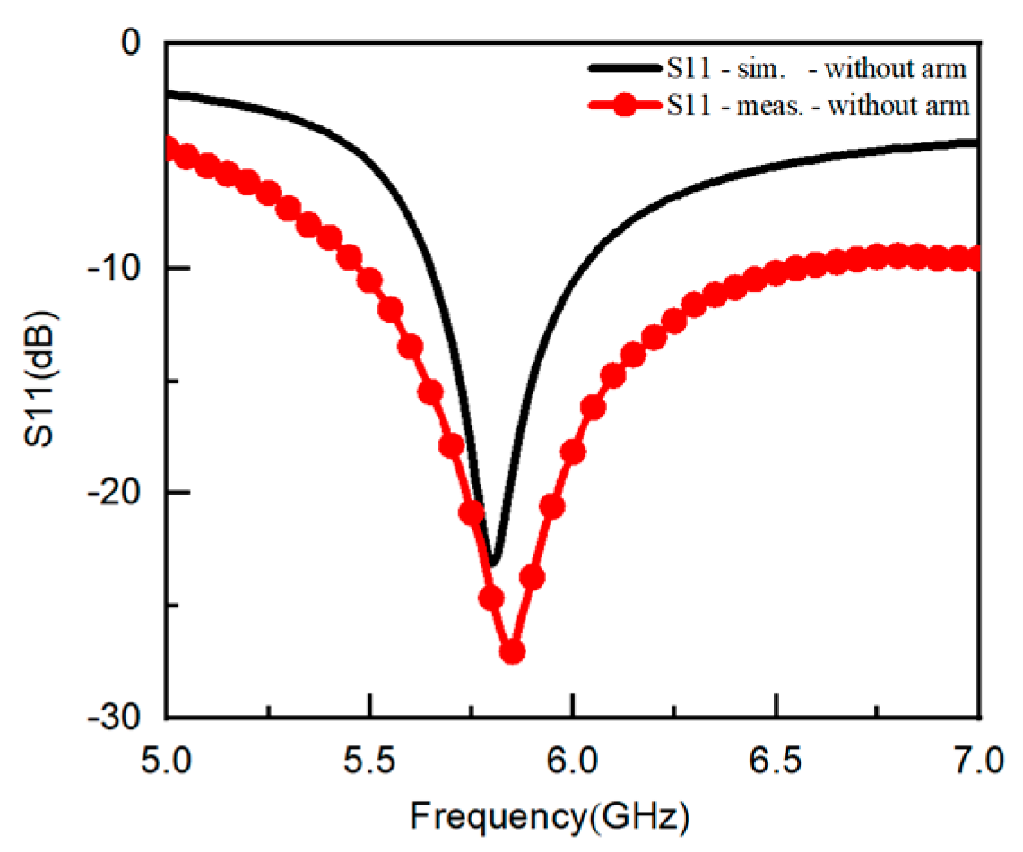
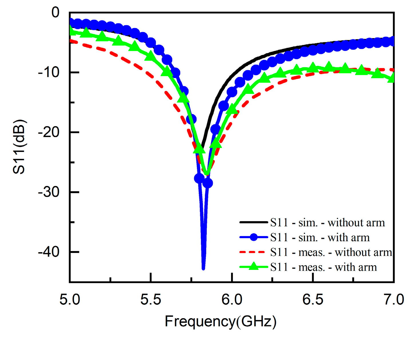
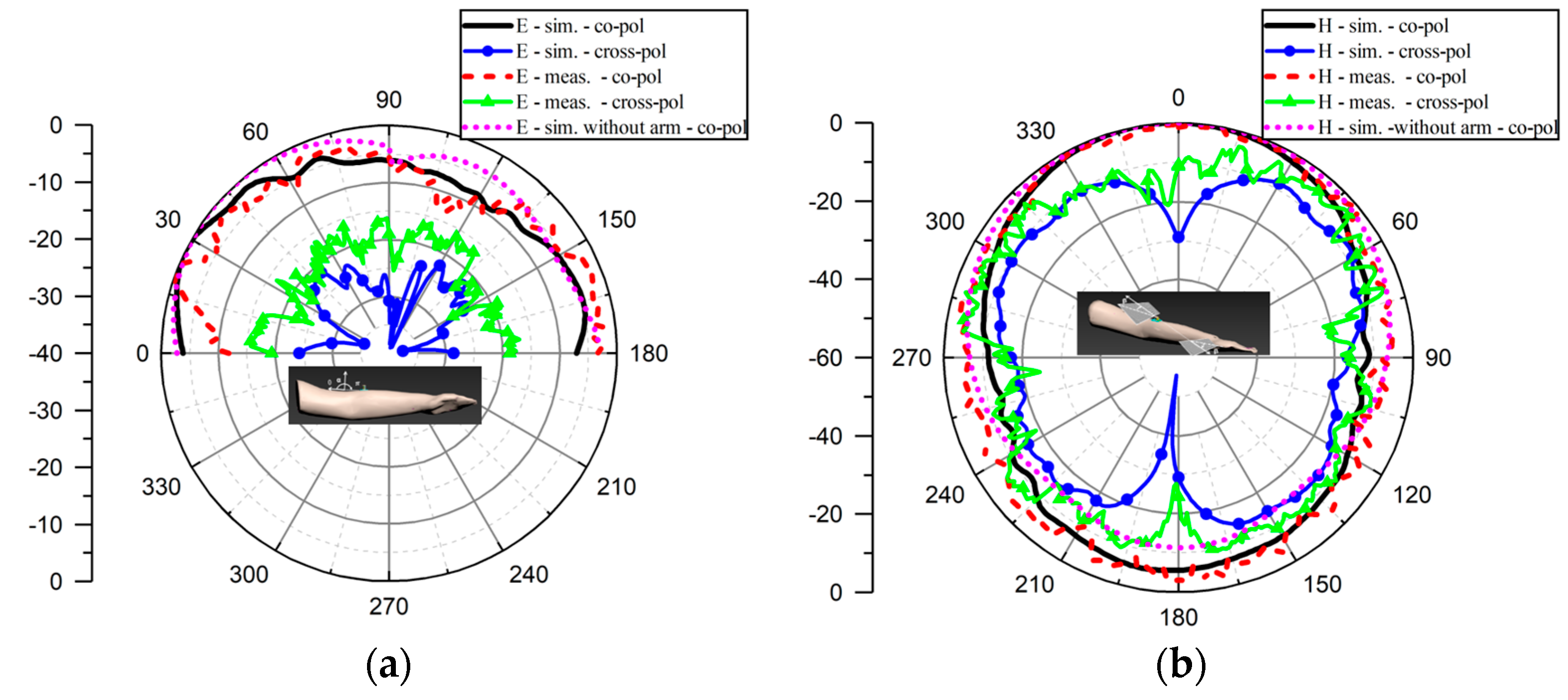
4.1. Arm Effect on Antenna

The finite size of the button antenna makes truncated current affect the arm or vice versa. The effect of an arm on the antenna performances was estimated by comparing S11 and the pattern. Comparisons of the simulated and measured S11s with/without an arm are shown in Figure 13, and the patterns are shown in Figure 14.
The simulated and the measured resonances show the resonant frequency was almost not affected by the arm. Here, the simulated resonance was 5.80 GHz without the arm and 5.82 GHz with the arm, and the corresponding measured resonances were 5.85 GHz and 5.84 GHz, respectively. We took the measured bandwidth as an example to depict the change in bandwidth because it was impossible to accurately imitate the textile antenna. It became narrower when the arm existed, which turned to 0.72 GHz (5.61 GHz~6.33 GHz) from 1.09 GHz (5.48 GHz~6.55 GHz).
In Figure 14, 0° corresponds to the α = β = 0° in Figure 11, and only half of the E-plane pattern above the arm is shown, from which we can judge the directional radiation. The results show that the on-arm measurements agree well with those of the simulations, even if just the approximate measurement is taken. This means that this method can be implemented to effectively measure on-arm far-field radiation. The measured maximum radiation of the E plane of Figure 14a is consistent with the simulation, indicating the coincidence of antenna alignment with the simulation. The largest difference appeared around 0 ° . That is because only the arm model existed in the simulation, while we could not ignore the presence of the head in the practical measurement. However, this difference does not affect the whole radiation performance. Additionally, we note that the differences in the E-plane patterns with and without the arm were significant, where we just present the simulated co-polarization pattern. The arm reduced the radiation above it, which means that the directional radiation was enhanced.
The H-plane pattern shows similar characteristics to those of the E-plane pattern, and they agree well. The arm has almost no effect on the upper half pattern in Figure 14b, which coincides with the radiation above the arm as exactly shown in Figure 12b. On the contrary, the radiation of the bottom half pattern, or the back radiation, was enhanced, which can be found in the beamwidth. This indicates that the arm plays a role in enhancing the radiation compared with that of a no-arm situation.

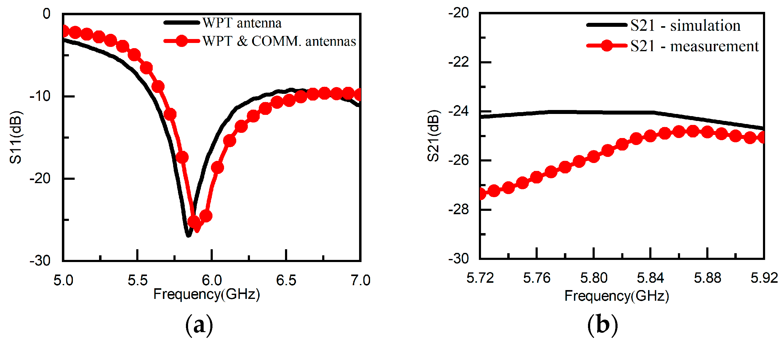
4.2. Transmission Efficiency

The measured S21s in Figure 5b shows the uptrend change with frequency. However, if we take 5.80 GHz as the benchmark to estimate the transmission efficiency, the errors for the rest of the frequencies are not too large. That is because the difference of S21s at other frequencies is less than 2 dB in the whole band. The corresponding transmission efficiency at 5.80 GHz for the transmission coefficient of −25.83 dB was calculated as 2.61 * 10 1 % , which is not too low considering only one antenna, and the distance of 2.7 λ 0 is much larger than that of the Yagi-Uda antennas in [18].

4.3. SAR: Antenna Effect on Arm

The validation of the above electromagnetic arm model helped us to estimate the effect of the antenna on the arm. Thus, we estimated the SAR of the on-arm simulated resonance as 5.84 GHz, and the input power was set to be 100 mW as in [39]. The maximum area was below the antenna due to the finite ground plane of the microstrip line making the truncated current significantly affect the arm. The average value of 1 g was 2.33 w/kg, which is higher than the 1.6 w/kg of the Federal Communications Commission (FCC) standard, but the 10 g value is lower than the standard, which is 0.777 w/kg versus 2 w/kg. This means there are non-uniform distributions of the induced field on the arm. On the contrary, the practical results are below the listed values because the simulated S21s were larger than the measured values, as shown in Figure 5b.

5. Conclusions

Depending on the present development trend of BAN, we developed an on-body WPT concept and used a directional button antenna, which is based on 2 × 3 AMC cells, to realize on-body wave propagation. The WPT antenna was placed on the elbow in order to imitate the collection of kinetic energy, and then the communication antenna placed on the upper arm was charged. A real female-arm electromagnetic model was built according to the measured transmission coefficient. Additionally, an approximate on-arm far-field measurement method was proposed taking into account the practical measurement environment. Then, two prototypes were fabricated, and the corresponding measurements with and without the arm were implemented and compared with the simulations. The validation of the antenna design was verified, and the interactions between the arm and the antenna were analyzed. The results showed that the arm affects not only the radiation pattern but also the resonance and bandwidth. The measured transmission efficiency was significantly improved compared with that of the Yagi-Uda antenna, and the SARs of the three layers were discussed at the standard of 100 mW.

Author Contributions

Conceptualization, A.M., Y.W. and O.M.R.; methodology, A.M., L.M., Y.X. (Yinfang Xu), and Y.W.; validation, Y.X. (Yuanzheng Xu) and Y.W.; writing—original draft preparation, Y.X. (Yuanzheng Xu) and Y.W.; writing—review and editing, O.M.R. All authors have read and agreed to the published version of the manuscript.

Funding

This research was funded by the Innovation Project of Guangxi Graduate Education of Guangxi Educational Committee, grant number YCSW2022292; National Natural Science Foundation of China, grant number 12161025; Guangxi Key Laboratory of Automatic Detecting Technology and Instruments of Guangxi Science and Technology Committee, grant number YQ22106.

Data Availability Statement

The data are contained within the article. The data presented in this study are available on request from the corresponding author.

Conflicts of Interest

The authors declare no conflict of interest.

References

  1. Glaser, P.E. Power from the Sun: Its Future. Science 1968, 162, 857–861. [Google Scholar] [CrossRef] [PubMed]
  2. Lin, J.C. Space Solar-Power Stations, Wireless Power Transmissions, and Biological Implications. IEEE Microw. Mag. 2002, 3, 36–42. [Google Scholar] [CrossRef]
  3. Sasaki, S.; Tanaka, K.; Maki, K.-I. Microwave Power Transmission Technologies for Solar Power Satellites. Proc. IEEE 2013, 101, 1438–1447. [Google Scholar] [CrossRef]
  4. Miller, J.M.; Onar, O.C.; Chinthavali, M. Primary-Side Power Flow Control of WirelessPower Transfer for Electric Vehicle Charging. IEEE J. Emerg. Sel. Top. Power Electron. 2015, 3, 147–162. [Google Scholar] [CrossRef]
  5. Oman, H. Electric car progress. IEEE Aerosp. Electron. Syst. Mag. 2002, 17, 30–35. [Google Scholar] [CrossRef]
  6. Re, P.D.H.; Podilchak, S.K.; Rotenberg, S.A.; Goussetis, G.; Lee, J. Circularly Polarized Retrodirective Antenna Array for Wireless Power Transmission. IEEE Trans. Antennas Propag. 2020, 68, 2743–2752. [Google Scholar]
  7. Ali, M.; Yang, G.; Dougal, R. A New Circularly Polarized Rectenna for Wireless Power Transmission and Data Communication. IEEE Antennas Wirel. Propag. Lett. 2005, 4, 205–208. [Google Scholar] [CrossRef] [Green Version]
  8. Olgun, U.; Chen, C.-C.; Volakis, J.L. Design of an efficient ambient WiFi energy harvesting system. IET Microw. Antennas Propag. 2012, 6, 1200–1206. [Google Scholar] [CrossRef]
  9. Chae, S.H.; Jeong, C.; Lim, S.H. Simultaneous Wireless Information and Power Transfer for Internet of Things Sensor Networks. IEEE Internet Things J. 2018, 5, 2829–2843. [Google Scholar] [CrossRef]
  10. Lin, W.; Ziolkowski, R.W. Electrically Small, Single-Substrate Huygens Dipole Rectenna for Ultracompact Wireless Power Transfer Applications. IEEE Trans. Antennas Propag. 2021, 69, 1130–1134. [Google Scholar] [CrossRef]
  11. Bito, J.; Hester, J.G.; Tentzeris, M.M. Ambient RF Energy Harvesting From a Two-Way Talk Radio for Flexible Wearable Wireless Sensor Devices Utilizing Inkjet Printing Technologies. IEEE Trans. Microw. Theory Tech. 2015, 63, 4533–4543. [Google Scholar] [CrossRef]
  12. Bao, K.; Zekios, C.L.; Georgakopoulos, S.V. A Wearable WPT System on Flexible Substrates. IEEE Antennas Wirel. Propag. Lett. 2019, 18, 931–935. [Google Scholar] [CrossRef]
  13. Vital, D.; Bhardwaj, S.; Volakis, J.L. Textile-Based Large Area RF-Power Harvesting System for Wearable Applications. IEEE Trans. Antennas Propag. 2020, 68, 2323–2331. [Google Scholar] [CrossRef]
  14. Yu, B.-Y.; Wang, Z.-H.; Ju, L.; Zhang, C.; Liu, Z.-G.; Tao, L.; Lu, W.-B. Flexible and Wearable Hybrid RF and Solar Energy Harvesting System. IEEE Trans. Antennas Propag. 2022, 70, 2223–2233. [Google Scholar] [CrossRef]
  15. Poon, A.S.Y.; O’Driscoll, S.; Meng, T.H. Optimal Frequency for Wireless Power Transmission Into Dispersive Tissue. IEEE Trans. Antennas Propag. 2010, 58, 1739–1750. [Google Scholar] [CrossRef] [Green Version]
  16. Kim, S.; Ho, J.S.; Poon, A.S.Y. Wireless Power Transfer to Miniature Implants: Transmitter Optimization. IEEE Trans. Antennas Propag. 2012, 60, 4838–4845. [Google Scholar] [CrossRef]
  17. Nguyen, N.; Ha-Van, N.; Seo, C. Midfield Wireless Power Transfer for Deep-Tissue Biomedical Implants. IEEE Antennas Wirel. Propag. Lett. 2020, 19, 2270–2274. [Google Scholar] [CrossRef]
  18. Wang, Y.; Xu, Y.; Wang, B.; Mo, I.; Safavi-Naeini, S. Wireless Power Transfer on Human Arm for Future Body Area Network. In Proceedings of the IEEE International Symposium on Antennas and Propagation (APSURSI), Singapore, 4–10 December 2021. [Google Scholar]
  19. Wang, Y.; Xu, Y.; Wang, B.; Mo, J.; Ramahi, O.M. A 24-GHz Directional Button Antenna for Wireless Power Transfer on Human Arm. In Proceedings of the IEEE International Symposium on Antennas and Propagation (APSURSI), Denver, CO, USA, 10–15 July 2022. [Google Scholar]
  20. Hertleer, C.; Tronquo, A.; Rogier, H.; Vallozzi, L.; Van Langenhove, L. Aperture-Coupled Patch Antenna for Integration Into Wearable Textile Systems. IEEE Antennas Wirel. Propag. Lett. 2007, 6, 392–395. [Google Scholar] [CrossRef] [Green Version]
  21. Roh, J.-S.; Chi, Y.-S.; Lee, J.-H.; Tak, Y.; Nam, S.; Kang, T.J. Embroidered Wearable Multiresonant Folded Dipole Antenna for FM Reception. IEEE Antennas Wirel. Propag. Lett. 2010, 9, 803–806. [Google Scholar] [CrossRef]
  22. Kim, S.; Ren, Y.-J.; Lee, H.; Rida, A.; Nikolaou, S.; Tentzeris, M.M. Monopole Antenna With Inkjet-Printed EBG Array on Paper Substrate for Wearable Applications. IEEE Antennas Wirel. Propag. Lett. 2012, 11, 663–666. [Google Scholar] [CrossRef] [Green Version]
  23. Gao, G.-P.; Hu, B.; Wang, S.-F.; Yang, C. Wearable Circular Ring Slot Antenna With EBG Structure for Wireless Body Area Network. IEEE Antennas Wirel. Propag. Lett. 2018, 17, 434–437. [Google Scholar] [CrossRef]
  24. Chahat, N.; Zhadobov, M.; Le Coq, L.; Sauleau, R. Wearable Endfire Textile Antenna for On-Body Communications at 60 GHz. IEEE Antennas Wirel. Propag. Lett. 2012, 11, 799–802. [Google Scholar] [CrossRef]
  25. Kaufmann, T.; Fumeaux, C. Wearable Textile Half-Mode Substrate-Integrated Cavity Antenna Using Embroidered Vias. IEEE Antennas Wirel. Propag. Lett. 2013, 12, 805–808. [Google Scholar] [CrossRef]
  26. Abbasi, Q.H.; Rehman, M.; Yang, X.; Alomainy, A.; Qaraqe, K.; Serpedin, E. Ultrawideband Band-Notched Flexible Antenna for Wearable Applications. IEEE Antennas Wirel. Propag. Lett. 2013, 12, 1606–1609. [Google Scholar] [CrossRef]
  27. Sanz-Izquierdo, B.; Miller, J.A.; Batchelor, J.C.; Sobhy, M.I. Dual-band wearable metallic button antennas and transmission in body area networks. IET Microw. Antennas Propag. 2010, 4, 182–190. [Google Scholar] [CrossRef]
  28. Xiaomu, H.; Yan, S.; Vandenbosch, G.A.E. Wearable Button Antenna for Dual-Band WLAN Applications With Combined on and off-Body Radiation Patterns. IEEE Trans. Antennas Propag. 2017, 65, 1384–1387. [Google Scholar] [CrossRef]
  29. Zhang, X.Y.; Wong, H.; Mo, T.; Cao, Y.F. Dual-Band Dual-Mode Button Antenna for On-Body and Off-Body Communications. IEEE Trans. Biomed. Circuits Syst. 2017, 11, 933–941. [Google Scholar] [CrossRef]
  30. Yin, X.; Chen, S.J.; Fumeaux, C. Wearable Dual-Band Dual-Polarization Button Antenna for WBAN Applications. IEEE Antennas Wirel. Propag. Lett. 2020, 19, 2240–2244. [Google Scholar] [CrossRef]
  31. Hu, X.; Yan, S.; Vandenbosch, G.A.E. Compact Circularly Polarized Wearable Button Antenna with Broadside Pattern for U-NII Worldwide Band Applications. IEEE Trans. Antennas Propag. 2019, 67, 1341–1345. [Google Scholar] [CrossRef]
  32. Hu, X.; Yan, S.; Zhang, J.; Volski, V.; Vandenbosch, G.A.E. Omni-Directional Circularly Polarized Button Antenna for 5 GHz WBAN Applications. IEEE Trans. Antennas Propag. 2021, 69, 5054–5059. [Google Scholar] [CrossRef]
  33. Le, T.T.; Kim, Y.-D.; Yun, T.-Y. Wearable Pattern-Diversity Dual-Polarized Button Antenna for Versatile On-/Off-Body Communications. IEEE Access 2022, 10, 98700–98711. [Google Scholar] [CrossRef]
  34. Sambandam, P.; Kanagasabai, M.; Natarajan, R.; Alsath, M.G.N.; Palaniswamy, S. Miniaturized Button-Like WBAN Antenna for Off-Body Communication. IEEE Trans. Antennas Propag. 2020, 68, 5228–5235. [Google Scholar] [CrossRef]
  35. Kyriazidou, C.A.; Contopanagos, H.F.; Alexopoulos, N.G. Alexopoulos. Space-Frequency Projection of Planar AMCs on Integrated Antennas for 60 GHz Radios. IEEE Trans. Antennas Propag. 2012, 60, 1899–1909. [Google Scholar] [CrossRef]
  36. Yang, F.; Rahmat-samii, Y. Electromagnetic Band Gap Structures in Antenna Engineering; Cambridge University Press: Cambridge, UK, 2008. [Google Scholar]
  37. Ashyap, A.Y.I.; Abidin, Z.Z.; Dahlan, S.H.; Majid, H.A.; Shah, S.M.; Kamarudin, M.R.; Alomainy, A. Compact and Low-Profile Textile EBG-Based Antenna for Wearable Medical Applications. IEEE Antennas Wirel. Propag. Lett. 2017, 16, 2550–2553. [Google Scholar] [CrossRef] [Green Version]
  38. Çelenk, E.; Tokan, N.T. All-Textile On-Body Antenna for Military Applications. IEEE Antennas Wirel. Propag. Lett. 2022, 21, 1065–1069. [Google Scholar] [CrossRef]
  39. El Atrash, M.; Abdalla, M.A.; Elhennawy, H.M. A Wearable Dual-Band Low Profile High Gain Low SAR Antenna AMC-Backed for WBAN Applications. IEEE Trans. Antennas Propag. 2019, 67, 6378–6388. [Google Scholar] [CrossRef]
Figure 1. The configuration and details: (a) the whole configuration, (b) the side view of zox-plane, (c) the top view of xoy-plane, and (d) the side view of yoz-plane.
Electronics 12 01758 g001
Figure 2. The AMC designs: (a) unit cell and (b) 2 × 3 structure.
Electronics 12 01758 g002
Figure 3. The reflection coefficients: (a) phase and (b) amplitude.
Electronics 12 01758 g003
Figure 4. Real female arm model: (a) three-layered structure and (b) arm and antennas.
Electronics 12 01758 g004
Figure 5. S parameters: (a) the measured S11s of WPT ANT w./wo. Comm. ANT and (b) S21.
Electronics 12 01758 g005
Figure 6. Antenna prototype.
Electronics 12 01758 g006
Figure 7. Measurements in anechoic chamber: (a) E plane and (b) H plane.
Electronics 12 01758 g007
Figure 8. The simulated and measured S11s.
Electronics 12 01758 g008
Figure 9. The comparison of simulated and measured normalized radiation patterns: (a) E-plane; (b) H-plane.
Electronics 12 01758 g009
Figure 10. The simulated and measured realized gains.
Electronics 12 01758 g010
Figure 11. The on-arm measurement sketches: (a) E plane and (b) H plane.
Electronics 12 01758 g011
Figure 12. The practical on-arm measurements: (a) E plane and (b) H plane.
Electronics 12 01758 g012
Figure 13. Measured S11s with/without arm.
Electronics 12 01758 g013
Figure 14. On-arm patterns: (a) E -plane and (b) H plane.
Electronics 12 01758 g014
Table 1. The values of AMC variables (unit: mm).
VariableW3W4W5W6L3
Value43.81.510.6
VariableL4D4H5G
Value1.23.61.50.2
Table 2. The values of monopole and microstrip line variables (unit: mm).
VariableW1W2L1L2D1D2
Value2563015.52.94
VariableD3H1H2H3H4
Value161.57.41.61
Table 3. Comparisons with other works (O: omnidirectional; D: directional).
Ref.f0
(GHz)
Radius
(mm)
Height
(mm)
ApplicationRadiatorPatternGain
(dBi)
[27]2.45
5
8 > 11.3On-body
Off-body
MonopoleO
D
1.2
2.9
[28]2.45
5.5
84.575On-body
Off-body
Monopole
Patch
O
D
1.05
6.04
[29]2.45
5.8
86.5On-body
Off-body
Inverted-FO
D
−0.6
4.3
[30]2.45
5.8
910On-body
Off-body
Monopole
Cross Dipole
O
D
2.2
8.6
[31]5.59.779Off-bodyLoopD3.5
[32]5.814.17.29On-bodyMagnetic Monopole and PatchO ~ 2.1
[33]2.45
3.7
5.8
UWB
1112.508On-body
Off-body
On-body
Off-body
Cross Dipole
Annular Ring
Annular Ring
Cross Dipole
O
D
O
D
1
6.6
5.05
6.5
This work5.8811.5On-bodyMonopoleD4
Disclaimer/Publisher’s Note: The statements, opinions and data contained in all publications are solely those of the individual author(s) and contributor(s) and not of MDPI and/or the editor(s). MDPI and/or the editor(s) disclaim responsibility for any injury to people or property resulting from any ideas, methods, instructions or products referred to in the content.

