Article

An Operation Scheme Generation Method for Nuclear Power Plant Operation under the Condition of No Operating Procedures Guided

1
College of Nuclear Science and Technology, Harbin Engineering University, Harbin 150001, China
2
College of Physics and Optoelectronic Engineering, Shenzhen University, Shenzhen 518061, China
3
Chinergy Co., Ltd., Beijing 100193, China
4
School of Electric Power Engineering, South China University of Technology, Guangzhou 510641, China
*
Author to whom correspondence should be addressed.
Electronics 2023, 12(8), 1836; https://doi.org/10.3390/electronics12081836
Submission received: 7 March 2023 / Revised: 6 April 2023 / Accepted: 10 April 2023 / Published: 12 April 2023
(This article belongs to the Section Systems & Control Engineering)

Abstract

:
Large-scale, complex, and high-risk industrial systems such as nuclear power plants have developed detailed operating procedures. Under the expected conditions, the operators operate the system according to the operating procedures to avoid human error. However, under complex and unfamiliar conditions, once the guidance of operating procedures is lost, serious consequences may be caused. This paper proposes a No-Procedure guided Operation Supervision Technology (NoP-OST). The key idea is to identify the success paths by a forward-searching approach from source to sink functions. On this basis, the success paths are combined to generate various operation schemes to achieve the main objectives of the system. The paper illustrates the application of NoP-OST through the case of loss of the Residual Heat Removal System (RHRS) in a Pressurized Water Reactor (PWR) nuclear power plant. The research results show that the method proposed in this paper can provide a valuable operational reference for complex systems by making use of the available functions of the system.

1. Introduction

Ensuring safety is the unswerving goal throughout the life cycle of nuclear power plants (NPPs), including design, construction, operation, maintenance, and decommissioning. Hardware failures and human errors constitute the main causes of operation events and accidents at NPPs. Among them, the incidents and accidents in the early NPPs are mainly attributed to hardware failure. After the introduction of new materials and technologies to improve the durability and reliability of equipment [1], the probability of hardware failure in NPPs has been significantly reduced, and human error has risen to be the causative factor in incidents and accidents at NPPs. According to the statistics of the NNSA (China National Nuclear Safety Administration) for 14 years [2,3,4,5,6,7,8,9,10,11,12,13,14,15], incidents caused by human error accounted for 51% and even reached 73.9% in 2016.
After the Three Mile Island (TMI) accident, the nuclear industry has been committed to reducing the load and human error of operators by various means, such as improving the automation level of NPPs, improving human-machine interfaces (HMI) and operating procedures, developing operator support systems (OSS), enhancing operator training, etc. [16]. After these efforts, the number of human errors caused by operators in normal operations has decreased year by year. However, the prevention of human error in unfamiliar conditions is still one of the types of research focuses [17]. One of the lessons learned from three serious nuclear accidents (namely, the Three Mile Island nuclear accident, the Chornobyl nuclear accident, and the Fukushima nuclear accident) is that the probability of operator human errors in completely unfamiliar environments will significantly increase [18]. According to the statistics of the incidents in the first seven years of operation of six new NPPs in China (as shown in Figure 1), it is found that although the total number of incidents has fluctuated in the first four years, the proportion of human error has increased year by year. In the following three years, the proportion of human error and the number of incidents showed a slow downward trend. This trend change is related to the operator’s unfamiliarity with the NPPs, unskilled operation, and the running-in with the NPPs at the initial stage of plant operation. Therefore, it is necessary and urgent to strengthen the supervision of operators in unfamiliar plant operating conditions.
NPPs generally conduct team cooperation through shift supervisor supervision and cross-validation among operators to reduce human error [19]. However, the members of the same operation team may have great relevance in terms of knowledge, skills, working environment, perception and decision-making ability, and fatigue degree. The performance of supervisors and operators may deteriorate at the same time, which will weaken the effect of operation supervision [20]. In recent years, the energy industry has begun to introduce various computer intelligent decision-making methods to improve the safety [21,22,23,24]. Computer intelligent supervision technology can make use of the advantages of massive memory, fast calculation, and never fatigue to make up for the deficiencies of operators and prevent human error.
In the previous study, the author proposed the Operating Procedures Supervision System (OPSS) to implement operator supervision under the guidance of operating procedures [25]. Operating procedures are a group of actions with a time sequence, according to which the NPP operators can establish or maintain the functions of systems and equipment to achieve specific operational objectives. Each operating procedure is not the only means to achieve an operational objective, but an operation strategy that has been verified and proved to be safe, reliable, easy to implement, and can achieve the operation objective under an expected condition. However, under some special conditions, the operators may be in a situation where there is no operating procedure available, or all operating procedures are not fully applicable. In the absence of operating procedure guidance, the probability of operator error will increase. After the Fukushima nuclear accident, the Nuclear Energy Institute (NEI) put forward the FLEX strategy (Diverse and Flexible Coping Strategies) [26], which aims to establish the ability to prevent fuel and spent fuel from damage and maintain the containment function for a long time by using fixed equipment, on-site mobile equipment and preset off-site resources.
Operators utilize various knowledge to identify available systems, equipment, and functions to achieve operational objectives in unfamiliar NPP operation conditions, and therefore bear the high cognitive load and are prone to human error. This paper proposes a No-Procedure guided Operation Supervision Technology (NoP-OST) based on the system function model to help operators understand the system operation objectives, available functions, and equipment, automatically identify the reference path to achieve the operational objectives and achieve the purpose of reducing human error.
The following chapters are arranged as follows: Section 2 presents the method of the NoP-OST; a case is given in Section 3 to illustrate the use of the NoP-OST; the characteristics of the NoP-OST are discussed and summarized in the last chapter.

2. Design of NoP-OST
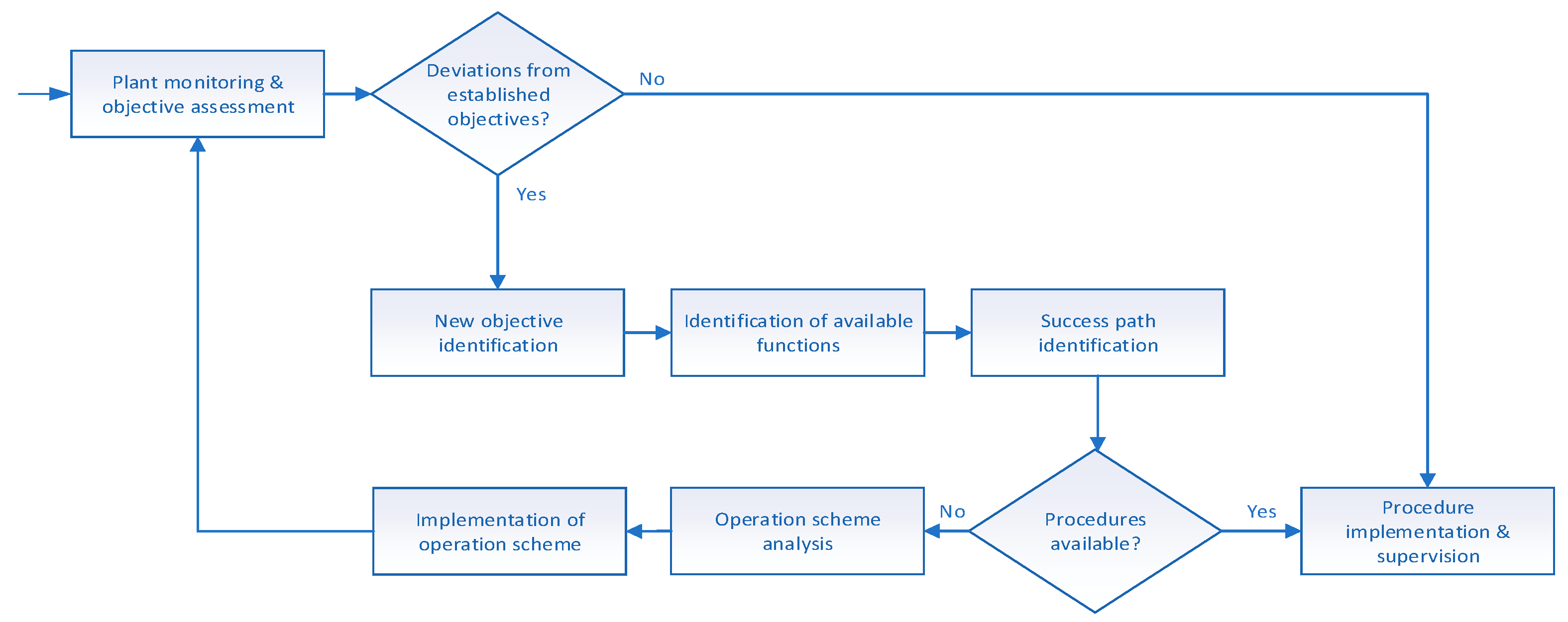
2.1. Overall Design

Figure 2 shows the functional block diagram of the overall design of NoP-OST. The NoP-OST starts with plant operation monitoring which monitors the performance of the critical systems and equipment and analyzes whether the plant operation deviates from the objectives to be achieved. If there is no deviation, it means that the current operating procedures are still applicable, and the current operation strategy is to implement and monitor the established operation procedures. If the current plant operation deviates from the operation objectives, the established operating procedures may not be applicable, and the new operation objective of the plant needs to be identified. Once the new operation objectives are determined, the next step is to analyze the available functions to identify which plant functions are still effective and can be used to achieve the operational objectives. It is worth noting that the available functions include those defined in the plant design, such as engineered safety features (ESF), as well as the potential capabilities of systems and equipment. These potential capabilities are inherent in the systems and equipment. Although they are not clearly defined in the design of an NPP, they can be utilized to play a substitute role for designed functions under special operating conditions. Under specific conditions, the available functions of the plant can be organized to form one or more success paths to achieve the operational objectives. It should also be noted that operating procedures are only part of these success paths. The difference between operating procedures and other success paths is that operating procedures are usually success paths that have been verified and validated to be reliable and easy to implement. If there are available operating procedures under the current operation objectives, it should be the first choice to implement the operating procedures and monitor the implementation of the operating procedures. In this case, the achievement of the operating objectives is credible.
In the absence of available operating procedures, the identified success paths can be used as a reference for formulating various operation schemes. The implementation of the operation scheme is to take specific control actions to operate the systems and equipment to establish one or several successful paths, and finally achieve the operation objectives.

2.2. Success Path Identification Method

How to identify the success paths by utilizing the available functions to achieve the operational objectives is a key issue of NoP-OST. This paper adopts a Flow-based functional modeling approach [27] to describe the relationship between available functions and operational objectives. Flow-based approaches model a system by focusing on the flows (of mass, energy, or information) in the system and on the component actions on the considered flows [28]. In the NoP-OST, Multilevel Flow Modeling (MFM) is selected to build various system models of NPP. As shown in Figure 3, MFM provides common basic functions, such as source, sink, transport, barrier, storage, and balance, for representing mass, energy, and information [29]. Instances of these functions are connected to build function structures (i.e., flow structures). Functions can be linked to objectives (i.e., purposes of the system) by means-ends relations, representing that a set of functions are used to achieve the objectives. An objective can be also linked to functions, representing that the objective must be fulfilled for the functions to be available. The latest development of MFM provides control functions [30]. MFM has been usually applied as a cause-consequence reasoning technique for the purposes of fault diagnosis or alarm analysis of process systems including NPP, where the means-ends analysis strategy is commonly used. Starting from the objectives and through a top-down and backward-searching approach, the causal paths that endanger the achievement of the objectives in an MFM model are identified [31,32,33,34]. The application of MFM also serves for hazard analysis, which adopts a forward analysis method. The impact of an abnormal function on the objectives is analyzed and reasoned by utilizing a bottom-up and forward reasoning approach [35]. Yang [36] presents a method of utilizing MFM for quantitative reliability analysis. Song [37] proposed an MFM-based operation search method for planning the operation of complex process units. Recently, a model and rule-based operational process synthesis (OPS) system is proposed from the perspective of functional state transition [38].
Each MFM element of MFM represents a category of process phenomenon that can be mathematically represented. The mathematical expressions of some MFM functions which will be used later in this article are provided by Formulas (1)–(4), corresponding to the storage, balance, transport, and barrier functions, respectively. Further information on the mathematical basis of MFM elements can be found in reference [29]:
dv dt = F i F o
F i = F o
F i = F o
F o = 0
where F i   ,   F o   , and v represents the input, output, and accumulated quantity of a physical component, respectively.
The principle of success path identification based on MFM models is illustrated in Figure 4. The model shown in Figure 4 is a hypothetical MFM model that is not specific to specific objects. In this model, the system objective (obj) is realized by a flow structure composed of two sources (sou1 and sou2), two sinks (sin1 and sin2), and four transport functions (tra1, tra2, tra3, and tra4). It is further assumed that the objective obj is achieved by either sub-objective obj1 or obj2 which are directly implemented by the functions tra3 and tra4, respectively.
The available functions shall be identified before the successful path identification. The available function identification proceeds downwards from the objective obj, via the means-ends relation, into the connected flow network of functions, each of which is investigated (by sensor reading or on-site measurement) to find out whether it is available or not. In this example, it is assumed that the tra3 function is not available.
The success path identification starts from each source function and is analyzed forward along the flow direction. If the current path (the smallest one consists of one source function) has an available downstream function (except for storage and balance functions), the current path and downstream functions are connected to form a new path. Repeat this process repeatedly until the path reaches a sink function, thus forming a complete path from the source function to the sink function. If the downstream function of the current path is a storage or balance function (these two types of MFM functions can have multiple outputs), connect the storage or balance function to the current path, and copy the new path according to the output number of the storage or balance function, so that each new path corresponds to the output of the storage or balance function. Figure 5 shows the four complete paths of the MFM model shown in Figure 4 identified by this method. Among them, both path 1 and path 3 contain the unavailable tra3. Therefore, these two paths are not success paths unless tra3 can be recovered, and paths 2 and 4 are success paths.

3. Case Study

The Residual Heat Removal System (RHRS) is the main cooling means for Pressurized Water Reactor (PWR) nuclear power plant during the shutdown. This paper describes the NoP-OST with the loss of cooling of the RHRS incident of a PWR after reactor shutdown as an example. Figure 6 shows the structure of the RHRS (marked with the red line in the figure) and other related reactor cooling functions. The description of the relevant equipment in Figure 6 is given in Table 1. The main functions of the RHRS are as follows:
(1)
When the secondary loop is out of service, the RHRS removes the shutdown residual heat of the core and the sensible heat of the primary, loop coolant, and equipment.
(2)
When the reactor is in the shutdown state for loading, unloading, or maintenance, the RHRS removes the residual heat of the core and maintains the primary loop at a low temperature.
(3)
During the reactor start-up, the RHRS ensures the circulation of the primary loop coolant.
Figure 6. The structure of RHRS and the associated system of a PWR. The red part in the Figure 6 represents the failed of RHR system.
Electronics 12 01836 g006
Table 1. Description of the equipment in Figure 6.
No.EquipmentExplanation
1SGSteam generator
2RCPReactor coolant pump
3RCP212VPPrimary loop motor-driven valve
4RRA001VPRHRS motor-driven valve
5RRA001PORHRS pump
6RRA014VPRHRS motor-driven valve
7VBSteam bypass isolation valve
8RWSTRefueling water storage tank (RWST)
9005FIFloor sump filter
10006FIFloor sump filter
11014VBFloor sump manual isolation valve
12RIS051VPSafety Injection System (SIS) motor-driven valve
13RIS001VBSIS isolation valve
14RIS075VBSIS isolation valve
15RIS001POLow-pressure safety injection pump
16063VPPrimary loop motor-driven valve
17RCV001POHigh-pressure safety injection pump
18021VPPrimary loop motor-driven valve
19032VPSafety Injection Tank (SIT) motor-driven valve

3.1. Objective Identification

During the reactor shutdown, the core residual heat is mainly discharged by the RHRS to maintain the primary loop temperature. This paper selects the most extreme case, that is, the complete failure of the RHRS, to explain the application of the NoP-OST.
The RHRS failure indicates the core has lost cooling. In this case, the main objective of NPP is “to maintain the cooling capacity” to lower the primary loop temperature.
In addition to the RHRS, the additional core cooling function can be provided by Safety Injection System (SIS) and the secondary loop.
The SIS provides the following three sources of coolant:
(1)
Safety Injection Tank (SIT).
(2)
Refueling water storage tank (RWST).
(3)
Floor sump.
The SIS injects water into the primary pool to cool the reactor in the following three ways:
(1)
Pressure of SIT: the SIT is filled with high-pressure helium. When necessary, the coolant in SIT can be pumped into the primary loop according to the pressure difference between SIT and the primary loop.
(2)
High-pressure safety injection pump (RCV001PO): the coolant in the RWST is pumped into the primary loop through forced circulation.
(2)
Low-pressure safety injection pump (RIS001PO): the coolant in the floor sump and RWST is pumped into the primary loop through forced circulation.

3.2. MFM of Maintaining Reactor Core Cooling

According to the selected operation objective (i.e., maintaining reactor core cooling), the MFM model is given, as shown in Figure 7.
The red part in the Figure 7 represents the failed of RHR system.
Table 2 shows the explanation of each main model element. The MFM model consists of four flow structures.
(1)
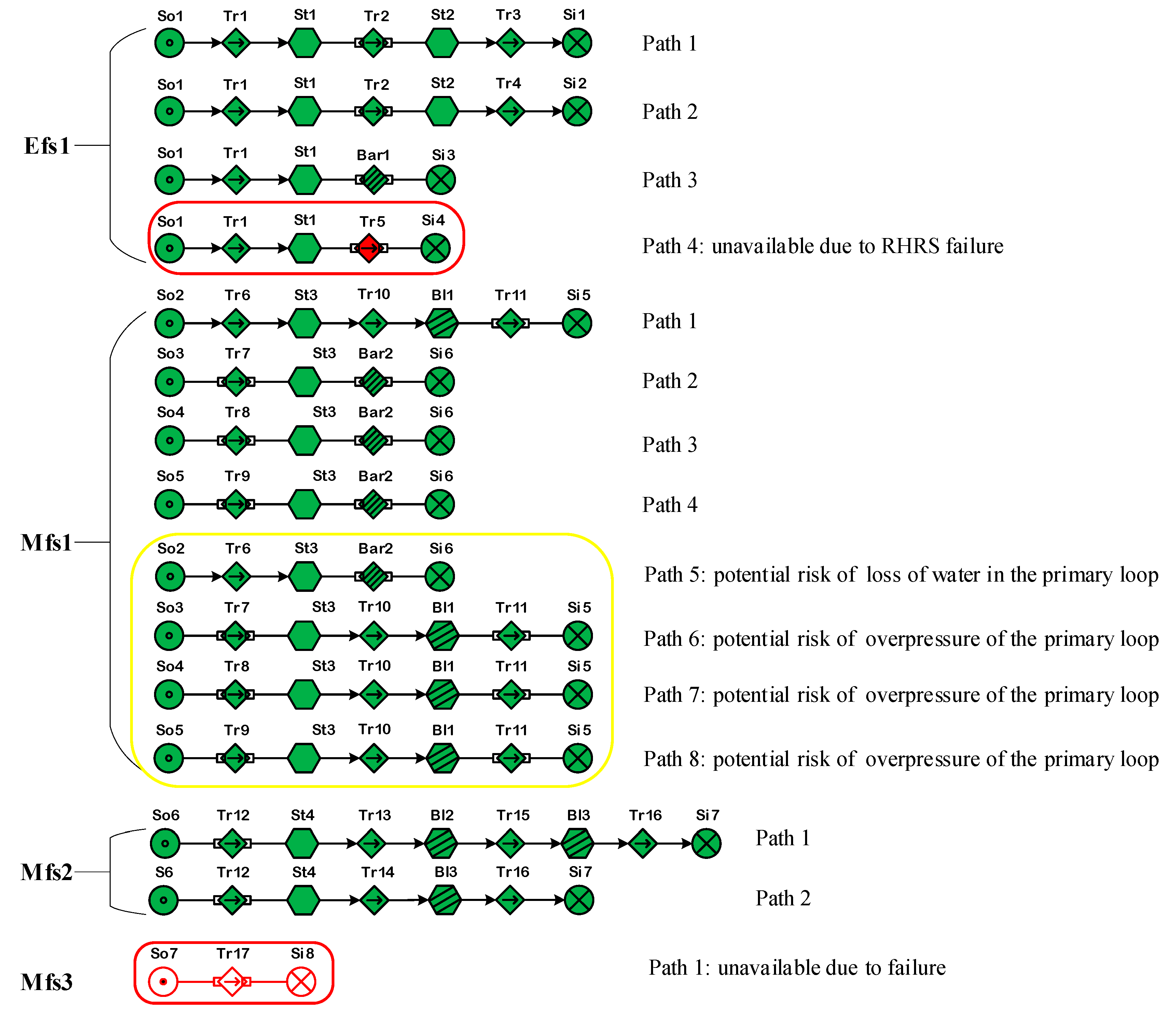
Efs1: is an energy flow for maintaining core cooling by removing the heat generated by the reactor (to achieve the objective obj0).
(2)
Mfs1: is a mass flow for providing enough coolant in the primary loop (to achieve the objective obj1).
(3)
Mfs2: is a mass flow for providing enough feedwater in the secondary loop (to achieve the objective obj2).
(4)
Mfs3: is a mass flow for driving the coolant flow in the RHRS (to achieve the objective obj3). Since the RHRS is assumed to fail, this mass flow is simplified to a higher degree.
Table 2. The explanation of the main MFM elements in Figure 7.
IDFunction DescriptionNotes
Obj0Maintain reactor core coolingMain objective
Obj1Maintain primary coolant flowBy the primary loop and supporting facilities
Obj2Maintain secondary coolant flowBy the secondary loop
Obj3Coolant supply from the RHRSBy the RHRS
So1Reactor core heat generation
So2Primary coolant supply
So3Coolant supply for high-pressure SISBy the SIT
So4Coolant supply for high-pressure or low-pressure SISBy the RWST
So5Coolant supply for reactor long-term coolingBy the floor sump
So6Coolant supply for the secondary loop
So7Coolant supply for the RHRSBy the primary loop
Si1Heat consumption through turbine work
Si2Heat consumption in the condenser
Si3Heat consumption in the floor sump
Si4Heat consumption in the RHRS
Si5Primary coolant flows back to the cold-leg pipe section
Si6Primary coolant flows into the floor sump
Si7Secondary coolant flows into the condenser
Si8Coolant injects into the primary loop
Tr1Heat transfer from fuel to the primary loop
Tr2Heat transfer from the primary loop to the SGBy the RCP
Tr3Heat transfer from the SG to the turbine
Tr4Heat transfer from the SG to the condenserVia the VB
Tr5Heat transfer from the primary loop to the RHRS
Tr6Primary coolant flows to the reactor vessel
Tr7Coolant flows to the reactor vesselVia high-pressure SIS
Tr8Coolant flows to the reactor vesselVia low-pressure SIS
Tr9Coolant flows to the reactor vesselVia circulating cooling pipelines
Tr10Primary coolant flows to the SG
Tr11Primary coolant flows to the cold-leg pipe sectionBy the RCP
Tr12Secondary coolant flows to the SG
Tr13Secondary coolant flows to the turbine
Tr14Secondary coolant flows to the condenserFrom the VB
Tr15Secondary coolant flows to the condenserFrom the turbine
Tr16Secondary coolant flows to the condenserFrom the turbine or SG
Tr17Coolant flows to the primary loopBy the RHRS
St1Heat storage in the primary loopBy primary coolant system
St2Heat storage in the SGBy steam generator
St3Coolant storage in the reactor vesselBy reactor vessel
St4Coolant storage in the SGBy steam generator (secondary side)
Bl1Coolant flows in the SGPrimary loop side
Bl2Flow connection between Tr13 and Tr15By pipeline
Bl3Flow connection between Tr14 and Tr15By pipeline
Bar1Prevent the primary loop from injecting the heat into the floor sumpBy the discharge valve
Bar2Prevent the primary loop from injecting coolant into the floor sumpBy the discharge valve

3.3. Success Path Identification

By using the method proposed in Section 2.2, the MFM model shown in Figure 7 is analyzed, and the successful paths are shown in Figure 8. As shown in Figure 8, the energy flow Efs1 contains 4 paths, and the mass flow Mfs1, Mfs2, and Mfs3 contain paths 8, 2, and 1, respectively. The physical meaning of each path is shown in Table 3. According to the assumption, the path corresponding to Mfs3 is unavailable, which also leads to the unavailability of Tr5 and path 4 in the Efs1 (which contains the unavailable Tr5).
Among the eight paths contained in Mfs1, paths 5–8 have obvious hazard consequences. If these hazard consequences cannot be dealt with well, the corresponding paths cannot be considered engineering solutions.
The path in the red boxes is not available, the path in the yellow boxes have hidden danger.
Based on the above analysis, six success paths are finally identified from the MFM model shown in Figure 7, which are summarized in Table 4. The success paths 1-1 and 2-1 need to establish the primary and secondary mass flow, that is, these two success paths contain one energy flow and two mass flows respectively. Other success paths only include one energy flow and one mass flow. The success path 4-1 is assumed to be a failure in this paper. If the failure can be corrected, then the path is available. Figure 9 shows the flows of mass and energy required for various success paths.

3.4. Operation Scheme Analysis

The success path 1-1 can well meet the demand for reactor core cooling and generate additional power supply. However, it should be noted that when the temperature of the primary loop becomes too low, the unsaturated steam generated in the SG may damage the turbine blades and reduce the life of the turbine. The success path 2-1 can well meet the cooling demand without additional negative effects. In the success paths 3-1, SIT stores low-temperature coolant. However, due to its limited volume, it is difficult for the SIT to provide cooling for a long time. As for the success path 3-2, although the RWST stores a considerable amount of coolant, it is still difficult to provide cooling for a long time. The success path 3.3 establishes a coolant circulation between the primary loop and the floor sump. The heat exchanger can be used for long-term cooling with the environment, so it can be used for long-term reactor core cooling. However, paths 3-1, 3-2 and 3-3 should not be selected unless necessary, because they may cause overpressure in the primary loop and damage the integrity of the primary loop.
Therefore, based on the advantages and disadvantages of the above success paths, it is suggested that the priority of the implementation of the operation plan should be the success path 2-1, path 1-1, path 3-3, path 3-2, and path 3-1.

4. Discussion and Conclusions

Nuclear power plants usually develop operating procedures for various working conditions, and operators can skillfully implement the procedures to avoid human errors. The Three Mile Island and Fukushima nuclear accidents have revealed that serious consequences will occur if operators have no operating procedure guidance under unfamiliar conditions. In this context, some international organizations, including the IAEA and the NEA, have proposed evaluating the defense in depth of NPPs and enhancing their ability to respond to severe accidents [39,40].
This paper proposes a No-Procedure guided Operation Supervision Technology (NoP-OST) which can be used to assist operators to establish various reasonable operation schemes under unfamiliar operating conditions of NPPs. A success path identification method is proposed. This paper selects MFM as the system modeling approach because this method can well meet the characteristics of NPPs in achieving safety and economic objectives by establishing various mass, energy, and information flows. The success paths are identified according to the structure of a set of functional MFM models which reflect the dependency between objectives and functions of specific plant systems. MFM models the system at different levels of means-ends, which is conducive to simplifying the identification of success paths to achieve the system objectives.
The success path identification by MFM commonly employs a means-end analysis approach which involves a top-down and backward searching from the objectives of MFM models. This strategy assumes that the MFM models have already well-established the correlation between system objectives and functions through task analysis.
In this paper, the search for success paths starts from a source function and proceeds with forward searching until a sink function is reached. This is because NPPs always achieve their operational objectives by providing material, energy, and information channels. This strategy cannot guarantee that the identified success paths will necessarily achieve the system’s objectives but can maximize the identification of success paths within the model’s scope. This is because the paper assumes that some success paths that were considered impossible or difficult to implement in the design phase may have been ignored during MFM modeling. However, under specific operating conditions, these paths can provide a technical means to ensure nuclear safety. As shown in the case study, the original purpose of the safety injection system was to supplement the coolant in the primary loop. However, through analysis, it was found that the injection system, along with the use of the discharge valve, can provide a certain cooling capacity. Therefore, a key point of the proposed method is that it is necessary to carry out operation scheme analysis by plant personnel to form various alternatives to achieve the main objectives by combining various success paths. As the case study shows, some success paths have preconditions or harmful consequences for implementation, which have not yet been reflected in the MFM model, and additional information needs to be supplemented by engineering experience or other methods such as by a full-scale simulator of the NPP. In other words, the proposed NoP-OST is currently a semi-automated framework that requires combining domain knowledge with automatic success path identification to form applicable operation schemes.

Author Contributions

Conceptualization, M.Y.; methodology, X.D. and M.Y.; validation, J.W.; formal analysis, X.D. and Z.D.; investigation, Z.D.; resources, J.W.; data curation, X.D.; writing—original draft preparation, X.D.; writing—review and editing, M.Y. and J.W.; supervision, H.W.; project administration, M.Y.; funding acquisition, M.Y. and J.W. All authors have read and agreed to the published version of the manuscript.

Funding

This research was supported by the College Students’ Innovative Entrepreneurial Training Program under Shenzhen University Contract No. S202210590089, the Teaching Reform Research Program under Shenzhen University Contract No. JG2022072, the Scientific Research Startup Program under Shenzhen University Contract No. 000002112214, and the Stable Support Plan Program under Shenzhen Natural Science Fund Contract No. 20220810124935001. This research was also supported by the Young Teacher Scientific Research Startup Program under Shenzhen University Contract No. 000002112211, and the Stable Support Plan Program under Shenzhen Natural Science Fund Contract No. 20220811012323001.

Data Availability Statement

Data is contained within the article.

Conflicts of Interest

The authors declare no conflict of interest.

References

  1. Lessons Learned from the Fukushima Nuclear Accident for Improving Safety of U.S. Nuclear Plants; National Academies Press: Washington, DC, USA, 2014.
  2. The People’s Republic of China National Nuclear Safety Administration 2006 Annual Report; National Nuclear Safety Administration: Beijing, China, 2006.
  3. The People’s Republic of China National Nuclear Safety Administration 2007 Annual Report; National Nuclear Safety Administration: Beijing, China, 2007.
  4. The People’s Republic of China National Nuclear Safety Administration 2008 Annual Report; National Nuclear Safety Administration: Beijing, China, 2008.
  5. The People’s Republic of China National Nuclear Safety Administration 2009 Annual Report; National Nuclear Safety Administration: Beijing, China, 2009.
  6. The People’s Republic of China National Nuclear Safety Administration 2010 Annual Report; National Nuclear Safety Administration: Beijing, China, 2010.
  7. The People’s Republic of China National Nuclear Safety Administration 2011 Annual Report; National Nuclear Safety Administration: Beijing, China, 2011.
  8. The People’s Republic of China National Nuclear Safety Administration 2012 Annual Report; National Nuclear Safety Administration: Beijing, China, 2012.
  9. The People’s Republic of China National Nuclear Safety Administration 2013 Annual Report; National Nuclear Safety Administration: Beijing, China, 2013.
  10. The People’s Republic of China National Nuclear Safety Administration 2014 Annual Report; National Nuclear Safety Administration: Beijing, China, 2014.
  11. The People’s Republic of China National Nuclear Safety Administration 2015 Annual Report; National Nuclear Safety Administration: Beijing, China, 2015.
  12. The People’s Republic of China National Nuclear Safety Administration 2016 Annual Report; National Nuclear Safety Administration: Beijing, China, 2016.
  13. The People’s Republic of China National Nuclear Safety Administration 2017 Annual Report; National Nuclear Safety Administration: Beijing, China, 2017.
  14. The People’s Republic of China National Nuclear Safety Administration 2018 Annual Report; National Nuclear Safety Administration: Beijing, China, 2018.
  15. The People’s Republic of China National Nuclear Safety Administration 2019 Annual Report; National Nuclear Safety Administration: Beijing, China, 2019.
  16. Jeon, I.; Yoon, H.J.; Kang, H.G. Feasibility estimation of new mitigation system through causal inference analysis with the functional model. Ann. Nucl. Energy 2020, 137, 107087. [Google Scholar] [CrossRef]
  17. Human Performance Improvement Handbook, Part 1, Volume 1; Department of Energy: Washington, DC, USA, 2009.
  18. Walker, J.S. Three mile island and Fukushima: Some reflections on the history of nuclear power. Reflect. Fukushima Daiichi Nucl. Accid. Towar. Soc. Sci. Lit. Eng. Resil. 2015, 215–221. [Google Scholar] [CrossRef] [Green Version]
  19. Montmayeul, R.; Mosnerondupin, F.; Llory, M. The Managerial Dilemma Between the Prescribed Task and the Real Activity of Operators—Some Trends for Research on Human-factors. Reliab. Eng. Syst. Saf. 1994, 5, 67–73. [Google Scholar] [CrossRef]
  20. Jie, L.; Kai, W.; Andong, X.; Hong, W. Analysis of common cause failure methods considering the diversity of human factors. Saf. Environ. Eng. 2014, 21, 103–108. [Google Scholar]
  21. Wen, H.; Liu, X.; Yang, M.; Lei, B.; Cheng, X.; Chen, Z. An energy demand-side management and net metering decision framework. Energy 2023, 271, 127075. [Google Scholar] [CrossRef]
  22. Cheng, X.; Zhao, M.; Zhang, J.; Wang, J.; Pan, X.; Liu, X. TransNILM: A Transformer-based Deep Learning Model for Non-intrusive Load Monitoring. In Proceedings of the 2022 International Conference on High Performance Big Data and Intelligent Systems (HDIS), Tianjin, China, 9–11 December 2022. [Google Scholar]
  23. Cheng, X.; Shi, F.; Liu, Y.; Liu, X.; Huang, L. Wind turbine blade icing detection: A federated learning approach. Energy 2022, 254, 124441. [Google Scholar] [CrossRef]
  24. Niu, Z.; Wu, J.; Liu, X.; Huang, L.; Nielsen, P. Understanding energy demand behaviors through spatio-temporal smart meter data analysis. Energy 2022, 226, 120493. [Google Scholar] [CrossRef]
  25. Dai, X.; Yang, M.; Wang, J.; Li, W.; Xu, Z. Design of an Intelligent Operating Procedures Supervision System of Nuclear Power Plant. Nucl. Technol. 2023, 209, 730–744. [Google Scholar] [CrossRef]
  26. NEI. Diverse and Flexible Coping Strategies (FLEX) Implementation Guide (NEI 12-06, Rev. 0) [EB/OL]. 2012. Available online: http://www.nrc.gov/reactors/operating/ops-experience/japan-dashboard/mitigation-strategies.html (accessed on 1 June 2012).
  27. Chittaro, L.; Guida, G.; Tasso, C.; Toppano, E. Functional and teleological knowledge in the multi modeling approach for reasoning about physical systems: A case study in diagnosis. IEEE Trans. Syst. Man Cybern. 1993, 23, 1718–1751. [Google Scholar] [CrossRef]
  28. Chittaro, L.; Ranon, R. Diagnosis of multiple faults with flow-based functional models: The functional diagnosis with efforts and flows approach. Reliab. Eng. Syst. Saf. 1999, 64, 137–150. [Google Scholar] [CrossRef]
  29. Thunem, H.P. Current status of the MFM suite for diagnostic and prognostic reasoning of industrial process plants. In Safety and Reliability—Safe Societies in a Changing World; Taylor & Francis Group: London, UK, 2018; pp. 1011–1016. ISBN 978-0-8153-8682-7. [Google Scholar]
  30. Morten, L. An introduction to multilevel flow modeling. Nucl. Saf. Simul. 2011, 2, 22–32. [Google Scholar]
  31. Lind, M. An overview of multilevel flow modeling. Int. Electron. J. Nucl. Saf. Simul. 2013, 4, 186–191. [Google Scholar]
  32. Lind, M. Reasoning about Causes and Consequences in Multilevel Flow Models//Advances in Safety, Reliability and Risk Management; CRC Press: Boca Raton, FL, USA, 2011; pp. 2359–2367. [Google Scholar]
  33. Lind, M.; Yoshikawa, H.; Jørgensen, S.B.; Yang, M.; Tamayama, K.; Okusa, K. Multilevel flow modeling of Monju nuclear power plant. Int. J. Nucl. Saf. Simul. 2011, 2, 275–285. [Google Scholar]
  34. Wu, J.; Zhang, L.; Jørgensen, S.B.; Sin, G.; Khokhar, Z.U.; Lind, M. Hazard identification by extended multilevel flow modeling with function roles. Int. J. Process Syst. Eng. 2014, 2, 203–220. [Google Scholar] [CrossRef]
  35. Ming, Y.; Zhijian, Z. Study on quantitative reliability analysis by multilevel flow models for nuclear power plants. Nucl. Power Eng. 2011, 32, 72–76. [Google Scholar]
  36. Gofuku, A. Application of a Derivation Technique of Possible Counter Actions to an Oil Refinery Plant. In Proceedings of the 4th IJCAI Workshop on Knowledge and Reasoning in Practical Dialogue Systems, Edinburgh, Scotland, 1 August 2005; pp. 77–83. [Google Scholar]
  37. Mengchu, S.; Gofuku, A.; Lind, M. Synthesis of Valve and Pump Operations in Complex Plants by Using Functional Modeling. IFAC-Pap. OnLine 2019, 52, 187–192. [Google Scholar]
  38. Mengchu, S.; Gofuku, A.; Lind, M. Model-based and rule-based synthesis of operating procedures for planning severe accident management strategies. Prog. Nucl. Energy 2020, 123, 103318. [Google Scholar]
  39. International Atomic Energy Agency. Safety Reports Series No. 46 Assessment of Defence in Depth for Nuclear Power Plants; Technical Report; IAEA Safety Related Publications: Vienna, Austria, 2005. [Google Scholar]
  40. NEA. Informing Severe Accident Management Guidance and Actions for Nuclear Power Plants through Analytical Simulation; Technical Report; Nuclear Energy Agency Committee on the Safety of Nuclear Installations: Boulogne-Billancourt, France, 2018. [Google Scholar]
Figure 1. Statistics of incidents in the first seven years of China’s new NPPs.
Electronics 12 01836 g001
Figure 2. Functional block diagram of NoP-OST.
Electronics 12 01836 g002
Figure 3. Elements of MFM.
Electronics 12 01836 g003
Figure 4. Principle of success path identification using MFM.
Electronics 12 01836 g004
Figure 5. Identified success paths.
Electronics 12 01836 g005
Figure 7. MFM model of maintaining reactor core cooling.
Electronics 12 01836 g007
Figure 8. Paths identified from the MFM model in Figure 7.
Electronics 12 01836 g008
Figure 9. The required mass and energy flows corresponding to each success path.
Electronics 12 01836 g009
Table 3. Explanation of each identified path.
Flow StructurePathExplanation
Efs11The heat generated by the reactor is transferred to the steam turbine for work
2The heat generated by the reactor is transferred to the condenser
3The heat generated by the reactor is exported to the floor sump
4The heat generated by the reactor is exported to the RHRS (Unavailable by the consequence of the failure of RHRS)
Mfs11Coolant flows in the primary loop
2Coolant flows from the SIT to the floor sump
3Coolant flows from the RWST to the floor sump
4Long-term coolant circulation that takes coolant from the floor sump and flows back to the floor sump through the primary loop
5Coolant flows into the floor sump from the primary loop. In the absence of an external water source, the primary loop coolant will become insufficient.
6Coolant flows from the SIT into the primary loop. In case of no coolant discharge, the primary loop pressure will continue to rise.
7Coolant flows from the RWST into the primary loop. In case of no coolant discharge, the primary loop pressure will continue to rise.
8Coolant flows from the floor sump into the primary loop. In case of no coolant discharge, the primary loop pressure will continue to rise.
Mfs21Secondary coolant circulates in the secondary circuit through the turbine.
2Secondary coolant circulates in the secondary circuit through the VB.
Mfs31Coolant flows in the RHRS. (Unavailable by the assumption)
Notes: A path with a red background indicates that the path is currently unavailable. A path with yellow background indicates that the path has obvious hazardous consequences.
Table 4. Success paths identified after removing the paths with obvious hazard consequences.
Energy PathsMass PathsSuccess Paths
1Electronics 12 01836 i001Mfs1-path1Electronics 12 01836 i002Path 1-1: Restart the primary and secondary loops to exhaust the heat through the turbine work
Mfs2-path1Electronics 12 01836 i003
2Electronics 12 01836 i004Mfs1-path1Electronics 12 01836 i005Path 2-1: Restart the primary and secondary loops to discharge the heat directly into the condenser through the steam bypass pipeline
Mfs2-path2Electronics 12 01836 i006
3Electronics 12 01836 i007Mfs1-path2Electronics 12 01836 i008Path 3-1: Start the high-pressure SIS and discharge the heat into the floor sump through the discharge valve
Mfs1-path3Electronics 12 01836 i009Path 3-2: Start the low-pressure SIS and discharge the heat into the floor sump through the discharge valve
Mfs1-path4Electronics 12 01836 i010Path 3-3: Start the circulating cooling and discharge the heat into the floor sump through the discharge valve
4Electronics 12 01836 i011Mfs3-path1Electronics 12 01836 i012
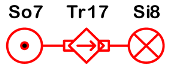
Path 4-1: Export heat through the RHRS
Disclaimer/Publisher’s Note: The statements, opinions and data contained in all publications are solely those of the individual author(s) and contributor(s) and not of MDPI and/or the editor(s). MDPI and/or the editor(s) disclaim responsibility for any injury to people or property resulting from any ideas, methods, instructions or products referred to in the content.

