Article

Build Plate Heating and Cooling Technique Using Peltier Element for Fused Filament Fabrication

1
Department of Electronics Engineering, Myongji University, Yongin 17058, Republic of Korea
2
School of Electrical Engineering, University of Ulsan, Ulsan 44610, Republic of Korea
*
Author to whom correspondence should be addressed.
Electronics 2023, 12(8), 1918; https://doi.org/10.3390/electronics12081918
Submission received: 7 March 2023 / Revised: 6 April 2023 / Accepted: 17 April 2023 / Published: 19 April 2023
(This article belongs to the Section Electronic Materials)

Abstract

:
In fused filament fabrication, the adhesion force between the build plate and the target object must be strong enough during operation. It is, however, an obstacle to detaching the object after printing. The adhesion force heavily depends on the temperature of the build plate. This work suggests controlling the temperature of the build plate using the Peltier module that alters the heat flow direction. The modified build plate replaces the factory-equipped build plate of a commercial fused filament fabrication machine. The experimental results show that the modified build plate leads to 16.6 °C, approximately 9 °C less than the ambient temperature, even with 23.9–27.1% less total energy consumption than the primary build plate.

1. Introduction

A 3D printer manufactures a three-dimensional object through various methods. There are many types of 3D printers. The mainly used techniques are as follows: fused filament fabrication (FFF) or fused deposition modeling (FDM), stereo lithography apparatus (SLA), and selective laser sintering (SLS). FFF is a way to produce the output by extruding a melted plastic filament at a high-temperature nozzle. It stacks the melted filament to build the object layer by layer [1,2]. SLA is a method that solidifies and stacks the layers of the object by firing a laser at a place containing liquid resin [3]. The SLS technique is the process that melts a large amount of small powder such as plastics, metals, or glass with a laser and then solidifies them to stack the object’s layers [4].
Each method has its advantages and disadvantages. SLA can make an output object that has a high-resolution and clean surface finish, but it uses liquid resin as a material that is difficult to handle due to its harmfulness. Furthermore, the price of equipment and materials is relatively high. SLS can use various materials and does not need a supporter while it requires a cooling process to separate the output object from the powder. Furthermore, the attached powder should be removed from the output. SLS also needs a chamber because the powder makes ultrafine particles.
FFF machines are widely used in various industrial fields because their equipment structure and program are simple, the price and maintenance cost are low, and they can be easily enlarged [5,6,7]. Because of these advantages, many industries pay attention to mass production and automation using FFF machines [8]. However, there would be some obstacles to using FFF machines for mass production. The first one is the printing time. A typical FFF machine usually requires a long time to finish its job. For example, the FFF machine used in this study takes approximately 20 min to print a cube with a side of 20 mm, which is a similar size to a dice. However, a slightly larger cube with a side of 40 mm takes approximately 120 min. Operating as many devices as possible at the same time may resolve the problem of a long printing time to proceed with mass production. Another problem is detaching the built object from the FFF machine. The 3D printers, including the FFF machine, must firmly hold the object while printing it. This is because a slight movement or vibration from the object decreases the output quality or even spoils the object [1]. Therefore, fixing the object is essential in 3D printers.
The FFF machine has a build plate to hold the object, and it is important to maintain adhesion between the build plate and the object during printing [9,10]. In some cases, the cost-effective FFF machines require an intervention that an operator pastes paper glue on the build plate before printing [11]. Another FFF machine has a coated build-plate [12]. In general, many cases use a printed circuit board (PCB) pattern or rubber heater beneath the build plate [13,14] because the temperature changes adhesion force between the object and the build plate [15,16]. These types of FFF machines heat up the build plate to maximize the adhesion forces and prevent heat shrinking [10,17]. However, the strong adhesion force disturbs the detachment of the output from the build plate. In order to detach the object, it needs external force, such as twisting the build plate or scraping the adhesive surface of the build plate and the object with a scraper, which is a hurdle for mass production and automation.
A number of studies have focused on the removal of finished parts from the build plate in previous works. M. Glatt et al. [18] proposed combinations of detaching processes using various parameters to be applied in the printed part detaching from the FFF machines. The proposed system has a blade to scrape between the printed part and the build plate to overcome the adhesive force. The proposed system can apply to all FFF machines with a glass build plate. Aroca et al. [19] suggested a general methodology for monitoring the operation of a 3D printer which is able to automatically remove printed parts after printing is completed. They proposed a robot arm to remove printed parts, computer vision systems that observe printing, and the printer control software. P. Becker et al. [20] also used a robot arm, but they suggested an unloading process that automatically removes the printed parts using a robot arm with a gripper finger design. The suggested algorithm calculates the gripping position to remove the printed part without machine vision, but by reading the 3D printer’s head movement data. Polyurethane foam fingers and tong grippers provide the required force to the adaptable surface. In addition, for non-destructive separation, the output was separated by rotation based on three axes. Previous works have focused on a physical mechanism to detach the printed parts from the build plate. However, a method could be to reduce the adhesion forces of the build plate by exploiting the build plate’s characteristic that the adhesion force decreases when the temperature decreases. Therefore, the focus is on cooling down the temperature of the build plate after the printing finishes to lower the adhesion forces to help mass production. A Peltier module is used to drop the build plate temperature under ambient temperature.
The contributions of this paper are as followed:
  • Suggested method uses a Peltier module to heat and cool the building plate instead of the heater.
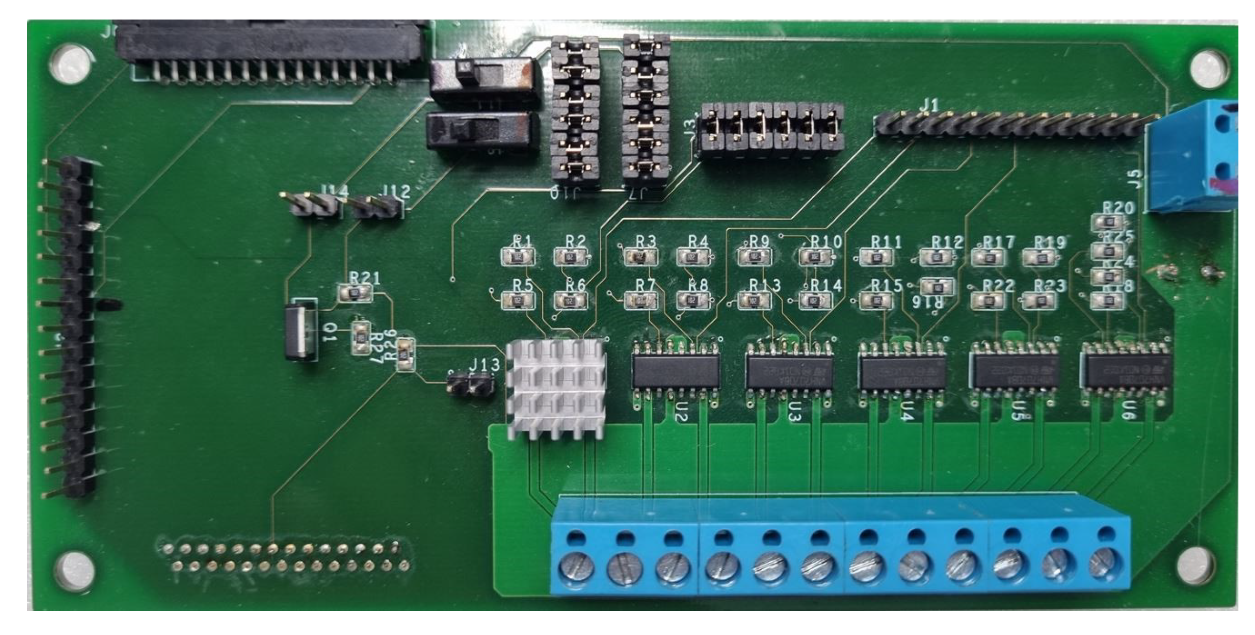
  • The Peltier module controller is designed using a brushed DC motor driver.
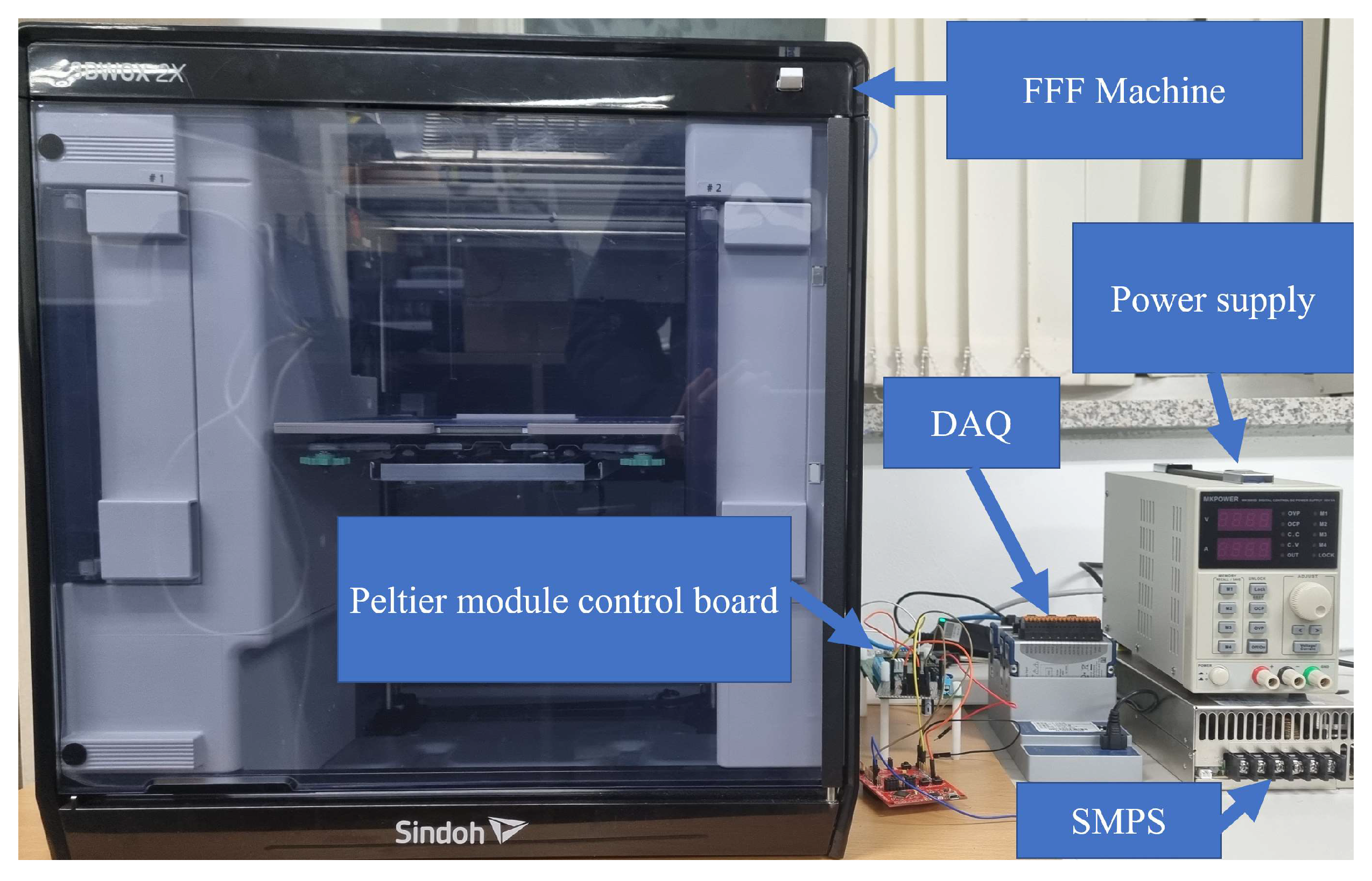
  • A commercial FFF machine is modified and shows how the Peltier module effectively controls the temperature of the build plate.
The proposed method shows that the build plate using the Peltier module cools its temperature down from 25 °C to 16 °C with an energy overhead of less than 10% compared with the total energy consumption of the rubber heater.

2. Fused Filament Fabrication

2.1. Mechanism of Fused Filament Fabrication Machine

FFF is a famous technology of 3D printers for building an object. It melts and stacks the base material to produce output. The widely used base material is a thin and long polylactic acid (PLA) filament. The typical FFF machine includes an actuator, extruder, nozzle, and a build plate, as shown in Figure 1.

2.1.1. Actuator, Nozzle, and Extruder

Actuators move the nozzle and the height of the build plate in general. Alternatively, there are some FFF machines that only move the nozzle while the build plate is fixed [21]. For example, each actuator that uses the stepper motor or linear motor manages to move in each direction as Figure 1 [22]. A nozzle has an embedded heater that continuously melts the filament to liquid when the FFF machine prints an object. Then, an extruder pushes the filament behind the heater to make a filament come out from a nozzle. There are two types of FFF machines according to the filaments feed method. The direct-drive machine moves the extruder with the nozzle. It has the advantage of the extruder accurately controlling the push or pull of the filament [23]. On the other hand, the Bowden machine feeds the filament from the extruder of the filament spool located far from the nozzle [24], as shown in Figure 1. The direct machine’s nozzle mounting extruder has much more mass, which causes much more inertia than the Bowden machine. The suggested technique is implemented to the Bowden machine in this work, but it can also be applied to the direct-drive machine.

2.1.2. Build Plate

The extruded filament from the nozzle begins to form a target object upon the build plate. The filament rapidly cools down to ambient temperature and becomes hardened and fixed in shape. While the melted filament is flowing, the actuator moves the nozzle and the build plate to draw a single layer of the target object. The FFF machine finally adjusts the height of the nozzle to prepare the next layer drawing. It stacks every horizontal layer of the object to complete it. The build plate has an important role: The filament will just flow down if the build plate does not exist, thus it is hard to maintain the target object shape. The build plate must hold the bottom layer to combine the other layers at the exact location. Otherwise, the FFF machine may print the wrong shape even though the nozzle moves slowly.

3. Adhesion Force According to the Temperature

It is important to raise the adhesion force between the lowest layer of the object and the build plate to maintain the shape of the object during printing. There are several ways to raise the adhesion force.
  • Applying adhesive to the build plate [11,25].
  • Increasing adhesion using a cleated surface [12].
  • Heating the build plate to a certain temperature [26].
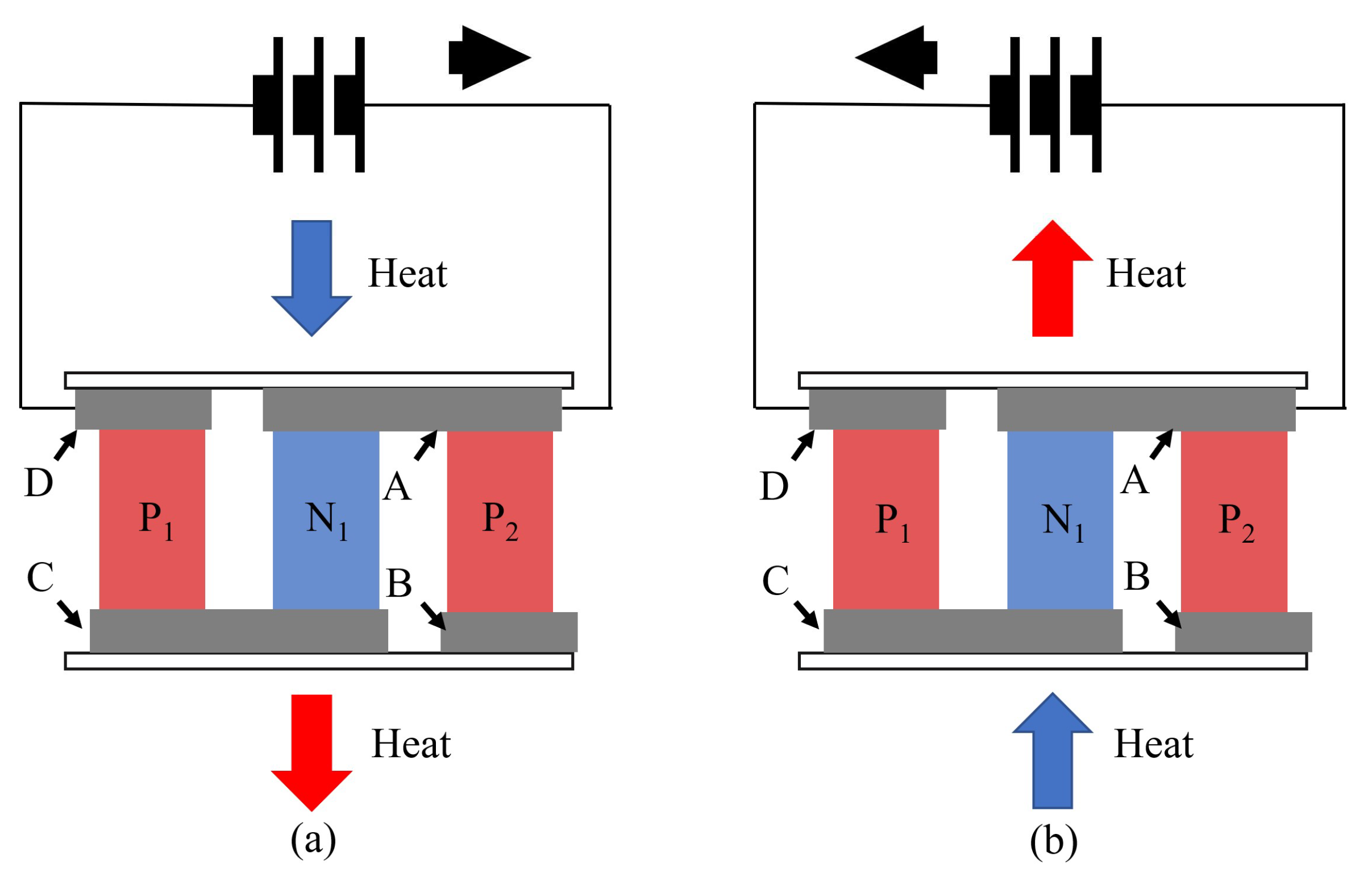
Among those methods, many FFF machines use a heating bed to heat the build plate because it is cheap and does not require an additional step before printing. The adhesion force between the build plate and the object varies according to the build plate temperature. A higher build plate temperature increases the adhesion force and vice versa [15]. Therefore, the FFF machine uses a PCB pattern heater or rubber heater as a heating bed to increase the temperature of the build plate during printing. However, the heating bed is only possible to heat up, so it requires a long time after the printing to lower the adhesion force by cooling down the build plate. In this study, the build plate is improved using a Peltier module to heat up or cool down to achieve the target temperature.

4. Peltier Module

The Peltier module is a device that transfers heat when electricity is applied [27]. Figure 2 shows its structure and operation. The Peltier module has ceramic plates with high thermal conductivity on the top and bottom. There is an array of thermoelectric semiconductor pellets between the plates [28]. The pellets are of p-type and n-type, and they are connected in series with copper tabs. The first and last pallets are connected to the wires for the power supply.
When the electric current flows in a clockwise direction, as shown in Figure 2a, the electrons move from copper plate D to p-type semiconductor P 1 with a potential difference. The electron absorbs heat energy from the ceramic plate upon A and D. In copper plate C, electrons move to the n-type semiconductor N 1 while emitting heat energy. This process cools down a ceramic plate upon A and D while it heats another ceramic plate underneath C and B due to energy absorption and emission.
If the current flows in the counterclockwise direction, electrons move from the p-type semiconductor P 2 to the n-type semiconductor N 1 . This makes the same process described above, but the heat flow direction is altered. As a result, the Peltier module changes the ceramic plate’s hot and cold sides depending on the electric current direction. The proposed build plate using a Peltier module exploits the relationship between the electric current direction and heat transfer direction by replacing a rubber heater underneath the build plate of the FFF machine with the Peltier module array. The rubber heater only makes the build plate hot, but the Peltier module can heat up the build plate like the rubber heater and cools down the build plate to below ambient temperature.

5. Cooling Procedure

The FFF machine needs a cooling procedure that lowers the temperature of the build plate to decrease the adhesive force. The rubber heater does not consume any electricity during the cooling procedure since the rubber heater does not have any cooling functionality. Furthermore, it cannot lower the temperature of the build plate below the ambient temperature. The above procedure is denoted as passive cooling. It is proposed that an additional active cooling procedure uses a Peltier module and a fan after the temperature of the build plates reaches the ambient temperature. The active cooling procedure consumes electric power to lower the temperature below the ambient temperature. The Peltier module transfers heat from the build plate to the ambient and the electric fan attached to the Peltier module cools down the heat sink and the hot side of the Peltier module.

6. Hardware Implementation

Each side of the Peltier module becomes hot and cold depending on the direction of the electric current flow, as noted in Section 4. An H-bridge circuit is used to control the operation of the Peltier module. Thus, it enables one to arbitrarily control the temperature of the build plate. The H-bridge circuit consists of four metal-oxide-semiconductor field-effect transistors (MOSFETs) and alters the electric current flow direction of an electric load. Figure 3 depicts an H-bridge circuit with a Peltier module as an electric load. Two upper MOSFETs ( H 1 and H 2 ) compose high-side switches and two lower MOSFETs ( L 1 and L 2 ) compose low-side switches, respectively. The electric load is located in the middle of high-side switches and low-side switches. The current flows like the blue line when MOSFET H 1 and MOSFET L 2 are turned on. On the contrary, the red line shows the current flow direction when MOSFET H 2 and MOSFET L 1 are turned on. A brushed DC motor driver consists of an H-bridge circuit. Therefore, a brushed DC motor driver is used rather than implementing an H-bridge circuit.
A STMicroelectronics’s brushed DC motor driver VNH7070AS [29] is used to control the Peltier module. The maximum current ratings of VNH7070AS are 30 A at peak and 15 A in continuous operation, which is enough for the KRYOTHERM’s Peltier module TGM-199-1.4-0.8 [30]. Figure 4 shows the Peltier module controller implemented using VNH7070AS.
The proposed build plate has three Peltier modules in the center of the back of the build plate.
There are heat sinks on the opposite sides of each Peltier module attached to the build plate to facilitate the heat exchange of Peltier modules with the air.

7. Experiments

7.1. Experimental Setup

The typical commercial FFF machine equips a build plate with a rubber heater. Sindoh’s 3DWOX 2X [31], a commercial FFF machine, is modified to implement a build plate with a Peltier module. Figure 5 shows a measurement setup. Power consumption and temperature data are collected at every 100 μs by the National Instrument’s Data acquisition system (DAQ) NIc-9148 chassis, NI9223, and NI9205 modules [32,33,34]. The voltage and current applied to the Peltier modules are measured. A 50 mΩ shunt resistor is used to measure the current flow through the Peltier modules because DAQ can only measure the voltage. The original FFF machine uses a SEMITEC’s thermistor, 103NT-4-R025H34G [35], to measure the temperature of the build plate, so the same one is equipped. The original machine is used as a baseline, and it immediately cuts the build plate heating power off after it finishes the printing job. After that, the machine waits until the build plate temperature reaches the ambient temperature, which is denoted as a passive cooling procedure.
The modified machine starts an active cooling procedure after the temperature of the build plate reaches room temperature. Active cooling can cool the build plate down below room temperature. The firmware source code is modified to implement an active cooling procedure.

7.2. Experimental Results

This section compares the time and energy consumption between the baseline and the FFF machine that uses a Peltier module as a build plate heater printing small objects shown in Figure 6 and Figure 7. Both FFF machines warm up the build plate to 60 °C, but a machine with a Peltier module only heats up the center area of the build plate. The Peltier module heats up 12.5% of the build plate while the rubber heater heats up the entire build plate. This technique improves the energy efficiency of the heating process. Note that the machine measures the center area temperature of the build plate.
Table 1 shows the temperature control performance of both machines and the adhesion force for each temperature. The Peltier module increases the temperature of the build plate faster than the rubber heater due to the heat characteristic. Moreover, it decreases the temperature faster than the rubber heater during the passive cooling procedure due to the heat sink. For the baseline, the final temperature of stick printing and circle printing is 25.5 °C and 25.8 °C, respectively. The active cooling procedure cools down the build plate by at most 16.6 °C for both printings. The required force for part removal horizontally with a push–pull gauge connected to the scraper is measured. The presented value is an average of five times for each case. As expected, the adhesion force is stronger at high temperatures. The required force for the removal of both parts is 5.7 kgf and 10.89 kgf at 60 °C, respectively. At the lowest temperature, 16.6 °C, these are 2.18 kgf and 7.21 kgf, respectively. The adhesion force of the circle part is stronger than the stick part because of the difference in shape. However, there is a tendency for the adhesion force to decrease as the build plate temperature decreases. Figure 8 and Figure 9 show printed parts on the build plate using the Peltier module. During experiments, no warping effect is found in the printed parts on the build plate using the Peltier module. This is because the proposed build plate is heated up to 60 °C, such as with the rubber heater, which makes enough adhesion force.
Figure 10 and Figure 11 compare the temperature and power consumption changes during the printing. Note that the temperature and power graph of a machine with a Peltier module starts later because the graphs are aligned at the beginning of printing. The rubber heater takes approximately 4 min and consumes more power than the Peltier module during the heating phase. The Peltier module increases the build plate temperature by approximately 1 min at the cost of fluctuations in temperature and power consumption. However, this fluctuation does not cause a problem because the machine does not start printing. In the printing phase, both heaters keep the target temperature well and take the same time to print the target model. The Peltier module consumes less power than the rubber heater because it heats the part of the build plate up. There is no power consumption within the passive cooling phase for both machines. It is confirmed that the heat sink in the Peltier module helps cool down the build plate without any cost. When the temperature of the build plate reaches room temperature, the baseline finishes the cooling procedure. However, the Peltier module starts an additional active cooling phase. The power consumption rapidly increases to transfer heat from the build plate to the heat sink and to run the cooling fan.
The average power and energy consumption of both heaters are summarized in Table 2. The Peltier module consumes less energy in the warming-up phase because it only heats up 12.5% of the build plate. It incurs less power consumption and a faster warming-up time. Both machines show similar power and energy consumption in the printing phase and the passive cooling phase. In the active cooling phase, the Peltier module consumes approximately 60 W, but the energy consumption is not due to the short time. Note that it consumes more power than in the warming-up to run the electric fan. The energy consumption overhead caused by the active cooling phase is 13.7% and 5.8% for the stick printing and circle printing, respectively. However, the Peltier module consumes 27.1% and 23.9% less energy than the baseline in total.

8. Conclusions

This paper proposes a method for overcoming the limitations of the temperature control of existing rubber heaters to use an FFF machine for mass production. First of all, the build plate of the FFF machine was modified to use a Peltier module to adjust the temperature by controlling the direction of the current flow. The temperature of the surface of the Peltier module and the build plate was adjusted using a DC motor driver. The DC motor driver controlled the direction of the current flow. Second, it presented the comparison of the temperature control capabilities of a build plate using a Peltier module with a build plate using a rubber heater for two models. It was confirmed that the device lowers the temperature of the build plate using a Peltier module which is at most 8 °C lower than room temperature, and also measured the power consumption of both heaters. As a result, the proposed method cools the build plate down to 8 °C lower than room temperature using the Peltier module with an energy overhead of approximately 10% compared with the rubber heater. The adhesion force was lowered between the surface of the build plate and the last layer of the output. The proposed method helps in mass production and automation using 3D printers.

Author Contributions

S.H.: investigation, design, assembly, software, validation, J.P.: conceptualization, writing, supervision, funding acquisition, J.K.: conceptualization, writing, supervision, funding acquisition, validation. All authors have read and agreed to the published version of the manuscript.

Funding

This work was supported by the National Research Foundation of Korea under grants funded by the MSIT (NRF-2021R1F1A1060208 and NRF-2019R1F1A1060525).

Data Availability Statement

Data sharing is not applicable to this article.

Conflicts of Interest

The authors declare no conflict of interest.

References

  1. Carneiro, O.S.; Silva, A.; Gomes, R. Fused deposition modeling with polypropylene. Mater. Des. 2015, 83, 768–776. [Google Scholar] [CrossRef]
  2. Edgar, J.; Tint, S. Additive manufacturing technologies: 3D printing, rapid prototyping, and direct digital manufacturing. Johns. Matthey Technol. Rev. 2015, 59, 193–198. [Google Scholar] [CrossRef]
  3. Quan, H.; Zhang, T.; Xu, H.; Luo, S.; Nie, J.; Zhu, X. Photo-curing 3D printing technique and its challenges. Bioact. Mater. 2020, 5, 110–115. [Google Scholar] [CrossRef] [PubMed]
  4. Prakash, K.S.; Nancharaih, T.; Rao, V.S. Additive manufacturing techniques in manufacturing—An overview. Mater. Today Proc. 2018, 5, 3873–3882. [Google Scholar] [CrossRef]
  5. Okwuosa, T.C.; Stefaniak, D.; Arafat, B.; Isreb, A.; Wan, K.W.; Alhnan, M.A. A lower temperature FDM 3D printing for the manufacture of patient-specific immediate release tablets. Pharm. Res. 2016, 33, 2704–2712. [Google Scholar] [CrossRef] [PubMed]
  6. Huang, Y.; Leu, M.C.; Mazumder, J.; Donmez, A. Additive manufacturing: Current state, future potential, gaps and needs, and recommendations. J. Manuf. Sci. Eng. 2015, 137, 014001. [Google Scholar] [CrossRef]
  7. Thumsorn, S.; Prasong, W.; Kurose, T.; Ishigami, A.; Kobayashi, Y.; Ito, H. Rheological behavior and dynamic mechanical properties for interpretation of layer adhesion in FDM 3D printing. Polymers 2022, 14, 2721. [Google Scholar] [CrossRef] [PubMed]
  8. Available online: https://www.reportsanddata.com/press-release/global-additive-manufacturing-market (accessed on 1 March 2023).
  9. Płaczek, D. Adhesion between the bed and component manufactured in FDM technology using selected types of intermediary materials. In Proceedings of the MATEC Web of Conferences, Sibiu, Romania, 5–7 June 2019; Volume 290, p. 01012. [Google Scholar]
  10. Spoerk, M.; Gonzalez-Gutierrez, J.; Lichal, C.; Cajner, H.; Berger, G.R.; Schuschnigg, S.; Cardon, L.; Holzer, C. Optimisation of the adhesion of polypropylene-based materials during extrusion-based additive manufacturing. Polymers 2018, 10, 490. [Google Scholar] [CrossRef] [PubMed]
  11. Mwema, F.M.; Akinlabi, E.T.; Mwema, F.M.; Akinlabi, E.T. Basics of fused deposition modelling (FDM). Fused Depos. Model. Strateg. Qual. Enhanc. 2020, 30, 1–15. [Google Scholar]
  12. Shafer, C.S.; Siddel, D.H.; Elliott, A.M. Cleated print surface for fused deposition modeling. J. Mech. Eng. Autom. 2017, 7, 1359–1365. [Google Scholar]
  13. Triyono, J.; Pratama, A.; Sukanto, H.; Nugroho, Y.; Wijayanta, A.T. Effect of heat bed temperature of 3D bioprinter to hardness and compressive strength of scaffold bovine hydroxyapatite. In Proceedings of the AIP Conference Proceedings, Maharashtra, India, 28 September 2018; IOP Publishing: Bristol, UK, 2018; Volume 1931, p. 030059. [Google Scholar]
  14. Amridesvar, S.; Balakrishnan, S.; Akash, S.; Muthu, G.; Vignesh, K. Modeling phase distribution in build platform for better printing in FDM machine. In Proceedings of the IOP Conference Series: Materials Science and Engineering, Chennai, India, 16–17 September 2020; IOP Publishing: Bristol, UK, 2020; Volume 988, p. 012047. [Google Scholar]
  15. Spoerk, M.; Gonzalez-Gutierrez, J.; Sapkota, J.; Schuschnigg, S.; Holzer, C. Effect of the printing bed temperature on the adhesion of parts produced by fused filament fabrication. Plast. Rubber Compos. 2018, 47, 17–24. [Google Scholar] [CrossRef]
  16. Snapp, K.L.; Gongora, A.E.; Brown, K.A. Increasing throughput in fused deposition modeling by modulating bed temperature. J. Manuf. Sci. Eng. 2021, 143, 094502. [Google Scholar] [CrossRef]
  17. Bahnini, I.; Uz Zaman, U.K.; Rivette, M.; Bonnet, N.; Siadat, A. Computer-aided design (CAD) compensation through modeling of shrinkage in additively manufactured parts. Int. J. Adv. Manuf. Technol. 2020, 106, 3999–4009. [Google Scholar] [CrossRef]
  18. Glatt, M.; Greco, S.; Yi, L.; Kirsch, B.; Aurich, J.C. Development and implementation of a system for the automated removal of parts produced by Fused Deposition Modeling. Procedia CIRP 2021, 103, 109–114. [Google Scholar] [CrossRef]
  19. Aroca, R.V.; Ventura, C.E.; De Mello, I.; Pazelli, T.F. Sequential additive manufacturing: Automatic manipulation of 3D printed parts. Rapid Prototyp. J. 2017, 23, 653–659. [Google Scholar] [CrossRef]
  20. Becker, P.; Henger, E.; Roennau, A.; Dillmann, R. Flexible object handling in additive manufacturing with service robotics. In Proceedings of the 2019 IEEE 6th International Conference on Industrial Engineering and Applications (ICIEA), Tokyo, Japan, 12–15 April 2019; pp. 121–128. [Google Scholar]
  21. Ratiu, M.; Anton, D.; Negrau, D. Experimental study on the settings of Delta and Cartesian 3D printers for samples printing. In Proceedings of the IOP Conference Series: Materials Science and Engineering, Sanya, China, 12–14 November 2021; IOP Publishing: Bristol, UK, 2021; Volume 1169, p. 012026. [Google Scholar]
  22. Li, B.; Liu, J.; Gu, H.; Jiang, J.; Zhang, J.; Yang, J. Structural Design of FDM 3D Printer for Low-melting Alloy. In Proceedings of the IOP Conference Series: Materials Science and Engineering, Kazimierz Dolny, Poland, 21–23 November 2019; IOP Publishing: Bristol, UK, 2019; Volume 592, p. 012141. [Google Scholar]
  23. Liu, H.; Liu, Z.; Hao, S. Design of a Throat-extended FDM Extruder for Multi-axis 3D Printing. Stroj. Vestn./J. Mech. Eng. 2021, 67, 180–190. [Google Scholar] [CrossRef]
  24. Hoque, M.; Kabir, H.; Jony, M. Design and construction of a bowden extruder for a FDM 3D Printer Uses 1.75 Mm filament. Int. J. Tech. Res. Sci 2018, 3, 282–288. [Google Scholar] [CrossRef]
  25. Sanatgar, R.H.; Campagne, C.; Nierstrasz, V. Investigation of the adhesion properties of direct 3D printing of polymers and nanocomposites on textiles: Effect of FDM printing process parameters. Appl. Surf. Sci. 2017, 403, 551–563. [Google Scholar] [CrossRef]
  26. Oo, H.L.; Ye, K.Z.; Linn, Y.H. Modeling and controlling of temperature in 3D printer (FDM). In Proceedings of the 2018 IEEE Conference of Russian Young Researchers in Electrical and Electronic Engineering (EIConRus), Moscow and St. Petersburg, Russia, 29 January–1 February 2018; pp. 1738–1742. [Google Scholar]
  27. Min, G.; Rowe, D. Improved model for calculating the coefficient of performance of a Peltier module. Energy Convers. Manag. 2000, 41, 163–171. [Google Scholar] [CrossRef]
  28. Kudva, N.; Veeresha, R. A review on thermoelectric (peltier) module. Int. J. Progress. Res. Sci. Eng. 2020, 1, 212–216. [Google Scholar]
  29. Available online: https://www.st.com/resource/en/datasheet/vnh7070as.pdf (accessed on 1 March 2023).
  30. Available online: https://kryothermtec.com/assets/dir2attz/ru/TGM-199-1.4-0.8.pdf (accessed on 1 March 2023).
  31. Available online: https://www.sindoh.com/ko/ (accessed on 1 March 2023).
  32. Available online: https://www.ni.com/docs/en-US/bundle/ni-9148-seri/resource/375519c.pdf (accessed on 1 March 2023).
  33. Available online: https://www.ni.com/docs/en-US/bundle/ni-9205-specs/page/specifications.html (accessed on 1 March 2023).
  34. Available online: https://www.ni.com/docs/ko-KR/bundle/ni-9223-specs/page/specs.html (accessed on 1 March 2023).
  35. Available online: http://www.semiteckorea (accessed on 1 March 2023).
Figure 1. Typical structure of the Bowden FFF machine.
Electronics 12 01918 g001
Figure 2. Principle of the Peltier module. Depending on the current flow, the heating side is different. (a) The current flow in the clockwise direction; and (b) The current flow in the counterclockwise direction.
Electronics 12 01918 g002
Figure 3. Circuit of H-bridge with Peltier module.
Electronics 12 01918 g003
Figure 4. Peltier module controller.
Electronics 12 01918 g004
Figure 5. Experimental setup.
Electronics 12 01918 g005
Figure 6. Target model (stick).
Electronics 12 01918 g006
Figure 7. Target model (circle).
Electronics 12 01918 g007
Figure 8. The printed target model (stick) on the build plate using the Peltier module.
Electronics 12 01918 g008
Figure 9. The printed target model (circle) on the build plate using the Peltier module.
Electronics 12 01918 g009
Figure 10. Power consumption and build plate temperature using the Peltier module and the rubber heater for the stick model.
Electronics 12 01918 g010
Figure 11. Power consumption and build plate temperature using the Peltier module and using the rubber heater for circle model.
Electronics 12 01918 g011
Table 1. Comparison between the warming-up time, printing time, passive cooling time, active cooling time, printing temperature, finished temperature, and required force for part removal after cooling process using rubber heater and Peltier module heater for each target model.
StickCircle
RubberPeltierRubberPeltier
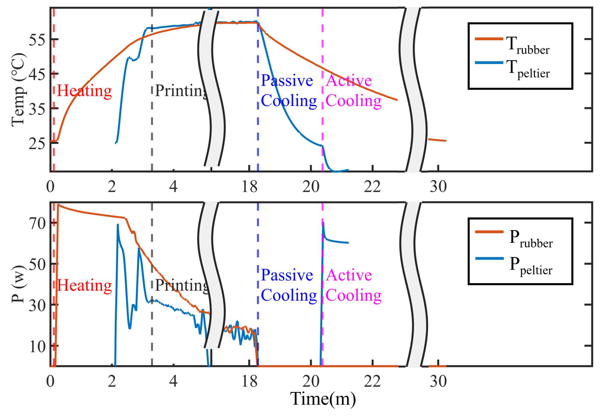
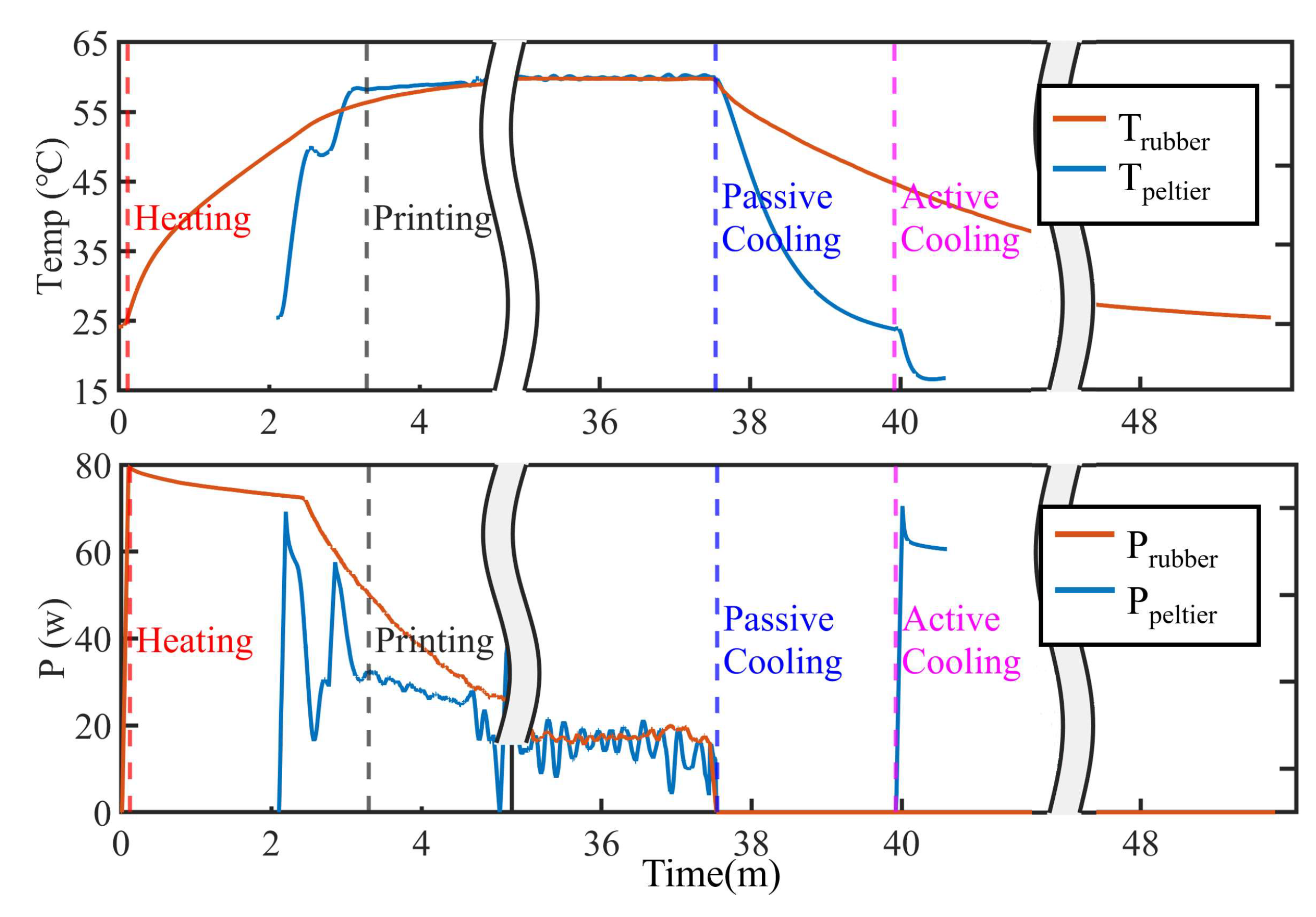
Elapsed time in each process (s)
Warming-up2106221061
Printing8562010
Passive cooling720180725137
Active cooling-56-36
Achieved temperature (°C)
Printing60.060.0
Finished25.516.625.816.6
Required force for part removal (kgf)
60.0 (°C )5.710.89
25.5 (°C )2.48.37
16.6 (°C )2.187.21
Table 2. Comparison of the power consumption and energy consumption of the rubber heater and Peltier module heater for each target model.
StickCircle
RubberPeltierRubberPeltier
Average power consumption for each phase (W)
Warming-up62.2540.8065.1940.31
Printing18.7918.5617.5216.42
Passive cooling----
Active cooling-61.27-61.65
Energy consumption for each phase (Wh)
Warming-up4.150.704.350.69
Printing4.474.669.799.42
Passive cooling----
Active cooling-0.86-0.62
Total energy consumption (Wh)
Energy8.626.2814.1410.76
Disclaimer/Publisher’s Note: The statements, opinions and data contained in all publications are solely those of the individual author(s) and contributor(s) and not of MDPI and/or the editor(s). MDPI and/or the editor(s) disclaim responsibility for any injury to people or property resulting from any ideas, methods, instructions or products referred to in the content.

