Abstract
A system-level total ionizing dose test method of satellite subsystems is discussed in the context of the radiation qualification of a satellite. System-level tests are performed with high-energy X-rays, and the irradiation results of the key subsystems, including the on-board computer, attitude- and orbit-control-system computer, and battery management system, are presented and analyzed in terms of the repeatability of the results, the observability issues, and the importance of the test conditions. Furthermore, the main benefits of the system-level total ionizing dose tests of the given subsystems are discussed, as well as the risks related to performing tests at the system level.
1. Introduction
The radiation qualification of electronic components is an important part of the flight qualification of satellites. Depending on the target orbit, mission lifetime, and solar activity, the specific radiation tolerance/hardness level needs to be assured []. To meet this goal, the radiation testing of electronics is performed either by the manufacturer of the rad-tolerant or rad-hard parts or by the satellite developer if COTS (commercial off-the-shelf) components are chosen for the design. The standard approach involves tests at the level of the basic components, following well-established test specifications [,,]. However, owing to the rapid increase in the use of COTS components, the increase in the complexity of electronic flight systems, and the search for cost reduction in the NewSpace era, new alternative test methods are being sought, including alternative radiation sources [,] and tests at the level of the electronic system (which may mean the electronic board, satellite module, or even the whole satellite []; processor or SoC devices are understood in this paper to be components, contrary to what was proposed, e.g., in []).
System-level tests of electronics were extensively studied within the RADSAGA project, providing insights into the use of this method for high-risk acceptance missions in mild radiative environments, incorporating COTS components []. Furthermore, a methodology for using deeply penetrating beams (protons, neutrons, and mixed fields) for systems’ qualification was provided in []. An example of such system-level tests with the mixed field at the CHARM [] facility is the radiation characterization of the payload and the main data-handling unit of the CELESTA CubeSat [,] or the Ninano CubeSat computer accompanied by the 3D-Plus CMOS camera module []. In another example, the board-level proton tests of the ESP603 single-board space computer, evaluating its SEE (single event effects) performance, are presented []. Research on the system-level testing started within the RADSAGA project is continued in the frame of the RADNEXT project [].
The total ionizing dose (TID)-related test at the board/system-level is presented, e.g., in [], where COTS single-board computers (SBCs) are irradiated. In the experiment involving testing in different bias configurations, the failure mechanisms are disclosed, and the degradation of various electrical and functional parameters is given. Another work [] presents irradiations of two different models of the Raspberry Pi SBC: Raspberry Pi Zero and Raspberry Pi 3B+, with the goal of providing basic information on the radiation sensitivity of these devices. Regarding the TID tests performed in that study, the main parameters monitored (and used to assess the health of the SBC) are the operating current (in different modes), the duration of the file transfer over WiFi, and the possibility to perform a command, e.g., play a transferred video file.
In [], system-level radiation testing is discussed based on the results of system-in-package module irradiations. The system-level approach is evaluated for the purpose of electronic system qualification, and various opportunities as well as limitations of this approach are presented.
This paper presents the TID system-level test results of microsatellite subsystems and discusses the role of such tests in the qualification process. The main topics covered include the benefits that such tests bring to satellite developers, the parameter observability issues, the repeatability of results, the small-sample-size implications, as well as the importance of the test conditions. Therefore, certain ideas and issues discussed in [] are reviewed but now in the context of microsatellite subsystem testing and not system-in-package module testing. The novel contribution of the paper is the in-depth analysis of the system-level TID-testing approach for microsatellite subsystems, based on the test results for three various subsystems.
2. Methodology
In this work, we study the role of the system-level TID testing of satellite subsystems in the process of the radiation qualification of the whole satellite. The research is based on a case study of TID tests of complex microsatellite subsystems, including the on-board computers (OBCs), attitude- and orbit-control-system computers (AOCS), and battery management system boards (BMS). The subsystems were developed in the frame of the EagleEye microsatellite project by Creotech Instruments SA and are based on the HyperSat platform. The EagleEye project aims to develop an Earth observation satellite, raise the technology readiness level (TRL) of the microsatellite platform on TRL9, and refine a number of subsystems designed for microsatellites. The satellite will be placed in a low Earth orbit (LEO) early next year and will provide 1 m resolution (ground sampling distance) imagery of Earth.
Two samples of each subsystem type were irradiated to determine whether the results were repeatable. The primary goal of the system-level irradiations was to ensure that subsystems may withstand TID levels exceeding the one expected in the target radiation environment. The secondary goal was that if the subsystem fails, the test should help in understanding what in the system is failing, what the significance of this is, and whether the failing components may be easily replaced.
The OBC and AOCS subsystems of the EagleEye satellite consist of single-board computers utilizing either a processor + FPGA tandem (OBC) or a processor only (AOCS), both incorporating dedicated internal power sections. The BMS features a complex analog section for power control and a mixed analog–digital section for internal telemetry and command handling. All subsystems rely on COTS components meticulously selected for the EagleEye mission. Specifically, a comprehensive radiation data review guided the selection of components resilient to radiation effects. Moreover, some of the crucial components underwent component-level testing before system-level tests, particularly in cases where radiation data were unavailable (e.g., the SDRAM memory). The radiation level of the target mission was simulated using the Omere 5.3 software [], estimating a dose of 5 krad (50 Gy) over the 3-year mission duration (6 months in LEO and 30 months in very low Earth orbit (VLEO)).
The irradiations were performed with high-energy X-rays at the NCBJ (National Centre for Nuclear Research). The 6 MeV linear electron accelerator was used to produce the X-rays: electrons irradiated the tungsten target, and (through the Bremsstrahlung effect) the secondary photon beam with a wide energy spectrum ranging up to 6 MeV was created. The FLUKA [,] Monte-Carlo simulation of the energy spectrum is presented in Figure 1. A similar facility used for TID irradiations, ORIATRON, was described in [,], and the results of both the irradiations and simulations were consistent with those obtained using the standard Co-60 source.
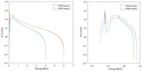
Figure 1.
The Monte-Carlo simulated spectrum of photons emitted from the 1 mm thick tungsten plate irradiated by the 4 MeV and 6 MeV electrons. The same data are plotted twice: using a linear–logarithmic scale (left plot) and a logarithmic–logarithmic scale (right plot).
The dosimetry system relied on the PTW TM30013 ionization chamber, managed by the PTW T10004 electrometer. Throughout irradiation sessions, the ionization chamber was positioned in close proximity to the device under test (DUT), maintaining an identical distance from the radiation source as the DUT itself (refer to Figure 2b below), while the electrometer remained stationed in the control room.
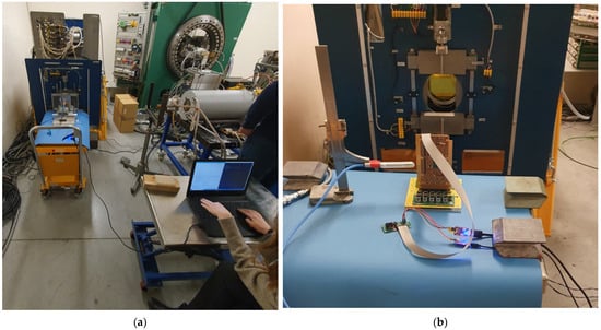
Figure 2.
Test setup during irradiations and functional/electrical tests of the OBC: (a) depicts a segment of the test facility, featuring the accelerator situated on the left, with the OBC positioned on a nearby table. An operator seated at another table conducts functional tests after irradiation step. (b) illustrates the OBC placed in proximity to the accelerator window and the ionization chamber utilized for dosimetry. Communication cables are connected to the OBC for conducting functional tests.
The subsystems underwent individual testing, with only one subsystem sample irradiated at a time. The irradiation sequence, inspired by [], encompassed these key steps:
- Pre-irradiation functional and electrical tests of the subsystem;
- A series of irradiation steps (2.5 krad per step), followed by subsequent functional and electrical tests;
- Post-irradiation functional and electrical tests conducted after reaching 20 krad;
- Room-temperature annealing for a minimum of 24 h, followed by functional and electrical tests;
- High-temperature annealing for 168 h, followed by functional and electrical tests.
Throughout the irradiations, the subsystems were biased with nominal voltage values, while the dose rate maintained a consistent 5 krad/h. The maximum 20 krad total dose reached during the irradiations significantly surpassed the mission’s target dose of 5 krad. The purpose of this overtest approach is to irradiate with a significant TID margin and increase the credibility of results, reducing the risk related to irradiating a relatively low sample size (two subsystem samples for each type). However, it is important to note that despite testing to a higher TID level, inherent part-to-part variations in the radiation response of components persist as a potential risk, which is further addressed in the discussion section of this paper.
The functional and electrical parameters of the subsystems, verified after each irradiation step, were meticulously selected to offer insight into the performance of numerous subsystem components. This selection prioritized the components identified as the most susceptible to radiation (based on pre-test analysis) or those lacking available radiation susceptibility data. The monitored parameters included power supply currents, internal voltage telemetry (compared with digital meter readings), memory operations, and battery charging/discharging, among others.
Regarding the high-temperature annealing process, it was executed at 80 °C, instead of the recommended 100 °C (as suggested in [,]), aligning with the maximum temperature ratings for the components used in the tested subsystems.
Illustrations depicting the example setup for the OBC tests are presented in Figure 2.
3. Results
The key results of the OBC irradiation are depicted in Figure 3 and Figure 4. The abscissa marks the irradiation steps, followed by the annealing steps (room-temperature and high-temperature annealing). Above the abscissa, major events occurring during the irradiation are highlighted, denoted by color-labeled criticality (the darker—the more critical) and the respective event durations.
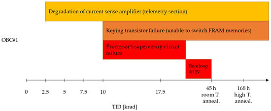
Figure 3.
Graphical representation of the main events observed during OBC#1 irradiation and their duration.
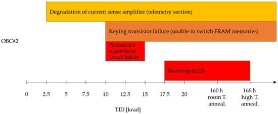
Figure 4.
Graphical representation of the main events observed during OBC#2 irradiation and their duration.
During the initial steps, setup errors and delays led to an accelerated irradiation process for OBC#1 after reaching 10 krad (i.e., steps 12.5 krad and 15 krad were bypassed), halting at 17.5 krad. The room-temperature annealing durations exceeded the planned 24 h for both OBCs, allowing subsystem recovery following high dose-rate irradiation. As per [], parts that fail during irradiation but recover during room-temperature annealing may be considered acceptable for the irradiated TID level, if the dose rate in the target environment is lower than the resultant aggregate of the irradiation and annealing times.
Most of the OBC functions that could be verified during irradiation were operating correctly. However, four errors were observed across different components or sections of the OBC. Three errors—degradation of the current sense amplifier, keying transistor failure, and failure of the processor’s supervisory circuit—resulted from single component failures. These components were subsequently replaced with more radiation-tolerant alternatives in the final design. The origin of the fourth error, a boot loop in the 12 V bank, could not be precisely determined. In both OBCs, it started after the 17.5 krad step, but in OBC#1, the error was observed when the device was already transported from the irradiation facility to Creotech Instruments premises for annealing. The error disappeared in OBC#1 after room-temperature annealing, whereas in OBC#2, it disappeared after 1 h of the high-temperature annealing.
The malfunctioning processor’s supervisory circuit, which impeded the processor’s power-up, was removed after irradiation (OBC#1) or after the 15 krad step (OBC#2). Post-circuit removal, the correct functionality of the processor was verified.
The significant findings concerning the BMS boards are detailed in Figure 5 and Figure 6. While most of the BMS functionality remains intact throughout the entire irradiation, several errors manifest in both devices under test. An error in battery voltage measurement is noted from the 5 krad step, initially around 1% deviation, escalating to approximately 10% during irradiation. This error exhibits partial annealing at higher temperatures. Concurrently, errors in the BMS output voltage and current measurement arise from the 17.5 krad step and vanish post-annealing. The sole major failure, the battery charger malfunction, emerges at the 20 krad step. BMS#2 successfully recovers from this error following annealing, while BMS#1 remains affected.
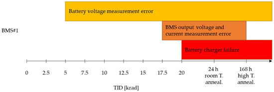
Figure 5.
Graphical representation of the main events observed during BMS#1 irradiation and their duration.
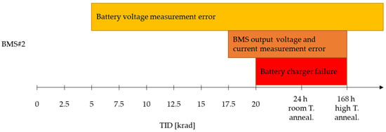
Figure 6.
Graphical representation of the main events observed during BMS#2 irradiation and their duration.
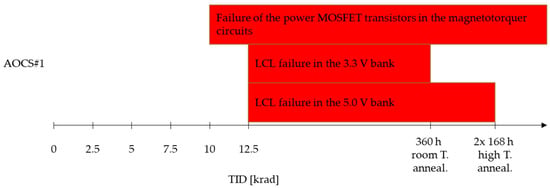
Figure 7.
Graphical representation of the main events observed during AOCS#1 irradiation and their duration (the double high-temperature annealing for AOCS#1 was due to procedure error—during the first annealing step, the AOCS was not biased).
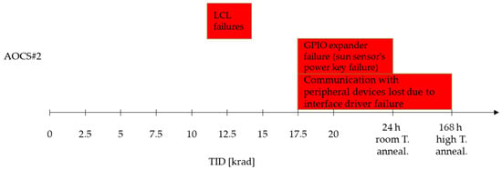
Figure 8.
Graphical representation of the main events observed during AOCS#2 irradiation and their duration.
AOCS#1 underwent irradiation up to 12.5 krad, where critical errors in the LCL (latch-up current limiters) resulted in the failure to power two banks—3.3 V and 5 V. One of the LCL chips recovered after room-temperature annealing and another after high-temperature annealing. In the case of AOCS#2 testing, a different lot’s LCL was employed; yet, it also failed just before reaching 12.5 krad. Consequently, the LCL on the AOCS#2 board was bypassed to continue testing of the subsystem.
At 10 krad, the power MOSFET transistors within the magnetotorquer circuits of AOCS#1 experienced failure. These transistors were subsequently replaced with different parts (new part reference), exhibiting proper functionality throughout the entirety of AOCS#2 testing.
AOCS#2 encountered two critical chip failures at the 17.5 krad dose: the GPIO (general-purpose input/output) expander failure and the serial interface driver failure. The former error recovered post-room-temperature annealing, while the latter error resolved after high-temperature annealing.
4. Discussion
System-level TID radiation tests of the EagleEye microsatellite key subsystems were performed to ensure that the devices may withstand the targeted environmental doses. Most of the major failures were observed at the dose level of 17.5 krad and higher, and a few components failing below 15 krad were replaced in the final design with more radiation-tolerant parts, identified through supplementary component-level radiation tests. Therefore, there shall be at least a threefold margin between the expected dose level in orbit and the level of failures observed during the tests. The second goal of the system-level tests was to determine which components should be replaced, given any failures observed. In most of the cases, this goal was also met: the failing components were detected and replaced with the ones that had better radiation data from the component-level tests. Notably, in the AOCS subsystem, transistors showing failure were replaced before the AOCS#2 irradiation; so, the second test campaign could confirm that the new transistors (already tested at component-level, while waiting for the AOCS#2 irradiation) perform correctly in the subsystem up to the dose of 20 krad. However, there was one instance where the specific component responsible for the subsystem failure at ~17.5 krad—manifesting as a boot loop error in both OBCs—could not be identified.
To evaluate the component radiation performance effectively, good observability of its parameters, both electrical and functional, is required. Achieving this level of observability is relatively straightforward in component-level tests. However, during system-level tests, observability is often more constrained []. An example illustrating this limitation is the challenge encountered in analyzing the boot loop error in OBCs. Despite this, our experiments allowed us to identify failures in several components relatively easily. Most of these components formed a tree-like structure (e.g., processor—interface driver—peripheral devices or processor—FPGA—switching transistor—peripheral device; the failing parts were underlined). This structural hierarchy simplified the search for the failing part: the malfunctioning branch indicated the location of the failure. On the other hand, components building the 12 V power section in the OBC (which entered a boot loop at 17.5 krad) are organized in a feedback loop structure, complicating the search for the failing component. Implementing an approach that emphasizes enhanced observability in such loop structures might streamline the search for the failing component.
Yet another issue is related to the observability in system-level testing: usually, we do not have information about the degradation of the component, but what we see is the failure threshold. In many cases, gathering more extensive information might not be feasible—additional instrumentation could, e.g., decrease the performance. However, more often, this limitation stems from optimizing the test setup for simplicity, cost reduction, and obtaining the most pertinent results for subsystem qualification purposes. For more information on the component degradation, complementary component-level testing would be necessary. This additional information might be crucial at times to precisely determine the failure dose threshold of the entire system, in particular, if there is a limited number of system samples tested (resulting in significant statistical errors), and if the system failure is a result of a failure of a single component.
In our tests, we exposed two samples of each subsystem to radiation to ascertain the repeatability and bolster the credibility of the proposed TID failure threshold. Table 1 summarizes the major failures observed across all the tested subsystems, comparing the results for the two tested samples. The different colors group the results with the same specificity, as discussed below.

Table 1.
Summary of major failures observed during tests, with a comparison of the results for the two samples tested. The different colors group the results with the same specificity, as discussed in the text below.
The results marked in grey indicate good repeatability between samples 1 and 2 of the subsystems; however, the TID failure threshold is insufficiently low, and the parts were replaced in the final design by component-level tested ones, demonstrating higher radiation tolerance. Conversely, light green highlights results demonstrating full repeatability and a sufficiently high TID level (17.5 krad) to accept the part for the mission. Finally, dark green denotes a part replaced after the first test campaign; the replacement was tested at the component level, and its radiation tolerance was confirmed at the system level (it did not fail up to 20 krad).
The results highlighted in blue indicate instances of greater discrepancy, such as a slightly different TID failure threshold or different behavior during the annealing, but the TID failure threshold is also high, and the parts might be accepted.
The yellow color marks the results where no repeatability was observed, but it was due to the fact that the irradiation stopped too early during the first test campaign, to observe failures in given components. During the second test campaign, the TID failure threshold reached a high level (17.5 krad), suggesting potential acceptance of these parts. However, it is important to note that the value of these test results is somewhat lower than, for instance, the blue ones, as there is limited information about the variability of the TID failure level for these parts. The risk related to using these parts could be further reduced by performing complementary tests at the component level.
Finally, the orange color represents the results for LCLs in both AOCS boards. The same type of LCL (same manufacturer and reference number) functioned correctly up to 20 krad in the OBCs. For the AOCS design, a new lot was chosen, which has shown better electrical performance—but it failed at 12.5 krad in AOCS#1. Subsequently, a third lot also failed at 12.5 krad during the AOCS#2 test campaign. This TID level of failures gives too little margin for the target mission, and a replacement for the component was searched for. The procurement of LCL components occurred during a global shortage of electronic components due to the pandemic, potentially contributing to significant variations between different lots. These variations might indicate variations in the manufacturing process, semiconductor fabrication plant, or even semiconductor layout, impacting the parameters of the new lots. This situation underscores the importance of testing the exact component lot planned for use in the flight model of the system. The change in electrical performance of the new lot might serve as an indicator that different radiation performance could be expected. However, no change in electrical performance does not mean that no change in the radiation response of the new lot is guaranteed [].
In our test campaigns, we did not encounter any critical discrepancies between the results obtained from both samples of the same subsystem (e.g., sample#1 being fully tolerant up to 20 krad and sample#2 with the same components failing at 5 krad). However, the most unexpected outcome arose in the case of the LCLs. These components were fully tolerant up to 20 krad in the OBCs; yet, two different lots of these components failed at 12.5 krad in the AOCS boards.
With a limited number of samples, our ability to predict potential failures in the target system due to potential pathologies within components’ distributions, even within the same lot, is restricted []. When dealing with a sample size of only two, we have a minimum of repeatability, which brings more credibility to the results but is far too low to state that we have no problems with thick-tailed or bipolar distributions. While the overtest approach and the application of a substantial margin (such as our threefold margin between the expected orbital dose and the weakest components’ threshold dose) is useful for the normal/lognormal distributions of components’ radiation response, it may not effectively address issues arising from pathological distributions []. Radiation qualification of the subsystems based on the system-level tests of two samples only, requires accepting the risk described above. To address this challenge, the MINIATURA-7, funded by the National Science Centre (NCN, Narodowe Centrum Nauki) and recently initiated at the NCBJ, aims to investigate the radiation response and failure distributions in large sample sizes of single board computers under TID irradiation. This endeavor holds promise for shedding new light on the discussed problem.
In component-level test specifications like [], the worst case bias configuration is required for the components under irradiation, to produce the maximum degradation. In the EagleEye tests, all subsystems were biased during irradiation, aligning with the “test as you fly” approach and owing to the limited number of samples available for testing. However, we tried to set various bias or operating conditions of basic components wherever feasible. This approach revealed variability in the radiation performance of specific components, depending on their bias or operating conditions:
- -
- The degradation of transistors failing in AOCS#1 was strongly dependent on the duty cycle with which they were switching—see Table 2 below;
- -
- Similarly, the degradation of the transistors in the OBCs was dependent on their bias configuration:
- ○
- Transistors polarized in conduction mode during irradiation transitioned to a constant conduction mode;
- ○
- Transistors zero-biased or polarized into non-conduction mode experienced a shift in their VGS threshold from 1.8 V to 0.6–0.8 V;
- (this characterization was conducted after desoldering these transistors from the OBC)
- -
- In the GPIO expander chip (experiencing failure in AOCS#2 at 17.5 krad), only outputs in a high state during irradiation failed; those in a low state remained functional until the irradiation concluded.

Table 2.
The degradation of transistors during the AOCS#1 test: the dependence of the failure threshold from the duty cycle with which they were operated.
It is notable that some of the mentioned failures might not have surfaced if only one bias or operating condition had been exclusively employed. However, due to the limitations in irradiation setups, achieving varied biases or other operating conditions for all components was not always feasible. Our aim was to closely approximate the target operating conditions whenever possible. Furthermore, the bipolar parts used in the subsystems’ designs were not irradiated in their worst case conditions (such as no bias and low dose rate) due to constraints in beam time and the limited number of available test samples. Employing an overtest approach in the test campaign aimed to also mitigate the risk associated with these suboptimal test conditions for bipolar parts. However, it is important to note that while this approach helps mitigate the risk, complete elimination of this risk through this method remains unattainable.
5. Conclusions
The system-level TID tests conducted on the EagleEye microsatellite subsystems yielded valuable insights into the radiation performance of these devices. These tests revealed certain electronic components within the design that exhibited excessive sensitivity for the LEO mission. Consequently, conducting complementary component-level tests became necessary solely for the replacement of these identified failing components, presenting a potential avenue for cost and schedule savings within the project. Additionally, in a specific instance, the system-level test facilitated the validation of a replacement part for the AOCS.
The aggregated information from the system-level and complementary component-level tests allows for the determination of TID thresholds that satellite subsystems should withstand. However, the TID levels established through this approach carry inherent risks for several reasons, including:
- Part-to-part variability within a single lot that is impossible to assess by testing only a limited number of samples;
- Limited observability, which disables detecting hidden errors or hidden degradation of components;
- Testing in conditions that are not always the worst-case conditions for certain components.
To partially mitigate this risk, EagleEye subsystem tests were conducted at significantly higher TID levels than expected in the target environment. The most sensitive parts were replaced to ensure a threefold margin between the expected orbital dose level and the observed failure threshold during the tests. However, it should be noted that the level of credibility achieved through these test campaigns is still far from what is possible to obtain in the component-level high sample-size tests. Nonetheless, the system-level test approach remains appealing for specific missions where the associated risk is acceptable, due to offering insights into the radiation performance of the system, potentially leading to cost and schedule savings for the project.
Author Contributions
Conceptualization, T.R., P.P., M.B. and S.U.; methodology, T.R., P.P. and M.B.; software, K.T. (Konrad Traczyk), K.T. (Kamil Tarenko), A.H. and A.W.; formal analysis, T.R.; investigation, T.R., P.P., M.B., S.Ś., M.K., K.M. (Kamil Myszka), M.S., J.I., K.T. (Konrad Traczyk), K.T. (Kamil Tarenko), A.H., M.Ł. and P.B.; resources, P.P., M.B., S.Ś., M.K., K.M. (Kamil Myszka), M.S., J.I., K.T. (Konrad Traczyk), K.T. (Kamil Tarenko), A.H., M.Ł., P.B., T.K., M.C., K.M. (Krzysztof Mazurek), J.K. and A.W.; data curation, T.R., P.P., M.B., S.Ś., M.K., K.M. (Kamil Myszka), M.S., J.I., K.T. (Konrad Traczyk), K.T. (Kamil Tarenko), A.H., M.Ł., P.B., T.K., M.C., K.M. (Krzysztof Mazurek), J.K. and A.W.; writing—original draft preparation, T.R.; writing—review and editing, T.R., P.P., M.B., T.K. and S.U.; visualization, T.R. supervision, M.B., P.B., S.W. (Szymon Wasilewski), T.Z., S.U., M.M. (Michał Matusiak) and S.W. (Sławomir Wronka); project administration, T.R., M.M. (Marcin Mazur), T.Z. and S.W. (Sławomir Wronka). All authors have read and agreed to the published version of the manuscript.
Funding
EagleEye microsatellite system was funded by NCBiR grant no: POIR.01.01.01-00-0820/19. This project has received funding from the European Union’s Horizon 2020 research and innovation programme under grant agreement No 101008126.
Data Availability Statement
The data used for the research are confidential data of Creotech Instruments S.A. and are not publicly available.
Conflicts of Interest
Authors Przemysław Pustułka, Marcin Bieda, Sylwia Ślasa, Michał Kazaniecki, Kamil Myszka, Mateusz Szczygielski, Jarosław Iwaszkiewicz, Konrad Traczyk, Kamil Tarenko, Adam Hołownia, Michał Ładno, Piotr Bińczyk, Szymon Wasilewski, Marcin Mazur and Tomasz Zawistowski were employed by the company Creotech Instruments SA. The remaining authors declare that the research was conducted in the absence of any commercial or financial relationships that could be construed as a potential conflict of interest.
References
- Schwank, J.R.; Shaneyfelt, M.R.; Dodd, P.E. Radiation Hardness Assurance Testing of Microelectronic Devices and Integrated Circuits: Radiation Environments, Physical Mechanisms, and Foundations for Hardness Assurance. IEEE Trans. Nucl. Sci. 2013, 60, 2074–2100. [Google Scholar] [CrossRef]
- European Space Components Coordination (ESCC). Total Dose Steady-State Irradiation Test Method; ESCC Basic Specification No. 22900, Issue 5; European Space Components Coordination (ESCC): Paris, France, 2016. [Google Scholar]
- European Space Components Coordination (ESCC). Single Event Effects Test Method and Guidelines; ESCC Basic Specification No. 25100, Issue 2; European Space Components Coordination (ESCC): Paris, France, 2014. [Google Scholar]
- MIL-STD-883J; Department of Defense Test Method Standard, Test Method 1019.9. Advanced Test Equipment Corp.: San Diego, CA, USA, 2013.
- Buchner, S.P.; Miller, F.; Pouget, V.; McMorrow, D.P. Pulsed-Laser Testing for Single-Event Effects Investigations. IEEE Trans. Nucl. Sci. 2013, 60, 1852–1875. [Google Scholar] [CrossRef]
- Augustin, G.; Mauguet, M.; Andrianjohany, N.; Chatry, N.; Bezerra, F.; Capria, E.; Sander, M.; Voss, K.-O. Cross-Calibration of Various SEE Test Methods Including Pulsed X-rays and Application to SEL and SEU. In Proceedings of the 2019 19th European Conference on Radiation and Its Effects on Components and Systems (RADECS), Montpellier, France, 16–20 September 2019; pp. 1–4. [Google Scholar] [CrossRef]
- Coronetti, A.; Alía, R.G.; Budroweit, J.; Rajkowski, T.; Lopes, I.D.C.; Niskanen, K.; Söderström, D.; Cazzaniga, C.; Ferraro, R.; Danzeca, S.; et al. Radiation Hardness Assurance Through System-Level Testing: Risk Acceptance, Facility Requirements, Test Methodology, and Data Exploitation. IEEE Trans. Nucl. Sci. 2021, 68, 958–969. [Google Scholar] [CrossRef]
- Newberry, D.M. Investigation of single event effects at the system level. In Proceedings of the Second European Conference on Radiation and its Effects on Components and Systems (Cat. No.93TH0616-3, RADECS 93), Saint Malo, France, 13–16 September 1993; pp. 113–120. [Google Scholar] [CrossRef]
- Coronetti, A. RADSAGA System-Level Testing Guideline for Space Systems. Available online: https://edms.cern.ch/ui/file/2423146/2.1/RADSAGA_System_Test_Guideline_Published.pdf (accessed on 12 September 2023).
- Mekki, J.; Brugger, M.; Alia, R.G.; Thornton, A.; Mota, N.C.D.S.; Danzeca, S. CHARM: A Mixed Field Facility at CERN for Radiation Tests in Ground, Atmospheric, Space and Accelerator Representative Environments. IEEE Trans. Nucl. Sci. 2016, 63, 2106–2114. [Google Scholar] [CrossRef]
- Secondo, R.; Alia, R.G.; Peronnard, P.; Brugger, M.; Masi, A. System level radiation characterization of a 1U CubeSat based on CERN radiation monitoring technology. IEEE Trans. Nucl. Sci. 2018, 65, 1694–1699. [Google Scholar] [CrossRef]
- Merlenghi, A.; Brugger, M.; Chesta, E.; Danzeca, S.; Alia, R.G.; Masi, A.; Peronnard, P.; Secondo, R.; Bernard, M.; Dusseau, L.; et al. CELESTA Demonstrator Radiation Characterization in a LEO Representative Environment at CHARM. In Proceedings of the 2017 17th European Conference on Radiation and Its Effects on Components and Systems (RADECS), Geneva, Switzerland, 2–6 October 2017; pp. 1–7. [Google Scholar] [CrossRef]
- Coronetti, A.; Manni, F.; Mekki, J.; Dangla, D.; Virmontois, C.; Kerboub, N.; Alia, R.G. Mixed-Field Radiation Qualification of a COTS Space On-Board Computer along with its CMOS Camera Payload. In Proceedings of the 2019 19th European Conference on Radiation and Its Effects on Components and Systems (RADECS), Montpellier, France, 16–20 September 2019; pp. 1–8. [Google Scholar]
- Rufenacht, H.; Hiemstra, D.M.; Ronge, R.; Klincsek, T.; Le, K.A.; Gazdewich, J. Single event upset characterization of the ESP603 single board space computer with the PowerPC603r processor using proton irradiation. In Proceedings of the IEEE Radiation Effects Data Workshop, Seattle, WA, USA, 11–15 July 2005; pp. 65–69. [Google Scholar] [CrossRef]
- Alía, R.G.; Coronetti, A.; Bilko, K.; Cecchetto, M.; Datzmann, G.; Fiore, S.; Girard, S. Heavy Ion Energy Deposition and SEE intercomparison within the RADNEXT irradiation facility network. IEEE Trans. Nucl. Sci. 2023, 70, 1596–1605. [Google Scholar] [CrossRef]
- Rousselet, M.; Adell, P.C.; Sheldon, D.J.; Boch, J.; Schone, H.; Saigné, F. Use and Benefits of COTS Board Level Testing for Radiation Hardness Assurance. In Proceedings of the 16th European Conference on Radiation and Its Effects on Components and Systems (RADECS), Bremen, Germany, 19–23 September 2016. [Google Scholar]
- Guertin, S.M.; Vartanian, S.; Daniel, A.C. Raspberry Pi Zero and 3B+ SEE and TID Test Results. In Proceedings of the 2022 IEEE Radiation Effects Data Workshop (REDW) (in Conjunction with 2022 NSREC), Provo, UT, USA, 18–22 July 2022; pp. 1–5. [Google Scholar] [CrossRef]
- Rajkowski, T.; Saigné, F.; Wang, P.-X. Radiation Qualification by Means of the System-Level Testing: Opportunities and Limitations. Electronics 2022, 11, 378. [Google Scholar] [CrossRef]
- TRAD. Omere 5.3 Software. Available online: https://www.trad.fr/en/download/ (accessed on 16 March 2023).
- Böhlen, T.T.; Cerutti, F.; Chin, M.P.W.; Fassò, A.; Ferrari, A.; Ortega, P.G.; Mairani, A.; Sala, P.R.; Smirnov, G.; Vlachoudis, V. The FLUKA Code: Developments and Challenges for High Energy and Medical Applications. Nucl. Data Sheets 2014, 120, 211–214. [Google Scholar] [CrossRef]
- Ferrari, A.; Sala, P.R.; Fasso, A.; Ranft, J. FLUKA: A Multi-Particle Transport Code; CERN-2005-10 (2005), INFN/TC_05/11, SLAC-R-773; CERN: Geneva, Switzerland, 2005. [Google Scholar]
- Gaillardin, M.; Lambert, D.; Aubert, D.; Raine, M.; Marcandella, C.; Assaillit, G.; Auriel, G.; Martinez, M.; Duhamel, O.; Ribiere, M.; et al. Investigations on Spectral Photon Radiation Sources to Perform TID Experiments in Micro- and Nano-Electronic Devices. IEEE Trans. Nucl. Sci. 2021, 68, 928–936. [Google Scholar] [CrossRef]
- Lambert, D.; Gaillardin, M.; Raine, M.; Paillet, P.; Duhamel, O.; Marcandella, C.; Martinez, M.; Rostand, N.; Lagutere, T.; Aubert, D.; et al. TID Effects Induced by ARACOR, 60Co, and ORIATRON Photon Sources in MOS Devices: Impact of Geometry and Materials. IEEE Trans. Nucl. Sci. 2021, 68, 991–1001. [Google Scholar] [CrossRef]
- Martin-Holgado, P.; Romero-Maestre, A.; De-Martin-Hernandez, J.; Gonzalez-Lujan, J.J.; Illera-Gomez, I.; Jimenez-De-Luna, Y.; Morilla, F.; Barbero, M.S.; Alia, R.G.; Dominguez, M.; et al. How the Analysis of Archival Data Could Provide Helpful Information About TID Degradation. Case Study: Bipolar Transistors. IEEE Trans. Nucl. Sci. 2022, 69, 1691–1699. [Google Scholar] [CrossRef]
- Hodson, R.F.; Pellish, J.A.; Austin, R.A.; Campola, M.J.; Ladbury, R.L.; LaBel, K.A.; Allen, G.R.; Gaza, R.; Willis, E.M. Avionics Radiation Hardness Assurance (RHA) Guidelines; NASA/TM-20210018053. 1 July 2021. Available online: https://ntrs.nasa.gov/citations/20210018053 (accessed on 5 December 2023).
Disclaimer/Publisher’s Note: The statements, opinions and data contained in all publications are solely those of the individual author(s) and contributor(s) and not of MDPI and/or the editor(s). MDPI and/or the editor(s) disclaim responsibility for any injury to people or property resulting from any ideas, methods, instructions or products referred to in the content. |
© 2023 by the authors. Licensee MDPI, Basel, Switzerland. This article is an open access article distributed under the terms and conditions of the Creative Commons Attribution (CC BY) license (https://creativecommons.org/licenses/by/4.0/).