Communication

Impact of Pre-Annealed ZrO2 Interfacial Layer on the Ferroelectric Behavior of Hf0.5Zr0.5O2

1
China Nanhu Academy of Electronics and Information Technology, Jiaxing 314000, China
2
College of Information Science and Electronic Engineering, Zhejiang University, Hangzhou 310058, China
*
Authors to whom correspondence should be addressed.
Electronics 2024, 13(1), 3; https://doi.org/10.3390/electronics13010003
Submission received: 24 November 2023 / Revised: 15 December 2023 / Accepted: 18 December 2023 / Published: 19 December 2023
(This article belongs to the Section Semiconductor Devices)

Abstract

:
This work systematically investigates the impact of a pre-annealed ZrO2 interfacial layer on the ferroelectric behavior of Hf0.5Zr0.5O2 (HZO) capacitors. The remanent polarization (2Pr) value of HZO capacitors, including configurations such as W/HZO/TiN/p+ Si, W/HZO/(pre-annealed) ZrO2/TiN/p+ Si, W/HZO/SiO2/TiN/p+ Si, and W/HZO/SiO2/p+ Si, exhibits significant variations. The W/HZO/(pre-annealed) ZrO2/TiN/p+ Si capacitor demonstrates superior ferroelectric performance, with a 2Pr value of ~32 µC/cm2. Furthermore, by optimizing the thickness combination of HZO and the pre-annealed ZrO2 interfacial layer, a capacitor with a 10 nm HZO and 2 nm ZrO2 achieves the largest 2Pr value. The pre-annealing process applied to ZrO2 is found to play a very important role in inducing the orthorhombic phase and thus enhancing ferroelectricity. This enhancement is attributed to the pre-annealed 2 nm ZrO2 interfacial layer acting as a structural guide for the subsequent HZO orthorhombic phase, thereby improving the ferroelectric performance of HZO capacitors. These findings provide a comprehensive explanation and experimental verification of the impact of pre-annealed ZrO2 on ferroelectric devices, offering novel insights for the optimization of ferroelectric properties.

1. Introduction

Since the discovery of ferroelectricity in HfO2-based thin films in 2011 [1], HfO2-based ferroelectric devices have attracted considerable attention due to their advantages over traditional perovskite materials, including low power consumption, high scalability, and excellent compatibility with standard semiconductor manufacturing processes [2,3,4]. One effective strategy to stabilize ferroelectricity and enhance device performance involves the introduction of various doping elements, such as Si, Zr, Al, Y, La, Sr, and Gd [5,6,7,8,9,10]. The ferroelectric property observed in HfO2-doped films is attributed the non-centrosymmetric orthorhombic phase (o-phase, space group: Pca21) formation [11,12,13]. Theoretically, this phase is predicted to arise from the imposition of significant mechanical stress. Extensive research has been conducted to induce the o-phase and enhance ferroelectricity, including the use of in-plane strain through methods such as a metallic capping layer, typically TiN [14] but also including other metal materials, as well as semiconductor substrates [15,16,17]. However, stacking HZO on a metal electrode, while not a conventional focus, imposes limitations in its applications, particularly in metal–oxide–semiconductor (MOS) devices. Achieving ferroelectric HZO on a semiconductor substrate is still a significant challenge, especially on an Si substrate (for example, FeFETs) [18]. Recent studies have highlighted the potential of ZrO2 interfacial layers on either TiN or on Si substrates, demonstrating their ability to enhance ferroelectric characteristics in HZO [19,20,21,22,23,24]. In these investigations, a 300 °C atomic layer deposition (ALD) process was employed to form a crystallized ZrO2 layer, serving as a bottom nucleation layer that facilitates the formation of the o-phase in HZO. However, the concept of utilizing a pre-annealing treatment to enhance the crystallization of ZrO2, subsequently promoting the ferroelectricity of HZO, has not been explored, despite its importance.
In this paper, a systematic investigation on the influence of pre-annealed ZrO2 on HZO ferroelectric thin films is reported. By forming (pre-annealed) ZrO2/TiN/p+ Si, SiO2/TiN/p+ Si, and SiO2/p+ Si structures, we identify the maximum 2Pr value. Moreover, an optimal combination of ZrO2 and HZO layer thickness reveals the largest 2Pr value. The pre-annealed ZrO2 layer is found to inhibit the monoclinic phase (m-phase) and enhance the o-phase. This discovery provides a robust explanation for the impact of the pre-annealed ZrO2 layer on the ferroelectric behavior of HZO, with significant implications for optimizing high-performance ferroelectric devices.

2. Materials and Methods

The whole fabrication process and schematic figures of different HZO ferroelectric capacitors are illustrated in Figure 1a–e. Beginning with a p-type heavily doped Si wafer (R: 0.001–0.005 Ω·cm), a wet chemical cleaning procedure is conducted to eliminate organic contamination before a 10 nm thick TiN bottom electrode is prepared through ALD. The gate-stack process involves the sequential deposition of either 1~4 nm ZrO2 via ALD at 250 °C, utilizing (C5H5)Zr[N(CH3)2]3 and O3 gas as precursor (Figure 1c), or 2 nm SiO2 via plasma-enhanced chemical vapor deposition (PECVD) at 250 °C, using a SiH4 precursor and N2O gas (Figure 1d). The choice between ZrO2 and SiO2 deposition depends on the desired interfacial layer composition for different HZO capacitors. Subsequently, the layer undergoes a pre-annealing treatment at 400 °C for 1 min in a nitrogen atmosphere before the deposition of the ferroelectric layer. A 10 nm HZO layer with a Hf:Zr ratio of 1:1 is introduced through ALD at 250 °C using a (Hf/Zr)[N(C2H5)CH3]4 (Hf:Zr = 1:1) cocktail precursor and O3 gas. Finally, a 30 nm W top electrode is capped on the ferroelectric film through DC sputtering, and a mesa structure is formed via wet etching. After the formation of the Al back electrode through thermal evaporation, post-deposition annealing (PDA) is carried out at 500 °C for 1 min in a nitrogen atmosphere, as shown in Figure 1a. Similarly, reference samples without an interfacial layer (Figure 1b) and those using a heavily doped p-type substrate (Figure 1e) to replace the bottom electrode are also prepared for better comparison.
The crystal phase structures of the ferroelectric layers are analyzed using grazing incidence X-ray diffraction (GIXRD) with an incident angle of 0.5° and a 2θ range of 25°–40°, and with a scanning step of 1°/1 min to achieve higher resolution. High-resolution transmission electron microscopy (HRTEM), coupled with energy-dispersive spectrometry (EDS), is employed for the comprehensive examination of cross-sectional microstructures, morphology, and element mapping distribution, particularly at the interface of ZrO2 interfacial layers. For characterizing ferroelectric behavior, polarization-electric field (P-E) measurements are carried out using a Positive-Up–Negative-Down (PUND) method with a pulse with a top width of 100 ns and a rising/falling time of 10 μs. Electrical measurements are carried out with a high-precision semiconductor device (Agilent B1500A, Agilent Technologies, Santa Clara, CA, USA). During the electrical measurement, the bottom electrode of the samples is connected to the ground terminal or virtual ground terminal of the instruments.

3. Results

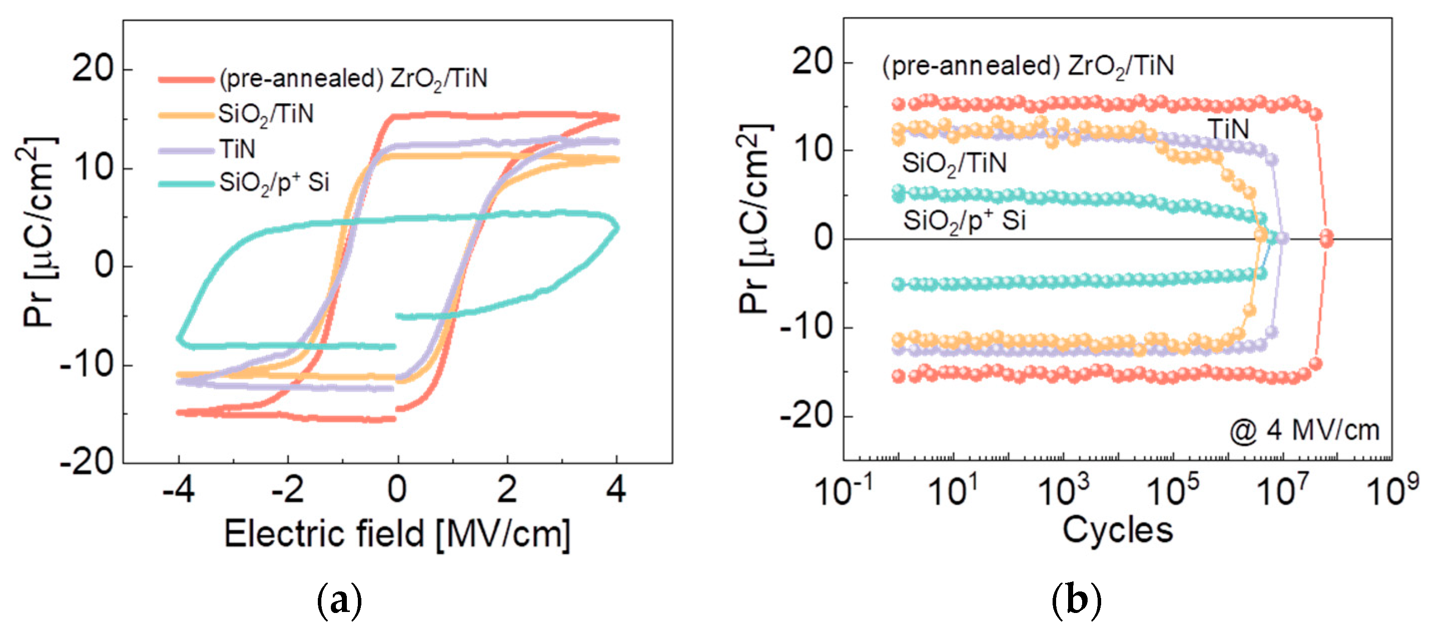
The dependence of the electric field and remanent polarization of HZO capacitors on different structural configuration is shown in Figure 2a. Notably, the W/HZO/(pre-annealed) ZrO2/TiN/p+ Si capacitor exhibits the largest remanent polarization (2Pr of 32 µC/cm2), highlighting the advantageous role of the ZrO2 interfacial layer in ferroelectric devices. Interestingly, the capacitor with a 2 nm SiO2 layer on the TiN bottom electrode demonstrates a similar Pr compared with W/HZO/TiN/p+ Si under the same electric field. Furthermore, the hysteresis curve of the W/HZO/SiO2/p+ Si capacitor presents the lowest, as well as an asymmetric, loop, which is due to electrode asymmetry. The top and bottom electrode materials (W and p+ Si) have different work functions, which leads to different barrier heights at the interfaces, resulting in different leakage currents under positive and negative bias. It is worth mentioning that all P-E curves were obtained from devices in their pristine state.
In Figure 2b, the endurance measurement results for HZO capacitors described in Figure 2a are presented. Notably, the insertion of the 2 nm ZrO2 interfacial layer results in a significant increase in the 2Pr value of the HZO capacitor. Moreover, the larger 2Pr value remains almost constant during the cycling test until a hard breakdown around 107 cycles, indicating superior endurance properties compared with the W/HZO/TiN/p+ Si capacitor and W/HZO/SiO2/TiN/p+ Si capacitor. Both samples exhibit an earlier breakdown, particularly for the W/HZO/SiO2/TiN/p+ Si capacitor, probably because the 2 nm PECVD SiO2 layer cannot form a crystallized structure at 400 °C, and this amorphous structure deteriorates the ferroelectric behavior. The W/HZO/SiO2/p+ Si capacitor shows a similar tendency, consistent with the findings reported by Toprasertpong [25]. The discernible reduction in endurance is attributed to the differences in the ferroelectric phase crystallization caused by the distinct boundary conditions of HZO during annealing.
The W/HZO/(pre-annealed) ZrO2/TiN/p+ Si capacitor exhibits superior ferroelectric performance compared to configurations with a SiO2 interfacial layer, a TiN electrode, and a p+ Si substrate. The poor ferroelectricity of the capacitor on the p+ Si substrate is ascribed to the native SiO2 layer (~1.7 nm) formed on the surface during the HZO ALD process, acting as a barrier that inhibits ferroelectric switching, which will also lead to a relative high gate leakage current with ultrathin equivalent oxide thickness (EOT). The asymmetric hysteresis loop in the positive and negative directions is due to the different electrode materials in terms of the work function of the p+ Si bottom electrode and the W top electrode. As is well known, the absence of an interfacial layer is of vital importance for good ferroelectric function, due to the fact that the interfacial layer acts as the barrier which inhibits ferroelectric switching [26]. Interestingly, the capacitor with the TiN electrode, lacking an interfacial layer, exhibits remanent polarization smaller than that with a ZrO2 interfacial layer. To unravel this phenomenon and unveil the mechanism, a comprehensive investigation was undertaken.
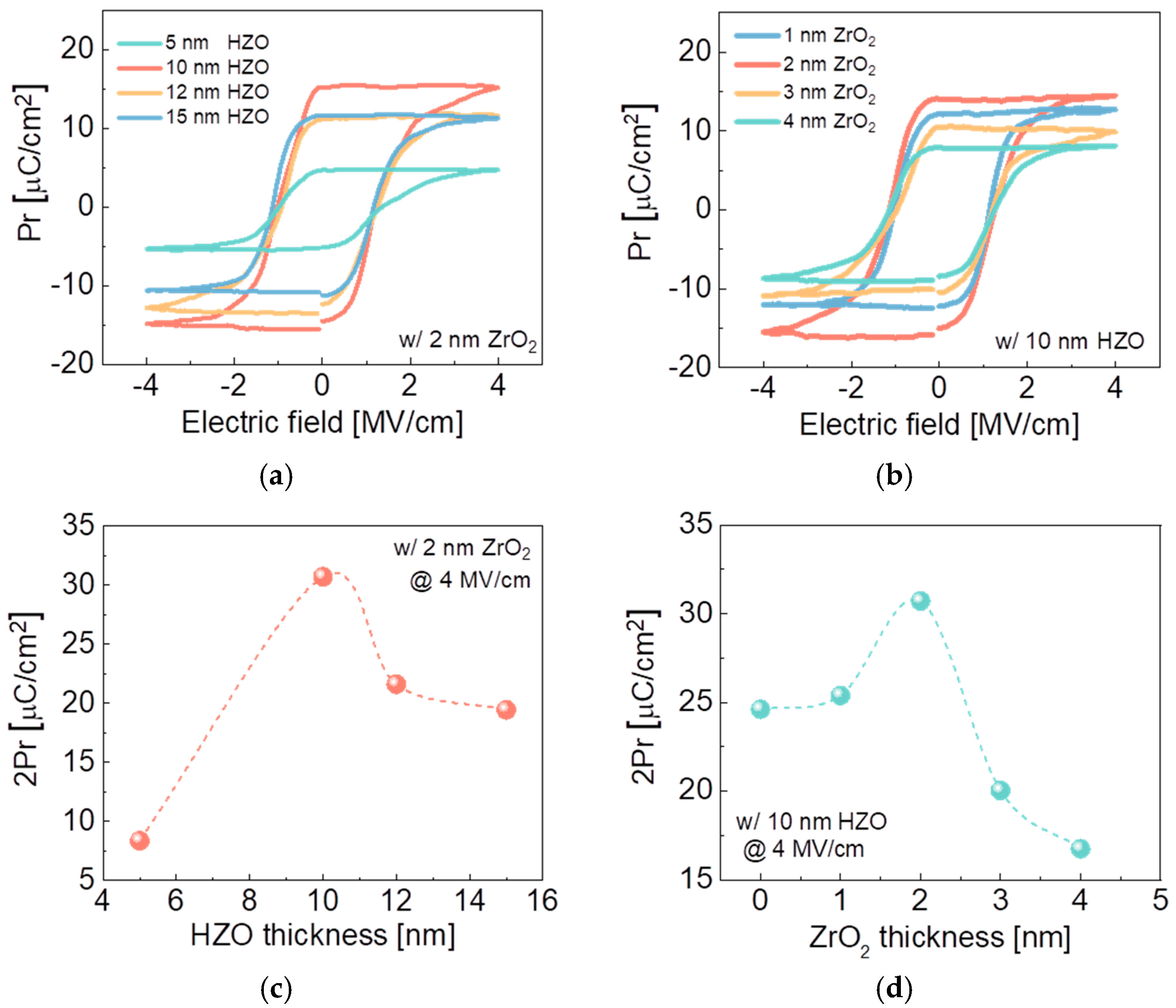
To investigate the effect of a pre-annealed ZrO2 interfacial layer on the ferroelectricity of HZO capacitors, various conditions were established. Initially, a fixed 2 nm pre-annealed ZrO2 interlayer was prepared in advance. By varying the HZO thickness from 5 to 15 nm, interesting behavior of the Pr values was observed, as shown in Figure 3a,c. The maximum 2Pr is achieved with a 10 nm HZO sample, and either increasing or decreasing the HZO thickness deteriorates the ferroelectric behavior. This is likely because 5 nm is too thin to achieve optimal ferroelectric properties, while HZO layers thicker than 10 nm result in an increased phase intensity of the peak associated with the paraelectric m-phase in the HZO films. Figure 3b depicts the influence of the ZrO2 interlayer thickness on the P-E characteristics. All the samples show well-saturated P-E hysteresis loops. The Pr values do not monotonously increase or decrease with the thickness of the ZrO2 layer. The samples with 1 nm and 2 nm interfacial layers induce a higher Pr value for the HZO film than those with thicker (3 nm and 4 nm) ZrO2 interfacial layers, as shown in Figure 3d. This is due to thicker ZrO2 layers exhibiting more antiferroelectric behavior, which could suppress the ferroelectric properties of the HZO layer. However, the 2 nm ZrO2 sample shows a higher Pr value than the 1 nm sample, likely because 1 nm ZrO2 cannot form a crystallized structure that supports the o-phase growth of HZO. Neither too-thick nor too-thin ZrO2 layers are favorable for achieving a large Pr value.
An optimal HZO thickness versus the pre-annealed ZrO2 thickness was experimentally obtained, which demonstrates superior ferroelectric properties over previous reports. In this study, a pre-annealing treatment was conducted on the ZrO2 interfacial layer before HZO deposition and subsequent HZO crystallization. To understand the impact of the annealing process on the ZrO2 interfacial layer, remanent polarization, microstructure composition, and interface morphology were investigated for W/HZO/(as-deposited) ZrO2/TiN/p+ Si and W/HZO/(pre-annealed) ZrO2/TiN/p+ Si capacitors, respectively.
The effect of pre-annealing treatment on the ZrO2 interfacial layer of the HZO capacitor’s remanent polarization is shown in Figure 4a. The W/HZO/(pre-annealed) ZrO2/TiN/p+ Si capacitor exhibits significantly larger remanent polarization, highlighting the advantage of using a pre-annealed ZrO2 interfacial layer for HZO ferroelectric devices. The GIXRD patterns of capacitors deposited on TiN, as-deposited ZrO2, and pre-annealed ZrO2 layers are characterized, as shown in Figure 4b. For samples on the as-deposited ZrO2 and TiN, a part of the m-phase is observed, while the m-phase disappeared on annealed ZrO2. Moreover, the center of the (111)o/t peak for the as-deposited ZrO2 also shows a mismatch compared with the reference sample and the annealed ZrO2, potentially causing a decrease in ferroelectric behavior. Figure 4c shows cross-sectional TEM images of W/HZO/(as-deposited) ZrO2/TiN/p+ Si and W/HZO/(pre-annealed) ZrO2/TiN/p+ Si capacitors, respectively. For the W/HZO/(as-deposited) ZrO2/TiN/p+ Si capacitor, there is a sharp interface between the HZO and ZrO2 layers due to the limited reaction and diffusion during the PDA process (see Figure 4c) for the ferroelectricity of the HZO layer. The as-deposited ZrO2 layer had an amorphous structure after the ALD process at 250 °C, and the following HZO layer was grown on this amorphous structure. During the subsequent annealing process, the as-grown ZrO2 may not provide enough capping strength. On the other hand, the HZO ferroelectric grains were crystallized in the same orientation along with the underlying pre-annealed ZrO2 grains, as shown in Figure 4c. This is likely due to the crystalline ZrO2 grains’ work as the nucleation base for the crystallization of the HZO grains during the next PDA process. It is worth mentioning that even after the PDA process, there is no intermixing of HZO and ZrO2, as shown in Figure 4d, where the Zr element distribution outranges Hf. This indicates that the crystallization of the HZO layer was promoted by the crystallized ZrO2 layer. Based on these findings, a schematic view of the working principal can be illustrated. The pre-annealing treatment enhances the bottom ZrO2 crystalline structure (Zr atoms in green), as marked by the red box (Figure 4e). The improvement in ZrO2 surface’s crystallinity introduces alterations in the atomic arrangement and lattice parameter constants, which modifies the surface energy consequently and thereby affects the phase composition. In comparison, poor ZrO2 crystallinity leads to random directional growth of the following HZO (Figure 4f), forming a polycrystalline layer that exhibits ferroelectric behavior. However, the mechanism of the phase transition driven by the surface energy has not been clearly investigated before. Developing a comprehensive understanding requires further in-depth research.

4. Conclusions

In this work, we conducted an in-depth investigation into the ferroelectric behavior of HZO capacitors incorporating a pre-annealed ZrO2 interfacial layer. The results reveal the profound impact of the pre-annealed ZrO2 interfacial layer on the ferroelectric properties of HZO. Notably, the introduction of a pre-annealed interfacial layer proves to be an effective strategy for significantly enhancing the remanent polarization in ferroelectric devices. Importantly, this advantageous effect is consistently observed across various capacitor configurations, highlighting the broad applicability of the proposed approach. In summary, the pre-annealing treatment of the ZrO2 interfacial layer offers a viable and implementable method to further optimize the behavior of ferroelectric devices. The insights gained from this study contribute valuable knowledge to the ongoing efforts in advancing the field of ferroelectric materials and their applications in the FeRAM and Fe(M)FET fields.

Author Contributions

Conceptualization, X.Y. and J.X.; methodology, X.Y. and J.Q.; software, X.Y. and W.T.; validation, X.Y.; formal analysis, X.Y. and H.H.; investigation, X.Y.; resources, X.Y.; data curation, X.Y.; writing—original draft preparation, X.Y.; writing—review and editing, X.Y. and W.T.; visualization, X.Y.; supervision, C.L. and Y.Z.; project administration, X.Y. and Z.L. All authors have read and agreed to the published version of the manuscript.

Funding

This research was supported by China Nanhu Academy of Electronics and Information Technology under Grant AFT0121042.

Data Availability Statement

Data are contained within the article.

Acknowledgments

The authors would like to thank the ZJU-CNAEIT Joint Research and Development Center of Intelligent IoT for undertaking project management, Chenhao Zhang for providing technical support in the cleanroom, and Rui Jiang for carrying out TEM measurement.

Conflicts of Interest

The authors declare no conflict of interest.

References

  1. Böscke, T.S.; Müller, J.; Bräuhaus, D.; Schröder, U.; Böttger, U. Ferroelectricity in hafnium oxide thin films. Appl. Phys. Lett. 2011, 99, 102903. [Google Scholar] [CrossRef]
  2. Müller, J.; Böscke, T.S.; Müller, S.; Yurchuk, E.; Polakowski, P.; Paul, J.; Martin, D.; Schenk, T.; Khullar, K.; Kersch, A.; et al. Ferroelectric hafnium oxide: A CMOS-compatible and highly scalable approach to future ferroelectric memories. In Proceedings of the 2013 IEEE International Electron Devices Meeting, Washington, DC, USA, 9–11 December 2013; pp. 10.8.1–10.8.4. [Google Scholar] [CrossRef]
  3. Hur, J.; Luo, Y.-C.; Tasneem, N.; Khan, A.I.; Yu, S. Ferroelectric Hafnium Zirconium Oxide Compatible With Back-End-of-Line Process. IEEE Trans. Electron Devices 2021, 68, 3176–3180. [Google Scholar] [CrossRef]
  4. Dutta, S.; Ye, H.; Khandker, A.A.; Kirtania, S.G.; Khanna, A.; Ni, K.; Datta, S. Logic compatible high-performance ferroelectric transistor memory. IEEE Electron Device Lett. 2022, 43, 382–385. [Google Scholar] [CrossRef]
  5. Chernikova, A.G.; Kozodaev, M.G.; Negrov, D.V.; Korostylev, E.V.; Park, M.H.; Schroeder, U.; Hwang, C.S.; Markeev, A.M. Improved Ferroelectric Switching Endurance of La-Doped Hf0.5Zr0.5O2 Thin Films. ACS Appl. Mater. Interfaces 2018, 10, 2701–2708. [Google Scholar] [CrossRef] [PubMed]
  6. Ambriz-Vargas, F.; Kolhatkar, G.; Thomas, R.; Nouar, R.; Sarkissian, A.; Gomez-Yáñez, C.; Gauthier, M.; Ruediger, A. Tunneling electroresistance effect in a Pt/Hf0.5Zr0.5O2/Pt structure. Appl. Phys. Lett. 2017, 110, 093106. [Google Scholar] [CrossRef]
  7. Kim, S.J.; Narayan, D.; Lee, J.; Mohan, J.; Lee, J.S.; Lee, J.; Kim, H.S.; Byun, Y.; Lucero, A.T.; Young, C.D.; et al. Large ferroelectric polarization of TiN/Hf0.5Zr0.5O2/TiN capacitors due to stress-induced crystallization at low thermal budget. Appl. Phys. Lett. 2017, 111, 242901. [Google Scholar] [CrossRef]
  8. Wang, Y.; Huang, F.; Hu, Y.; Cao, R.; Shi, T.; Liu, Q.; Bi, L.; Liu, M. Proton radiation effects on Y-doped HfO2-based ferroelectric memory. IEEE Electron Device Lett. 2018, 39, 823–826. [Google Scholar] [CrossRef]
  9. Mueller, S.; Mueller, J.; Singh, A.; Riedel, S.; Sundqvist, J.; Schroeder, U.; Mikolajick, T. Incipient ferroelectricity in Al-doped HfO2 thin films. Adv. Funct. Mater. 2012, 22, 2412–2417. [Google Scholar] [CrossRef]
  10. Martin, D.; Müller, J.; Schenk, T.; Arruda, T.M.; Kumar, A.; Strelcov, E.; Yurchuk, E.; Müller, S.; Pohl, D.; Schröder, U.; et al. Ferroelectricity in Si-doped HfO2 revealed: A binary lead-free ferroelectric. Adv. Mater. 2014, 26, 8198–8202. [Google Scholar] [CrossRef]
  11. Park, M.H.; Lee, Y.H.; Kim, H.J.; Kim, Y.J.; Moon, T.; Kim, K.D.; Müller, J.; Kersch, A.; Schroeder, U.; Mikolajick, T. Ferroelec tricity and antiferroelectricity of doped thin HfO2-based films. Adv. Mater. 2015, 27, 1811–1831. [Google Scholar] [CrossRef]
  12. Lowther, J.E.; Dewhurst, J.K.; Leger, J.M.; Haines, J. Relative stability of ZrO2 and HfO2 structural phases. Phys. Rev. B Condens. Matter. 1999, 60, 14485–14488. [Google Scholar] [CrossRef]
  13. Huan, T.D.; Sharma, V.; Rossetti, G.A.; Ramprasad, R. Path ways towards ferroelectricity in hafnia. Phys. Rev. B Condens. Matter. 2014, 90, 064111. [Google Scholar] [CrossRef]
  14. Min, H.P.; Lee, Y.H.; Mikolajick, T.; Schroeder, U.; Hwang, C.S. Review and perspective on ferroelectric HfO2-based thin films for memory applications. MRS Commun. 2018, 8, 795–808. [Google Scholar] [CrossRef]
  15. Cao, R.; Liu, Q.; Liu, M.; Song, B.; Shang, D.; Yang, Y.; Luo, Q.; Wu, S.; Li, Y.; Wang, Y.; et al. Improvement of endurance in HZO-based ferroelectric capacitor using Ru electrode. IEEE Electron Device Lett. 2019, 40, 1744–1747. [Google Scholar] [CrossRef]
  16. Sun, C.-J.; Yao, Y.-J.; Yan, S.-C.; Lin, Y.-W.; Lin, S.-W.; Hou, F.-J.; Luo, G.-L.; Wu, Y.-C. Investigation of SiGe/Si Bilayer Inverted-T Channel Gate-All-Around Field-Effect-Transistor With Self-Induced Ferroelectric Ge Doped HfO2. IEEE J. Electron Devices Soc. 2022, 10, 408–412. [Google Scholar] [CrossRef]
  17. Li, J.; Su, M.; Weng, Z.; Lan, Z.; Lee, C.; Zhao, Y. Impact of Bottom Electrode Crystallinity on Ferroelectricity of La-Doped HfO2. IEEE Electron Device Lett. 2023, 44, 1833–1836. [Google Scholar] [CrossRef]
  18. Lomenzo, P.-Y.; Takmeel, Q.; Fancher, C.-M.; Zhou, C.; Rudawski, N.-H.; Moghaddam, S.; Jones, J.-L.; Nishida, T. Ferroelectric Si-Doped HfO2 Device Properties on Highly Doped Germanium. IEEE Electron Device Lett. 2015, 36, 766–768. [Google Scholar] [CrossRef]
  19. Onaya, T.; Nabatame, T.; Sawamoto, N.; Ohi, A.; Ikeda, N.; Chikyow, T.; Ogura, A. Improvement in ferroelectricity of HfxZr1−xO2 thin films using ZrO2 seed layer. Appl. Phys. Exp. 2017, 10, 081501. [Google Scholar] [CrossRef]
  20. Onaya, T.; Nabatame, T.; Inoue, M.; Sawada, T.; Ota, H.; Morita, Y. Wake-up-free properties and high fatigue resistance of HfxZr1−xO2- based metal–ferroelectric–semiconductor using top ZrO2 nucleation layer at low thermal budget (300 °C). APL Mater. 2022, 10, 051110. [Google Scholar] [CrossRef]
  21. Onaya, T.; Nabatame, T.; Inoue, M.; Jung, Y.C.; Hernandez-Arriaga, H.; Mohan, J.; Kim, H.S.; Sawamoto, N.; Nagata, T.; Kim, J.; et al. Improvement in ferroelectricity and breakdown voltage of over 20-nmthick HfxZr1−xO2/ZrO2 bilayer by atomic layer deposition. Appl. Phys. Lett. 2020, 117, 232902. [Google Scholar] [CrossRef]
  22. Onaya, T.; Nabatame, T.; Sawamoto, N.; Ohi, A.; Ikeda, N.; Nagata, T.; Ogura, A. Improvement in ferroelectricity of HfxZr1−xO2 thin films using top- and bottom-ZrO2 nucleation layers. APL Mater. 2019, 7, 061107. [Google Scholar] [CrossRef]
  23. Chen, Y.-F.; Hu, C.-W.; Kao, Y.-C.; Kuo, C.-Y.; Wu, P.-J.; Wu, Y.-H. Wake-Up Free Ferroelectric Capacitor With Quadruple-Level Storage by Inserting ZrO2 Interlayer and Bottom Layer in HfZrOx. IEEE Electron Device Lett. 2023, 44, 400–403. [Google Scholar] [CrossRef]
  24. Lee, S.; Kim, M.; Lee, T.; Lee, T.; Bong, J.; Shin, S.; Kim, S.; Hwang, W.; Cho, B. Effect of ZrO2 interfacial layer on forming ferroelectric HfxZryOz on Si substrate. AIP Adv. 2019, 9, 125020. [Google Scholar] [CrossRef]
  25. Toprasertpong, K.; Tahara, K.; Takenaka, M.; Takagi, S. Evaluation of polarization characteristics in metal/ferroelectric/semiconductor capacitors and ferroelectric field-effect transistors. Appl. Phys. Lett. 2020, 116, 242903. [Google Scholar] [CrossRef]
  26. Tasneem, N.; Islam, M.M.; Wang, Z.; Chen, H.; Hur, J.; Triyoso, D.; Consiglio, S.; Tapily, K.; Clark, R.; Leusink, G.; et al. The Impacts of Ferroelectric and Interfacial Layer Thicknesses on Ferroelectric FET Design. IEEE Electron Device Lett. 2021, 42, 1156–1159. [Google Scholar] [CrossRef]
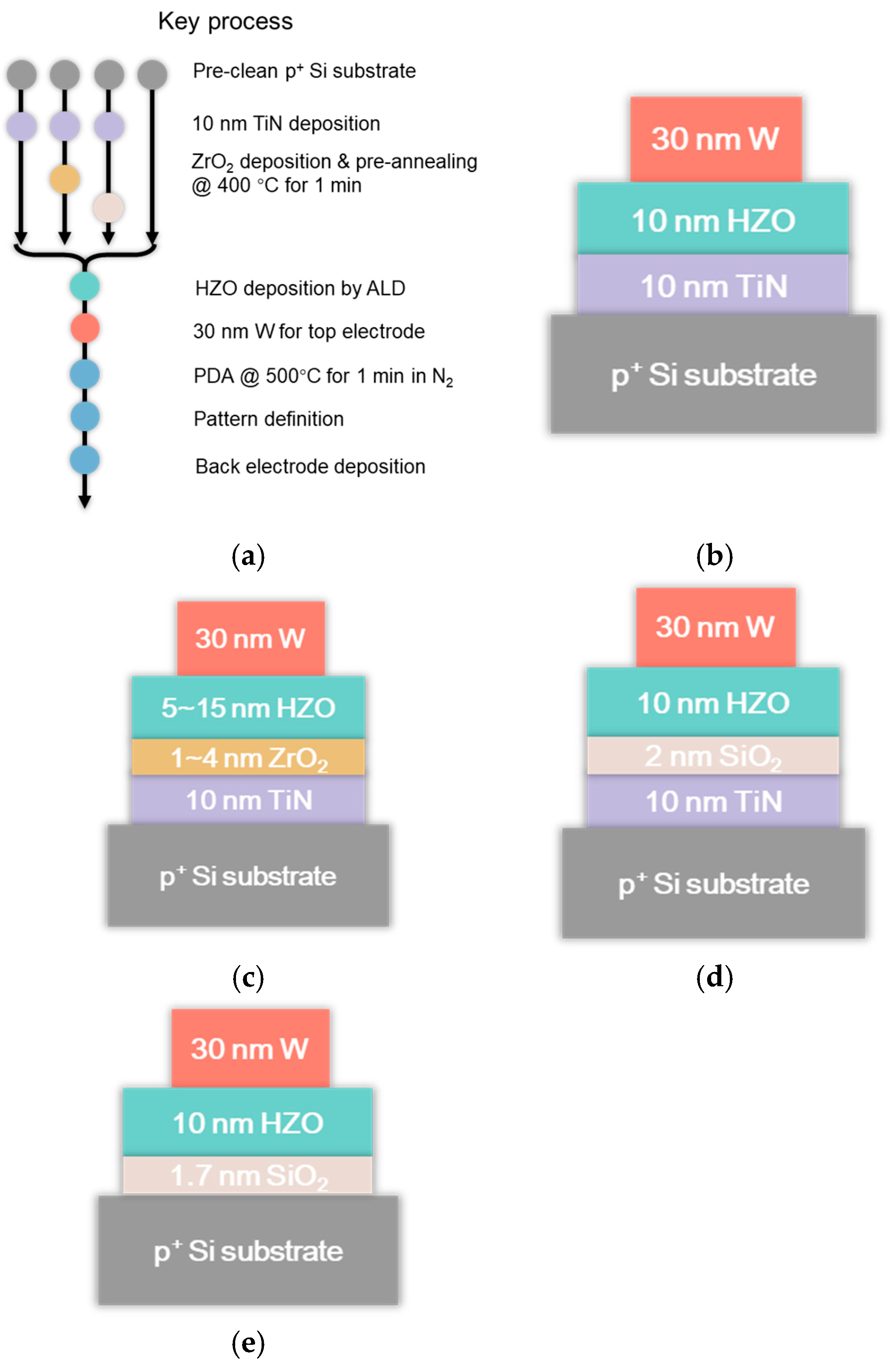
Figure 1. (a) Key process flow and schematic diagram of HZO capacitors with different structural configurations. (b) W/HZO/TiN/p+ Si, (c) W/HZO/ZrO2/TiN/p+ Si, (d) W/HZO/SiO2/TiN/p+ Si, (e) W/HZO/SiO2/p+ Si, respectively.
Electronics 13 00003 g001
Figure 2. (a) Remanent polarization (Pr) of HZO capacitors with different structural configurations under unified electric field. (b) Corresponding endurance behavior of HZO capacitors.
Electronics 13 00003 g002
Figure 3. (a) Pr of W/HZO/(pre-annealed) ZrO2/TiN/p+ Si capacitors dependent on different HZO thicknesses with a fixed pre-annealed 2 nm ZrO2 interlayer. (b) Pr of W/HZO/(pre-annealed) ZrO2/TiN/p+ Si capacitors depends on different ZrO2 thicknesses with a fixed 10 nm HZO ferroelectric layer. (c) 2Pr value vs. HZO thickness originating from (a). (d) 2Pr value vs. ZrO2 thickness achieved from (b).
Electronics 13 00003 g003
Figure 4. (a) Pr value comparison of W/HZO/(pre-annealed) ZrO2/TiN/p+ Si capacitor vs. W/HZO/(as-deposited, abbreviated to as-dep. in the figure) ZrO2/TiN/p+ Si capacitor. (b) GIXRD patterns of W/HZO/TiN/p+ Si, W/HZO/(as-deposited) ZrO2/TiN/p+ Si and W/HZO/(pre-annealed) ZrO2/TiN/p+ Si capacitors. (c) Cross-sectional TEM images of W/HZO/(as-deposited) ZrO2/TiN/p+ Si and W/HZO/(pre-annealed) ZrO2/TiN/p+ Si structures. (d) EDS elemental mapping results of W/HZO/(pre-annealed) ZrO2/TiN/p+ Si structures with the distribution of Si, Ti, Hf, Zr, and W. (e) Schematic of the pre-annealed ZrO2 layer (Zr atoms green) and the following HZO layer (Hf atoms represented in yellow). (f) Schematic of the as-deposited ZrO2 layer (Zr atoms represented in green) and the following HZO layer (Hf atoms represented in yellow).
Electronics 13 00003 g004
Disclaimer/Publisher’s Note: The statements, opinions and data contained in all publications are solely those of the individual author(s) and contributor(s) and not of MDPI and/or the editor(s). MDPI and/or the editor(s) disclaim responsibility for any injury to people or property resulting from any ideas, methods, instructions or products referred to in the content.