Article

A Multi-Frequency Low-Coupling MIMO Antenna Based on Metasurface

1
School of Science, Wuhan University of Technology, Wuhan 430070, China
2
Hubei Engineering Research Center of RF-Microwave Technology and Application, Wuhan University of Technology, Wuhan 430070, China
3
School of Information Engineering, Wuhan University of Technology, Wuhan 430070, China
4
China Research Institute of Radio-Wave Propagation, Qingdao 266107, China
5
Aerospace Information Research Institute, Chinese Academy of Sciences, Beijing 100190, China
*
Authors to whom correspondence should be addressed.
Electronics 2024, 13(11), 2146; https://doi.org/10.3390/electronics13112146
Submission received: 9 May 2024 / Revised: 28 May 2024 / Accepted: 29 May 2024 / Published: 30 May 2024
(This article belongs to the Section Microwave and Wireless Communications)

Abstract

:
In this paper, a multi-frequency MIMO antenna for 5G and Wi-Fi 6E is presented. The antenna uses a cosine-shape monopole and split-ring resonator (SRR) structure for tri-band radiation, and frequency band expansion is achieved through SRR, folded split-ring resonators (FSRR) and Archimedean spiral metasurfaces for decoupling, with which a combination of surface wave and space wave decoupling is achieved. The Archimedean spiral metasurface unit can achieve space wave decoupling in the tri-band. By adopting the method of combining space wave decoupling and surface wave decoupling, the miniature antenna is achieved. The measured results closely align with the simulated results. Specifically, maintaining a reflection coefficient of −10 dB, the measured results indicate an increase in isolation of 3.5 dB, 36.47 dB, and 6.42 dB for the frequency bands of 3.45–3.55 GHz, 5.7–5.9 GHz, and 6.75–7 GHz, respectively. Additionally, the MIMO antenna demonstrates an average efficiency of approximately 89%, with an average envelope correlation coefficient (ECC) of 0.0025. Furthermore, the antenna’s peak gain increases by 4.3 dB at 3.5 GHz, 3.8 dB at 5.8 GHz, and 1.9 dB at 6.9 GHz upon integrating the metasurface. The proposed method and structure are anticipated to contribute significantly to decoupling in multi-frequency MIMO antennas.

1. Introduction

As the requirements for the quality of communication systems continue to improve, wireless communication systems are developing rapidly; fifth-generation mobile communication technology (5G) and beyond has become a solution, with its advantages of high speed, low latency, and high communication capacity for IoT applications in various sectors. The simultaneous development of MIMO technology can effectively increase the capacity of the communication system [1]. In addition to increasing system capacity in adopted frequency bands, Wi-Fi 6E technology, as an evolution of Wi-Fi 6, offers higher capacity, and can utilize the 6 GHz frequency band from 5.925 GHz to 7.125 GHz. The demand for expanding the system capacity requires the use of many frequency bands simultaneously; multi-band devices are more advantageous than single-band ones [2], as well as antennas [3]. However, in MIMO antennas, size constraints can lead to mutual coupling if the antenna elements are placed too closely together, affecting the radiation performance of the antennas and degrading system capacity [4]. Therefore, frequency band expansion and addressing the mutual coupling issue in multi-frequency MIMO antennas are key areas of research focus.
There are many methods for designing multi-frequency antennas. In [5,6,7], by slotting, other resonant branches are formed to generate other resonant frequency bands, which is a traditional method of frequency band expansion by adding branches. In [8,9], the method of loading SRR and complementary split-ring resonators (CSRR) is used to achieve frequency band expansion. Compared to the multi-branch method, using resonant rings for frequency band expansion allows for a wider range of frequency band expansion, offering greater flexibility. Additionally, in terms of decoupling, the branches in the multi-branch method may show a mutual influence between each other. To solve the mutual coupling issue between MIMO antennas, various methods have been proposed, such as decoupling matching network (DMN), defected ground structure (DGS), electromagnetic band gap (EBG), and metamaterial decoupling. DMN was used for decoupling between antennas. In [10], the traditional technique of designing a two-level decoupling matching network was employed for antenna decoupling. In [11], lumped elements were used to design the DMN, and in [12], a compact dual-band DMN consisting of a pair of dual-band open-loop square ring resonators was proposed. This method involves directly loading active and passive networks between antenna elements to achieve decoupling. However, as the decoupling frequency points increase, the DMN tends to become complex, making it unsuitable for multi-band decoupling. In [13,14,15,16], DGS was used for decoupling, which can achieve good decoupling effects if the ground is large enough. Additionally, using EBG structures can effectively reduce mutual coupling between antennas [17,18,19,20]. However, both DGS and EBG structures require antennas to have sufficient distances between them, which is not conducive to miniaturization. In addition to the above methods, using metamaterials for decoupling is a promising method. Meta structures for electromagnetic application are deployed to develop new microwave devices [21], especially metasurfaces for antenna [22]. In [23,24], SRRs were loaded on the antenna plane for decoupling surface waves and certain space waves. In [25,26,27,28,29], the effective decoupling of antennas was achieved by loading them with metasurfaces. The decoupling method using metamaterials has a smaller impact on antenna size and radiation performance in resonance bands, and it provides good decoupling effects.
In this paper, a cosine-shape monopole is used for radiation, and SRRs are loaded to expand the frequency bands, achieving resonances in tri-band and forming a MIMO antenna. This method of expanding frequency bands will result in less influence between different frequency bands during decoupling. Subsequently, FSRR and a metamaterial surface in the form of an Archimedean spiral are used for decoupling to achieve the decoupling of space wave and surface wave, with the Archimedean spiral decoupling unit capable of achieving the decoupling of space wave in the tri-band. Ultimately, an MIMO antenna with low coupling in the tri-bands of 3.5 GHz, 5.8 GHz, and 6.9 GHz is designed for use in the 5G and Wi-Fi 6E frequency bands. The proposed method in this paper integrates the frequency band expansion function of metasurfaces with the decoupling function of space wave and surface wave, along with a specific design for frequency band expansion and decoupling structures. This is expected to contribute to the decoupling of multi-frequency MIMO antennas.
The structure of this paper is as follows: Section 2 details the analysis of the design principles, process, and decoupling mechanism of the MIMO antenna. Section 3 analyzes the performance of the antenna, comparing the performances of antennas with and without decoupling structures, such as gain patterns, efficiency, and ECC. Section 4 summarizes the design process, methods, and results of the MIMO antenna designed in this paper.

2. Antenna Design

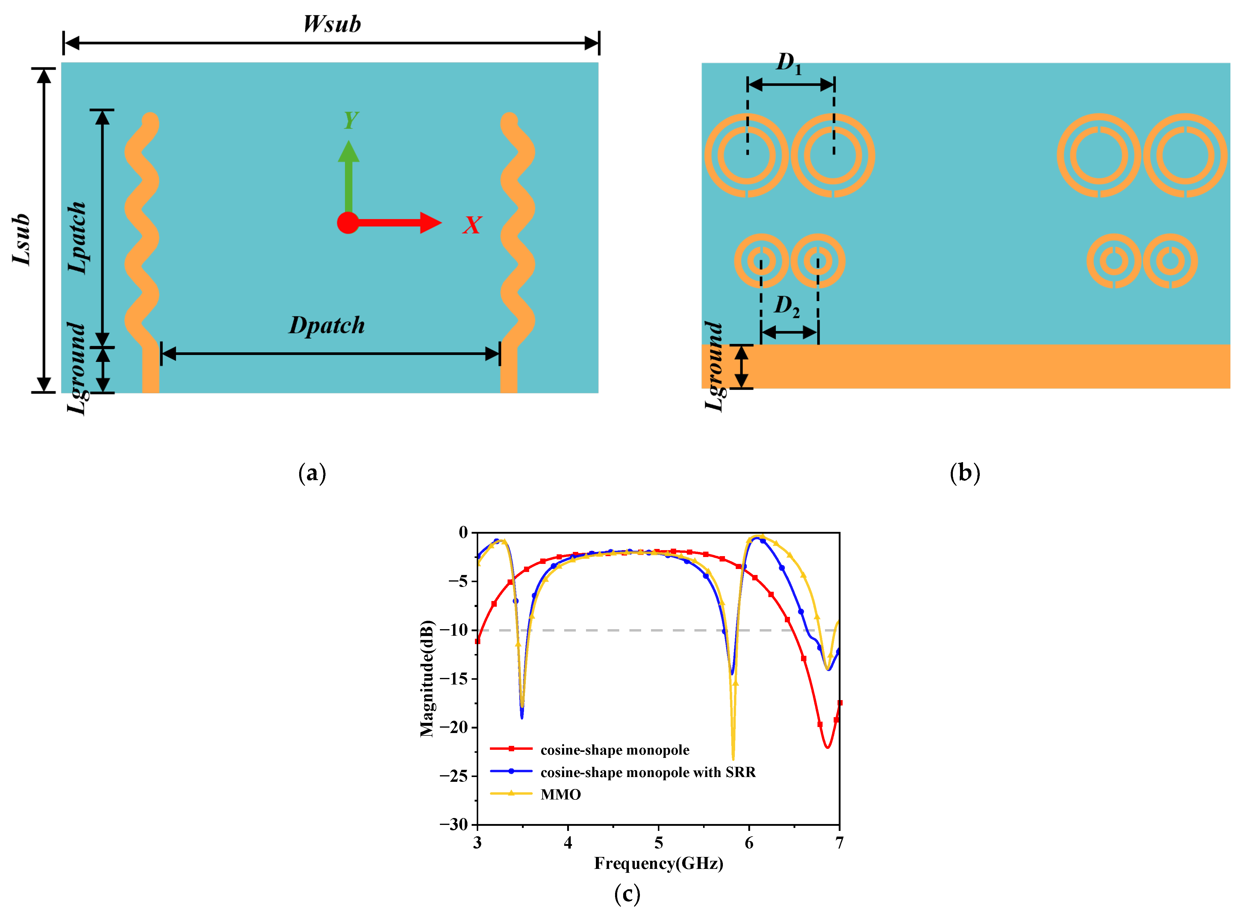
2.1. Overall of the Designed Antenna

The low-coupling MIMO antenna herein designed is capable of achieving tri-band resonance at 3.5 GHz, 5.8 GHz, and 6.9 GHz. The overall structure of the antenna is shown in Figure 1, where the tri-band resonance is generated by the cosine-shaped monopole and two SRRs on the back of the substrate. Three equally spaced FSRRs are placed between the two cosine-shape monopoles to decouple the antenna for surface waves. Additionally, a metasurface composed of Archimedean units is positioned at the Hgap below the antenna structure for space wave decoupling in the tri-band. The antenna unit and metasurface unit are loaded on an F4B substrate with a relative permittivity of 2.1 and a loss tangent of 0.002. The substrate has a thickness of 1 mm and utilizes microstrip line feeding.
The antenna is designed based on theory, and simulated and optimized using the simulation software CST 2021, with the simulation results shown in Figure 2. The simulation results in Figure 2 indicate that at 3.5 GHz, the S11 and S21 values are −17.5 dB and −16 dB, at 5.8 GHz, the S11 and S21 values are −20.8 dB and −35.9 dB, and at 6.8 GHz, the S11 and S21 values are −26 dB and −27 dB. It can be observed that the coupling is very low under effective resonance conditions.

2.2. Design of the Radiation Structure

In order to achieve antenna miniaturization and better explain decoupling design, a detailed analysis of the design process of the MIMO antenna is conducted. This includes the design of the cosine-shape monopole, frequency band-extended SRR, and the overall structure of the MIMO antenna. Figure 3, Figure 4 and Figure 5 illustrate the design process of a tri-band MIMO antenna.

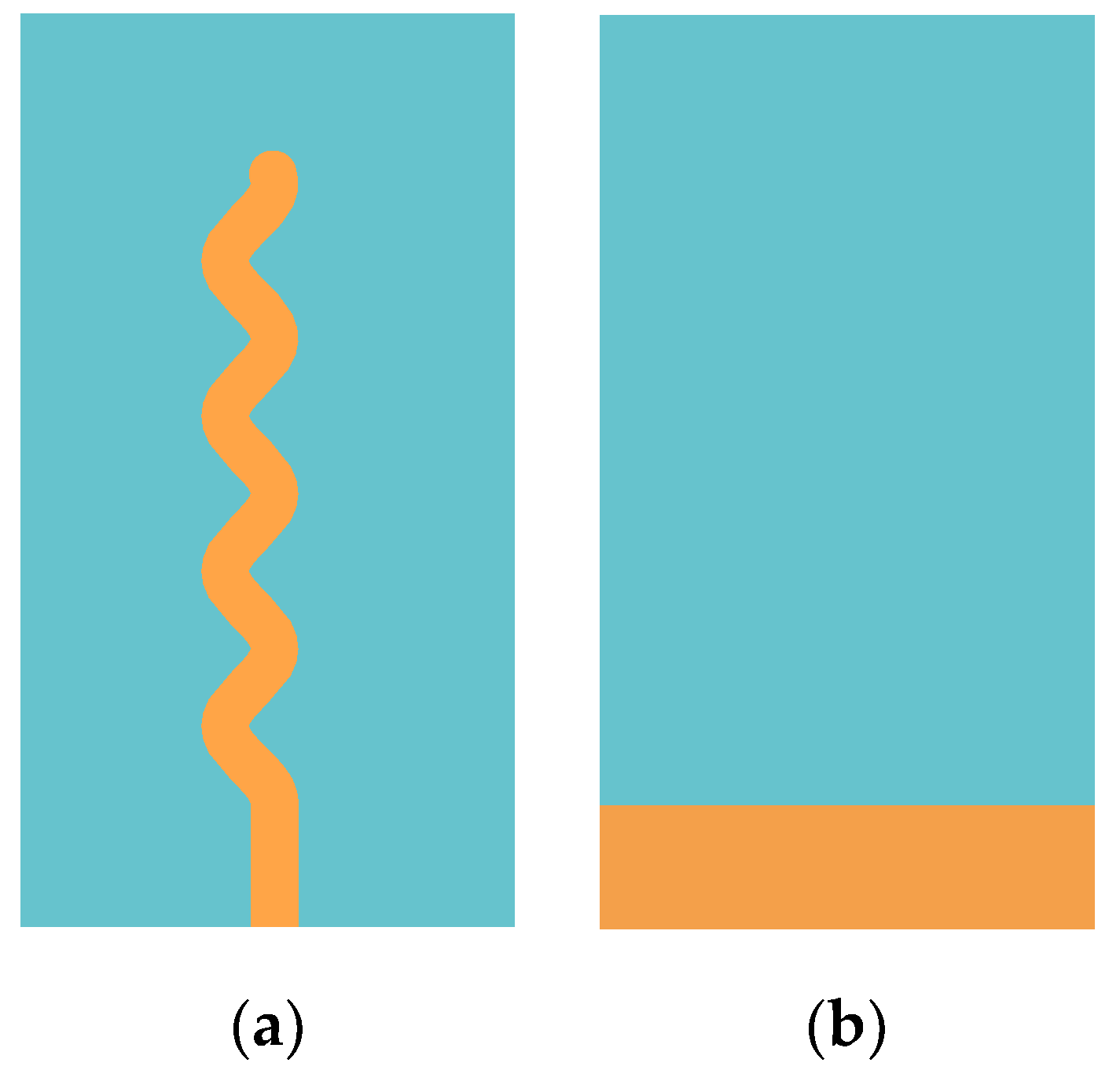
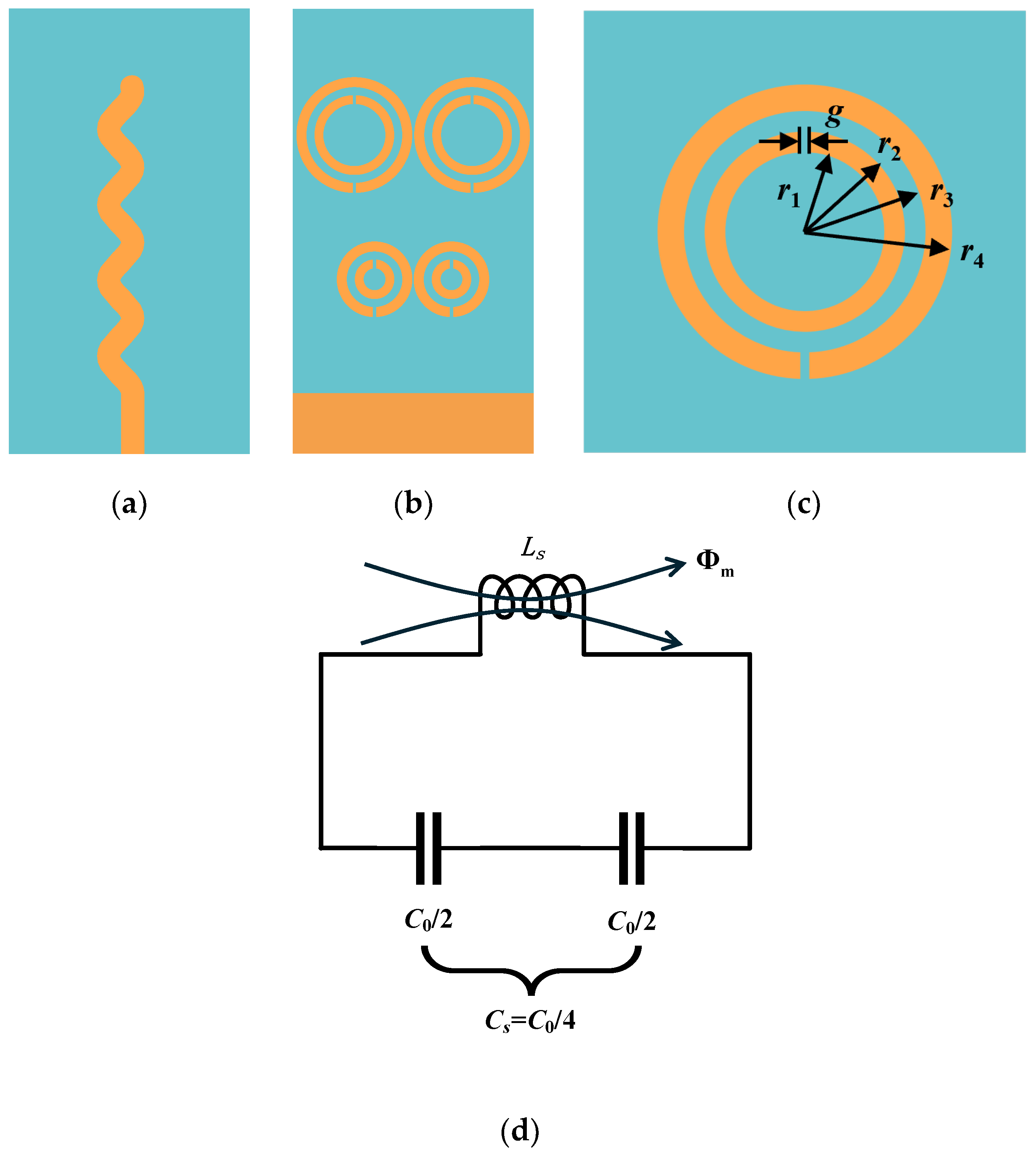
2.2.1. Cosine-Shape Monopole

In Formulas (1) and (2), Lpatch represents the length of the cosine-shaped monopole, c, f, and s represent the speed of light, frequency, and the length of each period of the cosine line, respectively, εr is the relative permittivity, A = 1 is the amplitude of the cosine, and N is the number of periods. Figure 3 and Figure 5c show the designed cosine-shaped monopole, resonating at 6.9 GHz. This curved form is beneficial for reducing the antenna size [30]. The selection of a monopole at 6.9 GHz is due to the narrow absolute bandwidth of the monopole in the low-frequency band, which leads to poor decoupling effects. Additionally, a full-wave length monopole is adopted due to the need for loading SRR.
λ = c f ε r
N = λ s
L p a t c h = N T = c × 2 π f × s × ε r
where
s = 0 T 1 + f x 2 d x = 0 2 π 1 + A sin x 2 d x
Figure 3. Cosine-shaped monopole: (a) top of the antenna unit; (b) bottom of the antenna.
Electronics 13 02146 g003

2.2.2. SRR for Frequency Band Expansion

Figure 4 shows the addition of two types of SRR structures on the back of the antenna based on Figure 3, in order to generate two additional resonant frequency bands. Compared to the method of loading branch structures, the SRR loading method provides a wider frequency range and greater flexibility for frequency band expansion. It also results in less interference between frequency bands. Importantly, this method of adding an SRR structures does not increase the overall size of the antenna. Figure 4d illustrates the equivalent circuit diagram of the SRR, where the SRR can be equivalent to an LC resonant circuit. In this circuit, Ls can be approximated as an inductance with a radius of r0 and width of r2-r1, where r0 = (r3 + r2)/2; Cs represents the capacitance between the two loops, and Cpul is the capacitance per unit length between the loops [31].
f = 1 2 π L s × C s
where
C s = C 0 / 4
C 0 = 2 π r 0 C p u l
Figure 4. Cosine-shape monopole loaded with SRR: (a) top of the antenna unit; (b) bottom of the antenna; (c) structure of the SRR unit; (d) SRR equivalent circuit.
Electronics 13 02146 g004

2.2.3. MIMO Structure

We combined two radiation units as antenna 1 and antenna 2 to form an MIMO antenna, which resonates at 3.5 GHz, 5.8 GHz, and 6.9 GHz. The S11 values are −17.37 dB, −25.43 dB, and −14.21 dB, respectively, while the S21 values are −12.5 dB, −16.57 dB, and −21.08 dB. These specifications are shown in Figure 5. The S11 in each stage of the MIMO antenna design process is depicted in Figure 5c, and the final MIMO antenna demonstrates tri-band resonance at 3.5 GHz, 5.8 GHz, and 6.9 GHz. Its specific parameters are listed in Table 1.
Figure 5. MIMO antenna: (a) top of the antenna; (b) bottom of the antenna; (c) reflection and transmission coefficients of the antenna.
Electronics 13 02146 g005

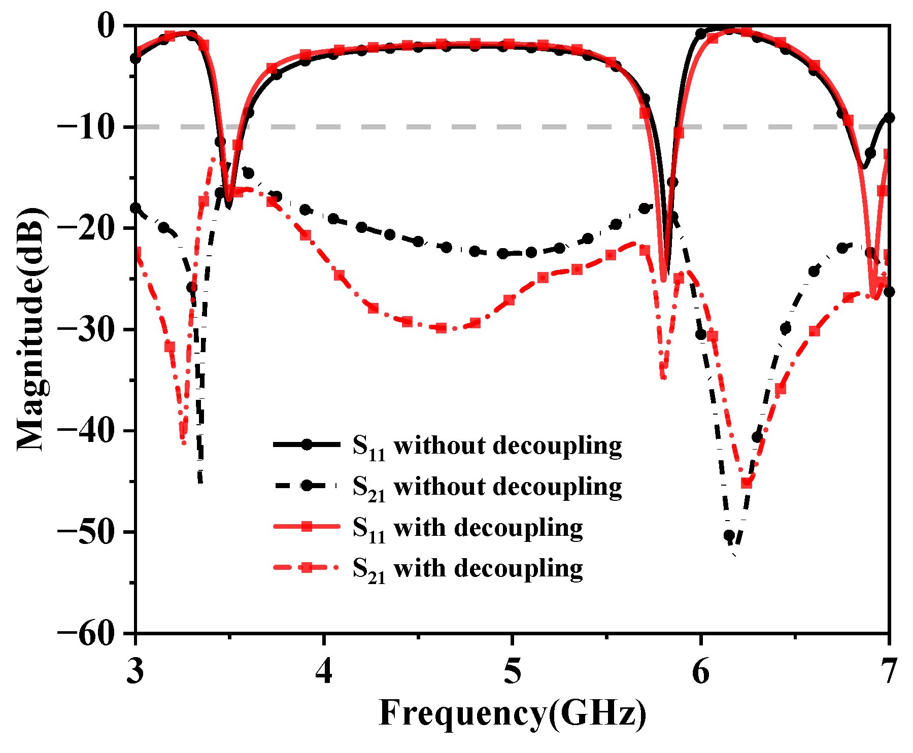
2.3. Design of the Decoupling Structures

There are two ways to reduce the coupling between antennas: reducing surface wave coupling and reducing space wave coupling [32]. After the design of the MIMO antenna radiation structure is completed, in order to reduce the coupling effect, a method of combining space wave and surface wave decoupling is used, by which two structures are designed for decoupling. The following will introduce the design process and methods for these two structures.

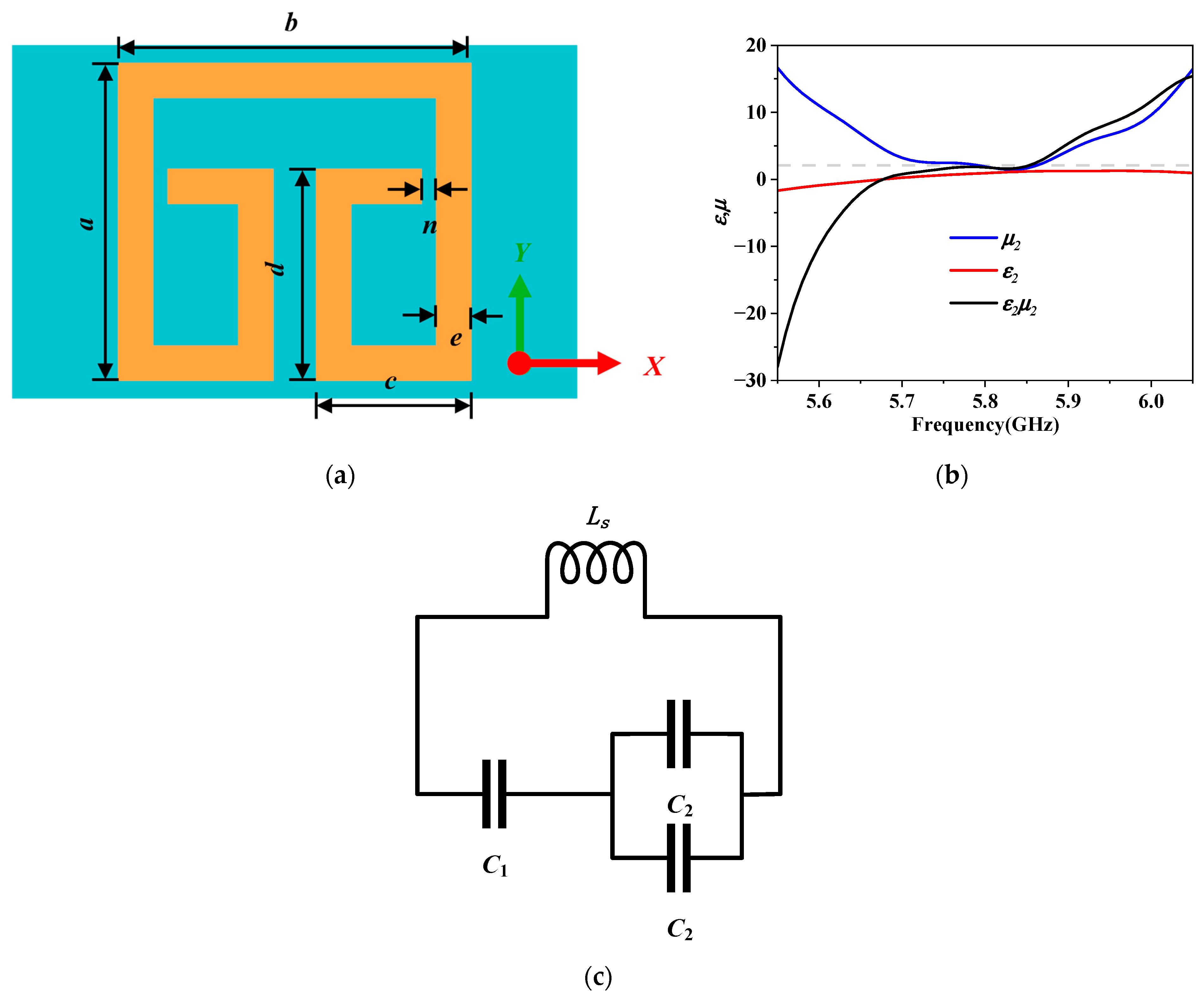
2.3.1. FSRR for Decoupling

In order to decouple the surface wave of the MIMO antennas, the proposed structure is shown in Figure 6a. Formulas (8) and (9) represent the cutoff frequencies of the TM and TE modes, where h is the thickness of the dielectric substrate, and ε1, ε2 and μ2 are the relative permittivity of the dielectric, the relative permittivity above the dielectric substrate, and the relative permeability, respectively. It can be inferred that when the space above the dielectric substrate is an air layer, ε2μ2 = 1, there will always exist a surface wave of the TM mode on the grounded dielectric substrate, because the cutoff frequency of the TM fundamental mode is 0. However, when a special dielectric layer is placed above the dielectric substrate, causing ε2μ2 = εr, the cutoff frequencies of the TE and TM modes approach infinity, making it impossible for surface wave to propagate along the dielectric interface [33]. As shown in Figure 6b, the product of the relative permittivity and relative permeability of the FSRR is approximately 2.1, around 5.8 GHz. Figure 6c shows the equivalent circuit of the FSRR, where C1 is the capacitance of the middle gap, C2 is the capacitance of the gap with a distance of n on both sides, and the inductance L is calculated from the length of the FSRR. The calculation of the resonance frequency is given by Formula (10) [34], resulting in 5.8 GHz. Therefore, the FSRR not only reduces surface waves but also resonates at 5.8 GHz, thereby offsetting some of the space wave. As shown in Figure 7, after loading the FSRR between the antennas, it can be observed that the S21 values of the MIMO antennas at 5.8 GHz improved significantly from −16.57 dB without the FSRR to −24.5 dB, with an increase in isolation of 7.93 dB, showing a clear enhancement, while S11 did not exhibit a significant increase.
f c _ T M = m c 2 h ε r ε 2 μ 2 , m = 0 , 1
f c _ T E = 2 m 1 c 4 h ε r ε 2 μ 2 , m = 1 , 2
f = 1 2 π 2 C 1 C 2 C 1 + 2 C 2 L

2.3.2. Metasurface for Decoupling

After decoupling surface wave and to some extent space wave using FSRR, a metasurface unit in the form of an Archimedean spiral is proposed for the more effective space wave decoupling of MIMO antennas. The Archimedean spiral radiates from an area where the spiral circumference equals one wavelength, known as the active region of the spiral. The low-frequency operating point of the spiral is theoretically determined by the outer radius, as given by Formula (11), where c is the speed of light, and r is the radius of the outermost ring of the antenna, with a value of 13.64 mm. Formula (12) represents the polar coordinate formula of the Archimedean spiral, indicating that the Archimedean spiral is determined by α and β, where α is 0.4 and β is 0.9. When r is the outer ring radius, the value of θ is 4.5π [34]. The loading structure is shown in Figure 8a. To illustrate the characteristics of the metasurface, simulations of the reflection coefficient and transmission coefficient of this Archimedean spiral metamaterial unit were conducted, as shown in Figure 8b. It can be seen from Figure 8b that wave reflection can be carried out in the tri-band to achieve the function of space wave decoupling. The detailed dimensional parameters of the antenna decoupling structure are listed in Table 2.
f l o w = c 2 π r ε r
R = α + β θ
x = ( α + β θ ) cos ( θ ) y = ( α + β θ ) sin ( θ )

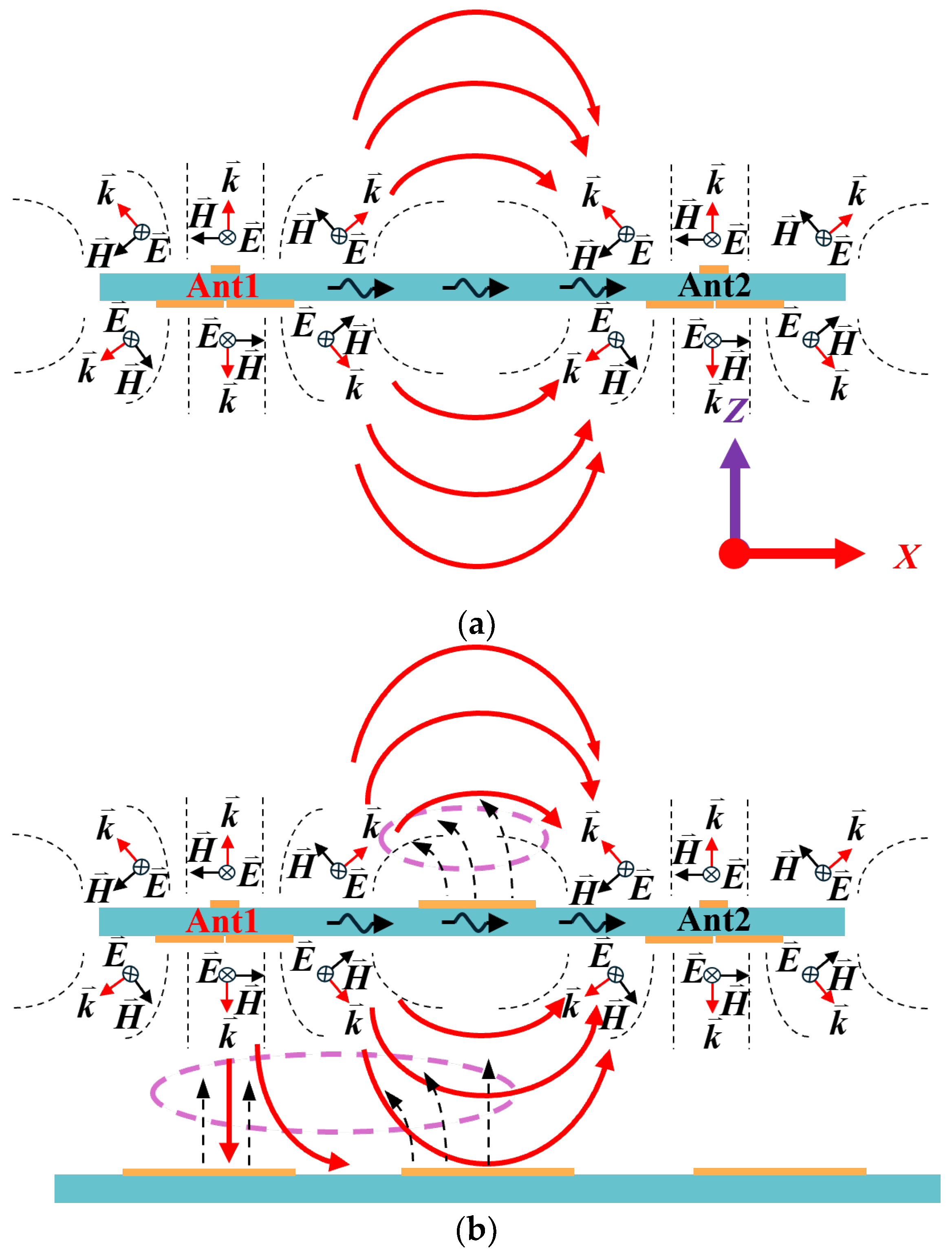
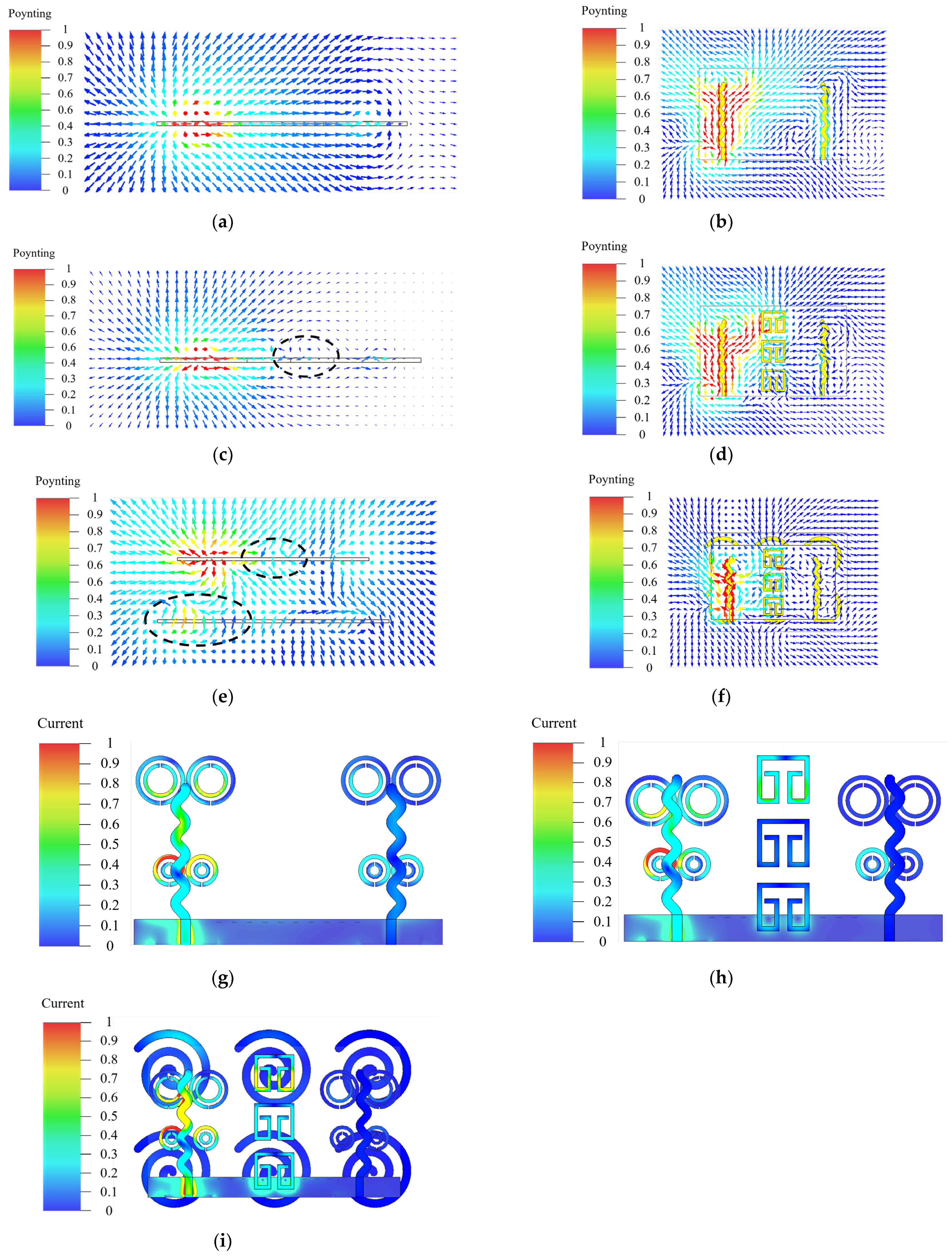
2.4. Decoupling Mechanism Analysis

According to the above conclusions, the coupling mechanism between MIMO antennas includes both surface wave coupling and space wave coupling, as illustrated in Figure 9a. The FSRR positioned between antenna 1 and antenna 2 attenuates the surface wave and contributes to radiation. Simultaneously, it generates a wave in the opposite direction of the coupling to counterbalance some of the space wave energy, resulting in the space wave decoupling effect, as depicted in the upper section of Figure 9b. Nonetheless, since the effectiveness of space wave decoupling is insufficient, a metasurface is introduced. This metasurface absorbs the space wave between antenna 1 and antenna 2, simultaneously emitting a wave in the opposite direction to neutralize the space wave coupling, as illustrated in the lower segment of Figure 9b. In summary, the mutual coupling among MIMO antenna units is mitigated through the implementation of the suggested decoupling technique involving FSRR and the metasurface.
To further elucidate the decoupling mechanism of MIMO antennas, taking 5.8 GHz as an example, the Poynting vector and surface current of MIMO antennas without any additional structure, MIMO antennas with FSRR structure, and MIMO antennas with both FSRR and metasurface loaded are compared, as shown in Figure 10. In Figure 10a,b, the energy flows from antenna 1 to antenna 2, resulting in mutual coupling. Subsequently, the loaded FSRR in Figure 10c,d generates energy flow in the opposite direction, partially canceling out the coupling. The metasurface loaded in Figure 10e,f also produces energy flow in the opposite direction, canceling out the coupling energy flow, thereby reducing the coupling strength between the antennas. Figure 10g shows the resonance at 5.8 GHz generated by the small FSRR. In Figure 10h, the decoupling FSRR induces current, playing a role in decoupling the antennas. In Figure 10i, induced currents are generated on both the FSRR and the metasurface. It can be seen from the circled part in Figure 10c,e that FSRR and Archimedean metasurface pairs generate waves in the opposite direction from the propagation direction, and cancel each other in space, thus achieving the effect of cancelling space wave and reducing the coupling of space wave between antenna elements.
In the Figure 11, since the distance between the MIMO antenna and the metasurface has a large impact on the results, the distance Hgap is parameterized next to analyze the effect of the distance between the MIMO antenna and the metasurface with respect to the isolation. It can be seen that the decoupling is best when Hgap is equal to about 20 mm.

3. Antenna Performance Analysis

The antenna was fabricated using the standard PCB fabrication process and measured using a network analyzer Keysight N5247A. The simulated S-parameters of the proposed antenna compared to the measured S-parameters are shown in Figure 12. The simulated and measured data exhibit a high level of concordance. At 3.5 GHz, the measured isolation increased by approximately 3.5 dB, and at 5.8 GHz, S21 was −53 dB, showing an increase in isolation of 36.47 dB, significantly improving the isolation between the two antennas. At 6.9 GHz, S21 decreased to −27.5 dB. The results indicate that the effective suppression of mutual coupling between the two antennas was achieved at 3.5 GHz, 5.8 GHz, and 6.9 GHz, while maintaining matching performance across the tri-band.
The antenna samples and the test environment are shown in Figure 13, where the radiation direction patterns of the unloaded and loaded metasurface are tested in a microwave anechoic chamber. The following are the procedural steps for testing the antenna:
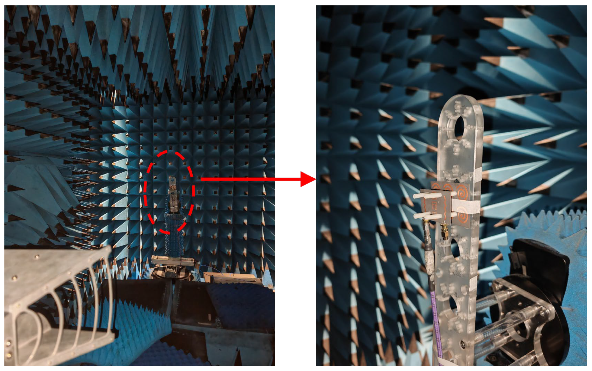
  • The signal source, network analyzer, source antenna, standard horn antenna, and antenna under test should be set up;
  • The antenna to be tested is divided into two types—the one without metasurface and the one with metasurface. The metasurface and the antenna are drilled and connected with nylon bolts. The medium between the antenna radiation structure and the metasurface is air. The two antennas are independently excited, while the other antenna is terminated with a matched load;
  • The antenna gain pattern is measured by the comparison method. The gain of the antenna to be measured is calculated by the signal power level Px received by the antenna to be measured, the signal power level Ps received by the standard horn antenna and the gain Gs of the standard horn antenna, as shown in Formula (14).
The gain direction diagram of the E-field and H-field with and without metasurface loading is shown in Figure 14. The red dotted line is the result of simulation. The red and black solid lines represent the measured images of the loaded and unloaded metasurface, respectively. It can be observed that the contour of the gain direction diagram remains similar with and without metasurface loading, indicating minimal changes in the radiation characteristics of the antenna before and after loading the metasurface. The gain increases in the direction of maximum load radiation, resulting in an improvement from 8.2 dBi to 12.5 dBi at 3.5 GHz, from 9.3 dBi to 13.1 dBi at 5.8 GHz, and from 10.3 dBi to 12.2 dBi at 6.9 GHz for the antenna’s gain due to the metasurface reducing coupling energy between the MIMO antenna elements.
G = G s + ( P x P s )
The measured efficiency and ECC of the unloaded metasurface and loaded metasurface are shown in Figure 15. When evaluating the antenna efficiency, considering the consistent simulation radiation pattern and gain performance, the efficiency can be calculated based on the measured gain, simulated gain, and directivity, as shown in Formula (15) [35]. The parameters G (θ, ϕ) and D (θ, ϕ) represent the antenna’s gain and directivity, respectively, while ecd denotes the radiation efficiency of the antenna, and functions of the spherical coordinate angles θ and ϕ. From the results, it can be seen that the efficiency of the antenna loaded with the metasurface is improved as compared to the unloaded metasurface, while the ECC is also reduced. From Figure 12, it is evident that the overall frequency of the measured antenna shifts towards the lower frequency direction after loading the metasurface. Prior to loading, the optimal decoupling frequency point is approximately 5.85 GHz; however, the frequency offset post-loading results in a narrower decoupling frequency band, leading to a slightly higher ECC at 5.85 GHz compared to when unloaded. ECC is an important parameter when measuring the degree of coupling between antennas, and is calculated as [36]
G θ , ϕ = e c d D θ , ϕ
ρ e = 4 π E 1 ( θ , ϕ ) E 2 ( θ , ϕ ) d Ω 2 4 π E 1 ( θ , ϕ ) 2 d Ω 4 π E 2 ( θ , ϕ ) 2 d Ω
where
E 1 ( θ , ϕ ) E 2 ( θ , ϕ ) = E θ 1 ( θ , ϕ ) E θ 2   ( θ , ϕ ) + E ϕ 1 ( θ , ϕ ) E ϕ 2   ( θ , ϕ )
Finally, in Table 3, the antenna proposed in this paper is compared with the reference antenna in terms of method, decoupling band, spacing (edge-to-edge), thickness, isolation, ECC, efficiency and relative bandwidth. It can be seen that the metasurface decoupling and FSRR decoupling proposed in this paper realize the decoupling of the tri-band and the isolation enhancement of 36.47 dB at 5.8 GHz, which represents a great improvement in ECC and efficiency compared to other decoupling structures and methods. The antenna decoupling structure and method proposed show high isolation and multi-band advantages. It can be seen that the decoupling method of FSRR combined with the metasurface and the design of the decoupling structure proposed in this paper feature certain innovations that make contributions to the decoupling of MIMO antennas.

4. Conclusions

In this paper, a multi-frequency low-decoupling MIMO antenna is proposed and fabricated with a loaded SRR to realize frequency band expansion, while using FSRR and a metasurface in the form of an Archimedean spiral for decoupling between MIMO antennas. Firstly, the design process and method of the MIMO antenna with frequency band expansion achieved by SRR are proposed, and then the working principle and design process of the decoupling structure FSRR and the metasurface of the MIMO antenna are introduced. The decoupling mechanism is analyzed by Poynting vectors and currents to show the decoupling effect of the metasurface, after which the effect of Hgap on the decoupling is analyzed. With a size of the antenna of 0.18 λL, the simulated and measured results show that the isolation is improved by 3.5 dB at 3.5 GHz, and when the S21 is −53 dB at 5.8 GHz, the isolation is improved by 36.47 dB, which represents a great improvement in the isolation of the two antennas, while the S21 is reduced to −27.5 dB at 6.9 GHz. In addition, the radiation efficiency of the antenna is improved in all tri-bands, and the ECC is reduced. The proposed tri-band low-coupling MIMO antenna is expected to be useful in the 5G band and the Wi-Fi 6E band.

Author Contributions

C.L.: conceptualization, supervision and project administration, analysis data, writing and editing manuscript; G.T.: investigation and design, data analysis and experiment, writing and editing the manuscript. T.X.: literature search, figures. L.C.: literature search, data collection. R.C.: data collection, literature search. L.H.: Supervision, Formal analysis. X.X.: Supervision, Methodology. All authors have read and agreed to the published version of the manuscript.

Funding

This research was supported by the National Natural Science Foundation of China (grant number 11973034).

Data Availability Statement

The original contributions presented in the study are included in the article material, further inquiries can be directed to the corresponding authors.

Conflicts of Interest

The authors declare no conflicts of interest.

References

  1. Sun, L.; Feng, H.; Li, Y.; Zhang, Z. Compact 5G MIMO mobile phone antennas with tightly arranged orthogonal-mode pairs. IEEE Trans. Antennas Propag. 2018, 66, 6364–6369. [Google Scholar] [CrossRef]
  2. Hou, Z.; Liu, C.; Zhang, B.; Song, R.; Wu, Z.; Zhang, J.; He, D. Dual-/tri-wideband bandpass filter with high selectivity and adjustable passband for 5G mid-band mobile communications. Electronics 2020, 9, 205. [Google Scholar] [CrossRef]
  3. Ojaroudi Parchin, N.; Jahanbakhsh Basherlou, H.; Alibakhshikenari, M.; Ojaroudi Parchin, Y.; Al-Yasir, Y.I.A.; Abd-Alhameed, R.A.; Limiti, E. Mobile-phone antenna array with diamond-ring slot elements for 5G massive MIMO systems. Electronics 2019, 8, 521. [Google Scholar] [CrossRef]
  4. Park, S.; Kim, B.; Kim, I.; Seo, J.B. Deploying automated frequency coordination system for WiFi 6E in South Korea: Challenges and opportunities. IEEE Commun. Mag. 2024, 62, 112–118. [Google Scholar] [CrossRef]
  5. Lu, J.H.; Huang, B.J. Planar compact slot antenna with multi-band operation for IEEE 802.16m application. Trans. Antennas Propag. 2013, 61, 1411–1414. [Google Scholar] [CrossRef]
  6. Baek, J.G.; Hwang, K.C. Triple-band unidirectional circularly polarized hexagonal slot antenna with multiple L-shaped slits. Trans. Antennas Propag. 2013, 61, 4831–4835. [Google Scholar] [CrossRef]
  7. Cao, Y.F.; Cheung, S.W.; Yuk, T.I. A multiband slot antenna for GPS/WiMAX/WLAN systems. Trans. Antennas Propag. 2015, 63, 952–958. [Google Scholar] [CrossRef]
  8. Mehdipour, A.; Denidni, T.A.; Sebak, A.R. Multi-band miniaturized antenna loaded by ZOR and CSRR metamaterial structures with monopolar radiation pattern. Trans. Antennas Propag. 2014, 62, 555–562. [Google Scholar] [CrossRef]
  9. Takemura, N. Tunable Inverted-L Antenna with split-ring resonator structure for mobile phones. Trans. Antennas Propag. 2013, 61, 1891–1897. [Google Scholar] [CrossRef]
  10. Cheng, Y.F.; Cheng, K.K.M. Compact wideband decoupling and matching network design for dual-antenna array. IEEE Antennas Wirel. Propag. Lett. 2020, 19, 791–795. [Google Scholar] [CrossRef]
  11. Wu, C.H.; Chiu, C.L.; Ma, T.G. Very compact fully lumped decoupling network for a coupled two-element array. IEEE Antennas Wirel. Propag. Lett. 2016, 15, 158–161. [Google Scholar] [CrossRef]
  12. Zhao, L.; Wu, K.L. A dual-band coupled resonator decoupling network for two coupled antennas. IEEE Trans. Antennas Propag. 2015, 63, 2843–2850. [Google Scholar] [CrossRef]
  13. Qian, B.; Chen, X.; Kishk, A.A. Decoupling of microstrip antennas with defected ground structure using the common/differential mode theory. IEEE Antennas Wirel. Propag. Lett. 2021, 20, 828–832. [Google Scholar] [CrossRef]
  14. Wei, K.; Li, J.Y.; Wang, L.; Xing, Z.J.; Xu, R. Mutual coupling reduction by novel fractal defected ground structure bandgap filter. IEEE Trans. Antennas Propag. 2016, 64, 4328–4335. [Google Scholar] [CrossRef]
  15. Qian, B.; Chen, X.; Zhao, L.; Chen, J.; Kishk, A.A. Reduced cross-polarization and backside radiations for rectangular microstrip antennas using defected ground structure combined with decoupling structure. IEEE Antennas Wirel. Propag. Lett. 2023, 22, 517–521. [Google Scholar] [CrossRef]
  16. Niu, Z.; Zhang, H.; Chen, Q.; Zhong, T. Isolation enhancement for 1×3 closely spaced E-plane patch antenna array using defect ground structure and metal-vias. IEEE Access 2019, 7, 119375–119383. [Google Scholar] [CrossRef]
  17. Tan, X.; Wang, W.; Wu, Y.; Liu, Y.; Kishk, A.A. Enhancing isolation in dual-band meander-line multiple antenna by employing split EBG structure. IEEE Trans. Antennas Propag. 2019, 67, 2769–2774. [Google Scholar] [CrossRef]
  18. Yang, X.; Liu, Y.; Xu, Y.X.; Gong, S.X. Isolation enhancement in patch antenna array with fractal UC-EBG structure and cross slot. IEEE Antennas Wirel. Propag. Lett. 2017, 16, 2175–2178. [Google Scholar] [CrossRef]
  19. Qiu, L.; Zhao, F.; Xiao, K.; Chai, S.L.; Mao, J.J. Transmit–receive isolation improvement of antenna arrays by using EBG structures. IEEE Antennas Wirel. Propag. Lett. 2012, 11, 93–96. [Google Scholar]
  20. Dey, S.; Dey, S.; Koul, S.K. Isolation improvement of MIMO antenna using novel EBG and hair-pin shaped DGS at 5G millimeter wave band. IEEE Access 2021, 9, 162820–162834. [Google Scholar] [CrossRef]
  21. Bukhari, S.S.; Vardaxoglou, J.; Whittow, W. A metasurfaces review: Definitions and applications. Appl. Sci. 2019, 9, 2727. [Google Scholar] [CrossRef]
  22. Chen, Z.N. Microwave Metalens antennas. Proc. IEEE 2023, 111, 978–1010. [Google Scholar] [CrossRef]
  23. Wang, Z.; Li, C.; Wu, Q.; Yin, Y. A metasurface-based low-profile array decoupling technology to enhance isolation in MIMO antenna systems. IEEE Access 2020, 8, 125565–125575. [Google Scholar] [CrossRef]
  24. Munusami, C.; Venkatesan, R. A compact boat shaped dual-band MIMO antenna with enhanced isolation for 5G/WLAN application. IEEE Access 2024, 12, 11631–11641. [Google Scholar] [CrossRef]
  25. Liu, F.; Guo, J.; Zhao, L.; Huang, G.L.; Li, Y.; Yin, Y. Dual-band metasurface-based decoupling method for two closely packed dual-band antennas. IEEE Trans. Antennas Propag. 2020, 68, 552–557. [Google Scholar] [CrossRef]
  26. Wang, Z.; Li, C.; Yin, Y. A meta-surface antenna array decoupling (MAAD) design to improve the isolation performance in a MIMO system. IEEE Access 2020, 8, 61797–61805. [Google Scholar] [CrossRef]
  27. Wang, Z.; Tu, Z.H.; Yuan, Z.; Chen, F.C. Decoupling and wide-angle scanning design of a millimeter-wave phased array using square-ring metasurface. IEEE Antennas Wirel. Propag. Lett. 2023, 22, 1828–1832. [Google Scholar] [CrossRef]
  28. Abdullah, M.; Koziel, S. A novel versatile decoupling structure and expedited inverse-model-based re-design procedure for compact single-and dual-band MIMO antennas. IEEE Access 2021, 9, 37656–37667. [Google Scholar] [CrossRef]
  29. Sokunbi, O.; Kishk, A.A. Millimeter-wave me-dipole array antenna decoupling using a novel metasurface structure. IEEE Access 2023, 11, 129854–129865. [Google Scholar] [CrossRef]
  30. Zheng, M.; Wang, H.; Hao, Y. Internal hexa-band folded monopole/dipole/loop antenna with four resonances for mobile device. IEEE Trans. Antennas Propag. 2012, 60, 2880–2885. [Google Scholar] [CrossRef]
  31. Baena, J.D. Equivalent-circuit models for split-ring resonators and complementary split-ring resonators coupled to planar transmission lines. Trans. Microw. Theory Tech. 2005, 53, 1451–1461. [Google Scholar] [CrossRef]
  32. Askarian, A.; Yao, J.; Lu, Z.; Wu, K. Surface-wave control technique for mutual coupling mitigation in array antenna. IEEE Microw. Wirel. Compon. Lett. 2022, 32, 623–626. [Google Scholar] [CrossRef]
  33. Jafargholi, A.; Jafargholi, A.; Choi, J.H. Mutual coupling reduction in an array of patch antennas using CLL metamaterial superstrate for MIMO applications. Trans. Antennas Propag. 2019, 67, 179–189. [Google Scholar] [CrossRef]
  34. Caswell, E.D. Design and Analysis of Star Spiral with Application to Wideband Arrays with Variable Element Sizes. Ph.D. Thesis, Virginia Tech, Blacksburg, VA, USA, 2001. [Google Scholar]
  35. Constantine, A.B. Antenna Theory: Analysis and Design, 3rd ed.; John Wiley & Sons: Hoboken, NJ, USA, 2005; pp. 65–66. [Google Scholar]
  36. Iqbal, A.; A Saraereh, O.; Bouazizi, A.; Basir, A. Metamaterial-based highly isolated MIMO antenna for portable wireless applications. Electronics 2018, 7, 267. [Google Scholar] [CrossRef]
Figure 1. Structure of the antenna.
Electronics 13 02146 g001
Figure 2. Simulation results.
Electronics 13 02146 g002
Figure 6. FSRR of decoupling: (a) structure of the FSRR unit; (b) the relative permittivity and relative permeability of FSRR; (c) equivalent circuit of FSRR.
Electronics 13 02146 g006
Figure 7. MIMO antennas with decoupled FSRR: (a) top of the antenna unit; (b) bottom of the antenna unit; (c) reflection and transmission coefficients of the antenna.
Electronics 13 02146 g007
Figure 8. Archimedes spiral metasurface: (a) structure of the metasurface; (b) reflection and transmission coefficients of the metasurface.
Electronics 13 02146 g008
Figure 9. The decoupling principle: (a) without decoupling structure; (b) decoupling structure.
Electronics 13 02146 g009
Figure 10. Poynting vectors and the current: (a) Poynting vector front view of the unloaded structure; (b) Poynting vector top view of the unloaded structure; (c) Poynting vector front view of the structure loaded with FSRR; (d) Poynting vector top view of the structure loaded with FSRR; (e) Poynting vector front view of the structure loaded with FSRR and metasurface; (f) Poynting vector top view of the structure loaded with FSRR and metasurface; (g) the current of the unloaded structure; (h) the current of the loaded FSRR; (i) the current of the loaded FSRR and metasurface.
Electronics 13 02146 g010
Figure 11. Effects of different Hgap on S21.
Electronics 13 02146 g011
Figure 12. Simulated and measured S-parameters of the proposed antenna.
Electronics 13 02146 g012
Figure 13. Photograph of radiation pattern measurement.
Electronics 13 02146 g013
Figure 14. Measured radiation patterns of the antenna arrays without and with metasurface at (a) 3.5 GHz E-plane; (b) 5.8 GHz E-plane; (c) 6.9 GHz E-plane; (d) 3.5 GHz H-plane; (e) 5.8 GHz H-plane; (f) 6.9 GHz H-plane.
Electronics 13 02146 g014
Figure 15. Measured total efficiency and calculated ECC of the antenna without and with metasurface.
Electronics 13 02146 g015
Table 1. The detailed dimension (mm) of the MIMO antenna radiation structure.
VariableValueVariableValueVariableValue
Wsub60Lground5r21.628/2.648
Lsub37D18.4r32.328/3.348
Lpatch25.5D26.4r43.128/4.148
Dpatch28r10.828/1.848g0.1
Table 2. Decoupled structure detailed parameters (mm).
VariableValueVariableValueVariableValue
Wsub275d6β0.9
Lsub250e0.85θ4.5 π
a9n0.5e22
b10.5t3
c4α0.4
Table 3. Comparison of reference and proposed decoupling structures.
Ref.MethodFrequencies
(GHz)
Spacing (Edge-to-Edge)Height
(mm)
Enhancement
(dB)
ECCEfficiencyRelative
Bandwidth
[10]DMN3.3–3.70.31 λ0011–16 dB<0.0485%5.5%
[13]DGS2.480.38 λ0020 dB<0.0368%2%
[17]EBG3.48/4.880.46 λL/0.65 λH02.8 dB/25 dB<0.08985%5.7%/9%
[14]SRR5–60.06 l00.05 λ015 dB<0.165–74%27.5%
[16]Metasurface2.6/3.50.008 λL/0.01 λH0.095 λL30.4 dB/10.6 dB<0.688%/67.5%7.5%/5.7%
Pro.FSRR/Metasurface3.5/5.8/6.90.18 λL/0.29 λM/0.35 λH0.12 λL3.5 dB/36.47 dB/6.42 dB<0.00584%/94%/88%3%/5.8%/9.5%
Note: λ0 represents the free-space wavelength of a single band, while λL, λM and λH represent the wavelengths of the low, intermediate, and high bands of the tri-band-free space, respectively.
Disclaimer/Publisher’s Note: The statements, opinions and data contained in all publications are solely those of the individual author(s) and contributor(s) and not of MDPI and/or the editor(s). MDPI and/or the editor(s) disclaim responsibility for any injury to people or property resulting from any ideas, methods, instructions or products referred to in the content.

