Article

Continuous Time Simulation and System-Level Model of a MVDC Distribution Grid Including SST and MMC-Based AFE

1
Hitachi Energy, Spinnereistrasse 3, 5300 Turgi, Switzerland
2
HEIG-VD, University of Applied Sciences of Western Switzerland, Route de Cheseaux 1, CP, 1401 Yverdon-les-Bains, Switzerland
*
Author to whom correspondence should be addressed.
Electronics 2024, 13(11), 2193; https://doi.org/10.3390/electronics13112193
Submission received: 1 April 2024 / Revised: 16 May 2024 / Accepted: 27 May 2024 / Published: 4 June 2024
(This article belongs to the Special Issue Multi-Level Power Converters Systems)

Abstract

:
Medium-voltage DC (MVDC) technology has gained increasing attention in recent years. Power electronics devices dominate these grids. Accurate simulation of such a grid, with detailed models of switching semiconductors, can quickly became very time-consuming, according to the number of connected devices to be simulated. A simulation approach based on interactions on a continuous time model can be very interesting, especially for developing a system-level control model of such a modern MVDC distribution grid. The aim of this paper is to present all the steps required for obtaining a continuous time modelling of a +/−10 kV MVDC grid case study, including a solid-state transformer (SST)- and modular multilevel converter (MMC)-based active front end (AFE). An additional aim of this paper is to supply educational content about the use of the continuous time simulation approach, thanks to a detailed description of the various devices modelled into the presented MVDC grid. The results of a certain number of simulation scenarios are eventually presented.

1. Introduction

Medium-voltage DC (MVDC) technology has gained increasing attention in recent years, allowing the enhancement of power distribution capacity, improvement in operation flexibility, and increased power quality in the distribution grid. Most renewable energy generations (REGs), and modern electronics loads (e.g., EVs) are DC, in order to integrate those elements into a DC distribution permit to avoid double conversions.
A simulation approach based on interactions in a continuous time model can be highly advantageous, particularly for the development of a system-level control model of a modern medium-voltage direct current (MVDC) distribution grid. The methodology proposed in this paper enables real-time analysis and dynamic response assessment, capturing the intricate behaviour of electrical components and control mechanisms under varying operational conditions. Additionally, this approach facilitates the optimisation of control strategies and enhances the reliability and efficiency of the MVDC grid without requiring very detailed, time-consuming models. Consequently, continuous time simulation serves as a critical tool in the advancement and implementation of robust, high-performance MVDC distribution systems.
The aim of this study is to describe a tool that allows the study of MVDC microgrids with quite a detailed level of accuracy in terms of system dynamics. The modelling allows a gain by a factor of 20 in simulation effort when compared to a switching model, but this is not the highlight of this study. We would rather highlight the possibilities that this tool allows in terms of simulation and implementing Python-based power management that continuously interacts with the model.

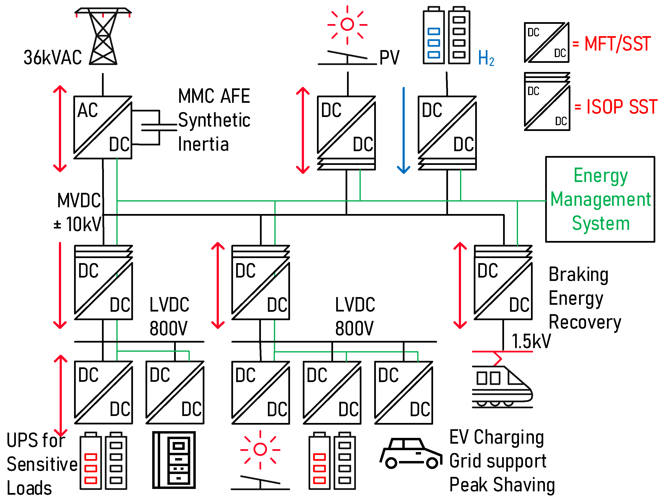
1.1. Prospects and Challenges in MVDC

In [1], the state of the art of recent research and applications of MVDC distribution systems in power grids (up to 2019) are presented. The paper includes planning and evaluation, main circuits, key equipment, control aspects and protection. Several other papers have been published in the last years.
One of the key technologies of MVDC is the solid-state transformer. This is a widely examined subject in the literature. The SST enables meshed hybrid microgrids (MHMs) through multiport and multi-stage conversion. MHMs outperform conventional hybrid AC–DC microgrids (HMGs), but the SST’s complexity requires accurate modelling for optimal power flow in energy management systems. In [2], the authors proposed an equivalent power flow model to facilitate MHM management problems, integrated with a hierarchical control architecture. The authors validate the ST’s accuracy and MHM’s performance for optimal scheduling. In [3], the authors propose a start-up method for smart transformers in low-voltage meshed hybrid grids, ensuring seamless transition from islanded to grid-connected mode. The method involves step-by-step activation of converters, with a centralised controller orchestrating the process to maintain stability. In [4], the decentralised integration of distributed generation and loads poses challenges in maintaining power flow and quality. Meshed hybrid microgrids, facilitated by smart transformers, offer a promising solution for enhancing power systems. This article assesses the performance of a smart transformer-based microgrid interconnected via medium-voltage dc-link, proposing coordinated operation to enhance system reliability and control simplicity. Simulation and experimental results validate the effectiveness of the proposed approach. In [5], the authors examine a DC solid-state transformer based on a three-level power module for interconnecting MVDC and LVDC systems, featuring low-voltage IGBTs for the MV, reducing the need for medium-frequency transformers and resonant capacitors. The system integrates an active front end for voltage regulation, with power control and DC fault handling on the MVDC side. A 7 kW prototype validates the effectiveness of the proposed solution through experimental testing.
In an analogous way, the use of multilevel converters in MVDC application has also been widely studied. In [6], a novel DC transformer for linking MVDC and LVDC grids, employing series-connected half-bridge SM branches on the MV side to reduce SM count and voltage stress is presented. It utilises quasi-square-wave modulation and phase-shifted control for bidirectional power transmission and zero-voltage switching (ZVS). The design ensures low current stress and ZVS over a wide voltage range, with a smooth transition strategy to mitigate current spikes. Simulation and prototype testing validate the proposed DCT’s efficacy. In [7], the authors present a multiport DC solid-state transformer to connect DC units directly to the MVDC bus, reducing the cost and the number of converters. High-frequency transformers provide galvanic isolation for DC units. An LC branch resolves voltage imbalance on the MVDC side, validated through simulations and experiments. Reference [8] introduces a novel DC transformer structure based on MMC and cascaded H-bridge for low-voltage DC distribution systems, analysing different control cases. Equal and unequal carrier-phase-shift pulse-width modulation methods are proposed to produce five-level voltage waveforms. Quasi-square-wave modulation reduces insulation design difficulty and voltage stress. Simulation results validate the proposed structure and control strategy. A modular multilevel DC–DC converter with inherent bipolar operation for MVDC has been presented in [9] the authors introduce a modular multilevel DC–DC converter with inherent bipolar operation capability for interconnecting bipolar MVDC and LVDC grids. Employing a centre-tapped high-frequency interface transformer on the MV side enables independent regulation of power flows for each MVDC pole, enhancing reliability. The proposed operation method, based on flux DC-bias cancellation, simplifies control, and ensures at least 50% rated power delivery even in case of pole failure. Simulation and experimental validation of the MMDC’s bipolar operation scheme confirm its effectiveness.
The problem of the protection of MVDC devices during faults is another large field of study. In [10], a MMC-based SST is used to facilitate flexible power flow in hybrid AC/DC grids. This article proposes a fault-mode control strategy for uninterrupted power supply in M-SSTs during MVDC short-circuit faults, enhancing reliability. The topology includes a hybrid MMC with bidirectional DC–DC converters, ensuring continuous power interaction between MVAC and LVDC ports. Improved capacitor voltage balance control and modulation scheme maintain harmonic performance. Simulation and experimental results validate the effectiveness of the proposed approach. The problem of realising a fault-tolerant SST is discussed in [11]. This article presents a fault-tolerant SST for MVDC electric distribution systems, ensuring robustness and higher power density. A 6-MW SiC-MOSFET-based SST using MF transformer isolation is proposed for normal operation during partial faults. Small-signal modelling, simulations, and experimental validation confirm the feasibility and performance of the proposed structure and control system, promising enhanced power density for critical MVDC applications like subsea electrification. In [12], a hybrid DC circuit breaker for MVDC applications is described. The paper addresses two key challenges in medium-voltage direct current (MVDC) distribution networks: flexible power flow control and fault protection. A power flow controller is introduced to regulate power flow and mitigate fault currents during DC faults. A coordination strategy between series-parallel PFC and hybrid DC circuit breaker is proposed to suppress fault current rise and reduce the breaking current. Mathematical modelling, simulation, and verification demonstrate the effectiveness of the coordination strategy, enhancing fault protection in MVDC distribution networks. In [13], a DC fault ride-through method for MVDC distribution systems is presented. The paper proposes a practical DC fault ride-through method by converting redundant half-bridge submodules to full-bridge submodules in HB-MMCs, coupled with hybrid DC circuit breakers (CBs). The characteristics of DC fault currents with the proposed FRT method are discussed and validated through simulations, offering an effective and cost-efficient solution for MMC–MVDC systems. The problem of the partial discharge on the DC cables, from an experimental point of view, is studied in [14]. This research examines the potential of DC supply to reduce cable size without compromising service life, crucial for applications with weight and size constraints. Experimental data on partial discharges (PD) from medium-voltage cables demonstrate that DC supply may offer favourable conditions compared to AC, particularly in mitigating PD from internal voids and delamination. In [15], the authors introduce a novel fast-acting backup protection strategy for hybrid AC–DC distribution networks. By analysing impedance from the AC-side, a unique characteristic is established for faults on the DC-side of embedded MVDC links. Verified software settings are deployed on distance protection relays to ensure stable operation during AC-side faults, with altered tripping logic to provide rapid detection of DC faults within 40 ms. Confirmatory checks reduce bad operation risks, validated through trials on a test system derived from an actual distribution network.
High-voltage multi-terminal DC systems address growing energy demands by efficiently transmitting bulk power and integrating diverse energy sources. However, susceptibility to DC faults, particularly pole-to-pole faults, presents a technical hurdle. Those aspects are studied in [2], where a cost-effective method for clearing and isolating DC faults in MMC-based MTDC grids without relying on expensive DC circuit breakers is proposed. Through RTDS simulations, the effectiveness of the proposed approach in managing DC faults and restoring grid functionality is demonstrated.
Another important issue of MMC converters is the minimisation of the circulating current. The MMC offers scalability and reduced harmonic distortion compared to other topologies. However, using carrier-based pulse-width modulation increases control complexity and memory requirements due to there being more sub-modules and synchronisation challenges. In [16], an enhanced 2N + 1 pulse-width modulation approach with simplified control and a strategy to suppress circulating currents is proposed. Experimental validation confirms reduced complexity, maintained output performance, and effective circulating of current suppression with the proposed method.
MMC suitable for multi-terminal high-voltage direct current transmission systems or MVDC distribution systems are studied in [17]. This paper presents a decoupled control strategy for a double-T topology DC–DC suitable for MT-HVDC transmission systems or MVDC distribution systems. The strategy aims to minimise input current harmonics and eliminate output AC common-mode voltage, crucial for MT-HVDC systems. By injecting two circulating AC currents and two DC currents, it achieves energy balance within the converter arms and topology. Simulation results validate the effectiveness of the proposed system.
A three-port PET with integrated MMC arm inductors and a high-frequency transformer, enabling direct access to the LVDC port, is presented in [18]. The magnetic integration reduces volume and active switches, leading to a compact design and cost reduction. Compared to existing PETs, it achieves over 60% reduction in magnetic volume and more than 19% in device cost. It is suitable for AC/DC hybrid distribution with MVDC, MVAC, and LVDC ports, especially for moderate power scenarios. Simulation and experimental results verify the feasibility of the proposed PET.

1.2. System-Level Modelling and Simulation

With the increasing complexity of the modern MVDC distribution grid, detailed simulation considering the actual behaviour of the power electronics switching devices can rapidly become time consuming in terms of computation. For highlighting the complexity of MVDC at system level, we can refer to [19]. In this paper, the authors propose a hybrid wind–solar energy-storage hydrogen production system using MVDC. It addresses challenges in system structure design and coordination control for large-scale renewable energy hydrogen production. Through theoretical analysis and experiments, it demonstrates the technical feasibility of realising hydrogen production from renewable energy at the 20 MW level. The proposed decentralised coordinated control system achieves long-term power balance and transient power regulation effectively.
To develop and evaluate suitable system-level control strategies, a continuous time simulation approach can be useful to interact with the model with system-level grid controllers. This approach is not completely new. In [20], the authors present a pseudo real-time distribution network simulator, created to explore the integration of distributed energy resources into active distribution networks using real-time control pre-sets. Historical and modelled generation profiles, along with diverse demand patterns, illustrate the real-time implementation and enhanced system response achieved through active network management strategies. In [21], a continuous time distribution network simulator is used to investigate the integration of distributed energy resources into active distribution networks. This paper introduces the real-time virtual test bed (RTVTB), a multi-platform, multi-solver simulation environment for power electronics controls, which facilitates a natural coupling between hardware and software, enabling closed-loop power exchange. An application example involving a boost converter state-space feedback control system is presented to demonstrate the effectiveness of the proposed approach. In [22], a novel approach for real-time simulation of power electronic circuits, accommodating various topologies without assumptions about the operating mode is presented. The approach, validated through simulation results, accurately models higher harmonics in the discontinuous conduction mode of DC–DC converters, akin to the state-space averaging method with correction. In [23], a comprehensive approach to modelling the modular dual active bridge (MDAB) converter within a three-stage Type D modular SST is presented. Conventional averaging methods fail to capture the high-frequency AC link inductor current of the MDAB adequately due to limitations with the small ripple criterion. To address this, a generalised averaging modelling method is utilised to develop a full-order model for the MDAB. Additionally, a linearised small-signal model is derived and seamlessly integrated with a grid-connected cascaded multilevel front-end converter.
The robustness of a circuit through sensitivity analysis, focusing on the input impedance of the DAB converter commonly used in SSTs and DC microgrids for more electric aircraft (MEAs) is presented in [24]. An enhanced impedance-based small-signal averaged model is devised for conducting this sensitivity analysis, with Bode plots serving as the primary analytical tool. The small-signal model is cross-referenced with a comprehensive switching model to validate the proposed approach.
A comparison between detailed and average models for a MMC-controlled permanent magnet synchronous generator (PMSG)-based wind turbine is presented in [25]. Both models detail electrical topology and control schemes, with the detailed model considering switching phenomena while the average model simplifies the MMC circuit. Simulation comparisons demonstrate good controllability and stability for both models, with the average model offering reduced complexity and simulation time while maintaining accuracy.
One of the goals of this paper is to present a way of modelling the power system elements for quick simulation and benchmarking of various configurations, especially aiming at MDVC grids. This is an extension of the preliminary work presented in [26], where SSTs are applied to microgrid, linking diverse sources, loads, and storage to a common MVDC bus. Simulating these systems presents challenges due to their complexity from connected converters and varied elements. Quick benchmarking, especially in e-mobility, demands simulation models with fast speeds and dynamic responses akin to real hardware.
A newly developed simulation tool utilises average models of SST cells for DC grids, featuring controlled sources and modular configurations to study system dynamics and failures. One innovative approach presented in this paper when compared with other averaging methods for modelling the DAB or SST is the modelling of passive components such as capacitors and inductors. To this approach, the continuous time simulation aspect was added, allowing interaction with the parameters of the system while the simulation is running continuously.
Several contributions are added here, mainly based on the activities of students in Power Electronics at the University of Applied Sciences of Western Switzerland in Yverdon-les-Bains (HEIG VD), such as a MMC-AFE model and a continuous simulation interface. One aim of this paper is also to supply educational content, mainly on the use of the continuous time approach to the simulation of power systems. This is achieved with a detailed description of the various devices modelled in the MVDC.
For illustration purpose, a full ±10 kV MVDC power system has been modelled with several LVDC interfaces, as proposed in [27]. The system is shown in Figure 1. In this MVDC microgrid, most of the converters follow their own power set points, and the MMC-based AFE ensures voltage stability by adjusting the power. Electrical balance is ensured within the limits of the AFE nominal power and set point decisions from storage elements are taken by the energy management system. The model features bidirectional SSTs connecting loads, storage, sources, an SST in ISOP configuration connecting several LVDC grids for light EVs with local peak shaving, another LVDC grid with local UPS for sensitive loads such as data centres, and finally a MMC-AFE connecting the MVAC network. As the scope of this work, the authors decided to focus on the DC side of the active front end. All aspects related to the AC transformer and phase unbalances will be considered in future work.
The key innovation of this work lies in the use of a high-level simulation model that may be run continuously with the possible action by the user, or a Python script that has the potential of adding AI-related controllers. The model has been implemented using Powersys Simba Simulation Software that features quick solver and a Python interface; the models depicted can, however, be implemented in any other simulation environment. This tool is simple to implement, also by students, and can be run on any computer as it is not CPU demanding. This allows simple benchmarking of power systems and validation of any high-level system controllers.
This paper is arranged as follows: After an introductory section, the voltage and current source system-level models are presented in Section 2, with the modular arrangements in Section 3. Section 4 is devoted to the simulation of the full MVDC system, while Section 5 presents the conclusions and the perspectives of the system modelling technique applied to modern MVDC systems.

2. Voltage/Current Source System-Level Models

Any power system can be described with its elementary Thevenin–Norton equivalencies, meaning as an arrangement of equivalent controlled voltage sources and controlled current sources [28]. These sources implement an average behaviour of power converters or power sources and can be combined with the condition that some elementary rules are followed. The most important rule is that two voltage sources cannot be connected in parallel, and current sources cannot be connected in series, according to Thevenin’s laws. A capacitor typically behaves as a controlled voltage source, where the value is subject to the difference in currents it interfaces with, while an inductor typically behaves as a controlled current source in which the value is subject to the difference in voltages it is subject to. The voltage/current value results from the integration in time of the applied current/voltage, respectively. The controls of those sources are then reflected on the behaviour of the modelled elements.
The implemented MMC, SST and microgrid models with their current and voltage source equivalents could be run within any power electronics and systems simulation environment. In this specific work, the models have been run with simulation environment Powersys’s Simba by Aesim [29]. This environment is a Python-based implementation and features a specific Python API. This API allows building and calling models from Python scripts and programs. In this way, all sorts of implementation, optimisation, continuous time operation, and complex post processing can be achieved.

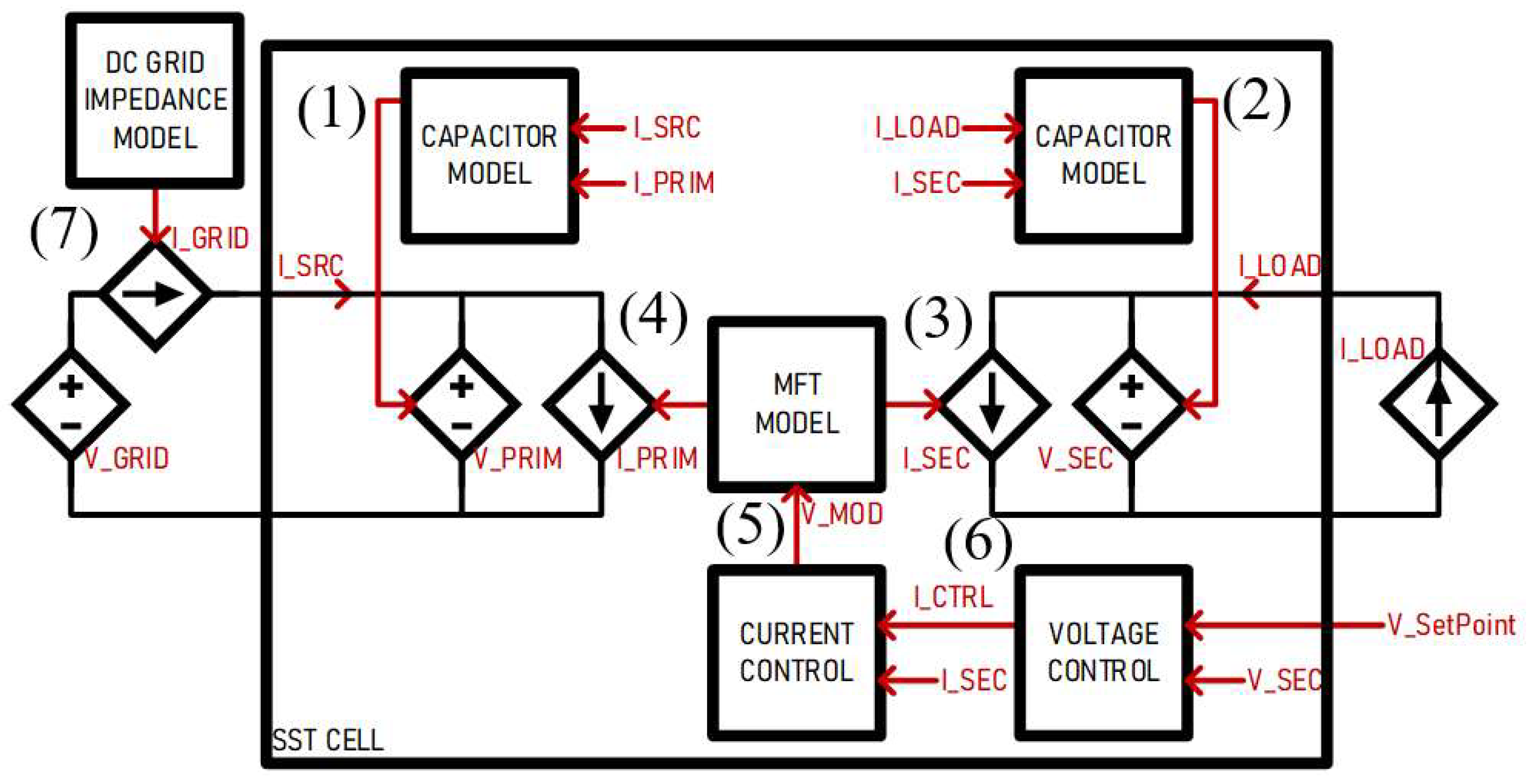
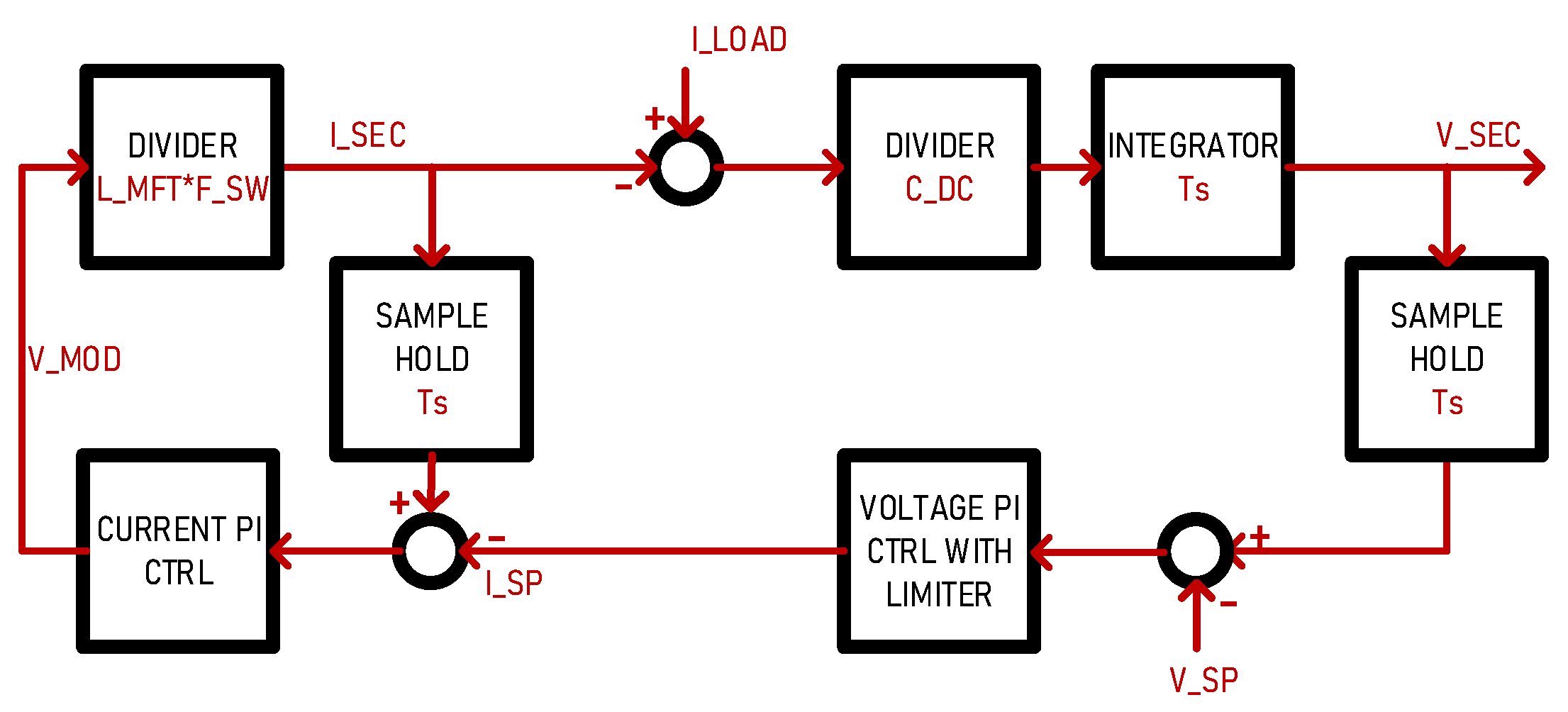
2.1. SST Elementary Cell

The SST cell is modelled with its equivalent current/voltage source model and can interface power systems that are also modelled as such. Both DC links on each side of the SST are interfaced with controlled voltage sources. The MFT windings are modelled with two controlled current sources which implement the physical aspects of an inductor. The functions performed by the SST cell are depicted in Figure 2.
As a convention adopted in this work, the SST is connected to a DC grid on its primary side and a current source load on its secondary side. The dynamics of the system are reflected in the various time constants of the system elements. The behaviour of the capacitors on each side of the SST is modelled as a current integrator multiplied by the capacitance value CDC, as described in Equations (1) and (2). The modulator has a time constant delay defined as a function of the switching frequency fSW. The current in the MFT inductance LMFT is modelled as an equivalent transfer function taking the applied voltage VMOD input as in (3) and (4).
The voltage/current cascaded PI controllers described by (5) and (6) are tuned and optimised as a function of the model’s physical parameters.
V P R I M = 1 C D C ( I S R C I P R I M )
V S E C = 1 C D C ( I L O A D I S E C )
I S E C = 1 L M F T F S W V M O D
I P R I M = I S E C N M F T
V M O D = K P I S E C I S P + K I ( I S E C I S P )
I S P = K P V S E C V S P + K I ( V S E C V S P )
I G R I D = 1 L G R I D ( V D C V G R I D R G R I D I G R I D )
The voltage controller maintains the secondary side voltage to a given set point, providing a current set point. The current controller maintains the MFT current to the given set points by providing the modulation voltage VMOD. The DC grid strength is modelled through its “equivalent impedance” represented by its resistive and inductive components RGRID and LGRID as in (7). The current source representing the grid impedance interfaces the DC ideal grid voltage source VDC with the primary side of the SST. The parameters used for running the model are described in Table 1.
The model is run at simulation time step ts = 1 µs, with current steps on the load side and a steady voltage on the grid side. A parameter sweep is performed on the PI controllers to assess its effect on the dynamics. Figure 3 shows that the dynamics of the SST cell model correspond, to a fair extent, to a real DAB-based SST converter. When compared to real hardware results from a built SST demonstrator as in [30], the voltage controller’s time responses correspond well enough to perform system-level studies. Another comparison is made between switching model and average model as in Figure 4, showing the dynamic accuracy and strong gain in computation time, as measured between a detailed switching model and the RMS average model, at the same simulation pace.
Figure 4 shows that the proposed average model for the SST cell is accurate enough when it comes to its behaviour, as seen from its DC terminals. The RMS values of the dynamic response, and the transferred power and the DV link variation to load steps is almost identical. A ratio of about 20 was measured in simulation speed, namely a few seconds against almost a minute for one SST.

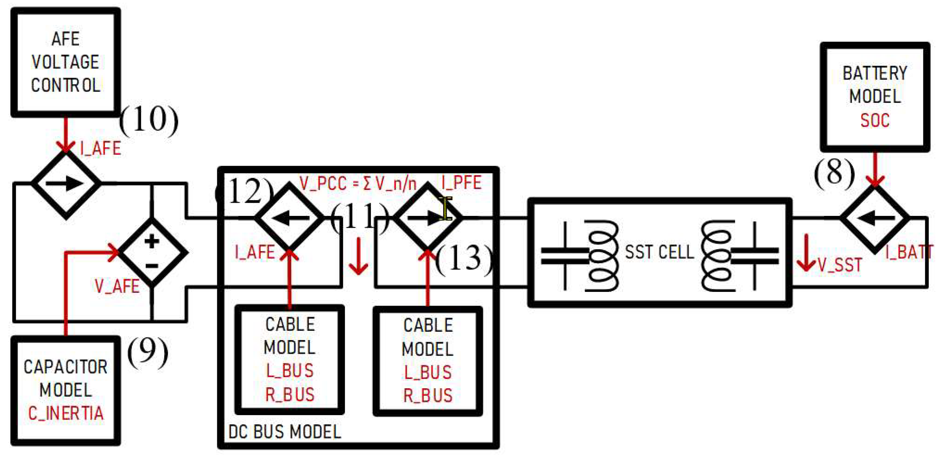
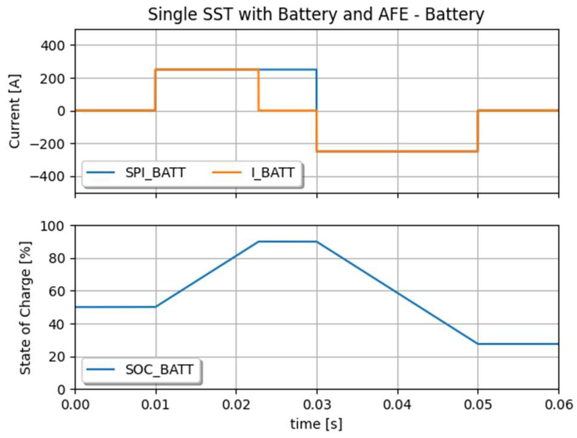
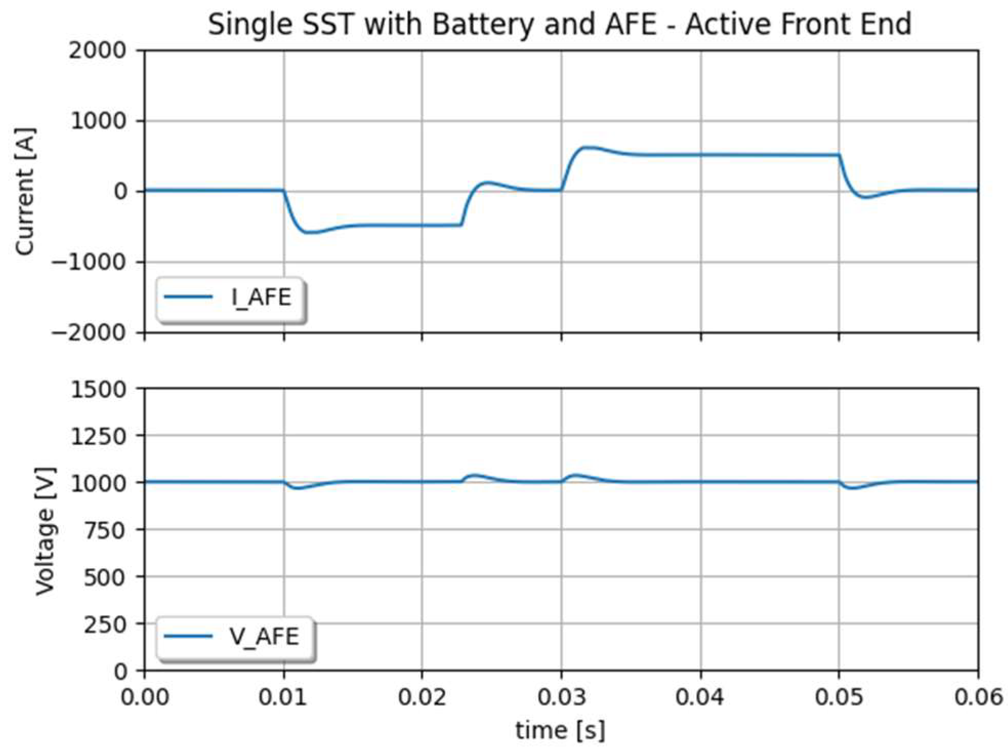
2.2. SST Cell Connecting a Battery and an AFE through a PCC

The same SST cell as described previously is run with a model of an active front end (AFE) on the primary side, and a model of a battery on the secondary side. As illustrated in Figure 5, a DC bus model is implemented for connecting the two voltage sources, from the AFE and the SST primary side. The DC bus model considers the AFE side as the side providing voltage, and the passive front end side (PFE) as the side only drawing current. The battery is a simple controlled current source; however, it produces a current only when its state of charge (SoC) permits it. SoC should typically vary between 10% and 90% to maintain optimal battery lifetime, it is calculated as a function of the integral of the battery current IBATT and the battery capacity QBATT as given in (8).
S o C = I B A T T Q B A T T
The AFE is modelled as a controlled current source IFEED connected to a controlled voltage source VAFE.
Equation (9) implements the behaviour of a capacitor model CAFE, which is the value that represents the inertia of the grid.
The AFE current is controlled in a way to maintain the AFE voltage to the voltage set point given by VDC with the use of a PI controller as given in (10). It features given dynamics, inertia, and current limitation set by the system.
V A F E = 1 C A F E ( I F E E D + I A F E )
I F E E D = K P V A F E V D C + K I V A F E V D C
The DC bus is connecting voltage sources and must be consequently modelled as current sources. The controls of those current sources implement the dynamic response of a cable with its resistance RDCBUS and line inductance LDCBUS. In this case, cables are sufficiently short, so as to not consider their capacitive component, as one would in DC transmission lines. This aspect will be the subject of a future work as the capacitive component has to be modelled as an equivalent voltage source, whose value is significantly impacted when far from the SST capacitors. The model features the voltage of the PCC, and current sharing between the connected devices. The voltage of the PCC is given by (11), while the currents IAFE and IPFE on both sides of the PCC are given by (12) and (13).
V P C C = V A F E + V P F E 2
I A F E = 1 L D C B U S ( V P C C V A F E R D C B U S I A F E )
I P F E = 1 L D C B U S ( V P C C V P F E R D C B U S I P F E )
Figure 6 shows the results of the model run with a load profile reflected by a current set point given to the battery system. When the SoC reaches 90%, the battery current falls to zero even though the set point is set to its nominal value. As illustrated in Figure 7, the AFE is maintaining the DC bus voltage with a “Synthetic Inertia” that is defined by its capacitor model and voltage controller.

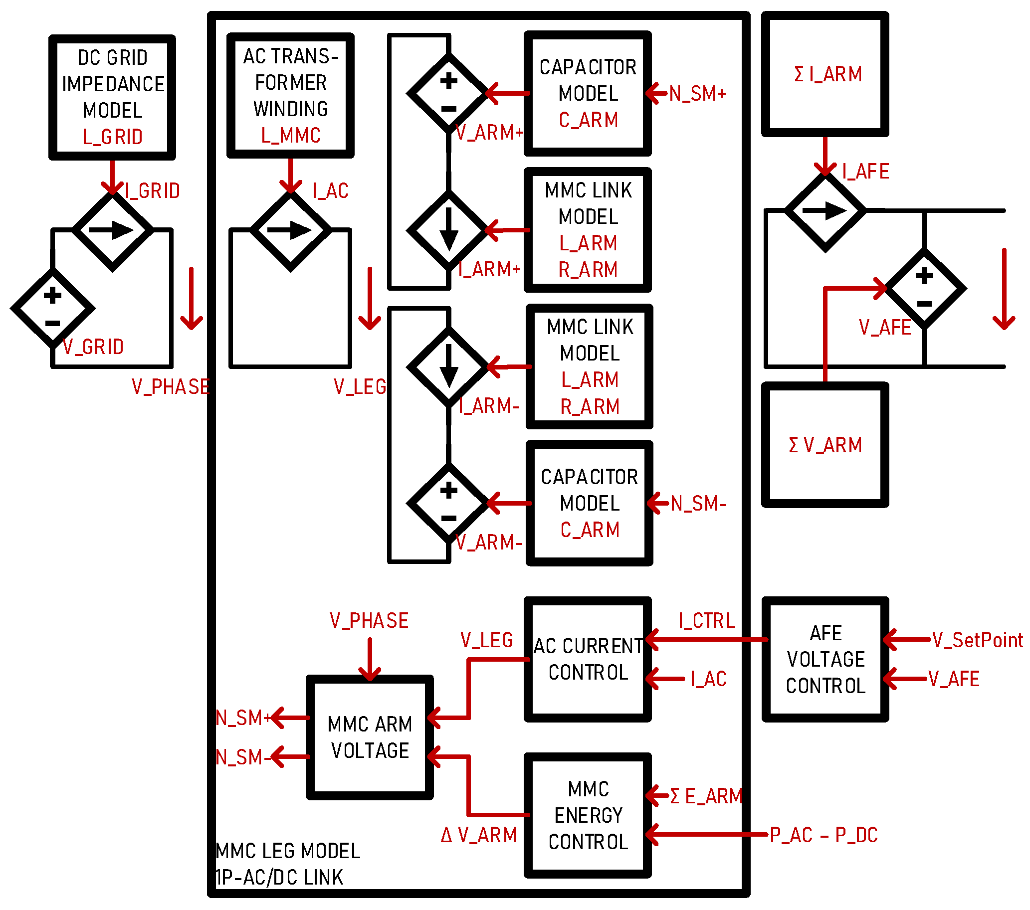
2.3. Considerations on Modelling MMC and AC Connection

The MMC block is modelled in a way where it can interface an AC port with a DC port. The AC port can be a three-phase grid transformer or an MFT connecting to another MMC leg for connecting to another DC grid. Each leg is running independently, connecting at the AC or DC port only. The MMC arms have capacitors, and their stored energy can be controlled [31]. When there is a power difference between the AC port and the DC port, the capacitors become charged or discharged, providing a so-called synthetic inertia.
As illustrated in Figure 8, the MMC arm is modelled as a voltage source that implements the insertion and bypass of capacitors in series with a current source, which implements the behaviours of the series-connected filter inductors. The AFE voltage controller and the energy controller both give set points of the sum and difference of arm voltages so they can provide two functions at a time, i.e., supply the DC grid voltage, and maintain the stored energy to the desired levels. On the AC side, the phases of the MMC connect in a way that reflects the AC transformer configuration, namely star, delta, or single phase. The capacitor’s effects on the waveforms are modelled in a way that their charge is a function of stored energy and arm current. A similar approach has been adopted in [32], aiming for real-time implementation.
This work focusses solely on the DC grid-related aspects and the impact of connecting numerous SSTs with symmetric and asymmetric loadings. All aspects related to the AC grid side, namely transformer connection and phase unbalances together and MMC energy storage, will be presented in a future study.

2.4. Discretisation in the Simulation Model and Stability

The equations given in this section are transposed to the simulator in terms of blocks, namely integrator, divider, sampler, and PI controller with or without limiter and anti-windup. Figure 9 shows an example for the computation of the secondary side capacitor voltage as seen at the SST port. The rest of the equations are implemented in the same fashion. In terms of the stability of the system and convergence of the computations, the time constants of the system must remain higher than the simulation time step of 1 µs. In other words, the inductors, capacitors, and controllers implemented in the system must be dimensioned accordingly.

3. Modelling of the Modular SST

The elementary SST cell described in section II.A can be vertically combined to generate modular configurations, such as input-parallel output-series (IPOS) and input-series output-parallel (ISOP), allowing it to connect LVDC to MVDC grids. Each SST cell is working independently and is implemented with bypass capabilities for simulating the effect of a cell fault on the system.

3.1. Parallel Connection in Modular SST

On the MVDC side, the series connection of voltage sources is not a problem. On the LVDC side, however, the parallel connection of voltage sources cannot be conducted without paying specific attention to the SST local PCC side. Voltage sources must be connected through an arrangement of controlled current sources that reflect the dynamics due to cabling resistance RDCBUS and coupling inductors LDCBUS. This allows for generating a PCC voltage that is equivalent to the mean value of all N primary side voltages of all N parallel connected SSTs as in (14); it also allows current sharing between the cells, reflecting on what is drawn from the load side, as given in (15). The final current share between the parallel connected modules is given by (16).
V P C C = V P R I M _ N N
I G R I D = I P R I M _ N
I S S T _ N = 1 L D C B U S ( V P C C V P R I M _ N R D C B U S I P R I M _ N )

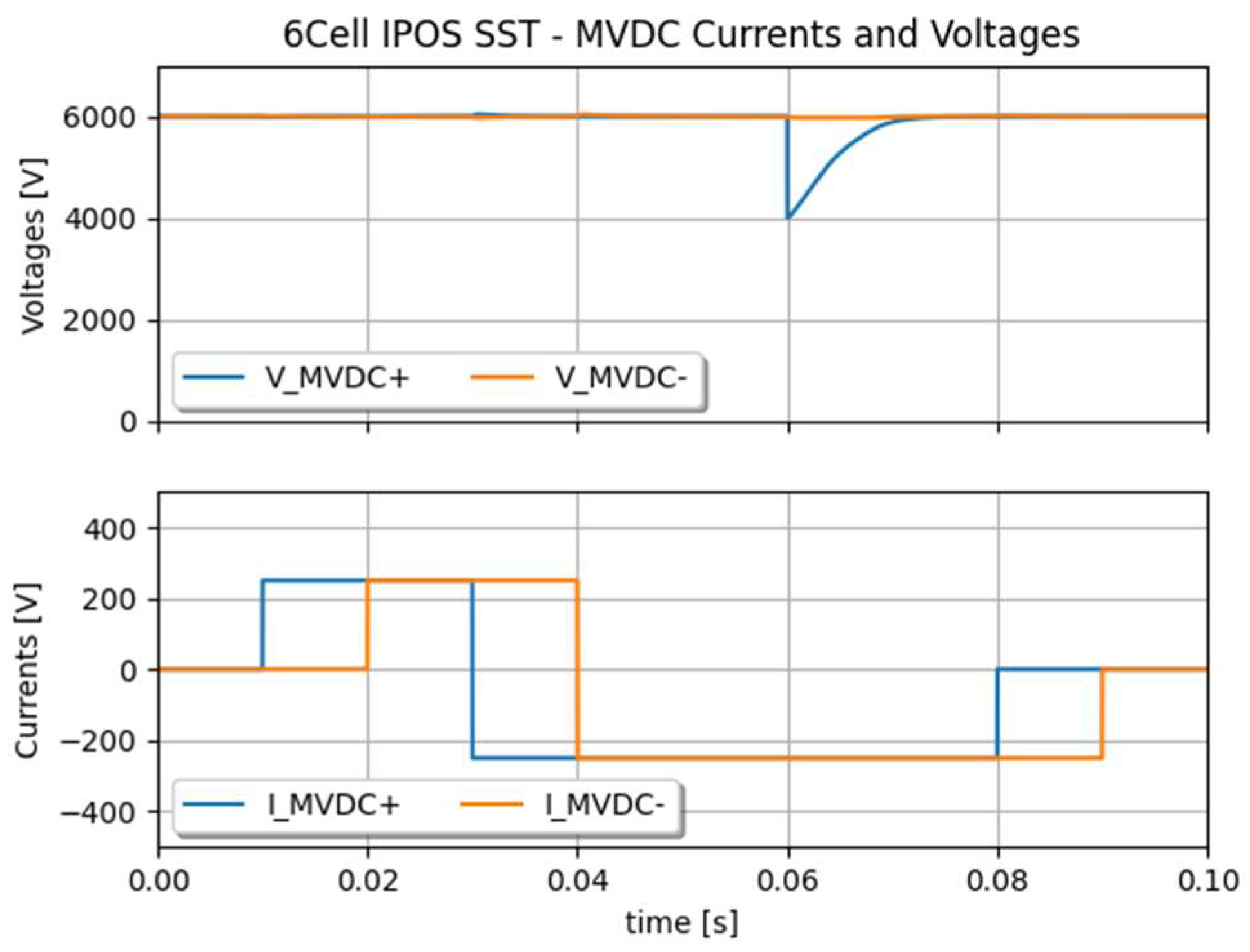
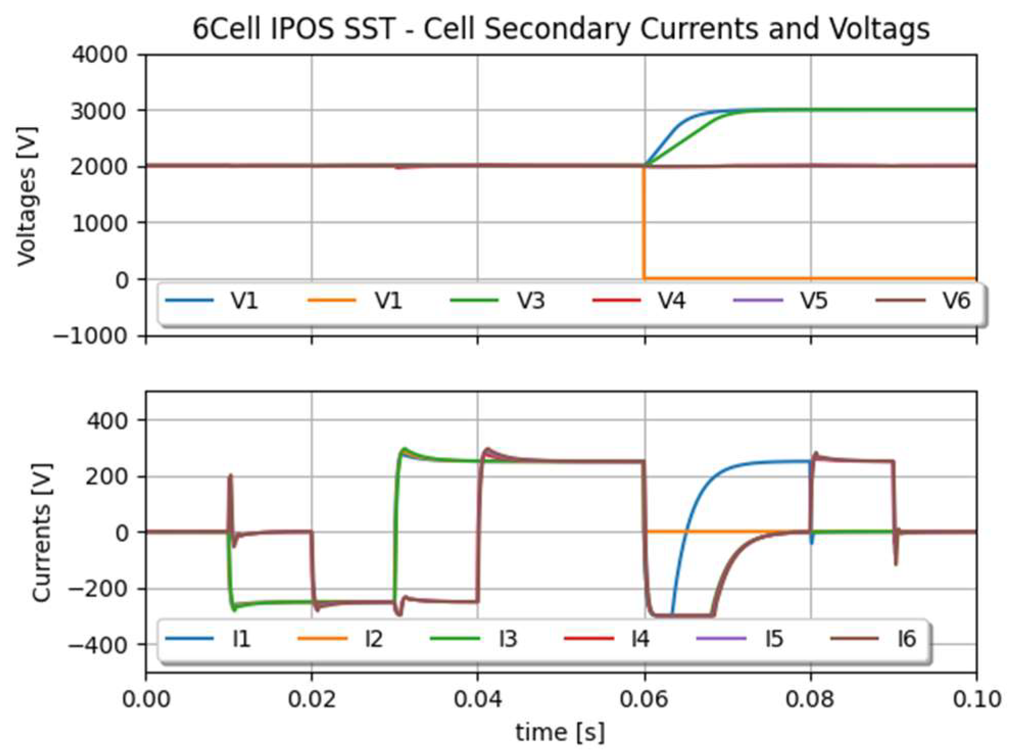
3.2. SST in IPOS Configuration with Faults

The 6-cell IPOS configuration illustrated in Figure 10 implements the equations given in (14)–(16).
The 3-port MVDC side voltage is fully controlled by the sum of individual SST cells. This arrangement allows asymmetric loading on the MVDC side with individual voltage control of both MVDC+ and MVDC- ports.
The system is run for demonstration with a fault occurring in one cell to assess the voltage and current stability on MVDC side.
Figure 11 shows the currents and voltages on the primary and secondary sides of the SST cells. Asymmetric currents are well distributed among the cells connected to the PCC. At some point, when the two MVDC side currents are opposite to each other, no current is taken from the LVDC grid side as the current is only circulating between the cell via the PCC. When a fault occurs, the MVDC+ voltage is maintained by two cells instead of three, as illustrated in Figure 12. Their voltage set point is re-adjusted by control after the fault occurrence. These results show the accuracy of the SST local PCC model for the parallel connection of individual SST cells.

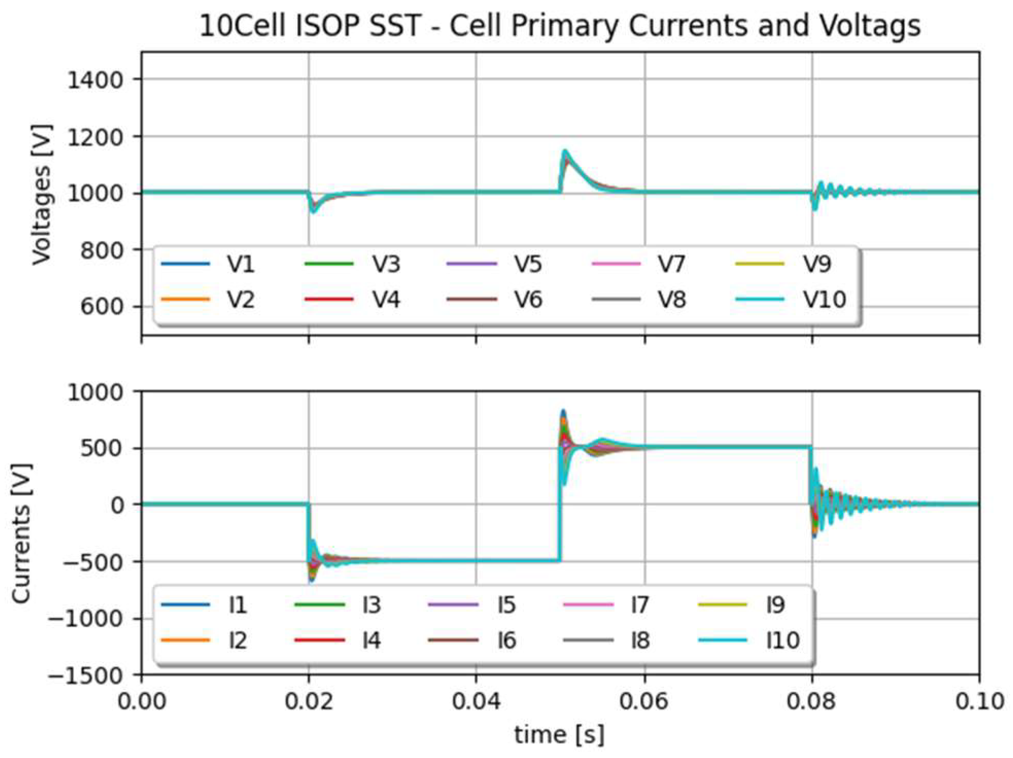
3.3. SST in ISOP Configuration

The ISOP is slightly different from IPOS in the sense that the MVDC side is given by the system and that the LVDC side must be controlled. In the arrangement presented by Figure 13, the LVDC side voltage is controlled by one SST cell, which provides a PCC for the full converter. All other cell voltages on the MVDC side are individually controlled, naturally providing voltage balancing between the cells.
The results depicted in Figure 14 show a slight voltage difference between the secondary side voltage of the SST cell that is controlling the LVDC side, because it takes the voltage difference between the MVDC and the sum of all secondary side cell voltages. Otherwise, we foresee excellent voltage and current balancing for this kind of arrangement.

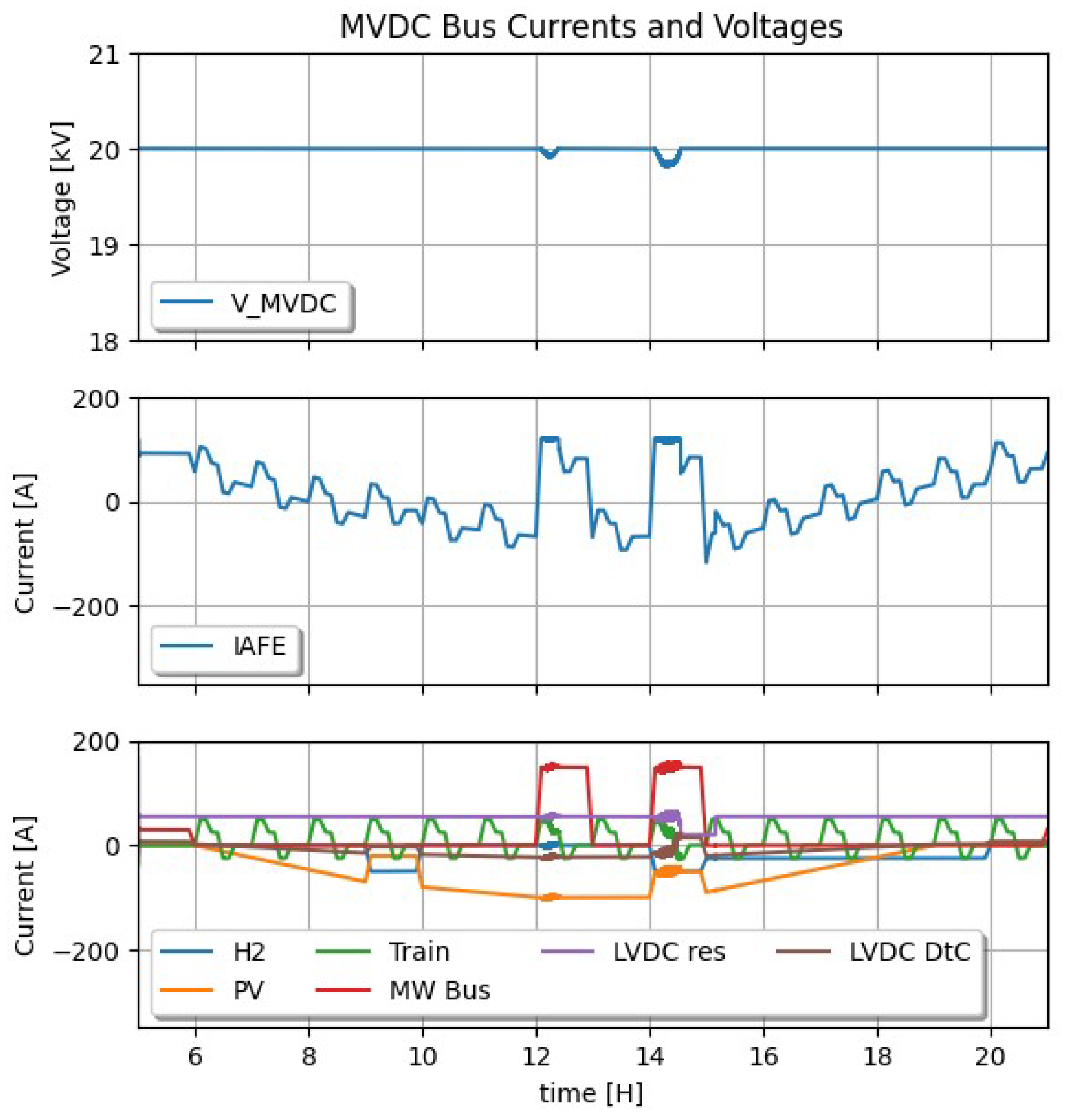
4. Simulation of the Full MVDC System

The previously presented models can be put together to build a complex MVCD system. The way of modelling illustrated in Figure 15 is quite independent from the simulation environment; in this case it has been implemented with Simba.io because of the Python API interface it features.

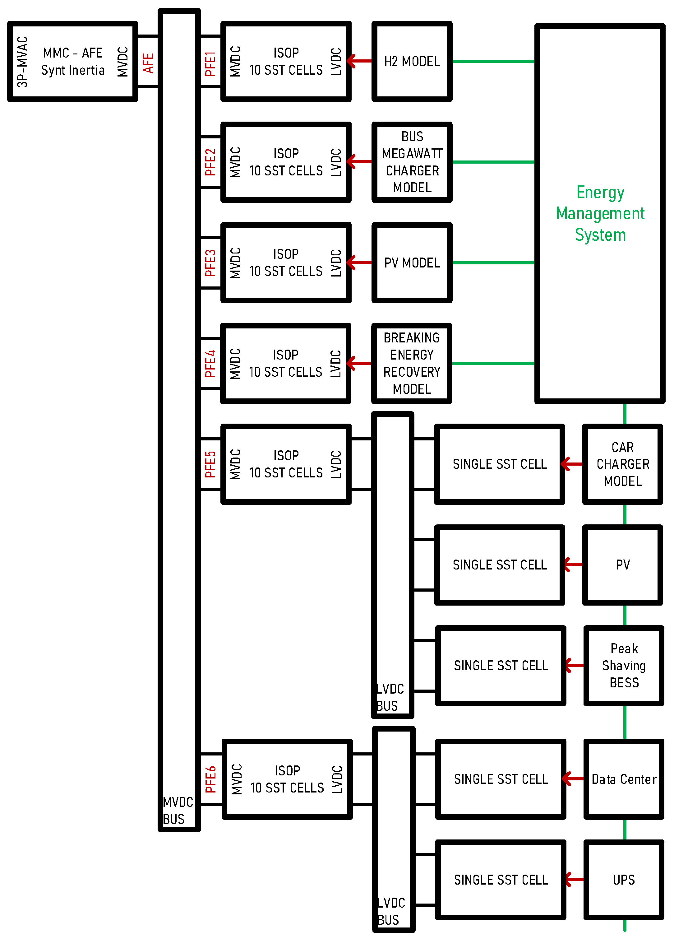
4.1. Full Power System Model

The power system in Figure 1 is entirely modelled and simulated with the elementary building blocks presented so far. As illustrated in Figure 15, an MVDC bus interfaces an AFE with several 10-cell ISOP blocks. The AFE maintains the voltage with a dynamic defined by its capacitive inertia and the voltage controller’s time constant. One of the 10-cell ISOP blocks interfaces with a LVDC bus where single SST blocks are connected for modelling bidirectional fast chargers for car batteries in a residential area with a PV and BESS for peak shaving. Another LVDC bus interfaces with a local data centre with UPS for maximum availability of data.
This model features 65 SSTs working together; the model took less than 30 min to simulate a 24 s simulation time with a simulation time step ts = 1 µs, with a quite standard computer, whereas a switching model would have taken about 10 h.
The simulated scenario is a full sunny day with some clouds involving PV energy drops supported by H2 fuel cells. Two e-mobility loads are connected, namely a bus megawatt charger and a train with breaking energy recovery. The 20 kV MMC AFE is limited to 120 A, requiring the microgrid to be intelligently managed to avoid voltage drops in the MVDC bus.
In Figure 16, a full typical day is depicted with regular trains and PV generation supported by H2 fuel cells. The scenario presents a case where megawatt charging is operated while a sudden drop of PV energy occurs. A small voltage drop is experienced on the MVDC side, saved by the local peak shaving and BESS storage on the LVDC side.
In Figure 17, the current load of the high-availability data centre (DtC) shows a continuous power supply with an action of the UPS responding to the possible voltage drop on the MVDC side (see Figure 16). Figure 18 represents a residential area, with a PV suppling to the main MVDC backbone. The scenario presents a car fast charge while the PV power drops. The small peak-shaving BESS enters but is not enough for covering the whole shortage; therefore, the drop is shown in Figure 16, and the UPS action in Figure 17.

4.2. Continuous Time Model Interface

The previously described system is run by a Python script called the Simba Python API. The system is run for a short period of time, typically a fraction of a second. The state of the system is returned and displayed in the graphic user interface, as illustrated in Figure 19.
From this collected state, an iterative process can be established: analysis is run for possible actions on the grid, new parameters are collected from the graphic user interface, a new run is initiated with the new states, and so on.
The continuous time simulation interface is a continuously run model on which actions can be performed. Those actions are either manually performed from the graphic user interface, or from Python-based automated algorithms.

5. Discussion

This study introduces a tool for analysing MVDC microgrids with high accuracy in system dynamics. This modelling approach reduces simulation effort by a factor of 20 compared to a switching model. However, the main focus is on the tool’s capabilities for simulation. It allows the implementation of Python-based power management that continuously interacts with the model. By using equivalent voltage/current sources, a complex MVDC system can be run quickly with realistic accuracy, independent of its simulation environment.
The MVDC system model was implemented in Powersys’ Simba environment due to its Python API. This setup enabled running the model from a continuously operating Python script with a dedicated graphical user interface. This approach, called “Continuous Time Simulation”, allows manual interaction with the system or algorithmic analysis and system-level management testing. This feature is significant because, with an available library or API, it is possible to envision complex algorithmic grid management systems, including modern DM- or AI-based systems, and quickly simulate them in a realistic grid model.
With the proposed modelling approach, complex systems can also be run for testing or educational purposes. Further work will include AC aspects related to the MMC-AFE such as phase unbalance and transformer connections. Also, DC transmission cable models may be added with their capacitive components. On the control side, some data mining or an AI approach could be studied with the use of available Python libraries.

Author Contributions

Conceptualisation, D.S. and M.C.; methodology, D.S. and M.C.; software, D.S.; validation, D.S. and M.C.; formal analysis, D.S. and M.C.; investigation, D.S. and M.C.; resources, M.C.; data curation, D.S.; writing—original draft preparation, D.S.; writing—review and editing, D.S. and M.C.; visualisation, D.S.; supervision, D.S. and M.C. All authors have read and agreed to the published version of the manuscript.

Funding

This research received no external funding.

Data Availability Statement

Data is contained within the article.

Acknowledgments

Contributions of T. Umuhire and M. Félix in the frame of their Bachelor thesis at HEIG-VD, under the supervision of the authors. The authors would also like to acknowledge the contributions of E. Rutovic and G. Fontés from Aesim-Simba for their technical expertise and contribution to the modelling and Python interfaces.

Conflicts of Interest

Author Daniel Siemaszko was employed by the company Hitachi Energy Ltd. The remaining authors declare that the research was conducted in the absence of any commercial or financial relationships that could be construed as a potential conflict of interest.

Nomenclature

AIArtificial Intelligence
AFEActive Front End
DABDual Active Bridge
DMData Mining
EVElectric Vehicle
HMGConventional hybrid AC–DC microgrid
ISOPInput Series Output Parallel
MHMMeshed Hybrid Microgrid
MMCModular Multilevel Convert
LVDLow-Voltage DC
MFTMedium-Frequency Transformer
MMModular Multilevel Converter
MVDCMedium-Voltage DC
PETPower Electronics Transformer
PFEPassive Front End
PPCPoint of Common Coupling
REGRenewable Energy Generation
SoCState of Charge (battery related)
SSTSolid-State Transformer
STSmart Transformer
UPSUninterrupted Power Supply

References

  1. Li, W.; Li, Y.; Yu, S.; Wei, T.; Chen, J.; Liu, Y.; Xu, S. State of the Art of Researches and Applications of MVDC Distribution Systems in Power Grid. In Proceedings of the IECON 2019—45th Annual Conference of the IEEE Industrial Electronics Society, Lisbon, Portugal, 14–17 October 2019; pp. 5680–5685. [Google Scholar] [CrossRef]
  2. Núñez-Rodríguez, R.A.; Unsihuay-Vila, C.; Posada, J.; Pinzón-Ardila, O.; Aoki, A.R.; Bueno-Otto, R. Real-Time Testing Optimal Power Flow in Smart-Transformer-Based Meshed Hybrid Microgrids: Design and Validation. Energies 2024, 17, 1950. [Google Scholar] [CrossRef]
  3. Das, D.; Kumar, C. Partial Startup Scheme for Smart Transformer in Meshed Hybrid Islanded Grid Operation. IEEE Trans. Ind. Appl. 2022, 58, 142–151. [Google Scholar] [CrossRef]
  4. Hrishikesan, V.M.; Kumar, C.; Liserre, M. An MVDC-Based Meshed Hybrid Microgrid Enabled Using Smart Transformers. IEEE Trans. Ind. Electron. 2022, 69, 3722–3731. [Google Scholar] [CrossRef]
  5. Zhao, X.; Li, B.; Fu, Q.; Mao, S.; Xu, D.G.; Leon, J.I.; Franquelo, L.G. DC Solid State Transformer Based on Three-Level Power Module for Interconnecting MV and LV DC Distribution Systems. IEEE Trans. Power Electron. 2021, 36, 1563–1577. [Google Scholar] [CrossRef]
  6. Jin, H.; Chen, W.; Hou, K.; Shao, S.; Shu, L.; Li, R. A Sharing-Branch Modular Multilevel DC Transformer with Wide Voltage Range Regulation for DC Distribution Grids. IEEE Trans. Power Electron. 2021, 37, 5714–5730. [Google Scholar] [CrossRef]
  7. Zhuang, Y.; Liu, F.; Huang, Y.; Wang, S.; Pan, S.; Zha, X.; Diao, X. A Multiport DC Solid-state Transformer for MVDC Integration Interface of Multiple Distributed Energy Sources and DC Loads in Distribution Network. IEEE Trans. Power Electron. 2022, 37, 2283–2296. [Google Scholar] [CrossRef]
  8. Sha, G.; Duan, Q.; Sheng, W.; Ma, C.; Zhao, C.; Zhang, Y.; Tian, J. Research on Multi-Port DC-DC Converter Based on Modular Multilevel Converter and Cascaded H Bridges for MVDC Applications. IEEE Access 2021, 9, 95006–95022. [Google Scholar] [CrossRef]
  9. Zhao, S.; Chen, Y.; Cui, S.; Hu, J. Modular Multilevel DC-DC Converter with Inherent Bipolar Operation Capability for Resilient Bipolar MVDC Grids. CPSS Trans. Power Electron. Appl. 2022, 7, 37–48. [Google Scholar] [CrossRef]
  10. Zhang, J.; Zhang, Y.; Zhou, J.; Wang, J.; Shi, G.; Cai, X. Control of a Hybrid Modular Solid-State Transformer for Uninterrupted Power Supply Under MVdc Short-Circuit Fault. IEEE Trans. Ind. Electron. 2023, 70, 76–87. [Google Scholar] [CrossRef]
  11. Sadat, A.R.; Krishnamoorthy, H.S. Fault-Tolerant ISOSP Solid-State Transformer for MVDC Distribution. IEEE J. Emerg. Sel. Top. Power Electron. 2021, 9, 6985–6996. [Google Scholar] [CrossRef]
  12. Liao, J.; Zhou, N.; Qin, Z.; Purgat, P.; Wang, Q.; Bauer, P. Coordination Control of Power Flow Controller and Hybrid DC Circuit Breaker in MVDC Distribution Networks. J. Mod. Power Syst. Clean Energy 2021, 9, 1257–1268. [Google Scholar] [CrossRef]
  13. Wang, Y.; Li, Q.; Li, B.; Wei, T.; Zhu, Z.; Li, W.; Wen, W.; Wang, C. A Practical DC Fault Ride-Through Method for MMC Based MVDC Distribution Systems. IEEE Trans. Power Deliv. 2021, 36, 2510–2519. [Google Scholar] [CrossRef]
  14. Feng, X.; Xiong, Q.; Gattozzi, A.L.; Hebner, R.E. Partial Discharge Experimental Study for Medium Voltage DC Cables. IEEE Trans. Power Deliv. 2021, 36, 1128–1136. [Google Scholar] [CrossRef]
  15. Hunter, L.C.; Booth, C.D.; Egea-Alvarez, A.; Dysko, A.; Finney, S.J.; Junyent-Ferre, A. A New Fast-Acting Backup Protection Strategy for Embedded MVDC Links in Future Distribution Networks. IEEE Trans. Power Deliv. 2021, 36, 861–869. [Google Scholar] [CrossRef]
  16. Zhang, G.; Song, J.; Li, C.; Gu, X. A Circulating Current Suppression Strategy for MMC Based on the 2N+1 PWM Approach. World Electr. Veh. J. 2023, 14, 106. [Google Scholar] [CrossRef]
  17. Pesce, C.; Riedemann, J.; Peña, R.; Andrade, I.; Jara, W.; Villalobos, R. Decoupled Control for Double-T Dc-Dc MMC Topology for MT-HVdc/MVdc Grids. Appl. Sci. 2023, 13, 3778. [Google Scholar] [CrossRef]
  18. Liao, Z.; Jiao, Y.; Suo, Z.; Li, B.; Zhao, X.; Han, L.; Xu, D. A Three-Port Power Electronic Transformer Based on Magnetic Integration. Appl. Sci. 2022, 12, 11607. [Google Scholar] [CrossRef]
  19. Lin, Y.; Fu, L. A Study for a Hybrid Wind-Solar-Battery System for Hydrogen Production in an Islanded MVDC Network. IEEE Access 2022, 10, 85355–85367. [Google Scholar] [CrossRef]
  20. Robertson, J.; Harrison, G.; Wallace, A. A pseudo-real time distribution network simulator for analysis of coordinated ANM control strategies. In Proceedings of the CIRED 2012 Workshop: Integration of Renewables into the Distribution Grid, Lisbon, Portugal, 29–30 May 2012; pp. 1–4. [Google Scholar] [CrossRef]
  21. Lo, B.; Monti, A.; Dougal, R. Real-time hardware-in-the-loop testing during design of power electronics controls. In Proceedings of the IECON’03, 29th Annual Conference of the IEEE Industrial Electronics Society (IEEE Cat. No.03CH37468), Roanoke, VA, USA, 2–6 November 2003; Volume 2, pp. 1840–1845. [Google Scholar] [CrossRef]
  22. Kiffe, A.; Formann, S.; Schulte, T.; Maas, J. Hardware-in-the-loop capable state-space-averaging models for power converters in discontinuous conduction mode considering parasitic component behavior. In Proceedings of the 2011 14th European Conference on Power Electronics and Applications, Birmingham, UK, 30 August–1 September 2011; pp. 1–10. [Google Scholar]
  23. Nayak, G.; Dasgupta, A. Full Order Averaged Modelling for Modular Solid State Transformer. In Proceedings of the 2020 IEEE International Conference on Power Electronics, Drives and Energy Systems (PEDES), Jaipur, India, 16–19 December 2020; pp. 1–6. [Google Scholar] [CrossRef]
  24. Yang, J.; Buticchi, G.; Yan, H.; Gu, C.; Zhang, H.; Wheeler, P. Impedance-based Sensitivity Analysis of Dual Active Bridge DC-DC Converter. In Proceedings of the 2019 IEEE 13th International Conference on Compatibility, Power Electronics and Power Engineering (CPE-POWERENG), Sonderborg, Denmark, 23–25 April 2019; pp. 1–5. [Google Scholar] [CrossRef]
  25. Rosyadi, M.; Umemura, A.; Takahashi, R.; Tamura, J. Detailed and Average Models of a Grid-Connected MMC-Controlled Permanent Magnet Wind Turbine Generator. Appl. Sci. 2022, 12, 1619. [Google Scholar] [CrossRef]
  26. Siemaszko, D.; Noisette, P. Power System Simulation Tool for Quick Benchmarking of Innovative MVDC Grids in E-Mobility Applications. In Proceedings of the 2022 24th European Conference on Power Electronics and Applications (EPE’22 ECCE Europe), Hanover, Germany, 5–9 September 2022. [Google Scholar]
  27. Stieneker, M.; De Doncker, R.W. Dual-Active Bridge DC-DC Converter Ssystems for Medium-Voltage DC Distribution Grids. In Proceedings of the Power Electronics Conference 2015, COBEP 2015, Fortaleza, Brazil, 29 November–2 December 2015. [Google Scholar]
  28. Barrade, P. Électronique de Puissance; Presses Polytechniques et Universitaires Romandes: Lausanne, Switzerland, 2006. [Google Scholar]
  29. Available online: https://simba.io/ (accessed on 3 March 2024).
  30. Heinig, S.; Siemaszko, D.; Baumann, R.; Hubatka, N.; Klaeusler, M.; Ruiz, R.; Burkart, R.; Yuan, C. Experimental Insights into the MW Range Dual Active Bridge with Silicon Carbide Devices. In Proceedings of the International Power Electronics Conference IPEC-Himeji 2022—ECCE ASIA, Himeji, Japan, 15–19 May 2022. [Google Scholar]
  31. Angquist, L.; Antonopoulos, A.; Siemaszko, D.; Ilves, K.; Vasiladiotis, M.; Nee, H.-P. Open-Loop Control of Modular Multilevel Converters Using Estimation of Stored Energy. IEEE Trans. Ind. Appl. 2011, 47, 2516–2524. [Google Scholar] [CrossRef]
  32. Milovanovic, S.; Luo, M.; Dujic, D. Virtual Capacitor Concept for Computationally Efficient and Flexible Real-Time MMC Model. IEEE Access 2021, 9, 144211–144226. [Google Scholar] [CrossRef]
Figure 1. Simulated power system including MMC active front end and SSTs, represented by multiple isolated DC/DC converters.
Electronics 13 02193 g001
Figure 2. System-level model of the SST.
Electronics 13 02193 g002
Figure 3. SST cell model dynamics run with various integral gains.
Electronics 13 02193 g003
Figure 4. Dynamic performance and accuracy comparison between switching model and RMS average model of the SST model.
Electronics 13 02193 g004
Figure 5. SST cell model connecting a battery to an AFE through a DC PCC.
Electronics 13 02193 g005
Figure 6. State of charge of the battery connected to the SST.
Electronics 13 02193 g006
Figure 7. Active front end with synthetic inertia and equivalent grid strength.
Electronics 13 02193 g007
Figure 8. Model of the MMC based AFE control, focus on the DC side.
Electronics 13 02193 g008
Figure 9. System sampling and control implementation—SST case.
Electronics 13 02193 g009
Figure 10. IPOS configuration of six SSTs.
Electronics 13 02193 g010
Figure 11. IPOS configuration of six SSTs—asymmetric loading from MVDC.
Electronics 13 02193 g011
Figure 12. IPOS configuration of six SSTs—current sharing on the secondary side.
Electronics 13 02193 g012
Figure 13. ISOP configuration of 10 SSTs.
Electronics 13 02193 g013
Figure 14. ISOP configuration of 10 SSTs—current sharing on primary side.
Electronics 13 02193 g014
Figure 15. Simulated power system including MMC active front end and SSTs.
Electronics 13 02193 g015
Figure 16. Current load on the active front end supplying the microgrid.
Electronics 13 02193 g016
Figure 17. Current load on the MVDC/LVDC converter supplying the DC Data Center.
Electronics 13 02193 g017
Figure 18. Current load on the MVDC/LVDC converter supplying the residential area.
Electronics 13 02193 g018
Figure 19. Functioning of the continuous time simulation interface.
Electronics 13 02193 g019
Table 1. List of considered SST cell parameters.
SymbolValueComment
DC nominal voltage on primary sideVPRIM1000 VSet by grid model VGRID
DC nominal voltage on secondary sideVSEC2000 VControlled by SST
nominal current on secondary sideISEC250 ASet by load model ILOAD
maximum current on secondary sideISEC_MAX300 AControlled by SST
MFT-side SST inductanceLMFT8.5 µHDefines control’s time response
DC-side SST capacitorCDC3 mFDefines control’s time response
MFT switching frequencyfSW10 kHzDefines control’s transfer function
Simulation time stepts1 µsThis time step is used in all runs
Disclaimer/Publisher’s Note: The statements, opinions and data contained in all publications are solely those of the individual author(s) and contributor(s) and not of MDPI and/or the editor(s). MDPI and/or the editor(s) disclaim responsibility for any injury to people or property resulting from any ideas, methods, instructions or products referred to in the content.

