Article

An Advanced Approach to Object Detection and Tracking in Robotics and Autonomous Vehicles Using YOLOv8 and LiDAR Data Fusion

Robotics Department, Yeungnam University, Gyeongsan 38541, Republic of Korea
*
Author to whom correspondence should be addressed.
Electronics 2024, 13(12), 2250; https://doi.org/10.3390/electronics13122250
Submission received: 24 May 2024 / Revised: 1 June 2024 / Accepted: 6 June 2024 / Published: 7 June 2024

Abstract

:
Accurately and reliably perceiving the environment is a major challenge in autonomous driving and robotics research. Traditional vision-based methods often suffer from varying lighting conditions, occlusions, and complex environments. This paper addresses these challenges by combining a deep learning-based object detection algorithm, YOLOv8, with LiDAR data fusion technology. The principle of this combination is to merge the advantages of these technologies: YOLOv8 excels in real-time object detection and classification through RGB images, while LiDAR provides accurate distance measurement and 3D spatial information, regardless of lighting conditions. The integration aims to apply the high accuracy and robustness of YOLOv8 in identifying and classifying objects, as well as the depth data provided by LiDAR. This combination enhances the overall environmental perception, which is critical for the reliability and safety of autonomous systems. However, this fusion brings some research challenges, including data calibration between different sensors, filtering ground points from LiDAR point clouds, and managing the computational complexity of processing large datasets. This paper presents a comprehensive approach to address these challenges. Firstly, a simple algorithm is introduced to filter out ground points from LiDAR point clouds, which are essential for accurate object detection, by setting different threshold heights based on the terrain. Secondly, YOLOv8, trained on a customized dataset, is utilized for object detection in images, generating 2D bounding boxes around detected objects. Thirdly, a calibration algorithm is developed to transform 3D LiDAR coordinates to image pixel coordinates, which are vital for correlating LiDAR data with image-based object detection results. Fourthly, a method for clustering different objects based on the fused data is proposed, followed by an object tracking algorithm to compute the 3D poses of objects and their relative distances from a robot. The Agilex Scout Mini robot, equipped with Velodyne 16-channel LiDAR and an Intel D435 camera, is employed for data collection and experimentation. Finally, the experimental results validate the effectiveness of the proposed algorithms and methods.

1. Introduction

Object detection and tracking are important concepts in robotics [1,2,3] and self-driving [4,5]. There are several applications of object detection and tracking, such as in robotics for obstacle detection [5,6], in retail for tracking customer movement [7], in sports for analyzing player movements [8], and in security systems for monitoring and surveillance [9]. Object detection and tracking are important components in the fields of robotics and self-driving vehicles. In robotics, object detection helps robots to understand their environment better. It helps robots build more accurate maps and effectively avoid obstacles and other robots. For self-driving vehicles, detecting and tracking objects, like other vehicles, pedestrians, road barriers, road signs, traffic lights, and lane marking, helps self-driving vehicles understand their surroundings, make decisions, and navigate safely and correctly. In addition, object detection and tracking can help the robots or self-driving vehicles gather amounts of data, which can be used for optimizing paths, improving algorithms and models, and enhancing the safety and efficiency of autonomous driving systems. Computational intelligence techniques [10,11], particularly those involving machine learning and deep learning, play a significant role in these systems.
Current object detection and tracking approaches have the challenges of speed, accuracy, and reliability, particularly in dynamic and complex environments [12,13]. Addressing these challenges is essential for advancing autonomous technology. This paper proposes an integrated approach that combines LiDAR and camera data to achieve a comprehensive understanding of the environment, enhancing object localization and mapping. By leveraging the speed and accuracy of YOLOv8 alongside the precise spatial analysis capabilities of LiDAR, the proposed system aims to improve detection and tracking performance, meeting the demands of real-time applications. Maintaining the identity of objects in motion, despite changes in appearance or partial occlusion, remains a significant challenge [14,15,16]. This paper introduces a 3D tracking algorithm designed to calculate the 3D poses of objects, ensuring robust detection and tracking even when objects are partially occluded or missing parts. Enhanced tracking methods aim to improve the robustness and reliability of tracking systems, ensuring consistent object identification.
Combining LiDAR and camera data to achieve object detection and tracking requires several technologies: LiDAR data processing, object detection based on camera data, LiDAR and camera data calibration and fusion, and object tracking.
LiDAR point cloud data consist of millions of points that map the surroundings in three dimensions, providing a detailed view beyond 2D images or videos. This is critical for accurately identifying and distinguishing objects in a scene. LiDAR provides precise distance measurements, and being able to accurately determine the position, size, and shape of objects is critical for applications such as autonomous driving, where understanding the spatial arrangement of objects is crucial. LiDAR performs well in different lighting and weather conditions, such as low light, fog, or rain. This robustness enables LiDAR to reliably detect and track objects in a variety of environments. Point cloud data generated in real time can be analyzed and responded to instantly. This is important for applications that require fast decision making, such as collision avoidance systems in self-driving cars; moreover, these are significant in LiDAR point cloud data for object detection and tracking. LiDAR ground thresholding [17,18] is an important step in processing LiDAR point cloud data, especially for applications like navigation and mapping. The goal is to separate ground points from non-ground points. In this paper, we propose a simple ground thresholding algorithm to quickly segment the ground points and non-ground points. In the algorithm, a threshold height is used to determine whether a LiDAR point is classified as a ground point or a non-ground point. The challenge is to select the correct threshold height for effective ground point segmentation. In this paper, to solve this problem, three conditions are considered to determine the threshold height: flat terrain, uphill terrain, and downhill terrain.
The object detection process involves identifying objects within a single image or frame. It includes recognizing the object’s type and drawing a bounding box or similar marker around the object to highlight its location in the image. The techniques for object detection include YOLO (You Only Look Once) [19], SSD (Single Shot MultiBox Detector) [20], and Faster R-CNN [21]. YOLO system is highly efficient and has revolutionized the field of computer vision due to its speed and accuracy. Unlike traditional object detection systems that first propose regions and then classify each region separately, YOLO applies a single neural network to the full image. This network divides the image into regions and predicts bounding boxes and probabilities for each region simultaneously. YOLO’s unique approach allows it to perform detection at a much faster rate compared to other methods. This makes it particularly suitable for real-time applications, such as video surveillance, self-driving cars, and robotics. YOLO also achieves high accuracy in detecting objects, although it may not be as precise as some slower, region-proposal-based methods. It balances speed and accuracy effectively, making it a popular choice in many practical applications. Compared with earlier YOLO versions [22,23,24], YOLOv8 is faster, more accurate, and more flexible [25,26]. These advantages make YOLOv8 particularly suitable for fusion with LiDAR data, providing a powerful solution for real-time object detection and tracking in complex dynamic environments. This fusion solves the key challenges faced by current object detection and tracking systems and improves overall performance and reliability.
The extrinsic calibration between a LiDAR sensor and a camera is a crucial step in integrating data from both sensors for applications in computer vision and mobile robotics [27,28]. LiDAR sensors provide depth information by measuring the time it takes for laser pulses to return after hitting an object. On the other hand, cameras capture color and texture information. By combining these two sources of data, a more comprehensive understanding of the environment can be achieved. This fusion is especially powerful in tasks like object recognition and navigation. The fusion of LiDAR and camera data enables more accurate localization of objects in the environment. While LiDAR provides precise distance measurements, cameras contribute additional information about the appearance of objects. There are two parts of calibration, intrinsic calibration and extrinsic calibration. For the camera, intrinsic calibration estimates the intrinsic parameters such as focal length, skew, and image center. This is often carried out using calibration patterns or dedicated calibration procedures. LiDAR sensors usually do not have intrinsic parameters like cameras, but checking for any potential distortions or biases in the LiDAR data is essential. Extrinsic calibration estimates the rigid body transformation between the LiDAR and the camera [29]. Extrinsic calibration ensures that data from the LiDAR and the camera are aligned correctly in a shared coordinate system. In autonomous vehicles and robotic systems, extrinsic calibration is essential for tasks like obstacle avoidance, path planning, and navigation. In this paper, a simple LiDAR and camera fusion process is proposed to translate the coordinates of objects detected by LiDAR into the coordinate system of the camera image.
Once objects are detected, the object tracking process involves following the objects and calculating the pose of the object in a video. The challenge in object tracking is to maintain the identity of the object even when it moves, changes in appearance, or is partially obscured. For object tracking, Kalman Filter [30], Mean-shift [31], and tracking-by-detection approaches are used. This paper describes an advanced approach for object detection and tracking, integrating YOLOv8 for image-based object detection with LiDAR data for precise spatial analysis. According to the object detection result and LiDAR points calibration result, a method is proposed for LiDAR points segmentation to cluster different objects. Then, the object tracking algorithm is proposed to calculate the object’s 3D poses and to calculate the relative distance between the robot and the object.

2. Related Works

The related work of object detection and tracking is as in [12,32,33]. Ref. [10] introduced an approach to object detection and tracking based on YOLO and Kalman Filter algorithms. However, the approach lacks two sensors’ calibration processes and it does not provide the 3D poses of the object. Ref. [32] focuses on fusing the LiDAR and camera to achieve better detection performance. However, there is no LiDAR data segment process to increase efficiency. The authors ignored the object tracking issue. Object detection and tracking are critical and interrelated components in the fields of robotics and autonomous vehicles. Ref. [33] improves the object detection performance by designing a feature switch layer, based on camera–lidar fusion. However, it did not apply the method for 3D object detection.
The related work of ground thresholding is as in [34,35]. Ref. [34] proposes a Jump–Convolution Process (JCP) to convert the 3D point cloud segmentation problem into a 2D image smoothing problem. The method improves segmentation accuracy and terrain adaptability while maintaining low time costs, making it suitable for real-time applications in autonomous vehicles. While the method is designed to be fast, it still requires significant computational resources, particularly for real-time applications. The convolution operations and the iterative nature of the jump process can be computationally intensive. The approach involves projecting 3D point cloud data onto a 2D image for processing. This projection can lead to a loss of spatial information and might result in inaccuracies. Ref. [35] uses PointNet and Pillar Feature Encoding to estimate ground plane elevation and segment ground points in real time. The accuracy of the 2D elevation maps used in GroundGrid depends on the resolution of the grid. High-resolution grids provide better detail but at the cost of increased computational load and memory usage. The approach might face scalability issues when applied to very large-scale point clouds or environments.
The contributions of this paper are as follows: (1) Compared with [34,35], this paper presents a simple ground thresholding algorithm to quickly segment ground points and non-ground points in LiDAR data. This algorithm considers different terrain conditions (flat, uphill, and downhill) to determine the correct threshold height, enhancing the efficiency and effectiveness of ground point segmentation. (2) A method for extrinsic calibration between LiDAR and camera data is proposed. This process ensures accurate alignment of data from both sensors in a shared coordinate system, which is essential for tasks such as obstacle avoidance, path planning, and navigation. (3) This paper proposes an advanced system that integrates YOLOv8 for image-based object detection with LiDAR data for precise spatial analysis. This integration applies YOLOv8’s speed and accuracy and LiDAR’s precise measurements to enhance object detection and tracking performance, meeting the demands of real-time applications. (4) A novel 3D tracking algorithm is introduced to calculate the 3D poses of objects. This algorithm ensures robust detection and tracking even when objects are partially occluded or missing parts. Compared with [10,32,33], the algorithms proposed in this paper help detect 3D objects and calculate 3D poses of objects.

3. Multiple Object Detection and Tracking

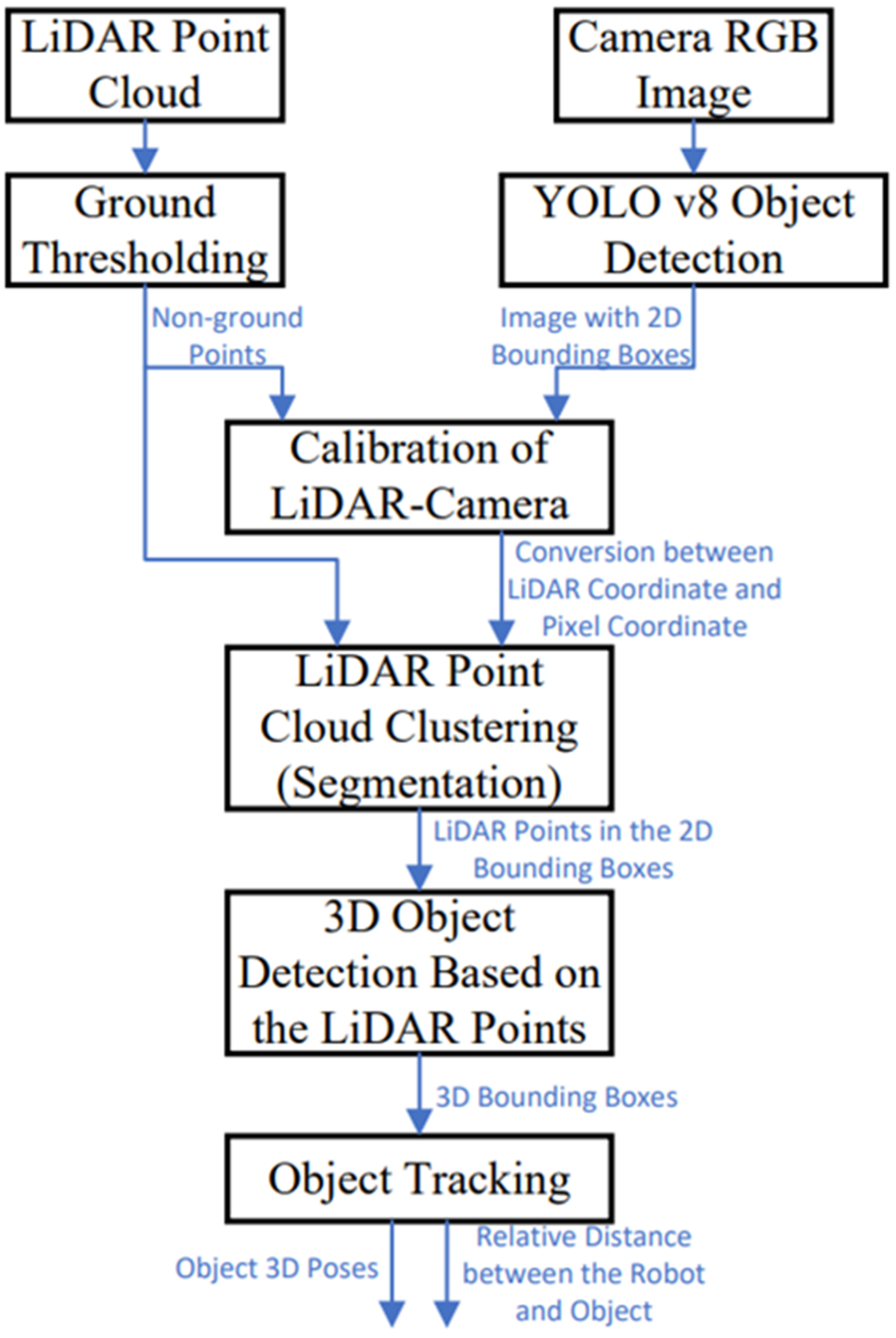
3.1. System Overview

The goal of this work is 3D object detection and tracking. The system structure addresses the object detection and tracking problem as shown in Figure 1. There are LiDAR point cloud input and camera RGB image input. After receiving the LiDAR point cloud data, the ground point is filtered. Then, the non-ground LiDAR points undergo the calibration process. After receiving the camera RGB image, YOLOv8 is used for object detection, based on a customized dataset. Then, the image with 2D bounding boxes undergoes the calibration process. In the calibration of the LiDAR–camera process, a simple LiDAR and camera fusion process is proposed to translate the coordinates of objects detected by LiDAR into the coordinate system of the camera image. The process includes data collection, coordinate transformation, feature extraction, calibration, and validation. The conversion between the LiDAR coordinate and the image pixel coordinate will be determined. Then, the LiDAR Point Cloud Clustering is processed. The pixel coordinates are in the 2D bounding boxes, based on the YOLO object detection result, and are recognized as the same object. According to the calibration results, the LiDAR points are segmented, with their transformed pixel coordinates within the 2D bounding boxes. Based on the top view result of the LiDAR points and LiDAR segmentation result, 3D bounding boxes for the LiDAR points can be obtained. The center of the bounding boxes is calculated. Then, we approach the object tracking algorithm to calculate the object’s 3D poses and determine the relative distance between the robot and the object.

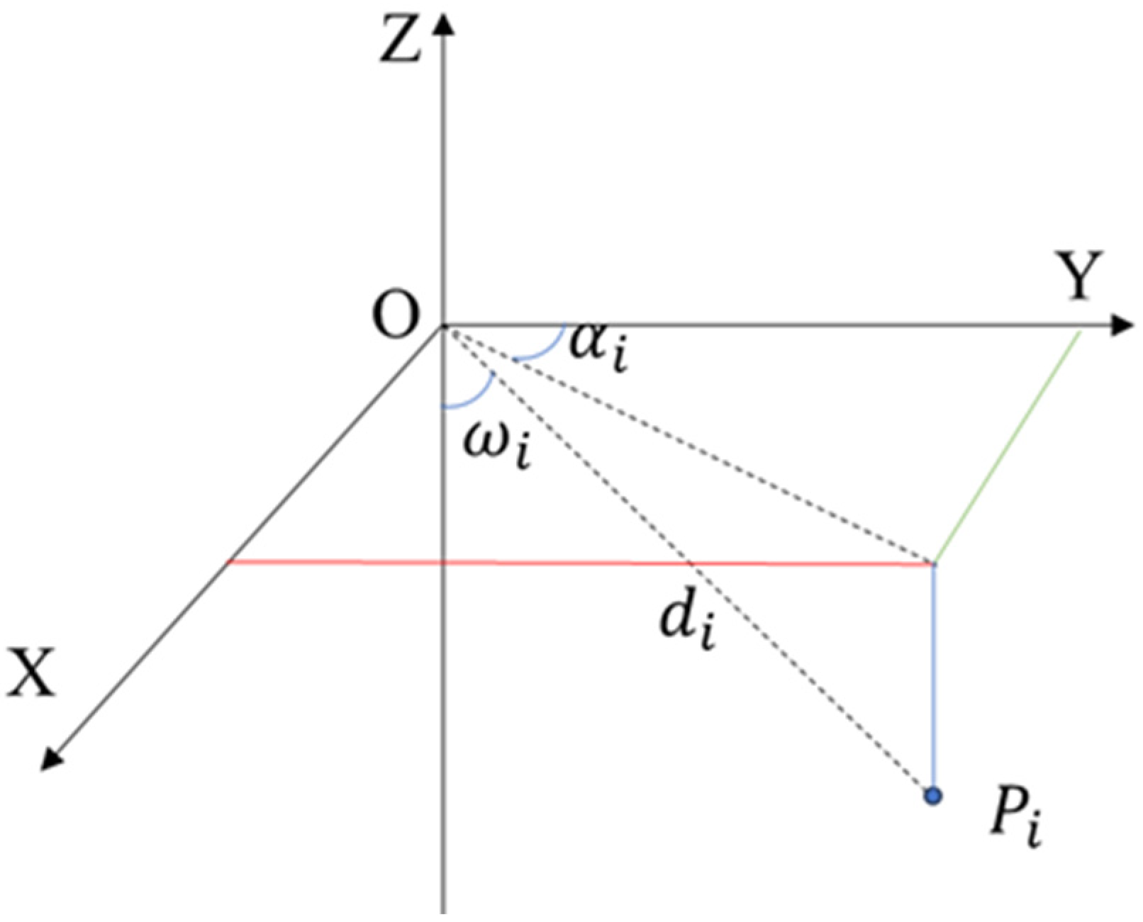
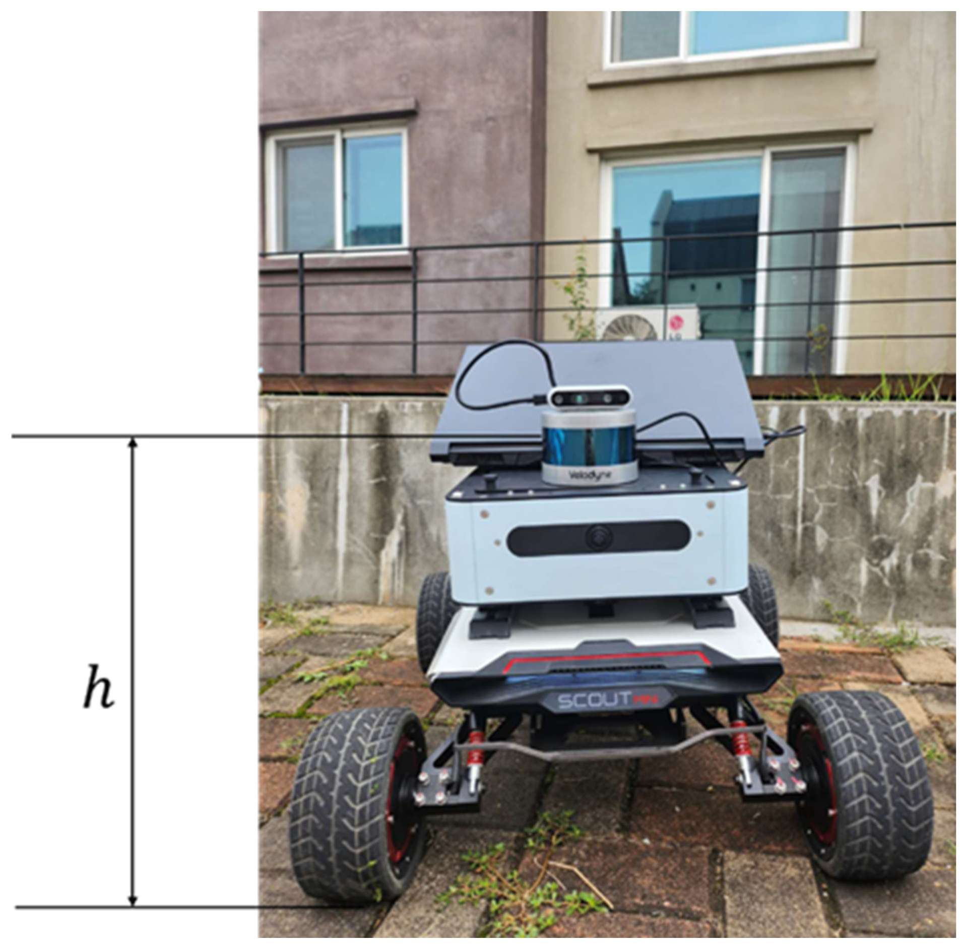
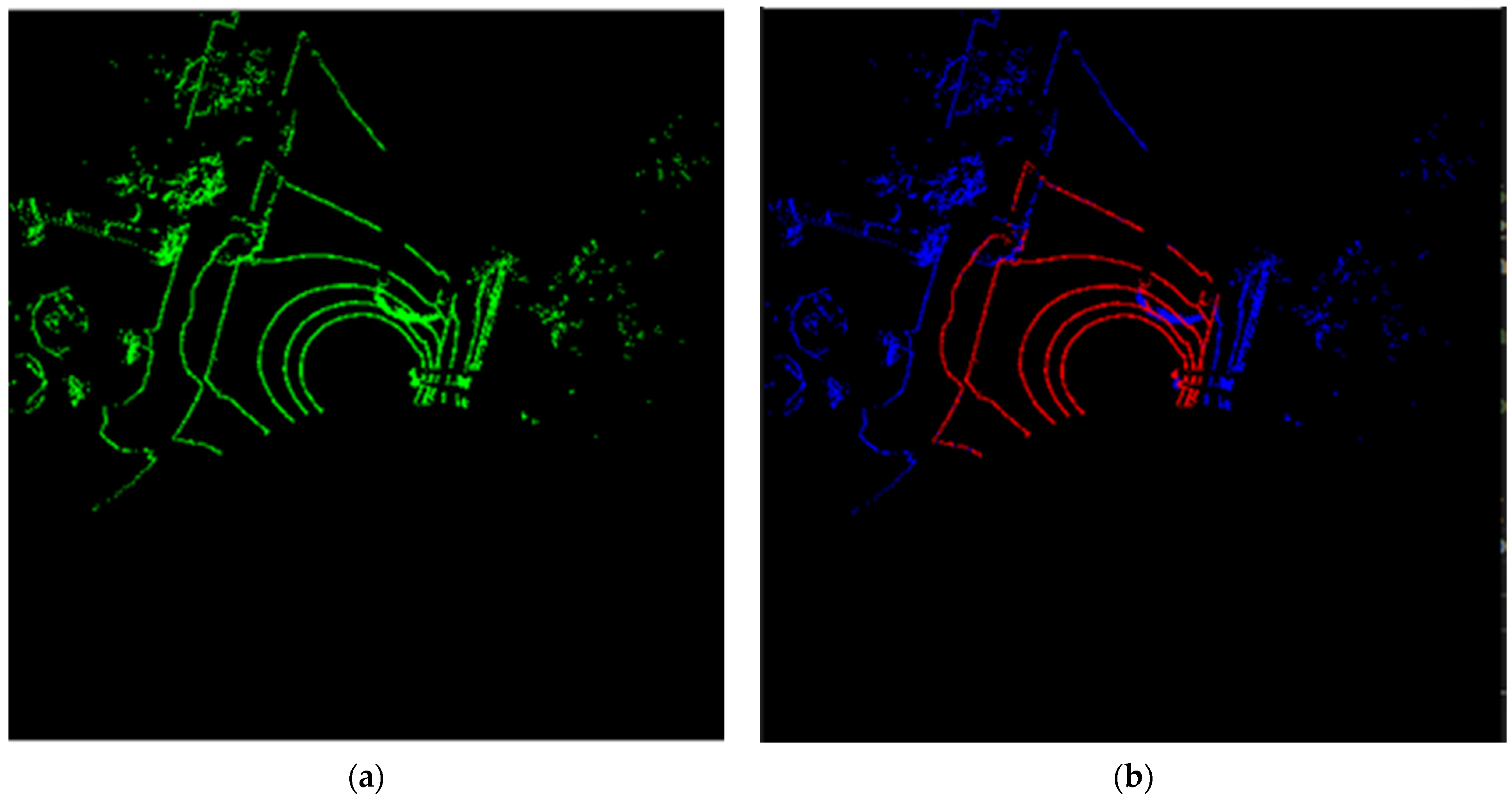
3.2. LiDAR Data Ground Segmentation

As shown in Figure 2, the LiDAR sensor reports points in spherical coordinates (detection distance d , elevation ω , and azimuth α ). There is a detected LiDAR point P i ( x i , y i , z i ) , where i is the point’s index number. The detection distance O P i is calculated as d i as follows:
d i = x i 2 + y i 2 + z i 2
The elevation ω i is the angle between the horizontal plane and the line to the target. ω i is calculated as follows:
ω i = a r c c o s ( z i d i )
The azimuth is the angular measurement in a spherical coordinate system. It is the angle between a reference direction and the line from the observer to the point of interest, projected onto the horizontal plane. The azimuth is measured in degrees, with values ranging from 0 to 360 degrees, usually in a clockwise direction from the reference direction. α i is calculated as follows:
α i = a t a n 2 ( x i , y i )
Convert the spherical data of point P i to the Cartesian coordinates. The transfer equations are as follows:
x i = d i cos ω i s i n ( α i )
y i = d i cos ω i c o s ( α i )
z i = d i sin ω i
In order to quickly process the ground segmentation algorithm, the LiDAR points with negative z-axis values are taken into account. A threshold height h t is defined to determine whether a point P i is classified as a ground point or a non-ground point. If the absolute of z i at point P i is greater than or equal to the threshold height h t , then the point P i is considered a detected ground point. Conversely, if the absolute of z i is less than the threshold height h , the point P i is classified as a non-ground point. However, the challenge lies in selecting the correct threshold height h t for effective ground point segmentation. Different road surfaces exhibit distinct characteristics. As shown in Figure 3, three conditions are considered to determine the threshold height h t : flat terrain, uphill terrain, and downhill terrain. In order to calculate the threshold height h t , two points, P i and P i + 1 , with the same azimuth are considered. The angle β is calculated as follows:
β = a t a n 2 ( z i + 1 z i , ( y i + 1 y i ) )
As shown in Figure 4, h represents the mounting height of the LiDAR above the ground. It is related to the height of the robot, the sensor bracket, and the size of the LiDAR sensor. A constant compensatory distance is defined as d c and the threshold height h t is calculated as (8), where β is calculated from (7). d c is a constant value, which is defined based on the distance between LiDAR and the object. It is equal to the average y-value of points with the same azimuth angle minus the minimum y-value.
h t = h + d c t a n ( β )
As shown in Figure 3a, the default road is a flat terrain road and β is zero. Therefore, the threshold height h t is equal to h . For the uphill condition, h t is lower than h . For the downhill condition, h t is higher than h . For the uphill and downhill conditions, d c is defined based on the real environment, for example, the distance of the detected object in front of the LiDAR.

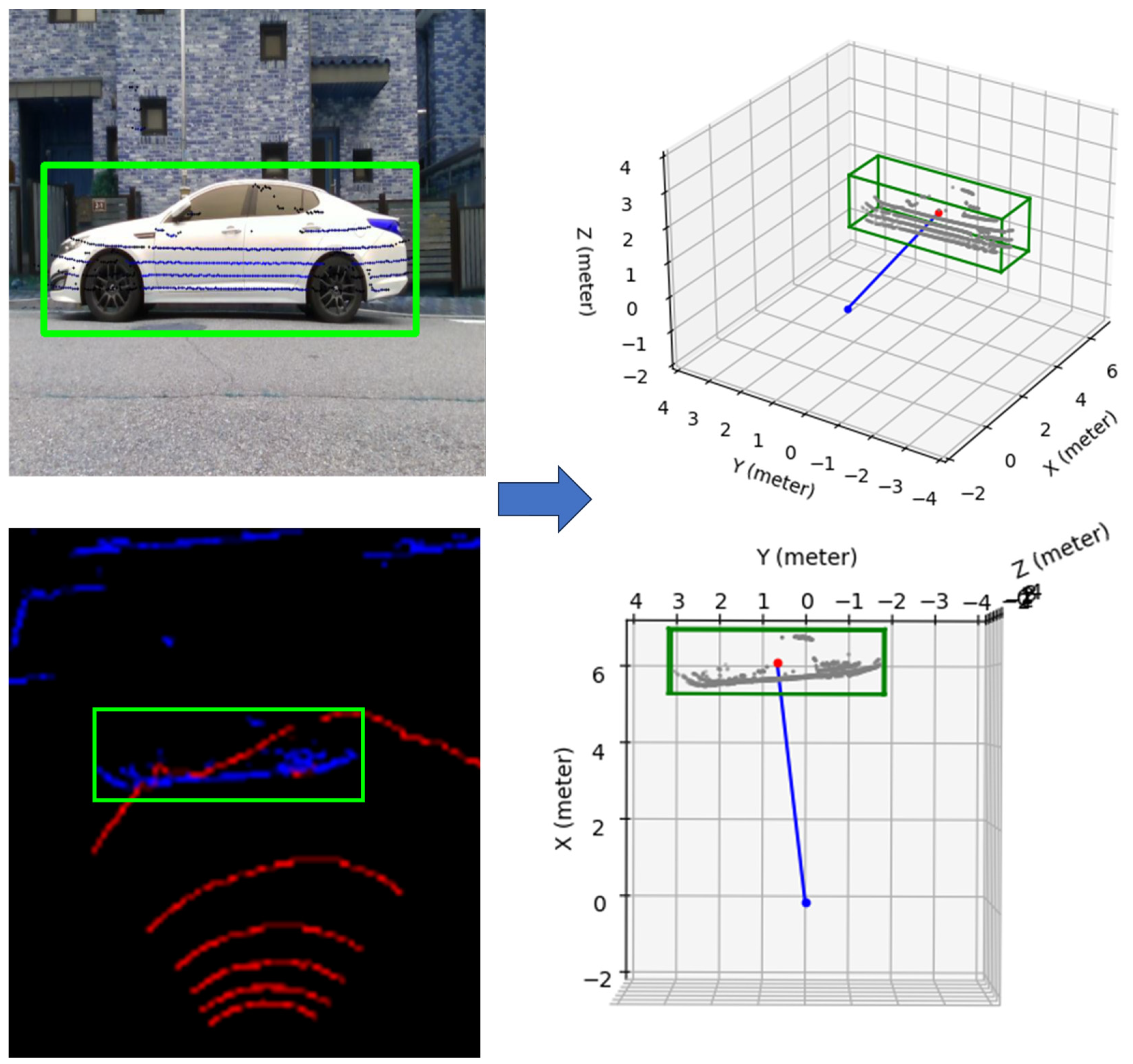
3.3. 3D LiDAR and Camera Data Fusion

In this section, a simple LiDAR and camera fusion process is proposed to translate the coordinates of objects detected by LiDAR into the coordinate system of the camera image. The process includes data collection, coordinate transformation, feature extraction, calibration, and validation. In the data collection process, based on the camera’s RGB Field of View (FOV), the right range of LiDAR points are collected. For example, as shown in Figure 4, When a Velodyne LiDAR and an Intel D435 camera are both facing forward and the camera’s RGB FOV is 69° × 42°, it implies that the LiDAR’s horizontal detection angle range should be matched with the camera’s horizontal FOV for effective data fusion. In this scenario, the LiDAR’s azimuth α is confined between 0 to 34.5 degrees and 315.5 to 360 degrees. This range ensures that the area covered by the LiDAR overlaps with the camera’s field of vision. This fusion enhances the accuracy of object detection and is highly beneficial for understanding the surroundings in complex environments. After collecting the right range of LiDAR data, the LiDAR point positions in Cartesian coordinates are calculated based on (4)–(6). LiDAR Data Ground Segmentation in Section 3.2 is used to filter the ground data. Then, among the non-ground in-range points, based on the distance from the LiDAR to the detection points and the value of inflection, some points are selected for calibration. As shown in Figure 5, the car is utilized for calibration. The distance between the LiDAR sensor and the car is measurable. The color of the car differs from that of its wheel. This distinction is significant because white and black surfaces reflect light differently, influencing the LiDAR reflection value. These contrasting colors allow for the selection of characteristic points for calibration. The positions of these selected LiDAR points are then recorded in both the LiDAR coordinate system and the camera’s pixel coordinate system.
In the calibration process, define a transformation matrix M , which converts the coordinate system of LiDAR to the coordinate system of the camera. The transformation matrix includes rotation, scaling, and translation.
M = a b c d e f g h i j k l 0 0 0 1
The homogeneous coordinate of LiDAR is P = [ x , y , z , 1 ] T . Then, the coordinates P = [ x , y , z , 1 ] T are obtained as follows:
P = M P = a x + b y + c z + d e x + f y + g z + h i x + j y + k z + l 1
To convert the homogeneous coordinates P into two-dimensional pixel coordinates [ u v ] T , firstly use perspective division to convert homogeneous coordinates into three-dimensional Cartesian coordinates, and then use the intrinsic parameter of the camera to transfer. The intrinsic parameter matrix of the camera is defined as (11).
K = f x 0 c x 0 f y c y 0 0 1
f x and f y are the focal lengths along the x and y axes, respectively, measured in pixels. c x and c y are the coordinates of the image’s center point. The two-dimensional pixel coordinates [ u v ] T can be obtained as follows:
u v 1 = K x y 1
The least squares method is used to find the parameters a , b , c , d , e , f , g , h , i , j , k , l in the transformation matrix M . An objective function f ( M ) is created to measure the difference between the LiDAR coordinates transformed by these parameters, based on (9)–(12), and the actual camera pixel coordinates [ u c v c ] T . The function f ( M ) is defined as follows:
f ( M ) = j = 1 n [ ( u j u c _ j ) 2 + ( v j v c _ j ) 2 ]
where n is the total number of calibration points and j is the index of the j t h calibration point. Through iterative optimization algorithms, the parameters of M are adjusted according to the gradient of the objective function, until the convergence criteria are met or the predetermined number of iterations is completed.

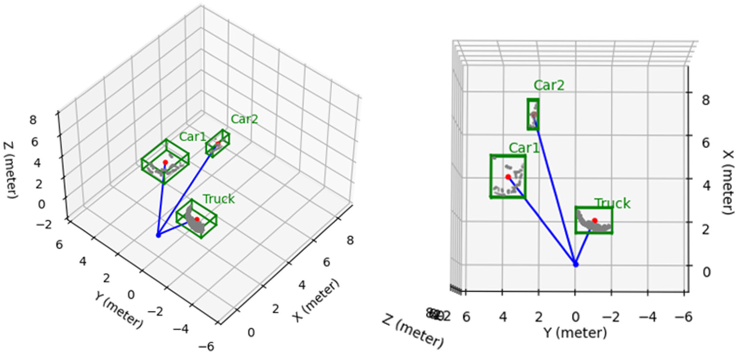
3.4. Object Detection and Tracking

In order to use YOLO v8 to detect the objects, a customized dataset is created. As shown in Figure 4, using Agilex’s Scout Mini robot equipped with an Intel D435 camera, images are collected in a residential community. The target categories include pedestrians, cars, motorcycles, bicycles, street lights, trees, and houses. Two lighting conditions are considered: bright light and darkness. Totally, 1694 images are used for training and 424 images are used for testing. LabelImg is used to create bounding boxes and label categories. The .txt file is created with the same name for each image, containing the labeled information. Set the configuration file and the training environment, and then the model is trained.
Based on the calibration process in Section 3.3, the LiDAR points are transformed in the pixel coordinates. For object tracking, LiDAR Point Cloud Clustering is integrated with the YOLO object detection result. As shown in Figure 6, the LiDAR data are used in conjunction with YOLO-detected objects. The pixel coordinates of these objects within 2D bounding boxes are identified as belonging to the same object. Based on the top view result of the LiDAR points, the LiDAR points P n = [ x n , y n , z n ] ( n = 1,2 , 3 , , n ) detected from the same object can be separated. Indicated as the red point shown in Figure 6, the center point C P = [ x c , y c , z c ] of the object can be calculated as follows:
x c = ( max x n min x n ) 2 + min x n
y c = ( max y n min y n ) 2 + min y n
z c = ( max z n min z n ) 2 + min z n
The center point is defined as the object point for tracking. The relative distance between the center point of the object and the LiDAR is as shown in (17):
d o l = x c 2 + y c 2 + z c 2
The elevation ω o l is calculated as follows:
ω o l = a r c c o s ( z c d o l )
Based on (1) in [36], the LiDAR coordinate can be transferred to the world coordinate. Therefore, based on (14)–(18), the coordinates of the center point in the world coordinate system can be calculated. In order to obtain the 3D bounding box of the objects, the length, width, and height of the box can be calculated as follows:
l e n g t h = max x n min x n + m
w i d t h = max y n min y n + m
h e i g h t = max z n min z n + m
where m is the extended distance. The corner coordinates of the box are obtained as follows:
c o r n e r s = x c l e n g t h 2 y c w i d t h 2 z c h e i g h t 2 x c + l e n g t h 2 y c w i d t h 2 z c h e i g h t 2 x c + l e n g t h 2 y c + w i d t h 2 z c h e i g h t 2 x c l e n g t h 2 y c + w i d t h 2 z c h e i g h t 2 x c l e n g t h 2 y c w i d t h 2 z c + h e i g h t 2 x c + l e n g t h 2 y c w i d t h 2 z c + h e i g h t 2 x c + l e n g t h 2 y c + w i d t h 2 z c + h e i g h t 2 x c l e n g t h 2 y c + w i d t h 2 z c + h e i g h t 2

4. Simulations and Experiment

In this section, the data are collected by using the Agilex Scout Mini onboard PC. As shown in Figure 4, a Velodyne LiDAR and an Intel D435 camera are mounted on the robot. Both sensors face forward, the x-axis of the robot’s moving direction. The camera’s RGB FOV is 69° × 42°, and it implies that the LiDAR’s horizontal detection angle range should be matched with the camera’s horizontal FOV for effective data fusion. In the experiment, the LiDAR’s azimuth α is confined between 0 to 34.5 degrees and 315.5 to 360 degrees. The mounting height of the LiDAR above the ground is 0.412 m. d c is defined based on the real environment, for example, the distance of the detected object in front of the LiDAR. The parameters a , b , c , d , e , f , g , h , i , j , k , l in the transformation matrix M are obtained as [28.6197, −93.72131, 156.6157, 291.09294, −52.93593, 27.92016, −310.95358, 407.69218, 0.8058, 0.45731, 0.77985, 0.82676]. For object detection using YOLOv8, the target categories include pedestrians, cars, motorcycles, bicycles, street lights, trees, and houses. Two lighting conditions are considered: bright light and darkness. Totally, 1694 images are used for training and 424 images are used for testing. The model is selected as the YOLOv8n model.
The experimental design involves the following steps: LiDAR data ground segmentation, object detection, LiDAR–camera data calibration, object tracking, and 3D bounding box construction.
Figure 7 shows the results of the LiDAR data ground segmentation. Figure 7a is the top-view result of all LiDAR point cloud data. Figure 7b displays the results of ground segmentation, where red points represent ground points and blue points represent non-ground points. As shown in Figure 4, the mounting height of the LiDAR above the ground is 0.412 m. The ground points are correctly identified and separated from non-ground points.
The object detection process, based on YOLOv8, efficiently and accurately identifies two cars and one truck, as shown in Figure 8. The object tracking algorithm uses the detection results from Figure 8.
As shown in Figure 8, three objects are detected. Based on the calibration process in Section 3.3, the LiDAR points are transformed in the pixel coordinates. The LiDAR data are used in conjunction with the object detection results. The pixel coordinates of the truck and two cars within 2D bounding boxes are identified as belonging to the same object. The results are shown in Figure 9. The green points, red points, and blue points are the detected LiDAR points of the truck, black car, and white car, separately. The transformed lidar points coincide with the actual pixel coordinates of the detected object. Therefore, the calibration precision is acceptable. Despite occlusions and missing parts between the cars and truck, the LiDAR points can still be well segmented and accurately matched with their respective detected objects.
Based on the object detection and calibration results in Figure 9 and the top-view result of all LiDAR point cloud data in Figure 7b, 3D bounding boxes are constructed to represent each object, as depicted in Figure 10. The red points indicate the central points for the 3D bounding boxes. The coordinates for the central points of the truck, Car1, and Car2, relative to the robot’s zero point, are as follows: 1.96 1.01 0.25 T , 3.92 3.63 0.14 T , and 6.76 2.03 0.5 T , separately. The corners’ coordinates for the bounding box of the truck are as in (23). The length, width, and height of the truck bounding box are 1.96 m, 1.15 m, and 0.96 m.
c o r n e r s t r u c k = 1.38 1.99 0.23   2.53 1.99 0.23 2.53 0.03 0.23 1.38 0.03 0.23 1.38 1.99 0.73 2.53 1.99 0.73 2.53 0.03 0.73 1.38 0.03 0.73
The corners’ coordinates for the bounding box of Car1 are as in (24). The length, width, and height of the truck bounding box are 1.86 m, 1.88 m, and 1.04 m.
c o r n e r s c a r 1 = 2.98 2.71 0.38   4.86 2.71 0.38 4.86 4.57 0.38 2.98 4.57 0.38 2.98 2.71 0.66 4.86 2.71 0.66 4.86 4.57 0.66 2.98 4.57 0.66
The corners’ coordinates for the bounding box of Car2 are as in (25). The length, width, and height of the truck bounding box are 1.31 m, 0.54 m, and 0.97 m.
c o r n e r s c a r 2 = 6.11 2.04 0.5   7.42 2.04 0.5 7.42 2.58 0.5 6.11 2.58 0.5 6.11 2.04 0.47 7.42 2.04 0.47 7.42 2.58 0.47 6.11 2.58 0.47
The dimensions of the 3D bounding boxes closely match the dimensions of the objects detected by the 3D LiDAR.

5. Conclusions

This paper presents an innovative and effective approach to object detection and tracking. A novel algorithm is proposed to filter ground points from LiDAR data, which is critical for the accuracy of subsequent detection processes. YOLOv8 was used for object detection, which was trained on a customized dataset. It outputs the image through 2D bounding boxes. The development of a calibration algorithm that transforms 3D LiDAR coordinates to image pixel coordinates is a key contribution, enabling the effective correlation of LiDAR data with object detection results. This is further enhanced by a proposed method for object clustering based on combined data from object detection and LiDAR calibration. An object tracking algorithm is proposed to compute the 3D poses and relative distances of objects in relation to a robot. The Agilex Scout Mini robot, equipped with Velodyne 16-channel LiDAR and an Intel D435 camera, was applied for data collection and experimentation. The experimental results show the efficiency and effectiveness of the algorithms. Future research will focus on enhancing the diversity of object recognition and tracking, as well as improving the accuracy of object tracking.

Author Contributions

Conceptualization, Y.D.; methodology, Y.D.; software, Y.D.; validation, Y.D.; formal analysis, Y.D.; investigation, Y.D. and D.K.; resources, Y.D.; data curation, Y.D.; writing—original draft preparation, Y.D.; writing—review and editing, Y.D. and K.L.; visualization, Y.D.; supervision, Y.D.; project administration, Y.D.; funding acquisition, K.L. All authors have read and agreed to the published version of the manuscript.

Funding

This paper was supported by Korea Institute for Advancement of Technology (KIAT) grant funded by the Korea Government (MOTIE) (RS-2024-00406796, HRD Program for Industrial Innovation).

Data Availability Statement

The raw data supporting the conclusions of this article will be made available by the authors on request.

Conflicts of Interest

The authors declare no conflicts of interest.

Abbreviations

LiDARLight Detection and Ranging
YOLOYou Only Look Once
SSDSingle Shot MultiBox Detector
FOVField of View
2DTwo dimensional
3DThree dimensional

References

  1. Mehdi, S.M.; Naqvi, R.A.; Mehdi, S.Z. Autonomous object detection and tracking robot using Kinect v2. In Proceedings of the 2021 International Conference on Innovative Computing (ICIC), Lahore, Pakistan, 9–10 November 2021; pp. 1–6. [Google Scholar] [CrossRef]
  2. Lee, M.-F.R.; Chen, Y.-C. Artificial Intelligence Based Object Detection and Tracking for a Small Underwater Robot. Processes 2023, 11, 312. [Google Scholar] [CrossRef]
  3. Xu, Z.; Zhan, X.; Xiu, Y.; Suzuki, C.; Sh, K. Onboard Dynamic-object Detection and Tracking for Autonomous Robot Navigation with RGB-D Camera. IEEE Robot. Autom. Lett. 2024, 9, 651–658. [Google Scholar] [CrossRef]
  4. Gragnaniello, D.; Greco, A.; Saggese, A.; Vento, M.; Vicinanza, A. Benchmarking 2D Multi-Object Detection and Tracking Algorithms in Autonomous Vehicle Driving Scenarios. Sensors 2023, 23, 4024. [Google Scholar] [CrossRef]
  5. Mendhe, A.; Chaudhari, H.B.; Diwan, A.; Rathod, S.M.; Sharma, A. Object Detection and Tracking for Autonomous Vehicle using AI in CARLA. In Proceedings of the 2022 International Conference on Industry 4.0 Technology (I4Tech), Pune, India, 23–24 September 2022; pp. 1–5. [Google Scholar] [CrossRef]
  6. Xie, D.; Xu, Y.; Wang, R. Obstacle detection and tracking method for autonomous vehicle based on three-dimensional LiDAR. Int. J. Adv. Robot. Syst. 2019, 16, 172988141983158. [Google Scholar] [CrossRef]
  7. Nguyen, P.A.; Tran, S.T. Tracking customers in crowded retail scenes with Siamese Tracker. In Proceedings of the 2020 RIVF International Conference on Computing and Communication Technologies (RIVF), Ho Chi Minh City, Vietnam, 14–15 October 2020; pp. 1–6. [Google Scholar] [CrossRef]
  8. Lee, J.; Moon, S.; Nam, D.-W.; Lee, J.; Oh, A.R.; Yoo, W. A Study on Sports Player Tracking based on Video using Deep Learning. In Proceedings of the 2020 International Conference on Information and Communication Technology Convergence (ICTC), Jeju, Republic of Korea, 21–23 October 2020; pp. 1161–1163. [Google Scholar] [CrossRef]
  9. Ouardirhi, Z.; Mahmoudi, S.A.; Zbakh, M. Enhancing Object Detection in Smart Video Surveillance: A Survey of Occlusion-Handling Approaches. Electronics 2024, 13, 541. [Google Scholar] [CrossRef]
  10. Azevedo, P.; Santos, V. YOLO-Based Object Detection and Tracking for Autonomous Vehicles Using Edge Devices. In ROBOT2022: Fifth Iberian Robotics Conference; Springer: Berlin/Heidelberg, Germany, 2022; pp. 297–308. [Google Scholar] [CrossRef]
  11. Gupta, A.; Anpalagan, A.; Guan, L.; Khwaja, A.S. Deep learning for object detection and scene perception in self-driving cars: Survey, challenges and issues. Array 2021, 10, 100057. [Google Scholar] [CrossRef]
  12. Moksyakov, A.; Wu, Y.; Gadsden, S.A.; Yawney, J.; AlShabi, M. Object Detection and Tracking with YOLO and the Sliding Innovation Filter. Sensors 2024, 24, 2107. [Google Scholar] [CrossRef]
  13. Balamurali, M.; Mihankhah, E. SimMining-3D: Altitude-Aware 3D Object Detection in Complex Mining Environments: A Novel Dataset and ROS-Based Automatic Annotation Pipeline. arXiv 2023, arXiv:2312.06113. [Google Scholar] [CrossRef]
  14. Dippal, I.; Hiren, M. Identity Retention of Multiple Objects under Extreme Occlusion Scenarios using Feature Descriptors. J. Commun. Softw. Syst. 2018, 14, 290–301. [Google Scholar] [CrossRef]
  15. Luo, W.; Xing, J.; Milan, A.; Zhang, X.; Liu, W.; Kim, T.-K. Multiple object tracking: A literature review. Artif. Intell. 2021, 293, 103448. [Google Scholar] [CrossRef]
  16. Wu, Y.; Wang, Y.; Liao, Y.; Wu, F.; Ye, H.; Li, S. Tracking Transforming Objects: A Benchmark. arXiv 2024, arXiv:2404.18143v1. [Google Scholar]
  17. Gomes, T.; Matias, D.; Campos, A.; Cunha, L.; Roriz, R. A Survey on Ground Segmentation Methods for Automotive LiDAR Sensors. Sensors 2023, 23, 601. [Google Scholar] [CrossRef]
  18. Deng, W.; Chen, X.; Jiang, J. A Staged Real-Time Ground Segmentation Algorithm of 3D LiDAR Point Cloud. Electronics 2024, 13, 841. [Google Scholar] [CrossRef]
  19. Redmon, J.; Divvala, S.; Girshick, R.; Farhadi, A. You Only Look Once: Unified, Real-Time Object Detection. arXiv 2015, arXiv:1506.02640. [Google Scholar]
  20. Liu, W.; Anguelov, D.; Erhan, D.; Szegedy, C.; Reed, S.; Fu, C.-Y.; Berg, A.C. SSD: Single Shot MultiBox Detector. In Computer Vision—ECCV 2016. ECCV 2016; Leibe, B., Matas, J., Sebe, N., Welling, M., Eds.; Lecture Notes in Computer Science; Springer: Cham, Switzerland, 2016; Volume 9905. [Google Scholar] [CrossRef]
  21. Ren, S.; He, K.; Girshick, R.; Sun, J. Faster R-CNN: Towards Real-Time Object Detection with Region Proposal Networks. arXiv 2015, arXiv:1506.01497. [Google Scholar] [CrossRef]
  22. Bharat Mahaur, B.; Mishra, K.K. Small-object detection based on YOLOv5 in autonomous driving systems. Pattern Recognit. Lett. 2023, 168, 115–122. [Google Scholar] [CrossRef]
  23. Li, C.; Li, L.; Jiang, H.; Weng, K.; Geng, Y.; Li, L.; Ke, Z.; Li, Q.; Cheng, M.; Nie, W.; et al. YOLOv6: A Single-Stage Object Detection Framework for Industrial Applications. arXiv 2022, arXiv:2209.02976. [Google Scholar]
  24. Li, K.; Wang, Y.; Hu, Z. Improved YOLOv7 for Small Object Detection Algorithm Based on Attention and Dynamic Convolution. Appl. Sci. 2023, 13, 9316. [Google Scholar] [CrossRef]
  25. Huang, H.; Wang, B.; Xiao, J.; Zhu, T. Improved small-object detection using YOLOv8: A comparative study. Appl. Comput. Eng. 2024, 41, 80–88. [Google Scholar] [CrossRef]
  26. Lee, J.; Su, Y. Balancing Privacy and Accuracy: Exploring the Impact of Data Anonymization on Deep Learning Models in Computer Vision. IEEE Access 2024, 12, 8346–8358. [Google Scholar] [CrossRef]
  27. Liu, Y.; Jiang, X.; Cao, W.; Sun, J.; Gao, F. Detection of Thrombin Based on Fluorescence Energy Transfer Between Semiconducting Polymer Dots and BHQ-Labelled Aptamers. Sensors 2018, 18, 589. [Google Scholar] [CrossRef]
  28. Noguera, J.M.; Jiménez, J.R. Mobile Volume Rendering: Past, Present and Future. IEEE Trans. Vis. Comput. Graph. 2016, 22, 1164–1178. [Google Scholar] [CrossRef]
  29. Kwak, K.; Huber, D.F.; Badino, H.; Kanade, T. Extrinsic Calibration of a Single Line Scanning Lidar and a Camera. In Proceedings of the 2011 IEEE/RSJ International Conference on Intelligent Robots and Systems, San Francisco, CA, USA, 25–30 September 2011; pp. 3283–3289. [Google Scholar]
  30. Gunjal, P.R.; Gunjal, B.R.; Shinde, H.A.; Vanam, S.M.; Aher, S.S. Moving Object Tracking Using Kalman Filter. In Proceedings of the 2018 International Conference on Advances in Communication and Computing Technology (ICACCT), Sangamner, India, 8–9 February 2018; pp. 544–547. [Google Scholar] [CrossRef]
  31. Feng, Z. High Speed Moving Target Tracking Algorithm based on Mean Shift for Video Human Motion. J. Phys. Conf. Ser. 2021, 1744, 042180. [Google Scholar] [CrossRef]
  32. Liu, H.; Wu, C.; Wang, H. Real time object detection using LiDAR and camera fusion for autonomous driving. Sci. Rep. 2023, 13, 8056. [Google Scholar] [CrossRef]
  33. Kim, T.-L.; Park, T.-H. Camera-LiDAR Fusion Method with Feature Switch Layer for Object Detection Networks. Sensors 2022, 22, 7163. [Google Scholar] [CrossRef]
  34. Shen, Z.; Liang, H.; Lin, L.; Wang, Z.; Huang, W.; Yu, J. Fast Ground Segmentation for 3D LiDAR Point Cloud Based on Jump-Convolution-Process. Remote Sens. 2021, 13, 3239. [Google Scholar] [CrossRef]
  35. Paigwar, A.; Erkent, Ö.; González, D.S.; Laugier, C. GndNet: Fast Ground Plane Estimation and Point Cloud Segmentation for Autonomous Vehicles. In Proceedings of the IROS 2020-IEEE/RSJ International Conference on Intelligent Robots and Systems, Las Vegas, NV, USA, 24 October 2020–24 January 2021; pp. 2150–2156. [Google Scholar] [CrossRef]
  36. Dai, Y.; Lee, K. 3D map building based on extrinsic sensor calibration method and object contour detector with a fully convolutional neural network. Meas. Control. 2023, 56, 215–227. [Google Scholar] [CrossRef]
Figure 1. System structure of 3D object detection and tracking.
Electronics 13 02250 g001
Figure 2. LiDAR point in the coordinate system to segment the ground point.
Electronics 13 02250 g002
Figure 3. The three conditions to determine the threshold height: (a) flat terrain, (b) uphill terrain, and (c) downhill terrain.
Electronics 13 02250 g003
Figure 4. The height of the LiDAR sensor from the ground in a real environment.
Electronics 13 02250 g004
Figure 5. Environment for LiDAR and camera data fusion.
Electronics 13 02250 g005
Figure 6. Object detection and tracking. On the left side, the detected car is in the green block. On the right side, the detected car’s 3D bounding box is shown as a green box. The red point is used to calculate the detected car’s pose.
Electronics 13 02250 g006
Figure 7. The results of the LiDAR data ground segmentation. (a) Top-view result of all LiDAR point cloud data; (b) ground segmentation result: red points represent ground points and blue points represent non-ground points.
Electronics 13 02250 g007
Figure 8. Object detection result using YOLOv8.
Electronics 13 02250 g008
Figure 9. Object detection result and LiDAR point calibration results.
Electronics 13 02250 g009
Figure 10. Object tracking result.
Electronics 13 02250 g010
Disclaimer/Publisher’s Note: The statements, opinions and data contained in all publications are solely those of the individual author(s) and contributor(s) and not of MDPI and/or the editor(s). MDPI and/or the editor(s) disclaim responsibility for any injury to people or property resulting from any ideas, methods, instructions or products referred to in the content.

