Article

Designing Multifunctional Multiferroic Composites for Advanced Electronic Applications

by
Lilian Nunes Pereira
1,
Julio Cesar Agreira Pastoril
1,
Gustavo Sanguino Dias
1,
Ivair Aparecido dos Santos
1,
Ruyan Guo
2,
Amar S. Bhalla
2 and
Luiz Fernando Cotica
1,*
1
Department of Physics, State University of Maringa, 5790 Av. Colombo, Maringa 87020-900, PR, Brazil
2
Department of Electrical and Computer Engineering, University of Texas at San Antonio, One UTSA Circle, San Antonio, TX 78249, USA
*
Author to whom correspondence should be addressed.
Electronics 2024, 13(12), 2266; https://doi.org/10.3390/electronics13122266
Submission received: 25 April 2024 / Revised: 3 June 2024 / Accepted: 7 June 2024 / Published: 9 June 2024
(This article belongs to the Special Issue Advanced Materials for Intelligent Electronics)

Abstract

:
This paper presents a novel approach for the fabrication of magnetoelectric composites aimed at enhancing cross-coupling between electrical and magnetic phases for potential applications in intelligent sensors and electronic components. Unlike previous methodologies known for their complexity and expense, our method offers a simple and cost-effective assembly process conducted at room temperature, preserving the original properties of the components and avoiding undesired phases. The composites, composed of PZT fibers, cobalt (CoFe2O4), and a polymeric resin, demonstrate the uniform distribution of PZT-5A fibers within the cobalt matrix, as demonstrated by scanning electron microscopy. Detailed morphological analyses reveal the interface characteristics crucial for determining overall performance. Dielectric measurements indicate stable behaviors, particularly when PZT-5A fibers are properly poled, showcasing potential applications in sensors or medical devices. Furthermore, H-dependence studies illustrate strong magnetoelectric interactions, suggesting promising avenues for enhancing coupling efficiency. Overall, this study lays the basic work for future optimization of composite composition and exploration of its long-term stability, offering valuable insights into the potential applications of magnetoelectric composites in various technological domains.

1. Introduction

Human progress is closely tied to advancements in materials that improve living standards. Present technologies owe much to materials science, especially multifunctional materials. These are created by combining different physical properties into one substance, leading to key technological innovations. This has given rise to multiferroics with magnetoelectric (ME) properties, a class of materials with significant future potential [1].
Multiferroics, which possess two or more ferric orders, can convert magnetic properties to electrical and vice versa [2]. Research has been sparked by their capacity to combine these qualities in a single material, especially for the creation of intelligent electronic components. Multiferroic composites can generate significant magnetoelectric coupling above room temperature, which makes them suitable for technology applications even though natural multiferroics are uncommon and frequently impractical [3].
Magnetoelectric composites can be synthesized through various approaches, each of which significantly influences their properties. The different composite connectivities, namely 1–3, 0–3, and 2–2 play a crucial role in determining the magnetoelectric (ME) properties of these materials. Connectivity refers to the specific arrangement of ferroelectric and magnetostrictive phases within the composite.
The 0–3 particulate composites, characterized by a high concentration of magnetic nanoparticles dispersed within a ferroelectric matrix, exhibit enhanced magnetoelectric coupling [4,5]. This configuration promotes strong interactions between the magnetic and ferroelectric components, leading to significant ME effects. In contrast, the 1–3 composites, which consist of a magnetostrictive matrix embedded with piezoelectric fibers or rods, demonstrate moderate ME coupling due to the direct interaction between the piezoelectric and magnetostrictive phases [4,6]. The 2–2 composites, where ferroelectric and magnetic layers are alternately stacked, display relatively weaker ME coupling. This reduced interaction between the magnetic and ferroelectric layers results in a more linear response with less nonlinear behavior compared to the 0–3 and 1–3 composites [4,6]. Despite their weaker coupling, the simpler architectures and lower material requirements of 1–3 and 2–2 composites offer more scalable solutions with moderate ME coupling [4,6].
Hence, the connectivity of the composite phases is a critical factor in determining the magnetoelectric coupling and nonlinear responses of ME composites. The choice of connectivity should be carefully considered to optimize the material properties for specific applications. In fact, recent research efforts [7,8,9,10] have focused on the development and enhancement of composites and connectivity schemes for the fabrication of miniaturized sensors exhibiting the magnetoelectric effect. Several factors like thickness, voltage constant, interface and material characteristics, volume fraction, phase composition, and particle shape influence the magnetoelectric properties of composites. Recent years have seen increased research on magnetoelectric composites and their derived devices, with a range of potential applications from low-power sensing to high-power conversion, underscoring their versatility [11]. Actually, mechanical stress mediates the ME coupling in the magnetoelectric composites, which are two-phase systems. An alternating magnetic field acting on a magnetostrictive component produces the stress.
Historical research on magnetoelectric composites includes Nan et al.’s theoretical analysis on different compositions and shapes of BaTiO3-CoFe2O4 composites [12]. Lopatin et al. found that composites of lead zirconate titanate (Pb[ Zr x Ti 1 x ]O3 or PZT) and ferrite displayed significant piezoelectric sensitivity [13]. Ryu et al. noticed an increase in the magnetoelectric voltage coefficient in certain conditions with PZT and Terfenol-D laminates [14]. Cho et al. highlighted the influence of piezoelectric material losses on the sensitivity of a PZT and Metglas laminate [15]. Lastly, Tian et al. discovered that the effective magnetoelectric coefficient of composites with elliptical nanofibers was influenced by various factors, such as the interface parameters, elliptical aspect ratio, material properties of both fiber and matrix and fiber volume fraction [16].
An essential component of magnetoelectric composite applications is the detection of magnetic fields. Because of their electrical and magnetic cross-coupling, these composites, also referred to as multifunctional sensors [17], can function as room-temperature detectors of very low magnetic fields, roughly at the picotesla level. In particular, the detection of low-intensity and low-frequency magnetic fields has numerous applications in electrical network monitoring and biomedical fields. i.e., these characteristics categorize these sensors as specifically designed for monitoring and diagnosing biomagnetic signals, particularly in applications such as magnetocardiography (MCG) and magnetoencephalography (MEG) [18,19,20].
Concerning the sensitivities of multifunctional sensors, they are required not only to operate in extremely low magnetic fields but also to function within the frequency range of 0.1 Hz to 100 Hz to detect biomagnetic signals. This frequency range is typical for MCG and MEG, presenting an alternative to commercial devices. In cardiac and cerebral diagnostics, the commonly used equipment possessing sensitivity within this frequency range is known as Squids (superconducting quantum interference devices). However, these devices incur substantial costs for acquisition, operation, and maintenance due to their operation at cryogenic temperatures of 4.2 K, in addition to their high energy consumption.
As an example, the work of Gao et al. [21] introduced a quasi-static charge amplifier method for detecting the extremely low-frequency response in Metglas/Pb(Mg1/3Nb2/3)O3-PbTiO3 magnetoelectric laminated composites. This method allows for the detection of the ME effect at frequencies as low as 2 Hz and demonstrates good stability of ME charge coefficients over a broad frequency range, spanning from 10 mHz to 1 kHz. Also, Duc et al. [22] have fabricated magnetoelectric composites by intercalating a lead titanate laminate between two magnetostrictive films. They created a magnetic sensor that operates in an AC magnetic field of 0.1 mT and resonates at a frequency of 40 Hz. The ME voltage response to applied magnetic fields was found to be as high as 130 mV/mT (dVME/dH).
The applications of magnetoelectric composites extend to submillimeter-sized ME devices, possessing great potential for the development of new microelectromechanical systems (MEMS). This perspective is particularly important for micro-ME array applications, where miniaturization of ME devices opens avenues for creating arrays capable of detecting and responding to subtle magnetic and mechanical stimuli [23]. More recently, there have also been studies on nanoelectromechanical systems (NEMS), representing a category of devices that seamlessly integrate electrical and mechanical functionalities at the nanoscale [24,25]. Notably, NEMS have demonstrated successful applications in the development of miniaturized mechanical antennas, presenting advantages in size reduction compared to traditional antennas driven by radio frequency (RF) current [26].
As a specific case, the primary applications of 1–3 magnetoelectric (ME) composites enclose a wide range of advanced technological domains. These composites play an important role in the development of high-sensitivity magnetic field sensors, which can detect very slight changes in magnetic fields [9]. Additionally, they can be used as efficient transducers, facilitating the conversion of magnetic fields into electric signals and vice versa. In the domain of signal processing, 1–3 ME composites are utilized in filters and oscillators, which most likely enable the tuning of magnetic fields based on electric signals, establishing particularly beneficial microwave device applications. Moreover, these composites can also be employed in phase shifters, allowing for the adjustment of the phase of magnetic fields in response to electric signals. In the context of data storage, they are fundamental in the design of memory devices that store magnetic information modulated by electric signals, therefore enhancing the performance of magnetic storage solutions. The miniaturization capabilities of 1–3 ME composites make them suitable for micro-devices that detect and manipulate magnetic fields at the nanoscale [9]. Furthermore, they are advantageous in high-frequency applications, exemplified by thin PZT/epoxy composites that generate high-frequency output voltages [27]. These diverse applications exploit the unique properties of 1–3 ME composites, notably their ability to convert magnetic fields into electric signals and vice versa, along with their high sensitivity and tunability.
Several published works demonstrate the use of piezoelectric layers or fibers and magnetic composites to improve cross-coupling between electrical and magnetic phases, leading to an increased magnetoelectric coefficient [25,28,29,30]. In our work, the composite has been designed and built from PZT fibers, cobalt ferrite (CoFe2O4) nanoparticles and a polymeric resin. This makes the assembly of the composite easy, cheap, and completely carried out at room temperature, maintaining all the original properties of the components and avoiding unwanted phases.
However, these methods often fail to produce materials with favorable magnetoelectric properties and free from secondary phases. Novel unsintered methods for the assembly of composites involve techniques that do not require high-temperature sintering processes. These methods include techniques such as electrochemical deposition, sol–gel processing, and 3D printing. They offer various advantages, such as improved control over the composition and structure of the composite, reduced processing time, and enhanced mechanical properties [4,9]. In particular, for the ME composites assembling, novel unsintered methods, such as phosphate bonding bulk [31] or laminate [32] and fluid-based [33] have been emerged in recent years.
In summary, current methods for preparing piezoelectric/magnetostrictive composites are expensive and complex. This work proposes an unsintered synthesis method to create 1–3 magnetoelectric composites. This approach aims to simplify the preparation process while maintaining or improving the desired magnetoelectric properties. There is a significant need to develop simpler and more cost-effective methods for synthesizing high-quality magnetoelectric composites. By exploring the magnetoelectric properties of these novel 1–3 composites, this research could lead to advancements in intelligent and multifunctional electronic components, particularly in magnetic field detection.

2. Experimental

2.1. Cobalt Ferrite Nanoparticles Synthesis

The cobalt ferrite nanoparticles were synthesized using the high-energy ball milling technique. Initially, cobalt oxide, Co3O4, and iron oxide, α -Fe2O3, analytical grade powders (Aldrich, Saint Louis, MO, USA) were employed on the stoichiometric equation 6Fe2O3 + 2Co3O4→6CoFe2O4. The powders were mixed in an agate mortar for 15 min and then placed in a 125 mL hardened carbon steel vial with 5 mm diameter hardened steel balls, subsequently loaded into a Retsch PM100 planetary mill. The sample was high-energy milled for two hours at 250 rpm using a 20:1 ball-to-powder mass ratio. Following this process, the composition underwent a heat treatment in a tubular furnace for 5 h at 850 °C.
The CoFe2O4 phase formation was verified by X-ray diffraction in a XRD7000 diffractometer (Shimadzu, Kyoto, Japan).

2.2. PZT-5A Fibers

In this study, PZT Navy Type II, also known as PZT-5A (PbZr0.53Ti0.47O3 + 1% wt. Nb), was employed in the form of ceramic fibers (250 μ m in diameter). The fibers were obtained from the Smart Material Corp (Sarasota, USA). The PZT widespread application of PZT-5A in multifunctional devices such as sensors, transducers, and actuators stems from factors associated with its characteristics and fundamental parameters, including the electrical voltage coefficient, piezoelectric charge coefficient, and electromechanical coupling.

2.3. Electron Microscopy

Images of cobalt ferrite nanoparticles were acquired using a JEM 1400 transmission electron microscope (JEOL, Tokyo, Japan). The morphology of the PZT fibers employed in this study was examined using a QUANTA 250 scanning electron microscope (FEI, Hillsboro, OR, USA). Energy-dispersive X-ray spectroscopy (EDS) was employed to identify different chemical elements in the sample. Spectroscopic analyses were performed by an Oxford Instruments NanoAnalysis detector inside the scanning electron microscope.

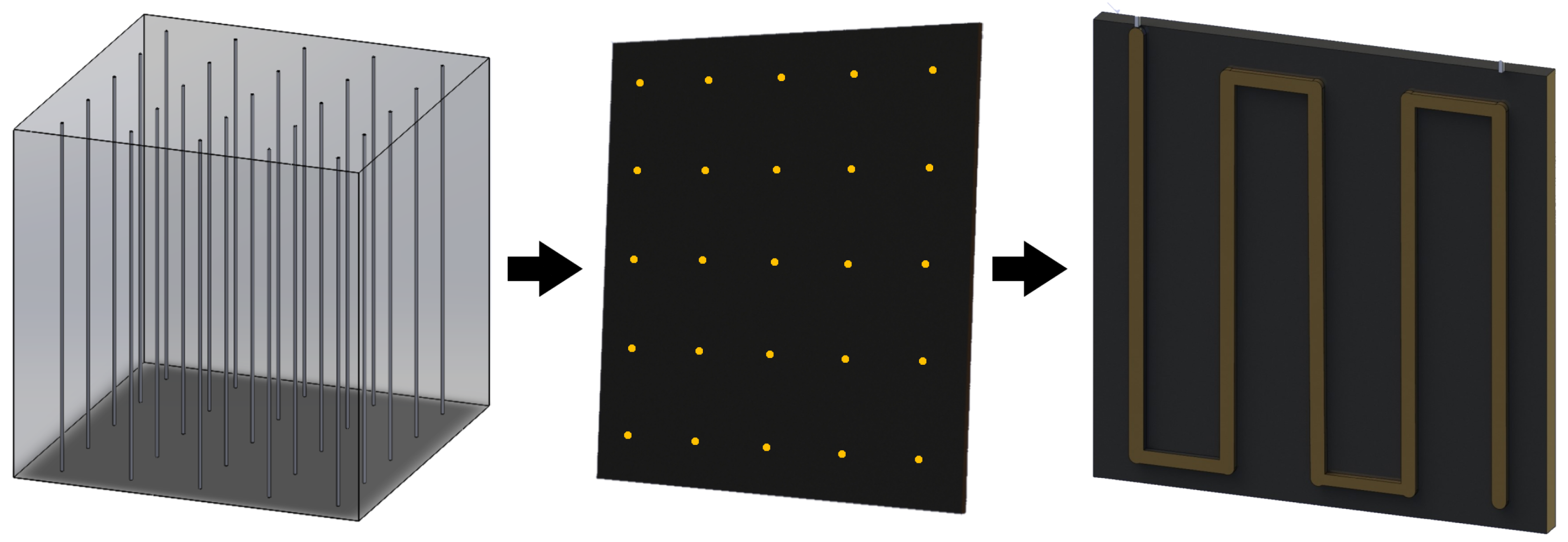
2.4. Composite Assembly

The final product of the high-energy ball milling process yielded cobalt ferrite nanoparticles for the development of magnetoelectric composites. To complete the composite structure, PZT-5A fibers were employed. A polyester resin—Thixotropic crystal polyester resin, based on dispersion with styrene monomer of viscosity 1.625 mPa·s (Advanced Vacuum), was employed. The liquid accelerator/catalyst utilized was Butanox—Methyl Ethyl Ketone Peroxide (Advanced Vacuum)—was utilized to bind the particles dispersed close to the PZT-5A fibers. The mass ratio of resin to composite was 100:1. The moderate viscosity resin-nanoparticles mixture was placed into an aluminum cubic mold (25 mm × 25 mm × 25 mm) with a lid featuring a perforated matrix with 25, 50, or 100 equidistant holes for the insertion of PZT fibers. The fibers were carefully inserted in the lid holes. To avoid bubbles, the resin curing process was kept under vacuum conditions. After the resin curing process (24 h), the cube composite was demolded, and 1 mm-thick cuts perpendicular to the PZT-5A fibers were made (a schematic drawing can be seen in Figure 1). The composite electrical connections (wiring schemes using silver ink to interconnect the PZT-5A fibers) are also shown in Figure 1. From this point, the composite is known as the sensor.

2.5. PZT Fibers Poling

The PZT fibers poling procedure utilized an experimental setup connected to a high-voltage source, PS375 System (Stanford Research, Sunnyvale, CA, USA). The poling process involved immersing the sensor in a beaker containing silicone, serving as a thermal energy conductor, to prevent potential electric discharges. The fibers were poled with an electric field perpendicularly to its circumference plane. The poling cycle was performed at 28 °C, using 3000 V and 3 μ A, until the PZT fibers achieved complete poling (1 h). These parameters were adopted based on the electrode connection type of the sensor, as previously described in the sensor fabrication section, and until the PZT fibers achieved complete poling.

2.6. Dielectric Permittivity and Dielectric Loss Tangent Measurements

Dielectric permittivity ( ε ) and dielectric loss tangent ( tan δ ) measurements were conducted at room temperature using an E4980A LCR meter (Agilent, Santa Clara, CA, USA), capable of measuring in the frequency range of 20 Hz to 2 MHz. The meter was connected to a computer for data acquisition.

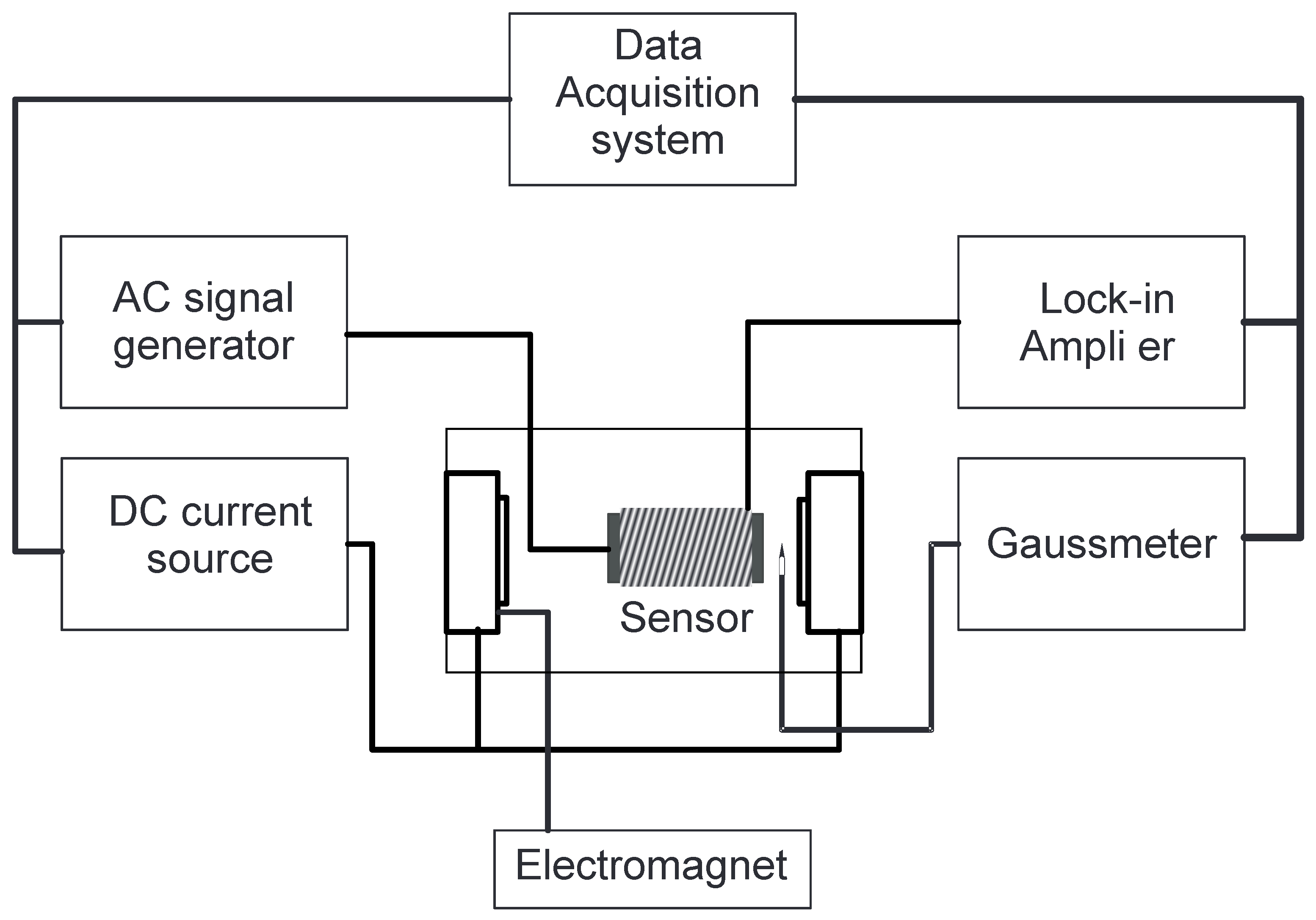
2.7. Magnetoelectric Measurements

A sample of magnetostrictive-piezoelectric phases is expected to be magnetoelectric since α E = δ P δ H is the product of the piezomagnetic deformation δ z δ H and the piezoelectric charge generation δ Q δ z [34].
To perform this measurement, we use a static magnetic field and a coil powered by a continuous voltage source. The voltage induced in the 25 PZT fiber sensor was measured using a voltmeter.
To determine the dynamic magnetoelectric coefficient, α E = δ V t δ H (where t is the composite thickness and δ H = H A C is the alternating magnetic field magnitude), experimental measurements were conducted, with a primary emphasis on the correlation between the electric and magnetic elements within the sensor implemented in this study. The configuration of the connections is illustrated in the schematic diagram shown in Figure 2, with the sensor placed at the center of the coil and equidistant to the poles of the electromagnet.
In line with the configuration illustrated in Figure 2, the sensor underwent exposure to a static magnetic field ( H D C ) produced by the electromagnet, ranging from 0 to 8 kOe. Within the coil, an attenuated field of 8 Oe, originating from an oscillating magnetic field ( H A C , f = 1 kHz), was employed. When operating in the in-plane orientation, both the H D C and H A C fields were applied in parallel to one another and parallel in relation to the sensor plane. Conversely, in the out-of-plane orientation, the H D C and H A C fields were employed parallel to each other but perpendicular to the sensor plane.
To oversee the magnitude of the magnetic field produced by the electromagnet ( H D C ), a gaussmeter was utilized with a Lakeshore 425 hall sensor-equipped probe (Lake Shore Cryotronics, Westerville, OH, USA). To monitor the voltage produced by the sensor, a SRS 830 lock-in amplifier (Stanford Research, Sunnyvale, USA) was implemented, which also functioned as a generator for the frequency while the alternating field H A C was applied.

3. Results and Discussion

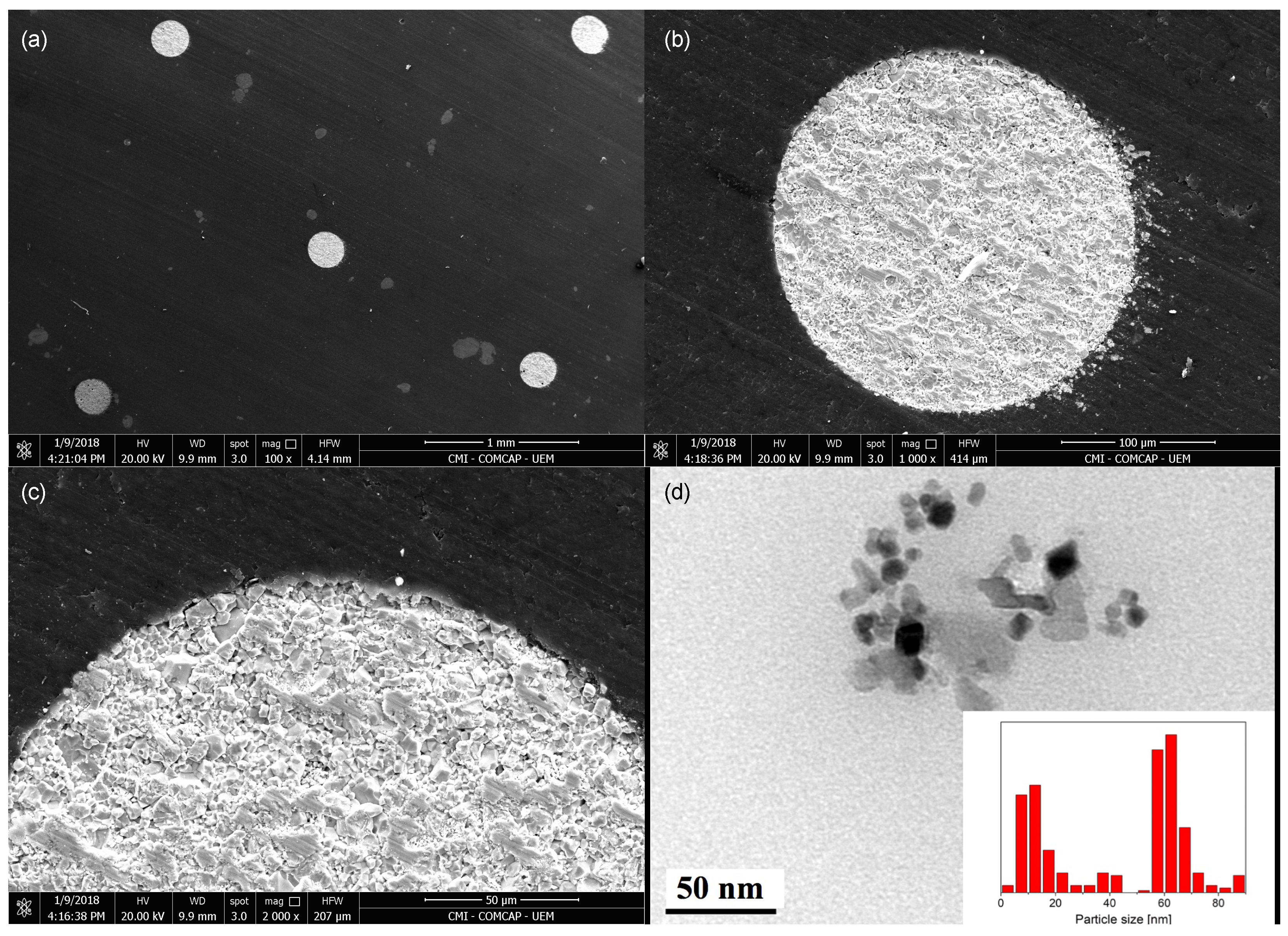
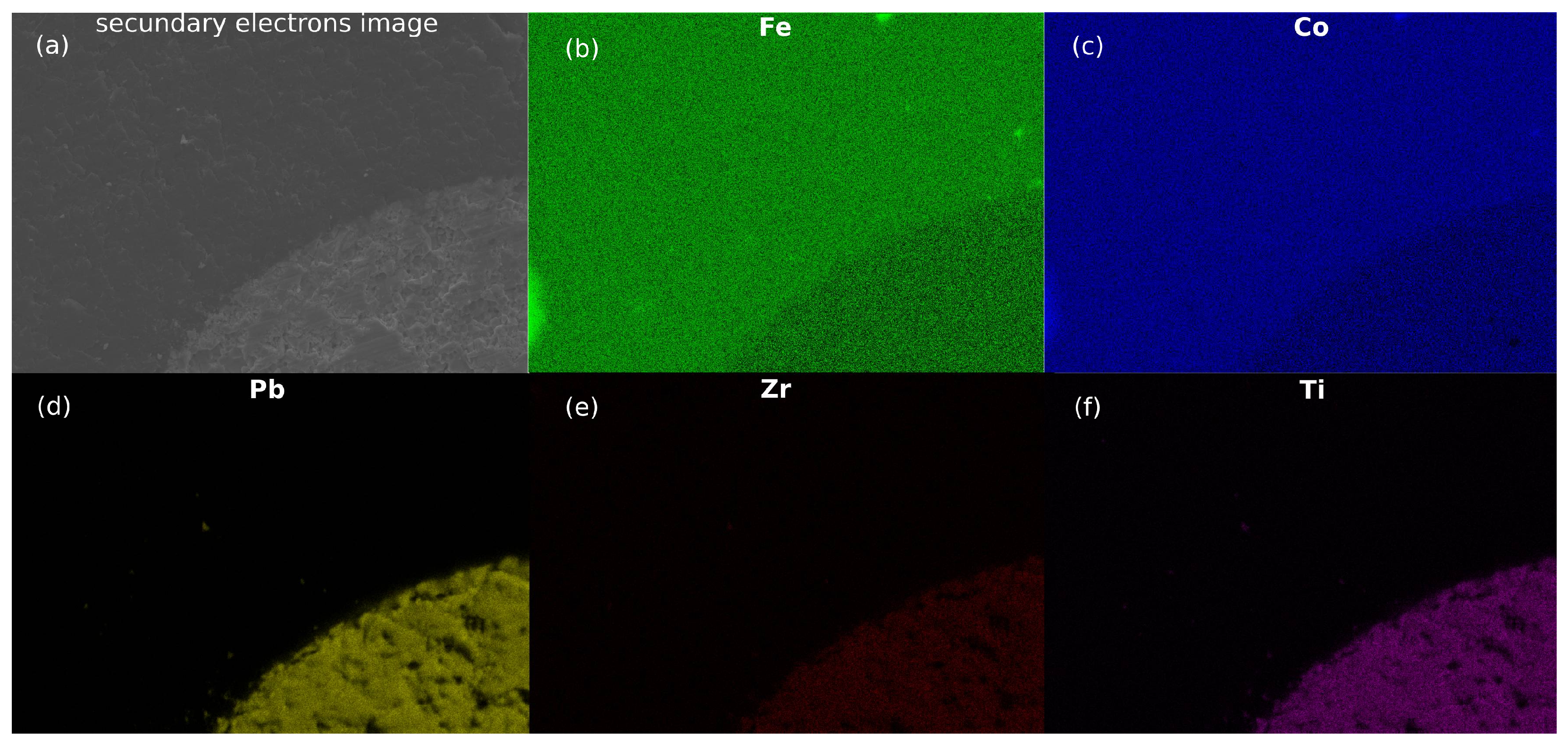
3.1. Electron Microscopy

Scanning electron microscopy images illustrate the composite’s microstructure with PZT-5A fibers embedded in the cobalt ferrite matrix (Figure 3). The fibers, depicted as clear circles, are uniformly distributed within the matrix (resin + cobalt ferrite), the darker portion (Figure 3a). A detailed view of the 250 μ m in diameter PZT-5A ceramic microfibers’ surface morphology can be seen in Figure 3b. The PZT-5A fiber surface shows the diversity of shapes and sizes of the constituent micro and nanoparticles. Additionally, an image of a fully inserted PZT-5A fiber within the matrix is presented in Figure 3c. The interface between the ceramic fibers and magnetic matrix merits attention, as it plays a pivotal role in determining the overall performance of the composite. Figure 3d illustrates a transmission electron microscopy image revealing the morphology of some cobalt ferrite nanoparticles, allowing the identification of geometries close to cubic shapes. The accompanying histogram in Figure 3d represents the grain size distribution, estimating the average size of the cobalt ferrite nanoparticles to be 10 nm.
Figure 4 shows the energy-dispersive X-ray spectroscopy (EDS) mapping of some elements in the overall image (Figure 4a) to verify the presence of iron (Figure 4b) and cobalt (Figure 4c) in the composite and, therefore, magnetic nanoparticles. In Figure 4d–f, the presence of characteristic chemical elements of the PZT-5A confirms the elemental composition of fibers. Thus, analysis by total EDS scanning of the composite reveals that magnetic nanoparticles are adhered to PZT fibers.

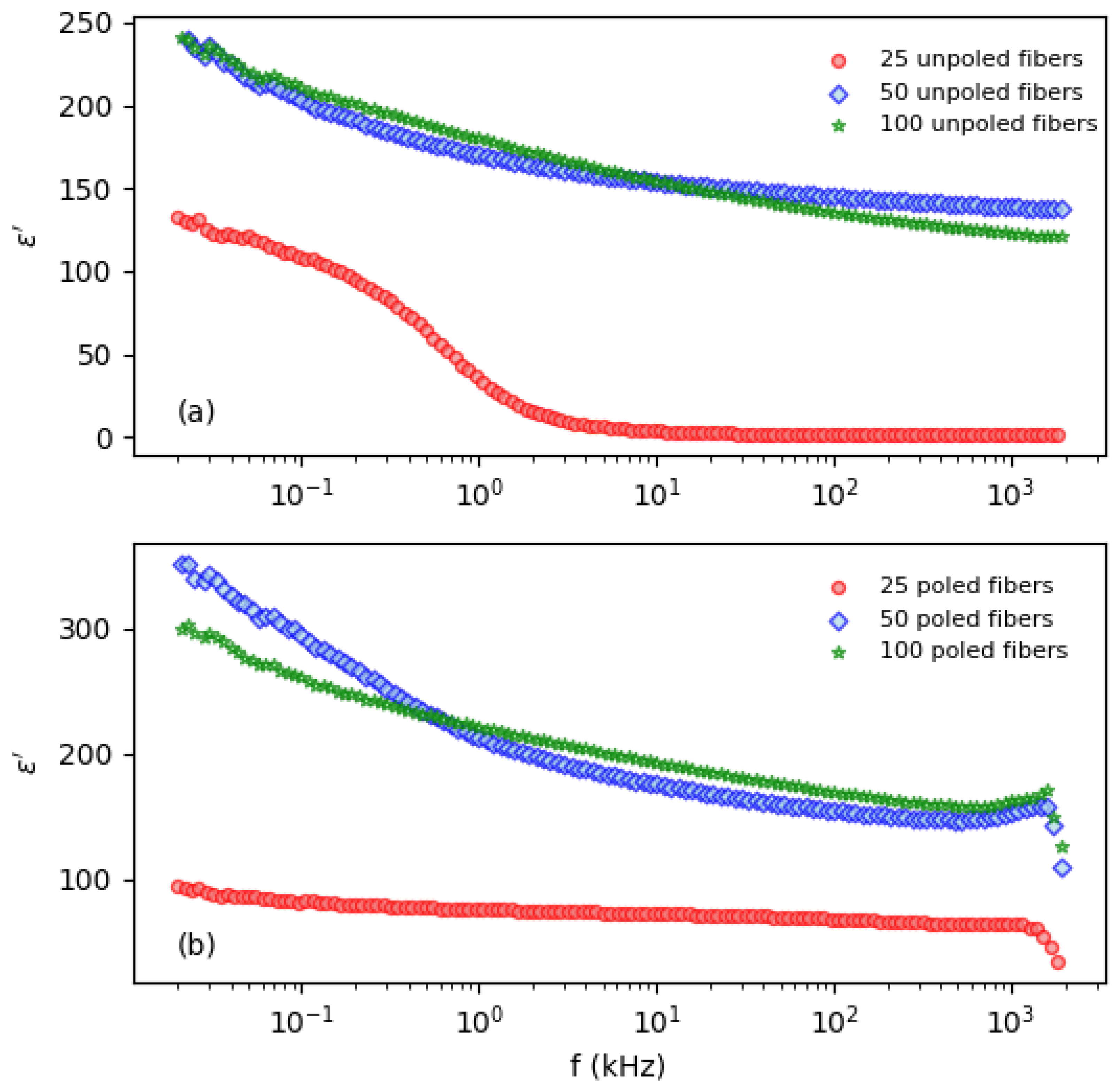
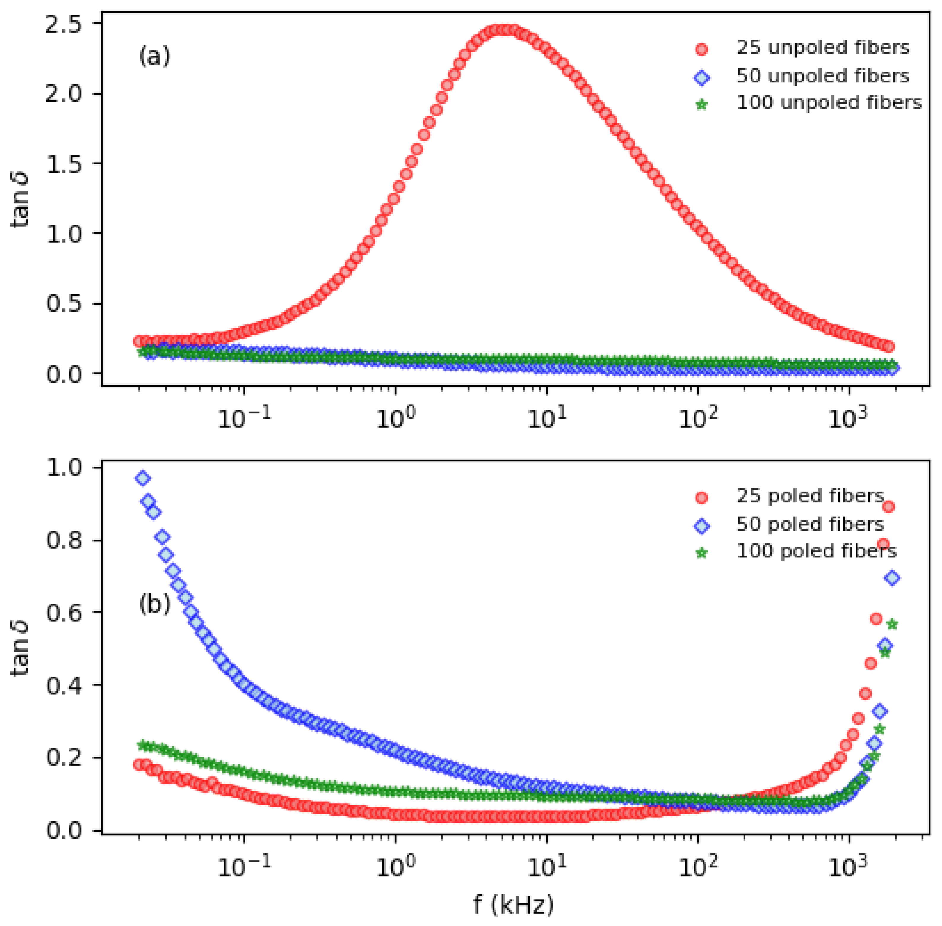
3.2. Dielectric Measurements

The dielectric permittivity ( ε ) measurements for both unpoled and poled fibers in the sensors are presented in Figure 5. For the sensor containing 25 unpoled fibers, the dielectric permittivity exhibits a decrease, starting from approximately 125 at 20 Hz and approaching nearly zero beyond 20 kHz. In contrast, the sensors with 50 and 100 unpoled fibers show a more gradual decrease in permittivity, dropping from around 250 at 20 Hz to approximately 150 at 2 MHz. When the fibers are poled (Figure 5b), the dielectric permittivity for the sensor with 25 fibers initially decreases slowly from around 100 at 20 Hz to about 60 at 1 MHz, after which it experiences a sharp decline. This trend is similarly observed in the other sensors, albeit with higher initial permittivity values. The observed behaviors indicate that poling significantly affects the dielectric properties, potentially enhancing the stability of dielectric permittivity at lower frequencies while altering the high-frequency response.
The dielectric loss tangent (tan δ ) exhibits distinct behaviors under different poling conditions (see Figure 6). Initially, at 20 Hz, the loss tangent is approximately 0.3 for both poled and unpoled fibers. In the sensor with 25 unpoled fibers, tan δ increases sharply, reaching around 2.5 at 5 kHz, followed by a decline to approximately 0.3 at 2 MHz. This peak is not observed in the sensors with 50 and 100 unpoled fibers. Conversely, for the poled fibers (see Figure 6b), the loss tangent remains relatively stable around 0.3 for the sensors with 20 and 50 poled fibers up to approximately 1 MHz, after which it begins to increase rapidly. These findings suggest that, within the studied frequency range, the sensor exhibits more stable dielectric properties, including both the dielectric constant and loss tangent, when the PZT-5A fibers are properly poled.
In fact, the dielectric properties of magnetoelectric (ME) composites have been extensively studied across various configurations, including 0–3 and 2–2 composites, where connectivity and composition significantly influence performance. The dielectric permittivity of ME composites typically decreases with increasing frequency, a widely reported phenomenon. For instance, Li et al. [35] noted that in 0–3 CFO-PZT composites, the dielectric permittivity decreases monotonically with decreasing CFO content and increasing frequency. This trend is attributed to the superior conductivity of CFO compared to PZT, resulting in more carriers in CFO that contribute to polarization under an applied electric field. At lower frequencies, all polarization mechanisms contribute to a higher dielectric constant, but as the frequency increases, these mechanisms cannot keep pace, leading to a reduction in ε . In contrast, our 1–3 ME composite exhibited an inverse relationship, where an increase in the PZT fibers number (and consequently fewer CFO nanoparticles) corresponded to a higher dielectric constant. Similarly, Peng et al. [36] reported a rapid decrease in ε with frequency in PZT-CFO composites, attributed to the dipole relaxation process and Maxwell-Wagner-type interfacial polarization. At higher frequencies, the dielectric permittivity saturates due to electronic displacement and ionic polarization, which require a shorter time for the polarization process. The stronger space charge polarization in composites with higher CFO content leads to higher ε at low frequencies. As shown in our study, the dielectric permittivity of 1–3 connectivity ME sensors exhibits a similar frequency-dependent behavior (Figure 5).
The dielectric loss tangent also exhibits frequency dependence, typically decreasing with increasing frequency. In 0–3 composites, the dielectric loss decreases at low frequencies and stabilizes at higher frequencies. This behavior can be linked to the relaxation polarization mechanisms, where mobile charge carriers, such as electrons, are unable to follow the high-frequency alternating electric field, thus reducing dielectric loss at high frequencies. Lu et al. [37] noted a similar trend in their study of PZT-CFO composites, where the relative permittivity and tan δ showed relaxor-like behavior with peaks shifting with frequency.
Our measurements suggest that the dielectric loss in our composites exhibits a similar pattern for the 50 and 100 unpoled fibers composite (Figure 6a), with higher values at low frequencies attributable to space charge polarization, followed by a decrease at higher frequencies. However, the 25 unpoled fibers composite and all the poled fibers composites display distinct behavior, indicating the possibility of phase transitions occurring within these compositions. Further detailed studies are required to elucidate the underlying mechanisms fully.
In particular, for the 25 PZT fibers sensor, the behavior observed for dielectric permittivity and dielectric loss tangent can be associated with the order-disorder dielectric transition typically observed in various ferroelectric materials with perovskite structure, particularly focusing on the physical mechanisms underlying the strain-induced order-disorder phase transition. Thus, our analysis revealed a strain-mediated pathway for this transition, particularly evident in the PZT system, which introduces an additional source of strain. It was observed that the magnitude of local distortions within the order–disorder crystal fluctuates due to elastic interactions, highlighting the dynamic nature of the transition.
Despite the lack of some information, we can propose that the dielectric measurements of our 1–3 ME composites reveal typical frequency-dependent behavior with high dielectric constant and loss at low frequencies due to space charge and interfacial polarization, decreasing at higher frequencies due to dipole relaxation processes. However, further investigation is necessary to fully understand these phenomena and their dependence on the composite’s microstructure and composition.
It is interesting to note that the loss tangent, which is associated with the energy loss during the alignment of electric dipoles during the poling process, it is expected that the sensor will exhibit a lower value of this quantity. This factor may directly interfere with the sensor’s sensitivity, as the loss tangent is also linked to the generation of noise in the internal structure of the sensor, impacting its sensitivity [38]. Finally, despite the lack of some information, we can propose that the dielectric measurements of our 1–3 ME sensors reveal typical frequency-dependent behavior with higher dielectric permittivity and loss at low frequencies due to space charge and interfacial polarization, decreasing at higher frequencies due to dipole relaxation processes. However, further investigation is necessary to fully understand these phenomena and their dependence on the composite’s microstructure and composition.

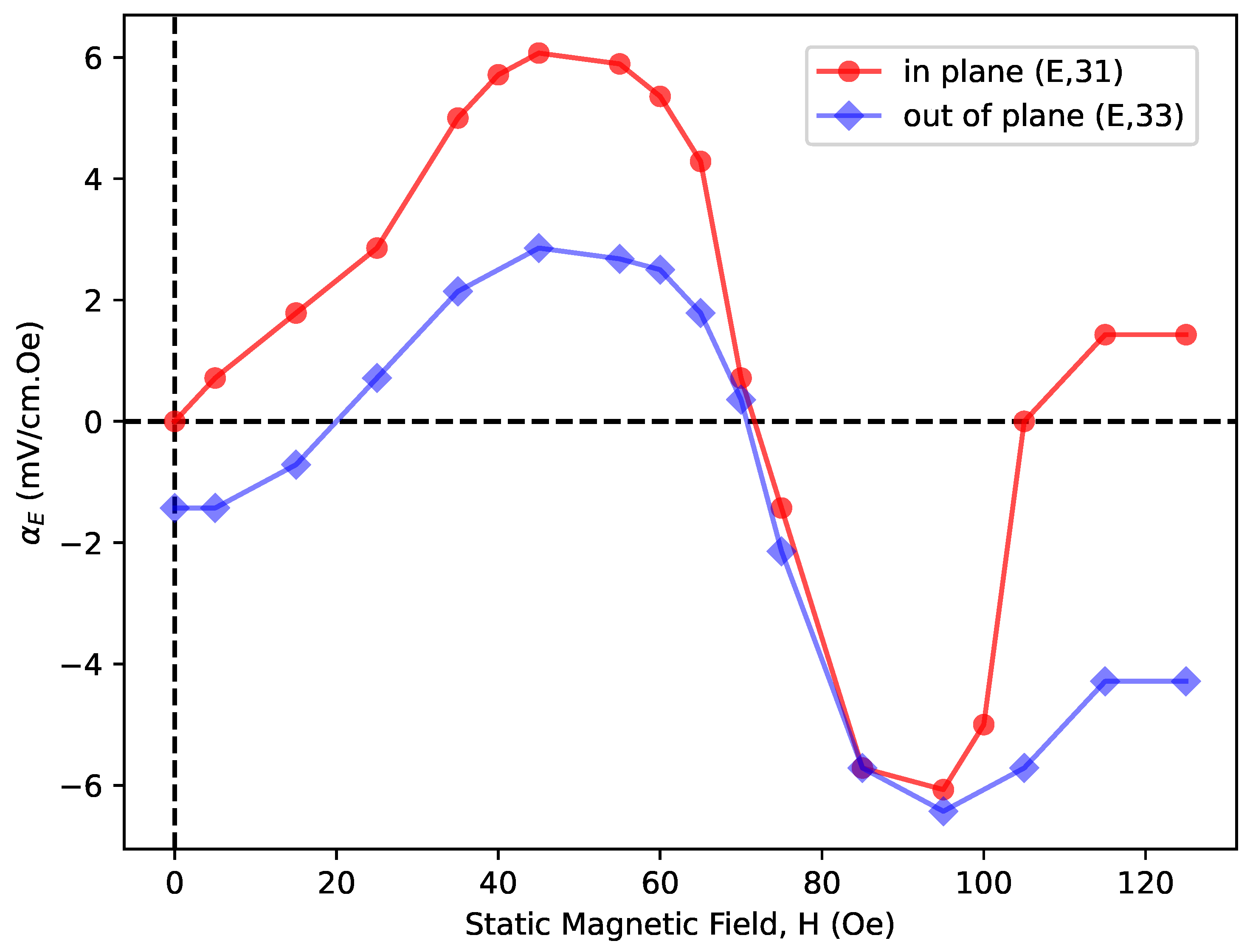
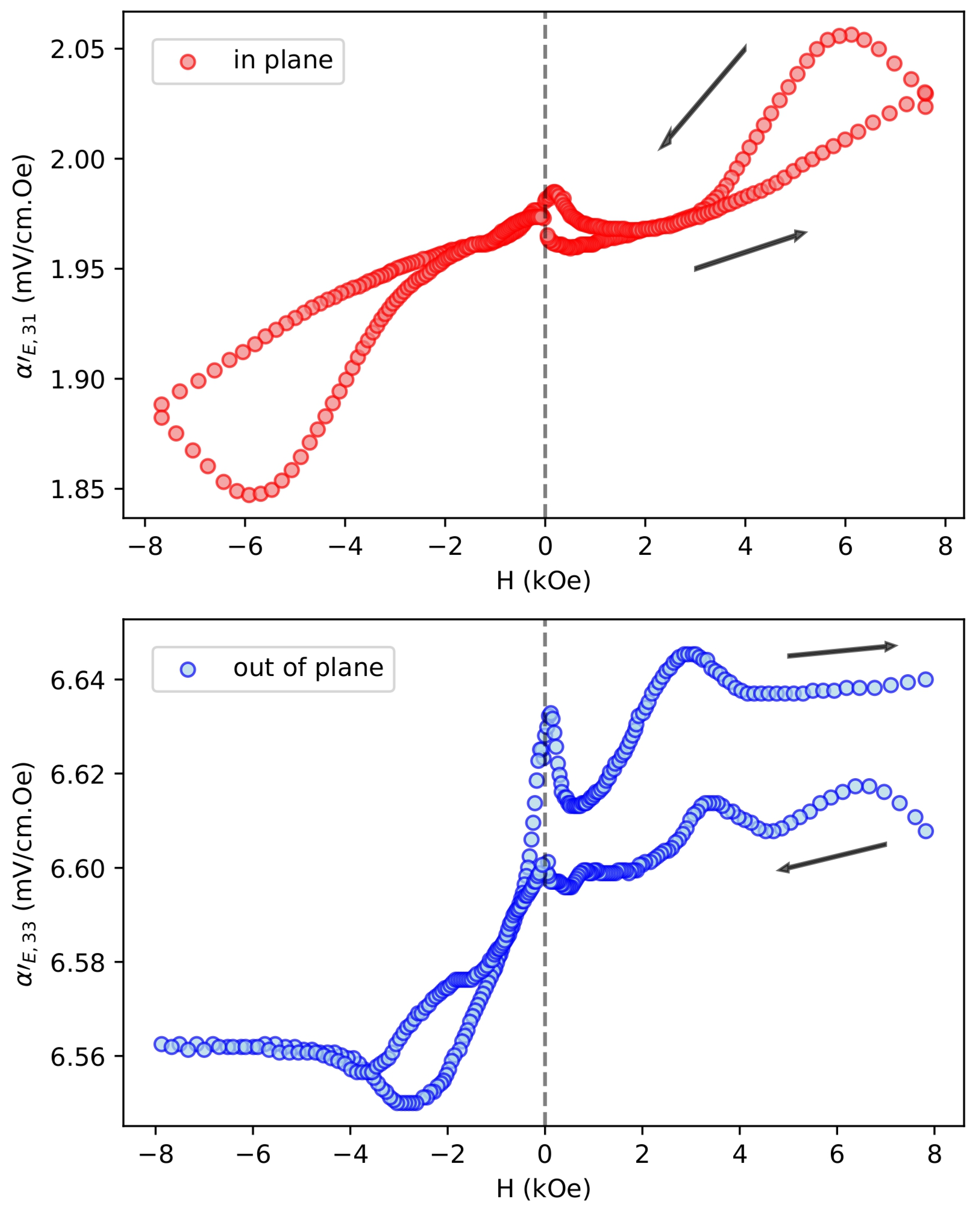
3.3. Magnetoelectric Measurements

Considering the dielectric measurement findings, we decide to study the magnetoelectric properties of the 25-poled fiber sensor. The results regarding the H-dependence of α E are illustrated in Figure 7. Strong ME interactions are observable, and the data from both scenarios indicated a comparable pattern. The coefficient associated with the out-of-plane arrangement exhibited a strength that was twice weaker (until ~50 Oe) than the in-plane orientation. The ME voltage coefficient for the in-plane case is expected to be greater than that of the out-of-plane case. This is why, when a material is subjected to a static magnetic field, its length changes, a phenomenon known as magnetostriction [34], i.e., causes a static deformation in response to a magnetic poling field H. As a consequence, the in-plane case leads to a higher length change effect.
Figure 8 show the data on H D C dependence of α E at room temperature. Interactions between magnetoelectric materials are evident, where distinct hysteresis and remanence phenomena can be observed. An increase in α E with H D C to a maximum value is observed, followed by a drop at a high field. The coefficients are directly proportional to the piezomagnetic coupling q   =   δ λ δ H , where λ is the magnetostriction, and the H-dependence tracks the slope of λ vs. H. Saturation of λ at high field leads to α E decrease. For most ferrites, λ out - of - plane = 2 λ in - plane [39] and one expects α E , 33 = 2 α E , 31 . One observes a doubling of peak ME voltage coefficient for out-of-plane cases compared to in-plane.
In summary, in the measurements shown in Figure 8, it is possible to observe that the values of α E are always greater than zero. This happens because the residual stress/strain has caused a bias in magnetoelectric measurements. The differences in the curves from the beginning to the end of the measurement are probably due to the fact that some residual stress/strain in the magnetostrictive component was released after the biased magnetic field application.
As we have been discussing, the magnetoelectric properties of ME composite materials play a crucial role in various applications, including sensors, actuators, and energy-harvesting devices. However, it is difficult to find ME composites and measurements in the same configurations for comparisons. Keeping this fact in mind, here we discuss the ME measurement results from some studies in the literature, comparing their findings with our observations. Peng et al. [36] investigated ME composites composed of PZT and CFO powders in different proportions. They observed the ME voltage coefficient as a function of frequency for a 0–3 PZT-CFO composite sintered under a biased magnetic field. The maximum value of the ME coefficient in the PZT-CFO composite reached 226 mV/cm·Oe at a frequency of 75.1 kHz (the mechanical resonance condition). This finding suggests a strong magnetoelectric coupling in the composite. Lu et al. [37] investigated ME composites with varying compositions of PZT and CFO. They observed the ME coefficient as a function of DC magnetic bias and AC frequency. Their results indicated that the ME coefficients increased with increasing DC bias for all samples, suggesting an enhanced coupling between magnetostriction in CFO and piezoelectric response in PZT. At a frequency of 100 kHz, the maximum ME coefficient reached 32 mV/cm·Oe, ten times larger than that obtained at 1 kHz for a DC bias of 2 kOe. This observation highlights the importance of DC bias in modulating the ME response and suggests the potential for further enhancement at resonance frequencies.
Lam et al. [40] fabricated ME composites consisting of PZT rods embedded in a matrix of Terfenol-D/epoxy 1–3 composites. They investigated the ME effect at 1 kHz and observed a monotonic increase in the ME coefficient with increasing magnetic bias. At 2 kOe, the ME coefficient value approached 130 mV/cm·Oe, significantly higher than that reported for ME particulate composites. This result underscores the importance of composite design and microstructure in achieving enhanced magnetoelectric coupling.
Overall, the ME measurement results from these studies demonstrate the significant influence of composition, microstructure, and external factors, such as DC magnetic bias, on the magnetoelectric properties of composites. Our findings corroborate and extend these observations, highlighting the potential of ME composites for various technological applications. Actually, the more significant finding that emerges from our study is that the collective results suggest successful fabrication and integration of magnetic nanoparticles and PZT ceramic microfibers. The dielectric and magnetoelectric responses are promising, indicating the potential suitability of the composite for applications in sensors or medical devices.
Further studies may explore optimizing the composite composition for enhanced magnetoelectric coupling, mainly for further enhancement at resonance frequencies. Investigate the long-term stability and reliability of the composites under varying environmental conditions.

4. Conclusions

In conclusion, this study has successfully developed a cost-effective and straightforward method for fabricating a magnetoelectric composite comprising PZT fibers, cobalt (CoFe2O4), and a polymeric resin. Unlike previous methods, which often resulted in complex and expensive preparations with unfavorable properties, this approach offers a facile assembly process at room temperature, maintaining the original properties of the components and avoiding unwanted phases.
The scanning electron microscopy images demonstrate the uniform distribution of PZT-5A fibers within the cobalt matrix, with a detailed view revealing diverse surface morphologies of the ceramic microfibers. The interface between the fibers and the magnetic matrix is crucial for determining overall performance, as demonstrated by transmission electron microscopy images showing cobalt grain size distribution and X-ray spectroscopy mapping confirming the elemental composition.
Dielectric measurements reveal stable behavior in the composites, particularly when PZT-5A fibers are properly poled, suggesting potential applications in sensors or medical devices. The observed hysteresis and phenomena in H-dependence further highlight strong magnetoelectric interactions, with promising indications for enhancing coupling efficiency and peak ME voltage coefficient.
Overall, this study lays the groundwork for future investigations aimed at optimizing composite composition, assessing long-term stability, and exploring potential applications in various fields, including intelligent sensors and electronic components. Further research in these areas will contribute to advancing the understanding and utilization of magnetoelectric composites in diverse technological applications.

Author Contributions

Conceptualization, R.G., A.S.B. and L.F.C.; Methodology, R.G. and A.S.B. and L.F.C.; Validation, R.G. and A.S.B.; Formal analysis, L.N.P. and J.C.A.P.; Investigation, L.N.P., J.C.A.P. and G.S.D.; Writing—original draft, L.N.P. and L.F.C.; Writing—review & editing, G.S.D., I.A.d.S., R.G. and A.S.B.; Supervision, A.S.B. and L.F.C.; Project administration, L.F.C. All authors have read and agreed to the published version of the manuscript.

Funding

This research was funded by Financiadora de Estudos e Projetos (Finep); Conselho Nacional de Desenvolvimento Científico e Tecnológico (CNPq); Coordenação de Aperfeiçoamento de Pessoal de Nível Superior (CAPES) and Fundação Araucária.

Data Availability Statement

The data presented in this study are available in this article.

Acknowledgments

The authors would like to thank the Microscopy Center of the Research Support Center Complex (COMCAP/UEM) and funding agencies for providing financial support to carry out the experimental work.

Conflicts of Interest

The authors declare no conflict of interest.

References

  1. Spaldin, N.A.; Fiebig, M. The renaissance of magnetoelectric multiferroics. Science 2005, 309, 391–392. [Google Scholar] [CrossRef]
  2. Schmid, H. Multi-ferroic magnetoelectrics. Ferroelectrics 1994, 162, 317–338. [Google Scholar] [CrossRef]
  3. Nan, C.W.; Bichurin, M.I.; Dong, S.; Viehland, D.; Srinivasan, G. Multiferroic magnetoelectric composites: Historical perspective, status, and future directions. J. Appl. Phys. 2008, 103, 031101. [Google Scholar] [CrossRef]
  4. Pradhan, D.K.; Kumari, S.; Rack, P.D. Magnetoelectric Composites: Applications, Coupling Mechanisms, and Future Directions. Nanomaterials 2020, 10, 2072. [Google Scholar] [CrossRef]
  5. Rafique, M.; ul Hassan, S.Q.; Awan, M.S.; Manzoor, S. Dependence of magnetoelectric properties on the magnetostrictive content in 0–3 composites. Ceram. Int. 2013, 39, 213–216. [Google Scholar] [CrossRef]
  6. Getman, I. Magnetoelectric composite materials: Theoretical approach to determine their properties. Ferroelectrics 1994, 162, 45–50. [Google Scholar] [CrossRef]
  7. Katayama, T.; Yasui, S.; Hamasaki, Y.; Shiraishi, T.; Akama, A.; Kiguchi, T.; Itoh, M. Ferroelectric and Magnetic Properties in Room-Temperature Multiferroic GaxFe2−xO3 Epitaxial Thin Films. Adv. Funct. Mater. 2017, 28, 1704789. [Google Scholar] [CrossRef]
  8. Chu, Z.; PourhosseiniAsl, M.; Dong, S. Review of multi-layered magnetoelectric composite materials and devices applications. J. Phys. Appl. Phys. 2018, 51, 243001. [Google Scholar] [CrossRef]
  9. Wang, Y.; Hu, J.; Lin, Y.; Nan, C.W. Multiferroic magnetoelectric composite nanostructures. NPG Asia Mater. 2010, 2, 61–68. [Google Scholar] [CrossRef]
  10. Kopyl, S.; Surmenev, R.; Surmeneva, M.; Fetisov, Y.; Kholkin, A. Magnetoelectric effect: Principles and applications in biology and medicine—A review. Mater. Today Bio 2021, 12, 100149. [Google Scholar] [CrossRef]
  11. Leung, C.M.; Li, J.; Viehland, D.; Zhuang, X. A review on applications of magnetoelectric composites: From heterostructural uncooled magnetic sensors, energy harvesters to highly efficient power converters. J. Phys. D Appl. Phys. 2018, 51, 263002. [Google Scholar] [CrossRef]
  12. Nan, C.W. Magnetoelectric effect in composites of piezoelectric and piezomagnetic phases. Phys. Rev. B Condens. Matter 1994, 50, 6082–6088. [Google Scholar] [CrossRef]
  13. Lopatin, S.; Lopatina, I.; Lisnevskaya, I. Magnetoelectric PZT/ferrite composite material. Ferroelectrics 1994, 162, 63–68. [Google Scholar] [CrossRef]
  14. Ryu, J.; Carazo, A.V.; Uchino, K.; Kim, H.E. Magnetoelectric properties in piezoelectric and magnetostrictive laminate composites. Jpn. J. Appl. Phys. 2001, 40, 4948. [Google Scholar] [CrossRef]
  15. Cho, K.H.; Bichurin, M.I.; Petrov, V.M.; Bhalla, A.; Priya, S. Magnetoelectric laminate composite: Effect of piezoelectric layer on magnetoelectric properties. Ferroelectrics 2014, 473, 110–128. [Google Scholar] [CrossRef]
  16. Tian, R.; Liu, J.; Liu, X. Magnetoelectric properties of piezoelectric-piezomagnetic composites with elliptical nanofibers. Acta Mech. Solida Sin. 2020, 33, 368–380. [Google Scholar] [CrossRef]
  17. Bichurin, M.; Petrov, V. Modeling of Magnetoelectric Effects in Composites; Springer: Dordrecht, The Netherlands, 2014. [Google Scholar] [CrossRef]
  18. Elzenheimer, E.; Bald, C.; Engelhardt, E.; Hoffmann, J.; Hayes, P.; Arbustini, J.; Bahr, A.; Quandt, E.; Höft, M.; Schmidt, G. Quantitative Evaluation for Magnetoelectric Sensor Systems in Biomagnetic Diagnostics. Sensors 2022, 22, 1018. [Google Scholar] [CrossRef]
  19. Jahns, R.; Knochel, R.; Greve, H.; Woltermann, E.; Lage, E.; Quandt, E. Magnetoelectric sensors for biomagnetic measurements. In Proceedings of the 2011 IEEE International Symposium on Medical Measurements and Applications, Bari, Italy, 30–31 May 2011; IEEE: Piscataway, NJ, USA, 2011. [Google Scholar] [CrossRef]
  20. Elzenheimer, E.; Hayes, P.; Thormählen, L.; Engelhardt, E.; Zaman, A.; Quandt, E.; Frey, N.; Höft, M.; Schmidt, G. Investigation of Converse Magnetoelectric Thin-Film Sensors for Magnetocardiography. IEEE Sens. J. 2023, 23, 5660–5669. [Google Scholar] [CrossRef]
  21. Gao, J.; Wang, Y.; Li, M.; Shen, Y.; Li, J.; Viehland, D. Quasi-static (f<10−2Hz) frequency response of magnetoelectric composites based magnetic sensor. Mater. Lett. 2012, 85, 84–87. [Google Scholar]
  22. Duc, N.H.; Giang, D.T.H. Magnetic sensors based on piezoelectric-magnetostrictive composites. J. Alloys Compd. 2008, 449, 214–218. [Google Scholar] [CrossRef]
  23. Klug, M.J.; Thormählen, L.; Röbisch, V.; Toxværd, S.D.; Höft, M.; Knöchel, R.; Quandt, E.; Meyners, D.; McCord, J. Antiparallel exchange biased multilayers for low magnetic noise magnetic field sensors. Appl. Phys. Lett. 2019, 114, 192410. [Google Scholar] [CrossRef]
  24. Hu, J.M.; Nan, T.; Sun, N.X.; Chen, L.Q. Multiferroic magnetoelectric nanostructures for novel device applications. MRS Bull. 2015, 40, 728–735. [Google Scholar] [CrossRef]
  25. Hu, J.M.; Nan, C.W. Opportunities and challenges for magnetoelectric devices. APL Mater. 2019, 7, 080905. [Google Scholar] [CrossRef]
  26. Nan, T.; Lin, H.; Gao, Y.; Matyushov, A.; Yu, G.; Chen, H.; Sun, N.; Wei, S.; Wang, Z.; Li, M.; et al. Acoustically actuated ultra-compact NEMS magnetoelectric antennas. Nat. Commun. 2017, 8, 296. [Google Scholar] [CrossRef]
  27. Jiang, L.; Yang, Y.; Chen, R.; Lu, G.; Li, R.; Li, D.; Humayun, M.S.; Shung, K.K.; Zhu, J.; Chen, Y.; et al. Flexible piezoelectric ultrasonic energy harvester array for bio-implantable wireless generator. Nano Energy 2019, 56, 216–224. [Google Scholar] [CrossRef]
  28. Kuts, V.V.; Turutin, A.V.; Kislyuk, A.M.; Kubasov, I.V.; Maksumova, E.E.; Temirov, A.A.; Malinkovich, M.D.; Sobolev, N.A.; Parkhomenko, Y.N. Detection of inhomogeneous magnetic fields using magnetoelectric composites. Mod. Electron. Mater. 2023, 9, 105–113. [Google Scholar] [CrossRef]
  29. Turutin, A.V.; Kubasov, I.V.; Kislyuk, A.M.; Kuts, V.V.; Malinkovich, M.D.; Parkhomenko, Y.N.; Sobolev, N.A. Ultra-sensitive magnetoelectric sensors of magnetic fields for biomedical applications. Nanotechnol. Russ. 2022, 17, 261–289. [Google Scholar] [CrossRef]
  30. Liang, X.; Matyushov, A.; Hayes, P.; Schell, V.; Dong, C.; Chen, H.; He, Y.; Will-Cole, A.; Quandt, E.; Martins, P.; et al. Roadmap on Magnetoelectric Materials and Devices. IEEE Trans. Magn. 2021, 57, 1–57. [Google Scholar] [CrossRef]
  31. Plyushch, A.; Lewin, D.; Sokal, A.; Grigalaitis, R.; Shvartsman, V.V.; Macutkevič, J.; Salamon, S.; Wende, H.; Lapko, K.N.; Kuzhir, P.P.; et al. Magnetoelectric coupling in nonsintered bulk BaTiO3−xCoFe2O4 multiferroic composites. J. Alloys Compd. 2022, 917, 165519. [Google Scholar] [CrossRef]
  32. Plyushch, A.; Lewin, D.; Ažubalis, P.; Kalendra, V.; Sokal, A.; Grigalaitis, R.; Shvartsman, V.V.; Salamon, S.; Wende, H.; Selskis, A.; et al. Phosphate bonded CoFe2O4–BaTiO3 layered structures: Dielectric relaxations and magnetoelectric coupling. Lith. J. Phys. 2022, 62, 221–228. [Google Scholar] [CrossRef]
  33. Gao, R.; Zhang, Q.; Xu, Z.; Wang, Z.; Chen, G.; Fu, C.; Deng, X.; Cai, W. Anomalous Magnetoelectric Coupling Effect of CoFe2O4–BaTiO3 Binary Mixed Fluids. ACS Appl. Electron. Mater. 2019, 1, 1120–1132. [Google Scholar] [CrossRef]
  34. Srinivasan, G. Magnetoelectric Composites. Annu. Rev. Mater. Res. 2010, 40, 153–178. [Google Scholar] [CrossRef]
  35. Li, C.; Xu, R.; Gao, R.; Wang, Z.; Chen, G.; Deng, X.; Cai, W.; Fu, C.; Li, Q. A comparative study on the structural, dielectric, ferroelectric and magnetic properties of CoFe2O4/PbZr0.52Ti0.48O3 multiferroic composite with different molar ratios. J. Phys. Commun. 2019, 3, 125010. [Google Scholar] [CrossRef]
  36. Peng, J.-H.; Hojamberdiev, M.; Li, H.-Q.; Mao, D.-L.; Zhao, Y.-J.; Liu, P.; Zhou, J.-P.; Zhu, G.-Q. Electrical, magnetic, and direct and converse magnetoelectric properties of (1 − x)Pb(Zr0.52Ti0.48)O3 − (x)CoFe2O4 (PZT–CFO) magnetoelectric composites. J. Magn. Magn. Mater. 2015, 378, 298–305. [Google Scholar] [CrossRef]
  37. Lu, S.G.; Xu, Z.K.; Wang, Y.P.; Guo, S.S.; Chen, H.; Li, T.L.; Or, S.W. Effect of CoFe2O4 content on the dielectric and magnetoelectric properties in Pb(ZrTi)O3/CoFe2O4 composite. J. Electroceram. 2007, 21, 398–400. [Google Scholar] [CrossRef]
  38. Gao, J.; Jiang, Z.; Zhang, S.; Mao, Z.; Shen, Y.; Chu, Z. Review of Magnetoelectric Sensors. Actuators 2021, 10, 109. [Google Scholar] [CrossRef]
  39. Laletin, V.M.; Srinivasan, G. Magnetoelectric Effects in Composites of Nickel Ferrite and Barium Lead Zirconate Titanate. Ferroelectrics 2002, 280, 177–185. [Google Scholar] [CrossRef]
  40. Lam, K.H.; Lo, C.Y.; Chan, H.L.W. Frequency response of magnetoelectric 1–3-type composites. J. Appl. Phys. 2010, 107. [Google Scholar] [CrossRef]
Figure 1. The cube composite, 1 mm-thick cuts perpendicular to the PZT-5A fibers, and the composite electrical connections (wiring schemes using silver ink to interconnect the PZT-5A fibers).
Electronics 13 02266 g001
Figure 2. Schematic diagram of a magnetoelectric measurement system, with the sensor placed at the center of the coil and equidistant to the poles of the electromagnet.
Electronics 13 02266 g002
Figure 3. Scanning electron microscopy analyses of the composite: (a) fibers are uniformly distributed within the matrix (resin + cobalt ferrite), (b) a detailed view of the 250 μ m in diameter PZT-5A fiber, (c) fully inserted PZT-5A fiber within the matrix. (d) Transmission electron microscopy image of CoFe2O4 nanoparticles.
Electronics 13 02266 g003
Figure 4. Chemical elements mapping using energy-dispersive X-ray spectroscopy (EDS) on a selected area from the sensor.
Electronics 13 02266 g004
Figure 5. Dielectric permittivity measurements for both unpoled and poled 25, 50, and 100 fibers in the sensor.
Electronics 13 02266 g005
Figure 6. Dielectric loss tangent measurements for both unpoled and poled 25, 50, and 100 fibers in the sensor.
Electronics 13 02266 g006
Figure 7. Static magnetic field dependence of α E for the poled sensor.
Electronics 13 02266 g007
Figure 8. Magnetoelectric loops for the poled sensor.
Electronics 13 02266 g008
Disclaimer/Publisher’s Note: The statements, opinions and data contained in all publications are solely those of the individual author(s) and contributor(s) and not of MDPI and/or the editor(s). MDPI and/or the editor(s) disclaim responsibility for any injury to people or property resulting from any ideas, methods, instructions or products referred to in the content.

