Article

Control and Managing of Individual Solar Water Heating Systems in an Apartment Complex

Department of Electrical/Electronic Engineering, Ariel University, Ariel 40700, Israel
*
Author to whom correspondence should be addressed.
Electronics 2024, 13(12), 2305; https://doi.org/10.3390/electronics13122305
Submission received: 16 May 2024 / Revised: 8 June 2024 / Accepted: 11 June 2024 / Published: 13 June 2024
(This article belongs to the Special Issue Power Electronics and Renewable Energy System)

Abstract

:
Managing solar energy utilization and water heating in multi-apartment buildings presents formidable challenges due to limited space for solar collector installation. Optimizing heat energy distribution among communal consumers is crucial, necessitating precise regulation of hot water flow from the main system line to individual thermal storage tanks. The objective is to minimize heat and electricity losses while maximizing temperature levels in each tank. An electronic control system, centered around a microcontroller, has been developed with an efficient algorithm, data storage memory, and communication capabilities. The implemented solar heating system is tailored to each individual consumer, incorporating precise measurements for every apartment. This customization enhances efficiency not only for the individual consumer but also benefits the overall solar system within the building. This article explores the development and past outcomes of implementing such a control system, highlighting its significant advantages, particularly in multi-story buildings.

1. Introduction

The utilization of solar energy for water heating, both for individual consumers and those residing in multi-story buildings, stands as an effective technology aimed at reducing reliance on fossil fuels and electricity. Various authors in the cited works delve into different aspects of solar heating in domestic applications. Authors [1,2,3,4] provide comprehensive analyses of current technological and technical solutions for utilizing solar energy in water heating. They emphasize various technical approaches for water heating as well as for other thermal applications like air heating and cooking. Additionally, they delve into the marketing considerations associated with implementing solar heating solutions.
The authors of [5] explore various technical solutions aimed at enhancing the absorption of solar irradiation, optimizing the transition of thermal energy from solar collectors, and improving the thermal efficiency of storage tanks. These approaches include the utilization of carbon nanotubes, the application of special coatings on tubes, and the optimization of pump control for circulating hot coolant within the system.
Work [6] provides a collective study on enhancing energy efficiency and optimizing operations in solar water heating systems. Moreover, several works focus on analyzing the advantages of solar heating in specific domestic contexts. For instance, Ref. [7] examines solar thermal systems for domestic hot water technology in urban areas of Maputo city, Mozambique. The thorough analysis conducted for this specific geographic region revealed the potential for reducing reliance on electricity, which is notably expensive in this area. The authors underscore the potential reduction in CO2 emissions by 78.8% and a decrease in network electricity usage by 65.7%, respectively.
The research in [8] scrutinizes the efficiency of thermal energy storage in buildings situated in continental climatic zones whereas [9] conducts a similar analysis for various heating systems in residential buildings within Mediterranean climates. The research [10] explores this topic in the context of Lahore, Pakistan. The study in [10] was carried out by a special simulation software, approved the efficiency of a solar heating during all the seasons in a year in the Lahore area. In this context, it is noteworthy to mention that the prediction and analysis of solar heating systems’ functionality signify significant scientific and engineering interest.
The citations [11,12,13] present various methods for simulation, prediction, and design of solar heating appliances, particularly in smart buildings and for small-scale applications. Notably, Ref. [11] introduces a valuable random forest model based on a stochastic approach for predicting water solar heating performance that is a request of European standard [12]. The work [13] introduces a specialized algorithm utilizing ISIS-PROTEUS software to design a solar water heater control system, employing the PIC 16F877 microcontroller programmed with the PROTON programming language. Meanwhile, Ref. [14] presents a control mechanism for solar heating systems aimed at preventing excessive water temperature rise while ensuring a sufficient supply of hot water for individual households.
The references [15,16,17,18,19,20] explore various control and measurement techniques for solar water heating systems. In [15], a control model for solar water heating is established using a Programmable Logic Controller (PLC), which displays functionality results on a dedicated interface allowing for human–machine interaction. The work of [16] focuses on integrating Internet-of-Things (IoT) technologies into the physical system, incorporating elements such as a heat pump, photovoltaics, solar thermal panels, and an innovative low-enthalpy radiant wall and ceiling. This integration aims to achieve self-sufficient heating and cooling.
The research in [17] is dedicated to developing a measurement and control system for solar water heating engineering devices. It utilizes programmable logic controllers and industrial human–machine interfaces. Additionally, References [18,19] emphasize the utilization of IoT technologies, while [20] presents an enhanced solution for water temperature measurements.
A significant portion of the research delves into different algorithms and their implementation in control systems. References [21,22,23] provide validation and analysis of control efficiency, while [24] discusses the adaptive model approach and Reference [25] presents the inferential model-based predictive control. Furthermore, optimal control of a hybrid photovoltaic/thermal water system is demonstrated in [26].
The implementation of electronic appliances for water heating control is elaborated upon in references [27,28]. It is notable to highlight that the current trend in such control systems involves the integration of IoT approaches [16] and the transmission of measured data to dedicated Internet web pages.
Summarizing the scientific works discussed above, it is evident that significant progress has been made in the field of solar water heating systems. However, there has been insufficient emphasis and analysis on appliances in multi-story buildings to date. Furthermore, communication with Internet platforms remains a relatively uncommon option, thus hindering efficient monitoring, predictive control, and optimization of system functionality. Therefore, the novelty of our work lies in the development, evaluation, and assessment of a new technical solution based on an improved control algorithm incorporating more precise measurements of hot water temperature without the need for a built-in special sensor. Furthermore, by integrating telecommunication capabilities into the electronic board for transmitting measured data to a dedicated Internet page with high-time resolution (60 s), we enable continuous monitoring and rigorous analysis of the system’s functionality. This, in turn, facilitates the implementation of additional Artificial Intelligence (AI) control, optimized for adapting to changing environmental conditions and the aging of solar collectors.
The article is structured as follows: after the Introduction, Section 2 presents the conventional and revised solar water heating system in multi-story buildings, analyzing the drawbacks of existing appliances and proposing solutions to address them. Additionally, Section 2 outlines the algorithm of the new design and its implementation in the electronic circuit and board design. Section 3, based on collected measurements, discusses the Results of the experimental operation of the new individual solar heating appliance and the monitoring system. Finally, Section 4 offers the Discussion and Conclusion of the proposed monitoring system.

2. Methods

This section presents an analysis of a conventional solar heating system in multi-story buildings, highlighting its limitations and underscoring the necessity for modernization. Subsequently, the primary solution involving the enhanced individual solar appliance is outlined. Furthermore, the control algorithm, its integration into the electronic circuit, and the system’s design are elaborated upon.

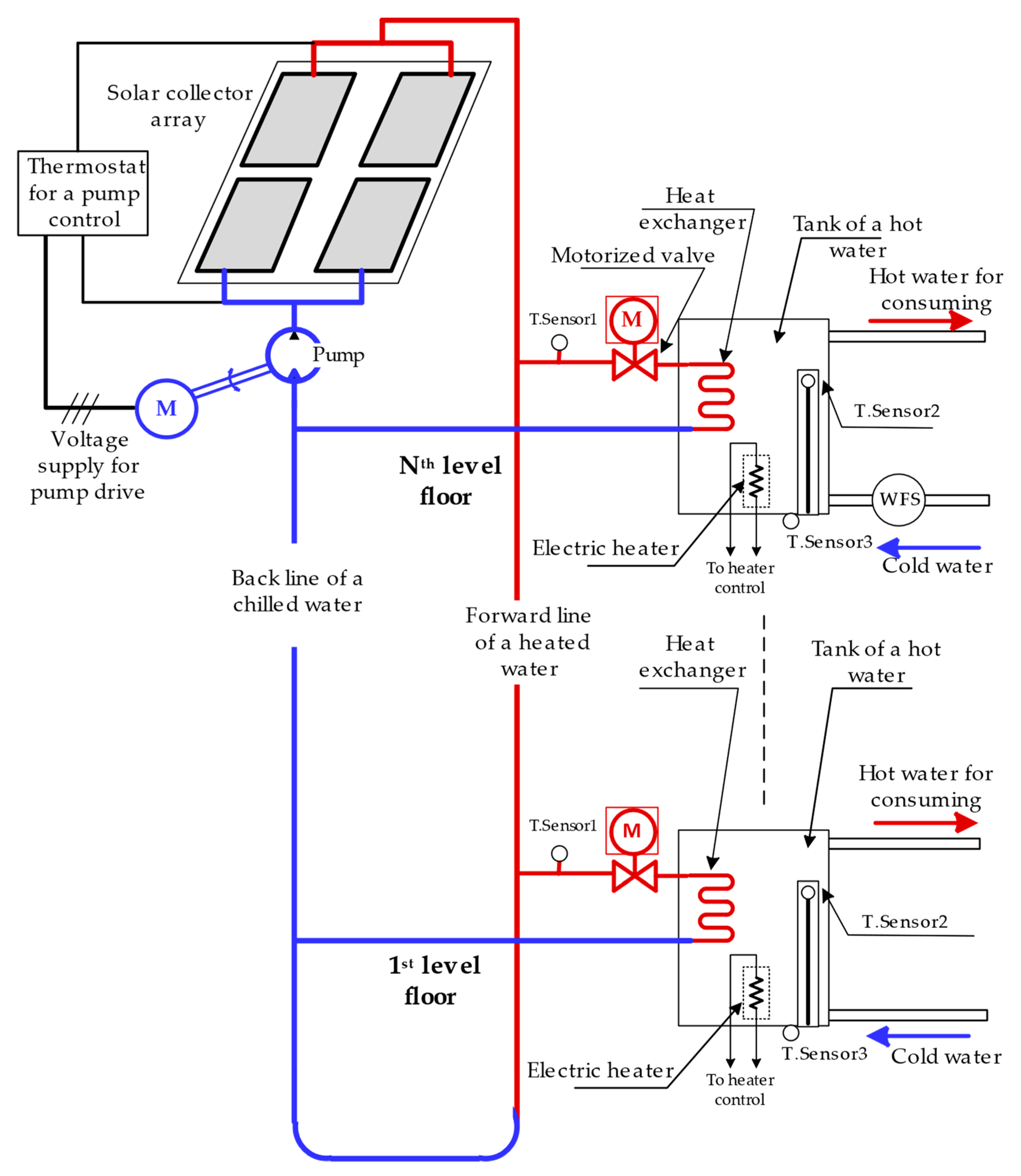
2.1. The Design and Functionality of a Conventional Water Heating System

The multi-story apartment building’s conventional water heating system, depicted in Figure 1, consists of a solar collector array designed to absorb heat energy. This array comprises multiple hydraulically connected solar units and is strategically mounted on the roof at an optimal angle relative to ground level (approximately 40°) and facing south. A hydraulic pump is integrated into the system to facilitate the forced hot coolant water stream, directing it from a backline to the forward pipe. The pump’s output is linked to the forward line of heated coolant, while its input is connected to the outlet of a backline supplying chilled water flow. This setup enables the pump to circulate coolant through the array of solar collectors, heating water before it is channeled into the forward pipe. From there, the pipe extends downwards from the solar array on the roof to the lowest ground story of the building. Each story of the building houses individual heating appliances located near the apartments. These appliances consist of a hot water storage tank and input/output connections for integration with the forward and backlines of the system, as well as connections to the home’s hot water supply. Inside, each water tank includes a heat exchanger and a supplementary electrical heater and a thermostat for preventing overheating and damage to the tank when electrical heating will be applied for a prolonged time and non-carefully. The thermostat operates as a circuit breaker, utilizing a bimetal strip that bends in response to excessive temperature increases. This bending action disconnects the terminals of the heater’s electrical contacts, effectively preventing further heating and damage.
The system also includes a control unit comprising a thermostat which reacts to the difference between input and output coolant temperature. When solar irradiation is sufficient for the coolant heating (temperature difference should be non-less than 3–4 °C) and its input temperature achieves a minimal level (~25 °C), the control unit switches on the pump motor for providing hot water circulation from the top to the lowest floor. This function is essential for the optimal use of solar irradiation.
In each story, the individual heating appliances receive hot coolant from a forward line, which then passes through a heat exchanger in the tank before circulating back through the back line. It is important to note that the flow of hot coolant is facilitated by a pressure drop between the forward and back lines, activated by the pump. As the hot coolant travels through the heat exchanger, it transfers some of its energy to the tank water, causing the temperature to rise. Consequently, as the coolant progresses from the input to the output, it loses energy and cools down slightly.
To guarantee a consistent hot water supply, two hydraulic connectors are fitted onto the tank. Positioned at the bottom, one connector serves as the entry point for cold water, while the other, situated on the upper side of the tank, is designated for hot water. The bottom connector is linked to the cold water tube from the apartment’s water system, while the upper connector is connected to the hot water tube in the home.
The operational mechanism of the system unfolds as follows: throughout daytime hours, spanning from morning until evening, hot coolant flows within a forward pipe, furnishing heated water to individual consumers across each floor of the building. It is pertinent to note that as the coolant traverses through individual heat exchangers, its temperature gradually diminishes. Consequently, residences situated on lower floors receive less thermal energy and experience slower heating, resulting in a reduction of water temperature. Consequently, it is advisable to refrain from installing such solar systems in buildings exceeding 10–11 stories.
A concise examination of the conventional solar heating system reveals notable drawbacks that warrant rectification. Firstly, there is a discernible discrepancy in water heating rates between upper and lower floors. Secondly, the necessity to ascertain a minimal coolant temperature threshold (~25 °C) and maintain its circulation continuously until solar irradiation achieves a specific increment (~3–4 °C) poses significant challenges. Meteorological data indicate a rising trend in coolant temperature within solar heating facilities, peaking around midday (~12–13 o‘clock) before gradually declining, albeit remaining above the designated minimal threshold of (~25 °C) set by the control unit. Consequently, water temperature in upper floors peaks around midday and subsequently declines, mirroring a similar trend albeit with a delay in lower floors, contingent upon the extent of hot water utilization within respective residences.
Furthermore, an undesirable scenario unfolds in instances where electrical heating is employed during daytime operations when coolant circulation persists. In such cases, a substantial proportion of electricity is squandered, as the coolant circulating through the heat exchanger has the potential to lower water temperature.
These identified drawbacks culminate in the wastage of both thermal and electrical energy, necessitating their mitigation. The proposed solution outlined in this study advocates for the implementation of dispersed individual control systems within each household’s water heating appliance. The core principles underpinning this solution are expounded upon in the subsequent section.

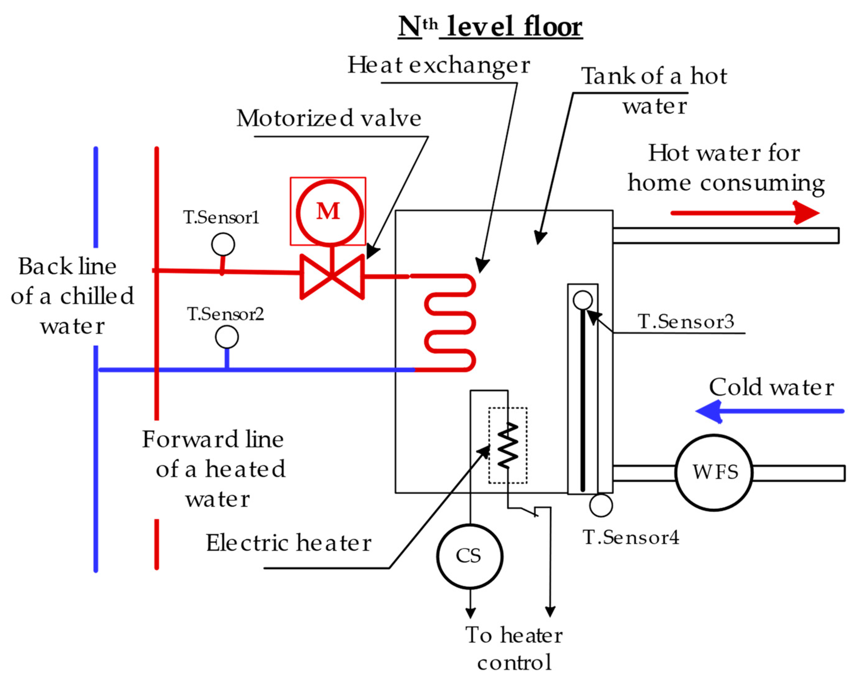
2.2. The Improved Individual Solar Heating Appliances

The individual solar heating appliance that is proposed in this work is depicted in Figure 2.
The proposed water heating appliance is founded upon a traditional storage tank with several modern enhancements. The primary innovation lies in the incorporation of a controllable motorized valve situated at the junction between the forward line and the inlet for a heat exchanger. The central concept of the upgrade revolves around regulating the flow of hot coolant passing through the heat exchanger within the tank. The flow of hot water is permitted only when the temperature of the coolant exceeds that of the water in storage. This seemingly straightforward innovation yields significant improvements in thermal and electrical energy efficiency for individual consumers and the entire building. However, implementing the algorithm necessitates access to coolant temperatures in both the forward line and the tank. To achieve this, three temperature sensors are strategically positioned. One is affixed to the forward pipe, carefully insulated to ensure precise measurements. Given the proliferation of solar system providers in the market, a pragmatic approach is required for tank temperature measurements. Inability to mandate sensor integration in every storage tank prompts the need for indirect temperature estimation. Consequently, two additional sensors are positioned: one near the upper region of the thermostat and another in proximity to the orifice of the thermostat tube. This solution draws inspiration from the thermal equivalent circuit for the steady-state thermodynamic mode depicted in Figure 3a,b.
The estimation of a water temperature inside a storage tank (TW) based on the equivalent thermal circuits carried out by Expression (1):
T W = T 3 1 + R 1 R 2 T 4 R 1 R 2
Thus, the water temperature can be expressed as a linear combination of two temperatures: one at the end and the other at the entrance of a thermostat tube. Following the implementation of a prototype model, the coefficients will be refined by fitting Expression (1) to measurement data, yielding their final values.
To validate the development concept, a prototype model was devised, encompassing an additional sensor (WFS in Figure 2) to monitor cold water flow rates from the home to the tank. This sensor essentially records domestic hot water usage. Additionally, to gauge electrical power consumption, a current sensor (CS in Figure 2) was integrated into the prototype. The primary objective of the prototype model is to assess the efficiency of the proposed approach and gather data for further system enhancements. Accordingly, the control system prototype was designed to collect all measurement data and upload it to a dedicated web page on the Internet.

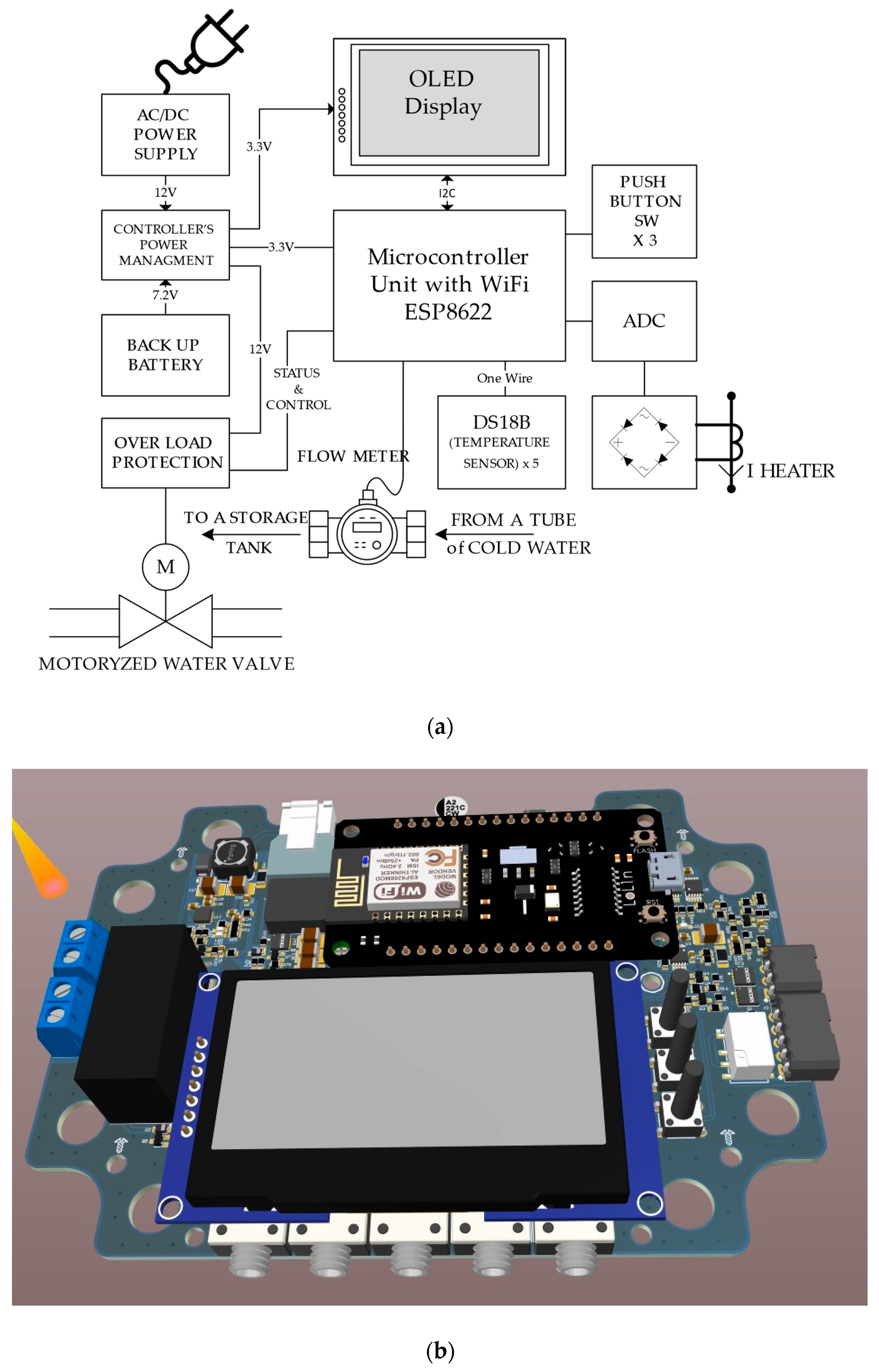
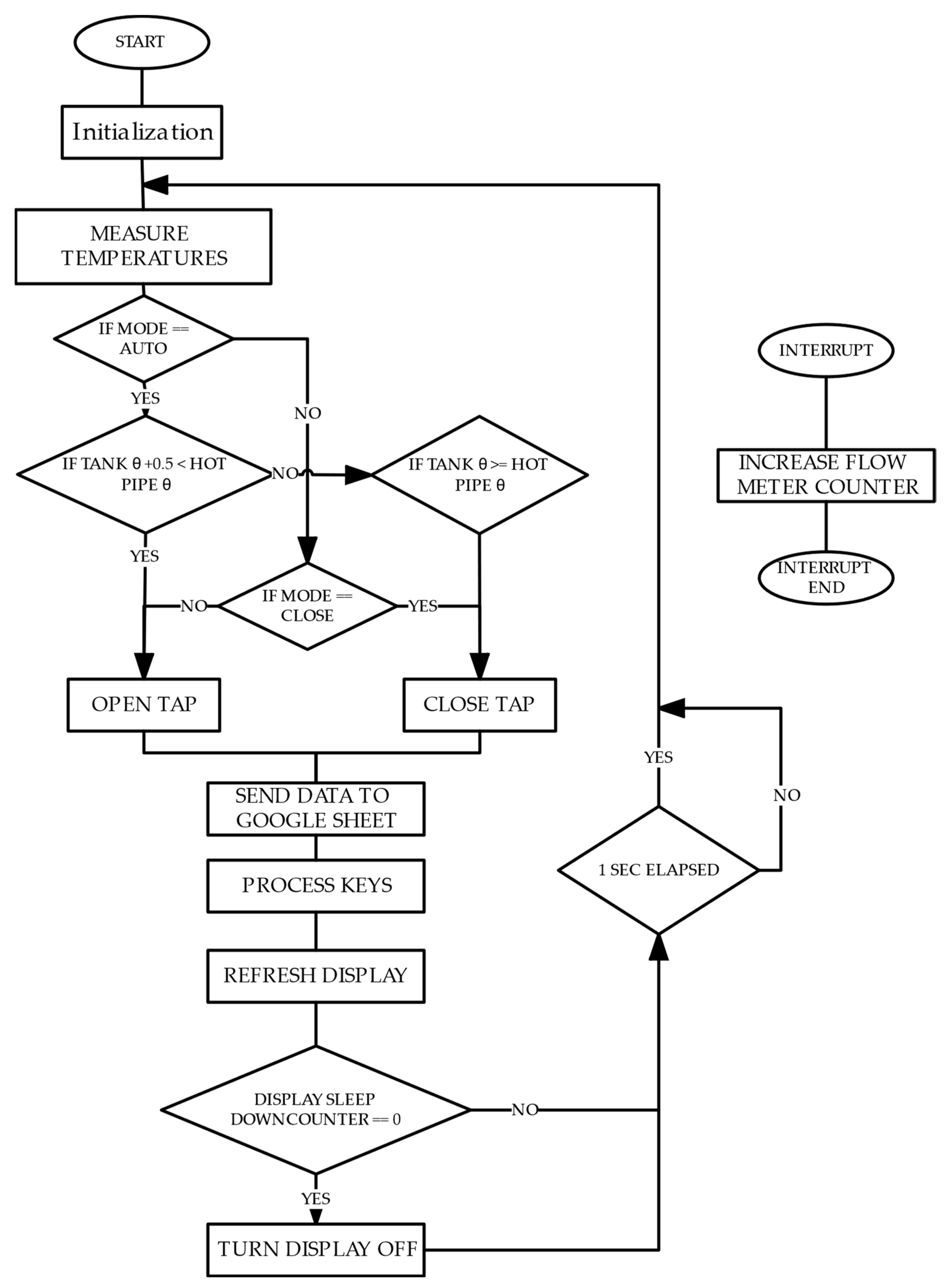
2.3. Control System Algorithm and Electronic Implementation

The experimental electronic system designed to validate the proposed control approach was developed and implemented within a designated residential unit. Tailored for individual household use, this control system comprises several components: a control unit (depicted in Figure 4a), a motorized valve integrated into the hot water pipeline (illustrated in Figure 4b) connecting to a heat exchanger, and multiple temperature sensors. Among these sensors, one is positioned along the hot water pipeline, while two reside within the storage tank. One sensor is situated within the thermostat housing, with the other placed nearby. An additional fourth temperature sensor is installed on the outlet pipe post-heat exchanger, whereas the fifth sensor is posed for the measurement of environmental temperature. The accuracy of the used sensors was ±0.5 °C.
To enhance functionality assessment, a flow meter for cold–hot water consumption was created. Notably, all these components interface with the control unit, tasked with hot water temperature monitoring, decision making regarding valve operation (on-off), and data collection and transmission to an Internet-based platform.
The control unit is additionally outfitted with an LCD monitor, providing a visual display of the temperatures involved in the system’s operation. The first line of the display indicates the temperature of the hot water in the forward hot pipe, while the second and third lines respectively depict the estimated temperatures of the hot water within the tank and its surrounding environment.
The display’s bottom line indicates the status of the water valve, signaling whether it is open or closed. It is worth noting that the control unit offers both manual and automatic operation modes. In automatic mode, the water valve is controlled based on the decision algorithm. However, users can also manually intervene, deciding to open or close the valve based on their assessment of the situation. Accordingly, the monitor displays the operational mode of the unit as “OPEN”, “CLOSE”, or “AUTO”.
The block schemes of the electronic board of the control unit and its electronic embodiment are represented in Figure 5.
The electronic board of the control unit includes the most important components such as motorized controllable water valve CWX-15N [29], five temperature sensors DS18B [30], water flow sensor YF-S201 [31], Node MCU module ESP8622 [32], and current sensor SCT013-010 [33]. Important aspects of the control unit are further described below.
Control design description: The controller features a meticulously designed PCB (Printed Circuit Board) tailored to meet the specific requirements of this project. Serving as the foundation for the controller’s functionality, the PCB integrates essential components to facilitate seamless operation. At the core of the PCB lies the Node MCU module, housing an ESP8622 microcontroller and offering built-in Wi-Fi connectivity for efficient data processing and communication.
Power management: The control unit employs an MP2615GQ-Z 2-cells charger [34] in conjunction with a PA-LNB76-C17UL.4.1. R001 battery [35], equipped with built-in protection mechanisms. This setup ensures continuous charging of the backup battery whenever grid power is accessible, enhancing system reliability and safety. Additionally, a voltage step-up mechanism stabilizes the 12 V bus voltage from the battery voltage, accommodating fluctuations ranging from 4.8 V to 8.2 V to ensure consistent power delivery. Furthermore, a power source selection mechanism seamlessly switches between the AC/DC power source and the battery during outages, ensuring an uninterrupted power supply to the system.
Overload protection of a motorized valve: The controller incorporates a current monitoring system utilizing INA381 [36], which detects overcurrent conditions and ensures system safety. The INA381 features an overcurrent output designed to trip if predetermined limits are exceeded. In such instances, the system automatically disables the power supply to the motorized valve, effectively mitigating potential hazards. Additionally, the MCU intervenes if the alert state is asserted, assessing real-time monitoring data to determine whether to enable further operation. This intervention enhances system safety and reliability by providing proactive protection against electrical faults.
OLED display [37]: Featuring a white color display with 128 × 64 pixels, the control unit provides real-time information to the user and allows for system configuration, including switching between automatic mode and manual control. This display serves as a user-friendly interface, enabling seamless interaction and adjustment of system settings for enhanced usability and convenience.
Provisions: The controller is outfitted with a provision for a two-pole relay capable of managing loads up to 250 V at 12 A. This provision enables adaptable control over external devices or systems, making it well suited for regulating the electrical heater of the boiler. Additionally, the controller features flash memory functionality, enabling data collection and storage in situations where internet connectivity is unavailable, ensuring continuity of data logging and system operation.
The control unit operates in accordance with the decisive algorithm of the water heating management, and it is represented in Figure 6.
The algorithm’s main loop operates on a continuous monitoring approach, sampling temperature readings at 60 s intervals. These readings serve as the basis for the controller’s decision-making process. Specifically, the algorithm compares the coolant temperature in the solar heating circuit with the boiler’s tank water temperature, triggering the opening of the motorized valve if the coolant temperature exceeds the tank temperature by at least 0.5 degrees. Conversely, if heat exchange conditions are unfavorable, the valve remains closed to prevent energy loss. A 0.5 degree hysteresis is incorporated to prevent oscillations and safeguard the system against potential damage. Furthermore, the user interface is managed by monitoring input from the user through three keys, each associated with specific functions displayed on the OLED display. These functions include an “AUTO” mode option for autonomous heat exchanger control, and manual control options to set the exchanger to “CLOSE” or “OPEN” states, irrespective of system temperatures. The OLED display conserves power by turning off and lighting up only upon key press, with a timeout feature activated after one minute of inactivity to minimize disturbance. In parallel, the algorithm incorporates a data logging feature to collect five temperatures, hot water consumption, and heating current readings and timestamps, transmitting them to a Google Sheet for further analysis. Leveraging the Google Sheets API enables seamless integration with the designated spreadsheet, facilitating real-time data transmission and archival.
The experimental model of the individual control unit was installed in an apartment on the 17th floor of a multi-story building with 19 floors. Two adults live in this home. Over a trial period of approximately six months, significant efficiency of the developed approach and the designed control unit was observed. The results of this usage are detailed in the following section of the article.

3. Results

The developed solar water heating system was installed in a 19-story building complex in Beer-Sheva, Israel. The building is located at a latitude of 31.25181 and a longitude of 34.7913. This area has a subtropical steppe desert climate with an average annual temperature of 19.5 °C (67.1 °F). The average cumulative annual solar irradiation is 6722 MJ/m2, and the average daily solar irradiation is 18.43 MJ/m2.
This section summarizes statistical data of the temperature change and usage of hot water as well as the surrounding measurements, which were obtained from the meteorological station located ~3 km from a building [32]. The data of a system operation were collected from a special Internet web page and is shown in Figure 7.
In the first column, the date of the measurements is displayed, while the second column indicates the exact time. The third to eighth columns present temperatures: ambient temperature outside the tank, temperature of the hot pipe, temperature in the output of the hot pipe after the heat exchanger, estimated temperature of hot water in the tank, and temperatures of the upper and lower sensors. The following column indicates the status of the valve (“CLOSE” or “OPEN”). The tenth column shows the minute usage of hot water (cm3), and the eleventh column indicates the mode of activation of the control unit (“Auto” or “Manual”). The final twelfth column represents the current of the electrical heater (mA).
During the initial stage, we conducted an analysis of the system’s overall functionality and observed temperature variations throughout the day, comparing them with meteorological data.

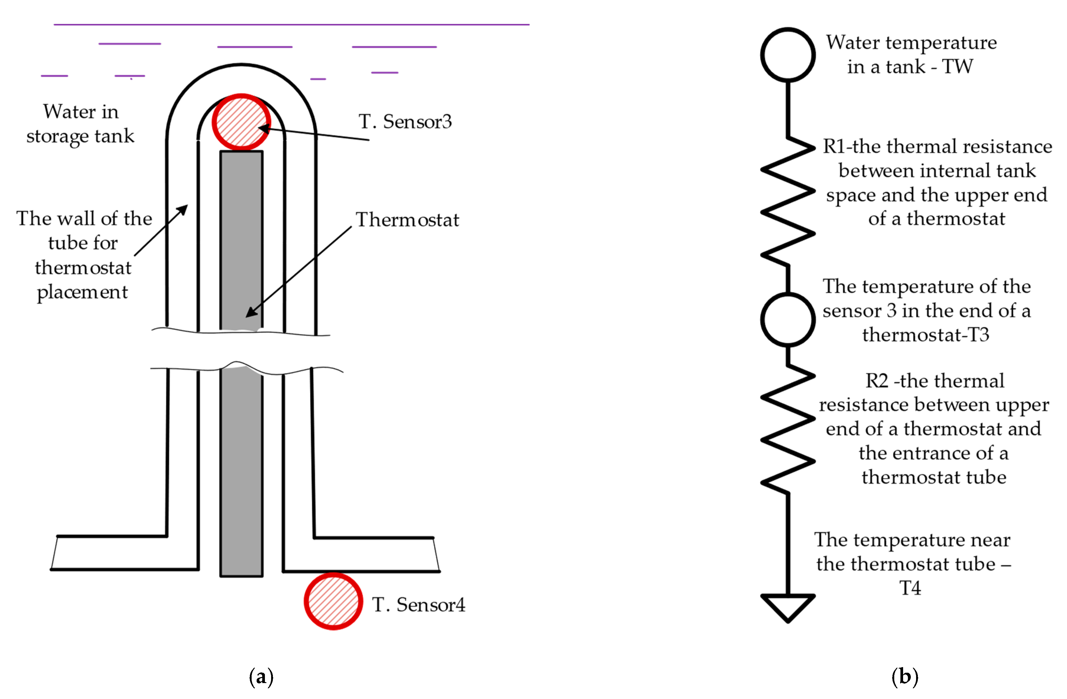
3.1. The Exactness of a Tank Hot Water Temperature Estimation

The importance of accurately estimating the tank water temperature is paramount as it directly affects the efficiency of heat absorption from solar collectors. If the estimated temperature exceeds the actual temperature, the valve will close prematurely, resulting in the tank water not receiving the maximum heat energy. Conversely, if the estimated temperature is lower than the actual temperature, the valve will remain open longer than necessary, resulting in the loss of some energy.
A specialized procedure is implemented, incorporating data from two sensors for temperature estimation. This procedure involves establishing a linear relationship between the actual temperature and the outputs of these sensors. The sensors are positioned as previously mentioned: one at the top of a thermostat inside the tank and the other near the orifice of the thermostat tube outside the tank. To assess the accuracy of this estimation method, samples of tank water were periodically collected and compared with the signals from the sensors. The findings of this analysis are depicted in Figure 8, where measured points are plotted alongside the 3-D linear approximation.
The function is approximating hot water temperature with those of sensors is as follows:
T W = 6.026 + 0.2336 · T U p p e r + 0.943 · T L o w e r
The coefficient of determination for the fitting closeness is R2 = 0.769, indicating a strong correlation between the approximating function and the real measurements. Additionally, the standard deviation between the approximating function and the real measurements is 1.8 °C.
Considering the proximity of the upper sensor to the tank wall, the feasibility of utilizing only this sensor for temperature estimation was explored. Figure 9 illustrates the tank temperature estimation solely based on the upper sensor.
The function is approximating hot water temperature with upper sensor is
T W = 19.01 + 0.591 · T U p p e r
The coefficient of determination for the fitting closeness is R2 = 0.64, indicating a weaker correlation compared to the previous approximation. Furthermore, the standard deviation of real measurements, represented by the mathematical expression, is much higher at 2.2 °C, which is approximately 22% worse. In accordance with what was demonstrated above, Function (2) was considered for the hot water temperature estimation.

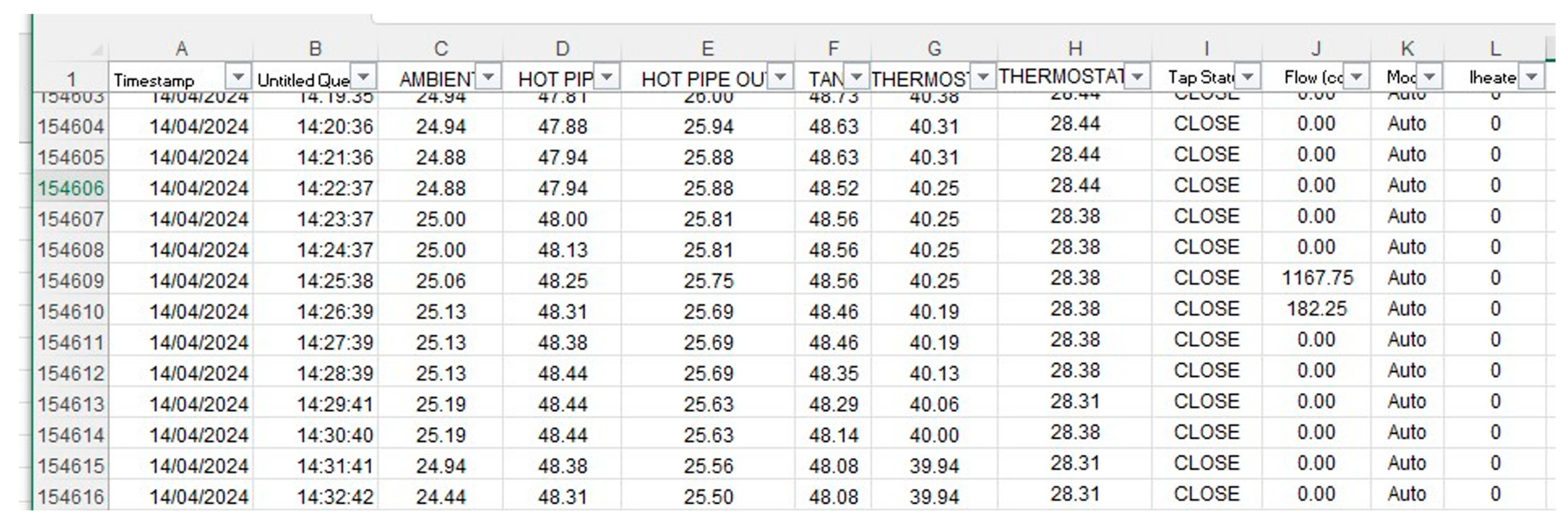
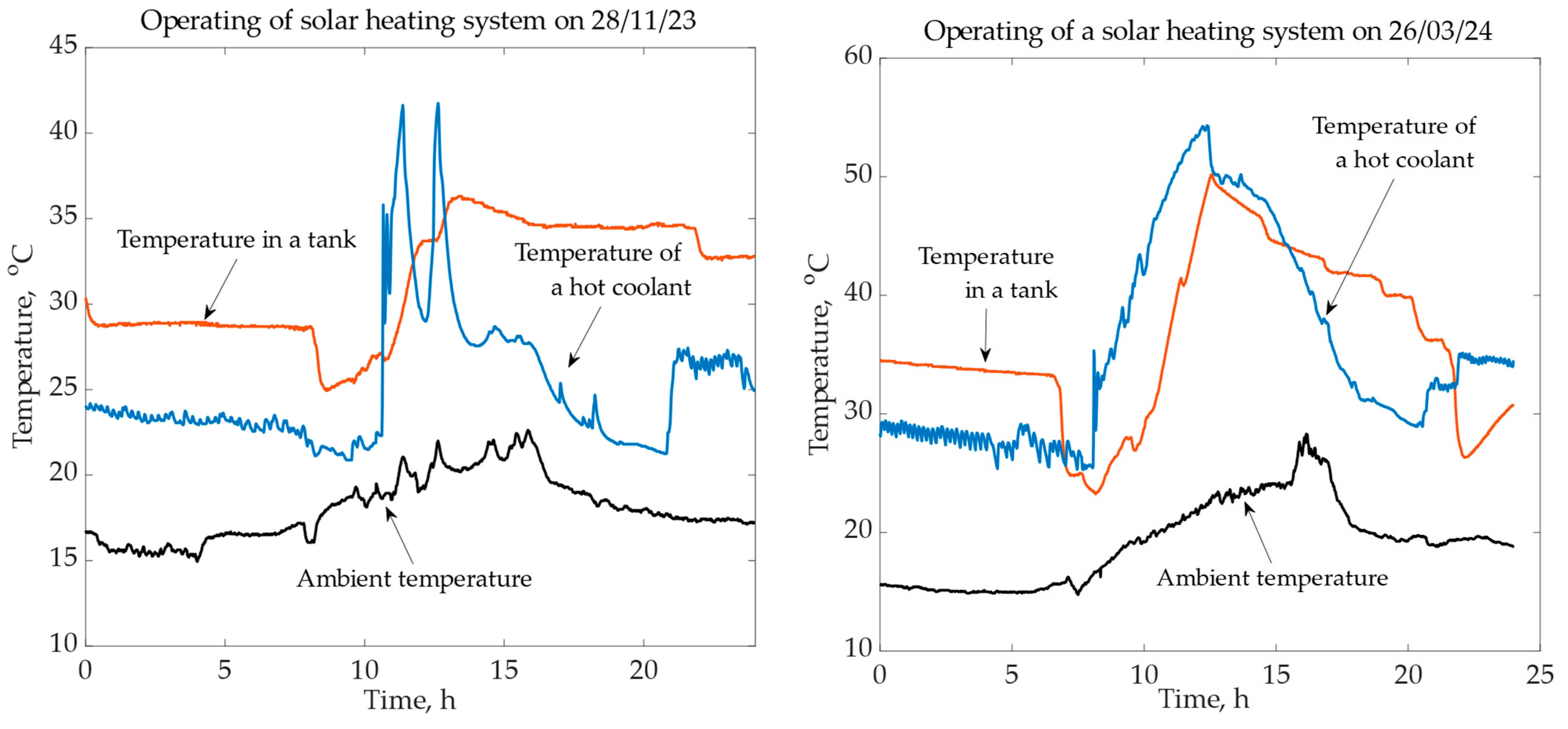
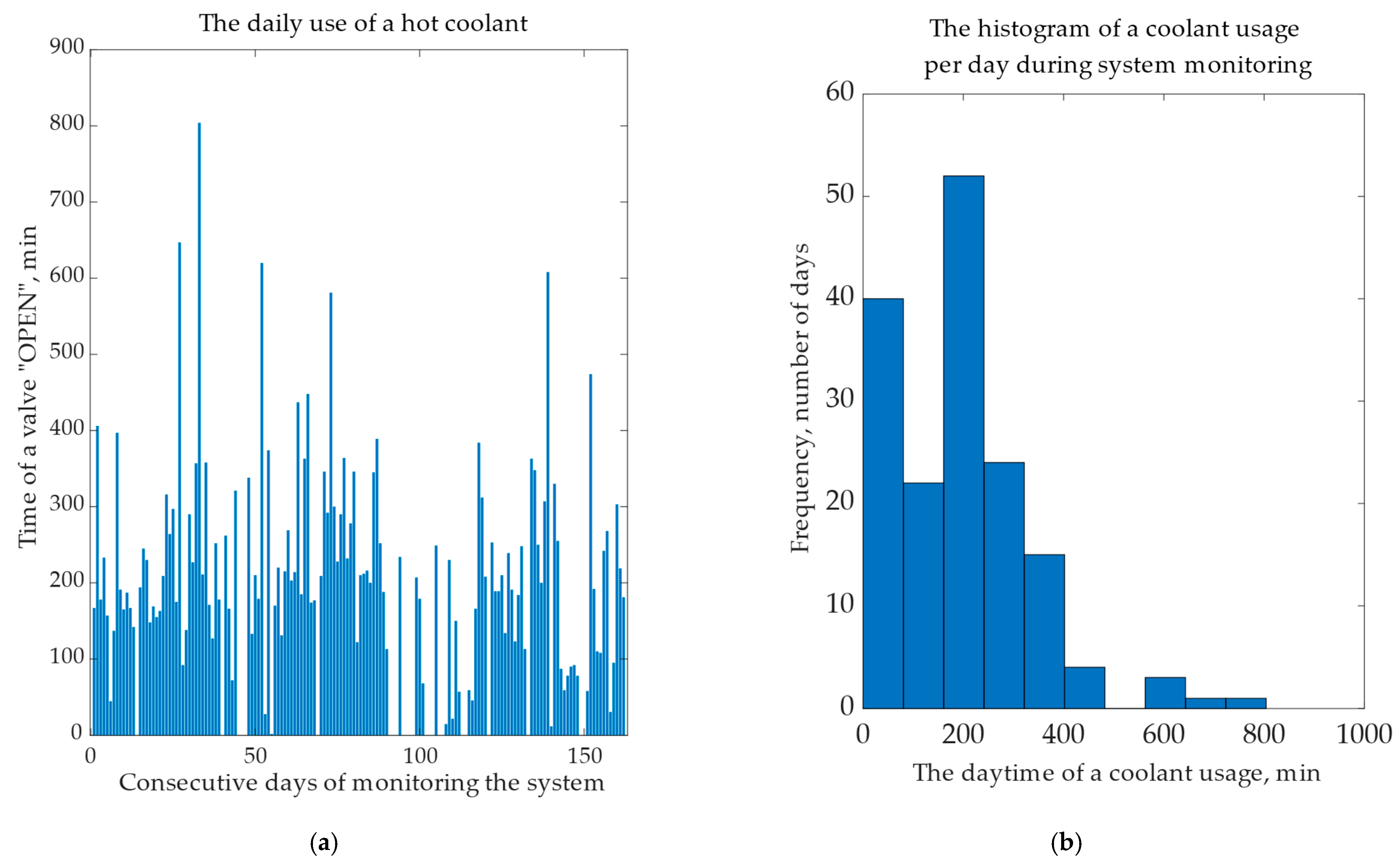
3.2. Statistic Data of the Solar Heating Operation with a Control Unit

First, a typical graph of temperature changes during the daytime is represented in Figure 10.
We observe a non-monotonic change in hot coolant temperature during late autumn and winter, while the spring and summer periods exhibit a more consistent deviation in coolant temperature.
Significant findings have emerged regarding hot water usage and energy consumption for the electrical heater. These findings allow us to draw conclusions about the energy efficiency of the developed approach. Graphs (Figure 11) illustrating the cumulative time when a valve is open, allowing the flow of hot coolant through a heat exchanger in individual storage tanks, are presented below.
The average duration that the motorized valve remains open during the average day is 189.6 min, with a standard deviation (STD) of 143.8 min. The relation between STD and average value is ~0.76 (76%), indicating significant variability in the usage of hot water.
No less important is the total and daily usage of hot water since it will allow us to estimate the potential saving of electricity (Figure 12a,b).
Average use of daily hot water is Vav = 59.4 L/day, STD—38.3 L. The relation of S T D A V E R A G E = 0.64   ( 64 % ) .
The graphs in Figure 13 represent the consumption of electricity for water heating alongside solar energy utilization, particularly during periods of insufficient solar irradiation.
The average electricity consumption is equal to Wav = 0.116 kWh with STD—0.35 kWh that is much bigger than the average value.
Summarizing the hot water usage and electricity consumption, we can conclude that the solar water heating system effectively reduces electricity consumption, bridging the gap designated as W E :
W E = V a v · 1000 · θ a v · 4.184 3.6 · 10 6 · η T W a v
where Average daily water consumption Vav, the average gap between input and output water temperatures θ a v 45.8   ° C 14.5   ° C = 27.3   ° C , and the total efficiency of electrical heater η T is equal to ~88–90% maximum.
The average electricity savings following the adjustment of parameter magnitudes are calculated at 2.005 kWh/day. While this may not seem substantial due to the modest hot water usage observed, households with larger numbers of occupants and consequently higher hot water consumption could realize considerably greater electricity savings, potentially reaching 3–5 kWh/day. Permanent system monitoring is essential for a more precise estimation of energy and economic benefits and, therefore, should be continued.

4. Discussion and Conclusions

The analysis conducted in this study of a solar heating system, which has been developed and in operation since November 2023, demonstrates the efficacy of individual solar heating appliances in multi-story buildings.. It underscores the significance of implementing individual solar control systems for each apartment, enabling the optimal utilization of solar thermal energy.
To verify this idea, a specific control device was created and installed in a home to control the hot coolant circulation in the storage tank. This system, which consists of a control unit, a motorized water valve, and many temperature sensors, manages how solar energy is used to heat water in individual residences. To ensure accurate control and monitoring of the system, the control unit includes sophisticated components such as an OLED display, a current sensor, and a customized MCU module.
To guarantee continuous functioning in the case of a power outage, the control unit is also outfitted with two power sources: an AC network and a Li-ion battery. It also serves as a data hub, gathering measurements in real time and sending them with a one-minute resolution to a specific Internet platform. This makes it easier to continuously monitor and analyze the operation of the system.
The analysis of system functionality reveals that tank water temperature estimation can be carried out even through indirect measurements. The error margins can be achieved inside ±1.2 °C, which is acceptable for operational purposes. The duration of hot coolant transfer from centralized solar collectors through the tank heat exchanger is relatively short, averaging approximately 190 min (with a standard deviation of around 144 min) during the daytime, slightly exceeding 3 h. Considering that the average suitable irradiation for solar energy collection around the building is approximately 7.5 h, it indicates that the efficiency of solar energy utilization remains relatively low.
The daily average usage of hot water in the studied apartment is approximately 60 L, reflecting the limited number of occupants (two adults only). Increasing the number of occupants in homes equipped with solar water heating systems would undoubtedly enhance their efficiency.
Solar water heating contributes to electricity savings, thus mitigating the environmental impact from conventional power generation fueled by fossil fuels. In this study, electricity savings amounted to approximately 2.0 kWh per day. Homes with higher population densities can expect even more significant electricity savings, averaging between 3 and 5 kWh per day.
This investigation holds significant importance in expanding the application of renewable energy sources. Solar heating for domestic water not only curtails pollution from conventional electric power stations but also offers cost-effective thermal energy for household applications.
Therefore, it is recommended to further pursue research for optimizing solar water heating development. Continuation of system monitoring and analysis of collected data is also advised for future investigations into solar energy systems.

Author Contributions

Conceptualization, M.A. and M.K.; methodology, M.A.; software, M.K.; validation, M.A. and M.K.; formal analysis, M.A.; investigation, M.K.; resources, M.A.; data curation, M.A.; writing—original draft preparation, M.A.; writing—review and editing, M.A.; visualization, M.K.; supervision, M.A. All authors have read and agreed to the published version of the manuscript.

Funding

This research received no external funding.

Data Availability Statement

The original contributions presented in the study are included in the article material; further inquiries can be directed to the corresponding author.

Conflicts of Interest

The authors declare no conflicts of interest.

References

  1. Thirugnanasambandam, M.; Iniyan, S.; Goic, R. A review of solar thermal technologies. Renew. Sustain. Energy Rev. 2010, 14, 312–322. [Google Scholar] [CrossRef]
  2. Ibrahim, O.; Fardoun, F.; Younes, R.; Louahlia-Gualous, H. Review of water-heating systems: General selection approach based on energy and environmental aspects. Build. Environ. 2014, 72, 259–286. [Google Scholar] [CrossRef]
  3. Streicher, W. Solar thermal technologies for domestic hot water preparation and space heating. In Renewable Heating and Cooling; Elsevier: Amsterdam, The Netherlands, 2016; pp. 9–39. [Google Scholar]
  4. Al-Mamun, M.R.; Roy, H.; Islam, M.S.; Ali, M.R.; Hossain, M.I.; Aly, M.A.S.; Khan, M.Z.H.; Marwani, H.M.; Islam, A.; Haque, E. State-of-the-art in solar water heating (SWH) systems for sustainable solar energy utilization: A comprehensive review. Sol. Energy 2023, 264, 111998. [Google Scholar] [CrossRef]
  5. Wang, Z.; Yang, W.; Qiu, F.; Zhang, X.; Zhao, X. Solar water heating: From theory, application, marketing and research. Renew. Sustain. Energy Rev. 2015, 41, 68–84. [Google Scholar] [CrossRef]
  6. Huang, D.; Ma, H.; Ma, S.; Chen, M.; Xu, C.; Zhang, Y.; Yan, C. Study on the Energy Efficiency Improvement and Operation Optimization of a Solar Water Heating System. Appl. Sci. 2022, 12, 7263. [Google Scholar] [CrossRef]
  7. Artur, C.; Neves, D.; Cuamba, B.C.; Leão, A.J. Domestic hot water technology transition for solar thermal systems: An assessment for the urban areas of Maputo city, Mozambique. J. Clean. Prod. 2020, 260, 121043. [Google Scholar] [CrossRef]
  8. Coelho, L.; Koukou, M.K.; Konstantaras, J.; Vrachopoulos, M.G.; Rebola, A.; Benou, A.; Karytsas, C.; Tourou, P.; Sourkounis, C.; Gaich, H. Assessing the Effectiveness of an Innovative Thermal Energy Storage System Installed in a Building in a Moderate Continental Climatic Zone. Energies 2024, 17, 763. [Google Scholar] [CrossRef]
  9. Martinopoulos, G.; Papakostas, K.T.; Papadopoulos, A.M. Comparative analysis of various heating systems for residential buildings in Mediterranean climate. Energy Build. 2016, 124, 79–87. [Google Scholar] [CrossRef]
  10. Umer, M.; Dilshad, S.; Akbar, A.; Abas, N. Simulation Analysis of Solar Thermal Water Heating System for Climate of Lahore. In Proceedings of the 2022 International Conference on Emerging Trends in Electrical, Control, and Telecommunication Engineering (ETECTE), Lahore, Pakistan, 2–4 December 2022; IEEE: Piscataway, NJ, USA, 2022; pp. 1–6. [Google Scholar]
  11. Hernandez Uribe, O.; San Martin, J.P.; Garcia-Alegre, M.C.; Santos, M.; Guinea, D. Smart building: Decision making architecture for thermal energy management. Sensors 2015, 15, 27543–27568. [Google Scholar] [CrossRef] [PubMed]
  12. Standard ISO 9459-5:2007. Available online: www.iso.org/standard/39820.html (accessed on 1 March 2024).
  13. Yoo, M. Optimal Design and Parameter Estimation for Small Solar Heating and Cooling Systems. Sustainability 2023, 15, 16352. [Google Scholar] [CrossRef]
  14. Lillo-Bravo, I.; Vera-Medina, J.; Fernandez-Peruchena, C.; Perez-Aparicio, E.; Lopez-Alvarez, J.A.; Delgado-Sanchez, J.M. Random Forest model to predict solar water heating system performance. Renew. Energy 2023, 216, 119086. [Google Scholar] [CrossRef]
  15. Azzouzi, M. Control of solar water heater design. In Proceedings of the 2011 10th International Conference on Environment and Electrical Engineering, Rome, Italy, 8–11 May 2011; IEEE: Piscataway, NJ, USA, 2011; pp. 1–5. [Google Scholar]
  16. Dbouk, H.M.; Ali, R.A.; Ghamlouch, M.; Elhajj, I.H. Temperature Control for Residential Solar Water Heating Systems. In Proceedings of the IEEE EUROCON 2019—18th International Conference on Smart Technologies, Novi Sad, Serbia, 1–4 July 2019; IEEE: Piscataway, NJ, USA, 2019; pp. 1–6. [Google Scholar]
  17. Cui, X.; Kou, Z.; Qiao, Y. Water-level Control System for Solar Water Heating Engineering based on PLC. In Proceedings of the 2019 IEEE 3rd Information Technology, Networking, Electronic and Automation Control Conference (ITNEC), Chengdu, China, 15–17 March 2019; IEEE: Piscataway, NJ, USA, 2019; pp. 1625–1628. [Google Scholar]
  18. Muñiz, R.; del Coso, R.; Nuño, F.; Villegas, P.J.; Álvarez, D.; Martínez, J.A. Solar-Powered Smart Buildings: Integrated Energy Management Solution for IoT-Enabled Sustainability. Electronics 2024, 13, 317. [Google Scholar] [CrossRef]
  19. Shi, F.; Kou, Z.; Li, W.; Chen, J. Design and Application of Water-temperature Measurement and Control System for Solar Water-heating Engineering Device. In Proceedings of the 2020 IEEE 4th Information Technology, Networking, Electronic and Automation Control Conference (ITNEC), Chongqing, China, 12–14 June 2020; IEEE: Piscataway, NJ, USA, 2020; pp. 1741–1745. [Google Scholar]
  20. Halam, R.; Raman, R. Enhancing Energy Efficiency in Solar Water Heating Systems for Sustainable Homes with IoT Technology. In Proceedings of the 2023 International Conference on Innovative Computing, Intelligent Communication and Smart Electrical Systems (ICSES), Chennai, India, 14–15 December 2023; IEEE: Piscataway, NJ, USA, 2023; pp. 1–6. [Google Scholar]
  21. Znaczko, P.; Kaminski, K.; Chamier-Gliszczynski, N.; Szczepanski, E.; Gołda, P. Experimental analysis of control methods in solar water heating systems. Energies 2021, 14, 8258. [Google Scholar] [CrossRef]
  22. Zhou, C.; Liang, R.B.; Zhang, J.L. Optimization design method and experimental validation of a Solar PVT cogeneration system based on building energy demand. Energies 2017, 10, 1281. [Google Scholar] [CrossRef]
  23. Li, W.; Thirugnanam, K.; Tushar, W.; Yuen, C.; Chew, K.T.; Tai, S. Improving the operation of solar water heating systems in green buildings via optimized control strategies. IEEE Trans. Ind. Inform. 2018, 14, 1646–1655. [Google Scholar] [CrossRef]
  24. Zhao, Z.; Wang, C.; Wang, B. Adaptive model predictive control of a heat pump-assisted solar water heating system. Energy Build. 2023, 300, 113682. [Google Scholar] [CrossRef]
  25. Liao, Z.; Dexter, A.L. An inferential model-based predictive control scheme for optimizing the operation of boilers in building space-heating systems. IEEE Trans. Control Syst. Technol. 2009, 18, 1092–1102. [Google Scholar] [CrossRef]
  26. Jamaaoui, F.; Puig, V.; Ayadi, M. Optimal Control of Hybrid Photovoltaic/Thermal Water System in Solar Panels Using the Linear Parameter Varying Approach. Processes 2023, 11, 3426. [Google Scholar] [CrossRef]
  27. Azzouzi, M.; Attia, B.; Hourier, B.; Messaoudi, M. Realization of solar water heating controlling board. In Proceedings of the 2011 International Conference on Multimedia Computing and Systems, Ouarzazate, Morocco, 7–9 April 2011; IEEE: Piscataway, NJ, USA, 2011; pp. 1–4. [Google Scholar]
  28. Salamone, F.; Belussi, L.; Danza, L.; Ghellere, M.; Meroni, I. An open-source low-cost wireless control system for a forced circulation solar plant. Sensors 2015, 15, 27990–28004. [Google Scholar] [CrossRef] [PubMed]
  29. Mini Motorized Valve. Available online: https://www.motorisevanne.com/product-category/mini-motorized-valve/cwx-15n/ (accessed on 12 April 2024).
  30. Temperature Sensors. Available online: https://www.digipart.com/part/DS18B20?msclkid=10cd41f7998717c1aae027b5e042b141&utm_source=bing&utm_medium=cpc&utm_campaign=Tier_Popar&utm_term=DS18B20&utm_content=Tier_Popular_0 (accessed on 12 April 2024).
  31. Water Flow Measurement Sensor YF-S201. Available online: https://components101.com/sensors/yf-s201-water-flow-measurement-sensor (accessed on 11 March 2024).
  32. Wi-Fi Module. Available online: https://microcontrollerslab.com/esp8266-getting-started-tutorial/ (accessed on 29 April 2024).
  33. Current Sensor. Available online: http://en.yhdc.com/comp/file/download.do?id=943 (accessed on 20 April 2024).
  34. Li-Ion Battery Charger. Available online: https://www.monolithicpower.com/en/mp2615.html (accessed on 20 April 2024).
  35. Two Cell Li-Ion Battery. Available online: https://www.feyelektronik.de/downloads/db-pa-iec-lnb76.pdf (accessed on 20 April 2024).
  36. Current Monitor. Available online: https://www.ti.com/product/INA381/part-details/INA381A1IDGSR (accessed on 20 April 2024).
  37. OLED Display 128x64. Available online: https://www.diymore.cc/products/2-42-inch-12864-oled-display-module-iic-i2c-spi-serial-for-arduino-c51-stm32-green-white-blue-yellow?_pos=6&_sid=f4f532b3b&_ss=r (accessed on 20 April 2024).
  38. MATLAB Colomap. Available online: https://www.mathworks.com/help/matlab/ref/colormap.html (accessed on 9 February 2024).
Figure 1. A conventional water heating system in the multi-story apartment building. The red color is used for pipes with hot whereas blue color for cold water pipes. The letter M is used for the motorized valve symbol.
Electronics 13 02305 g001
Figure 2. The individual water heating appliance in the multi-story apartment building. WFS—the water flow sensor providing the information of a water flow rate to the control system; CS—current sensor of the electrical heater. The red color is used for pipes with hot whereas blue color for cold water pipes. The letter M is used for the motorized valve symbol.
Electronics 13 02305 g002
Figure 3. The placement of temperature sensors inside and near the tube of a thermostat (a) and the equivalent circuit of a temperature measurements. (a) The placement of the upper and lower temperature sensors inside and near the thermostat tube. Purpil lines simbolize a water in storage tank. (b) The equivalent termal circuit for the assessment of a tank hot water temperature.
Electronics 13 02305 g003
Figure 4. The individual control unit (a) and motorized valve (b) installed in the line from hot water pipe and storage tank heat exchanger.
Electronics 13 02305 g004
Figure 5. The block scheme of the control unit (a) and its electronic embodiment (b).
Electronics 13 02305 g005
Figure 6. The algorithm for the individual solar water heating control unit.
Electronics 13 02305 g006
Figure 7. The internet page of the information regarding measured parameters.
Electronics 13 02305 g007
Figure 8. The 3-D plot of temperature measurements. Designated following temperatures: TW—hot water in a storage tank, TLower, TUpper—outputs of sensors in the bottom and on a top of a thermostat. Colors in Figure 8 depict the colormap Parula acceptable in MATLAB software [38].
Electronics 13 02305 g008
Figure 9. The 2-D plot illustrates temperature measurements, specifically representing the hot water temperature using only the upper sensor.
Electronics 13 02305 g009
Figure 10. Typical graphs of temperature in a tank, of a hot coolant and ambient for late autumn and spring.
Electronics 13 02305 g010
Figure 11. Data on the usage of hot coolant during days of system monitoring: (a) in consecutive days; (b) histogram of time valve “ON “distribution.
Electronics 13 02305 g011
Figure 12. Data of daily usage of hot water; (a) graph in consecutive days; (b) histogram of water volume use.
Electronics 13 02305 g012
Figure 13. Data of electricity daily usage.
Electronics 13 02305 g013
Disclaimer/Publisher’s Note: The statements, opinions and data contained in all publications are solely those of the individual author(s) and contributor(s) and not of MDPI and/or the editor(s). MDPI and/or the editor(s) disclaim responsibility for any injury to people or property resulting from any ideas, methods, instructions or products referred to in the content.

