Article

Anti-Resonant Hollow-Core Fibers with High Birefringence and Low Loss for Terahertz Propagation

1
Bell Honors School, Nanjing University of Posts and Telecommunications, Nanjing 210023, China
2
College of Electronic and Optical Engineering, Nanjing University of Posts and Telecommunications, Nanjing 210023, China
*
Author to whom correspondence should be addressed.
Electronics 2024, 13(12), 2382; https://doi.org/10.3390/electronics13122382
Submission received: 28 May 2024 / Revised: 13 June 2024 / Accepted: 17 June 2024 / Published: 18 June 2024

Abstract

:
A new type of anti-resonant hollow-core fiber for terahertz waveguides is proposed. By introducing central support pillars and an elliptical structure, the fiber achieves high birefringence while maintaining low confinement loss and low material absorption loss. The fiber structure is optimized through simulation using the finite element method. The optimized fiber exhibits a birefringence of up to 1.22 × 10⁻² at a frequency of 1 THz, with a confinement loss of 8.34 × 10⁻⁶ dB/cm and a material absorption loss of 7.17 × 10⁻³ dB/cm. Furthermore, when the bending radius of the fiber is greater than 12 cm, the bending loss of the anti-resonant optical fiber at 1 THz is less than 1.36 × 10⁻⁴ dB/cm, demonstrating good bending resistance and high practical value. It is expected to play a significant role in optical communication systems.

1. Introduction

The terahertz waveband, situated between the microwave and infrared wavebands, has a frequency range of 0.1 to 10 THz and corresponding wavelengths ranging from 30 to 3000 µm. Compared to other wavebands, terahertz waves possess characteristics such as penetrability [1] and safety [2], along with abundant light sources [3] and high-resolution capabilities [4]. Over the past few decades, terahertz waves have found wide-ranging applications in fields such as security detection [5], medical imaging [6], material identification [7], wireless communication [8], data transmission [9], and sensing [10]. However, the transmission of terahertz waves is susceptible to environmental influences due to their high absorption by water vapor and certain materials, leading to significant transmission losses that hinder their development. To address this challenge, researchers have developed various low-loss waveguides for the terahertz waveband, including metal wires [11], parallel plates [12], subwavelength fibers [13], dielectric slab waveguides [14], porous-core fibers [15], and hollow-core fibers [16]. Among these, hollow-core fibers (HCFs) have attracted significant attention in recent years in the field of terahertz waveguides. HCFs are characterized by dry air within their cores, resulting in minimal absorption of terahertz waves during transmission. They also exhibit features such as low latency [17], low dispersion [18], and low nonlinearity [19], enabling low-loss [20], high-power, and high-speed transmission, showcasing their strong application potential.
According to the principle of light guidance, HCFs can be mainly divided into two categories [21]. The first type are known as photonic bandgap fibers (PBGFs), which utilize the photonic bandgap effect to guide light within the fiber core and limit the modes in the core region. Since the first photonic bandgap hollow-core fiber (PBG-HCF) was manufactured in 1999 [22], various structures of such fibers have been reported. In 2004, Chen et al. fabricated a PBG-HCF with high birefringence, achieving a birefringence of 2.5 × 10⁻² and a loss of 1.5 × 10⁻² dB/cm in the wavelength range of 1.55~1.625 µm [23]. In 2014, Fini et al. investigated a 19-cell PBG-HCF, achieving a minimum loss of 4.9 ± 0.6 dB/m in the wavelength range of 1.526~1.54 µm [24]. However, researchers have discovered that the loss in PBG-HCFs is mainly due to surface scattering losses, which cannot be fundamentally eliminated, making it challenging to further reduce the loss [25]. Additionally, PBG-HCFs suffer from drawbacks such as a narrow bandwidth and poor mode purity.
The second type of HCF is the anti-resonant hollow-core fiber (AR-HCF), which combines anti-resonant reflection and suppressed coupling effects for guidance [26]. Anti-resonance typically refers to a mechanism that utilizes the interference of light waves between the cladding and the core of an optical fiber to reduce or prevent light from leaking out of the fiber [27]. AR-HCFs are believed to offer a lower loss, a higher transmission bandwidth, and increased birefringence compared to PBG-HCFs. Ding et al. discovered a transmission belt with hybrid resonance characteristics in AR-HCFs [28], resulting in a birefringence of 10−4. Mousavi et al. systematically investigated various methods to introduce high birefringence into AR-HCFs [29], achieving a birefringence of 1.5 × 10⁻⁴ and a total loss of 7.6 × 10⁻⁴ dB/cm at 1.55 µm by optimizing the nodeless fiber structure. Hong et al. fabricated an AR-HCF with a birefringence of 9.1 × 10⁻⁵, achieving a minimum loss of 185 dB/km at 1.589 µm [30]. Xue et al. utilized 3D printing technology to fabricate a high birefringence of 10−2 but with a total loss of 0.96 dB/cm at 0.27 THz [31]. The current focus is on finding ways to achieve higher birefringence with lower loss.
This paper presents an AR-HCF with high birefringence and low loss characteristics. Compared to previous studies, which mostly involved changing the cladding of the optical fiber [32], this AR-HCF introduces central support pillars and an elliptical structure into the core of the fiber, greatly increasing the asymmetry of the structure, resulting in a birefringence of 10−2 with a confinement loss (CL) of only 10−6 dB/cm and a material absorption loss (MAL) of only 10−3 dB/cm. Compared to existing structures, it can achieve higher birefringence with lower losses. Additionally, this AR-HCF also exhibits excellent bending resistance, with a bending loss of only 10−4 dB/cm when the bending radius exceeds 12 cm at 1 THz. This structure not only achieves excellent optical properties but also provides new ideas and solutions for the development of AR-HCFs towards lower losses and higher birefringence.

2. Structure and Principle

Figure 1 illustrates the cross-sectional structure of the proposed AR-HCF. The outer cladding of the AR-HCF consists of four semi-circular components, each nested with a circular cladding. Compared to a fully circular cladding, the use of semi-circular cladding provides better transmission characteristics and greater structural flexibility, while also reducing the manufacturing complexity [20,33]. The radius of the semi-circular cladding is denoted as R, and the radius of the nested circular cladding is denoted as Rn, with both having a thickness of g. The central part of the fiber is composed of two supports and an elliptical structure. Two supports will pass through the interior of the elliptical tube, as shown in the magnified part of Figure 1. It is this introduced structure that disrupts the symmetry of the fiber, resulting in higher birefringence and reduced losses. The thickness of the two long tubes and the elliptical tube is denoted as t. The major axis of the ellipse is denoted as da, and the ratio of the minor axis length to the major axis length is denoted as e. Finite element method simulations were conducted on this fiber structure. The outermost layer of the fiber was set as a perfect matching layer, with a grid size of λ/6 in the core section and λ/4 elsewhere. The entire AR-HCF is made of the non-polarized cyclo-olefin copolymer TOPAS. In the 0.1~2 THz range, TOPAS exhibits a highly constant refractive index of 1.5258 [34], indicating low material dispersion in this THz band. Furthermore, TOPAS has excellent low water absorption and high transparency, making it widely used in the manufacture of THz fibers [35].
Based on the principle of the AR-HCF, coupling between the core mode and cladding modes is more likely to occur at the resonant frequency, resulting in higher transmission losses. Therefore, in the fiber design, it is recommended to minimize the occurrence of resonant frequencies to reduce the losses. The resonant frequency can be expressed as [34]:
f c = m c 2 g n 2 1 ,
where m is the resonance order, c is the speed of light in free space, n is the effective refractive index of TOPAS, and g represents the thickness of the cladding tube. Setting g = 70 µm, the corresponding resonant frequency is 1.86 THz as m = 1.
The two fundamental modes present in the AR-HCF, as shown in Figure 2, are x-polarized (x-pol) and y-polarized (y-pol) modes. The introduction of the central pillars and elliptical tube disrupts the symmetry of the fiber structure, leading to increased birefringence. Birefringence can be expressed as follows:
B = | n e f f x n e f f y | ,
B = | n e f f x n e f f y | , where n e f f x and n e f f y represent the effective refractive indices for the x-pol and y-pol modes, respectively.
For the AR-HCF, minimizing losses during transmission is crucial. CL, the primary loss incurred during light transmission, arises from the power losses caused by optical field leakage, determined by the fiber structure, which can be calculated using the following formula [36]:
C L = 8.686 × 2 π f c Im ( n e f f ) × 10 2 , d B / cm
where f is the operating frequency of the optical fiber, and Im(neff) refers to the imaginary part of the effective refractive index in the concept of the complex refractive index.
Another type of loss in the transmission of the AR-HCF is the MAL. Considering the extremely low absorption loss of air, it can be neglected. The MAL caused by TOPAS can be expressed as [37]:
M A L = 4.34 ε 0 μ 0 A m a t n α m a t | E | 2 d A 2 A l l S z d A , d B / m
where ε0 and μ0 are the vacuum permittivity and permeability, respectively, and αmat represents the material absorption coefficient. The material absorption coefficient of TOPAS at 1 THz is 0.2 cm−1. Amat represents the TOPAS region, while All stands for the entire fiber area. Sz represents the Poynting vector in the z-direction.

3. Simulation Results and Discussion

For the proposed AR-HCF, the initial structural parameters are set as Rs = 1170 µm, g = 70 µm, Rn = 700 µm, t = 6 µm, da = 140 µm, e = 0.4, R = 2100 µm, d = 80 µm. The finite element method is used for simulation analysis. Figure 3 represents the variation in the effective refractive indices, birefringence, CL, and MAL for x-pol and y-pol as da increases from 100 µm to 200 µm. da represents the length of the major axis of the elliptical core. It can be observed that as da increases, the birefringence also increases. This is likely due to the enlargement of the major axis of the elliptical core, which further affects the structural symmetry of the fiber and causes varying degrees of impact on the effective refractive indices of x-pol and y-pol. The rate of the change in the effective refractive index for y-pol is higher than that for x-pol, resulting in an increase in birefringence. A higher birefringence indicates the better polarization splitting performance of the fiber. However, an increase in da also leads to an increase in MAL. Although CL gradually decreases, the numerical value of MAL is larger than that of CL, indicating that MAL should be given higher priority in consideration. Therefore, when optimizing the selection of da, a comprehensive consideration of both birefringence and losses is necessary.
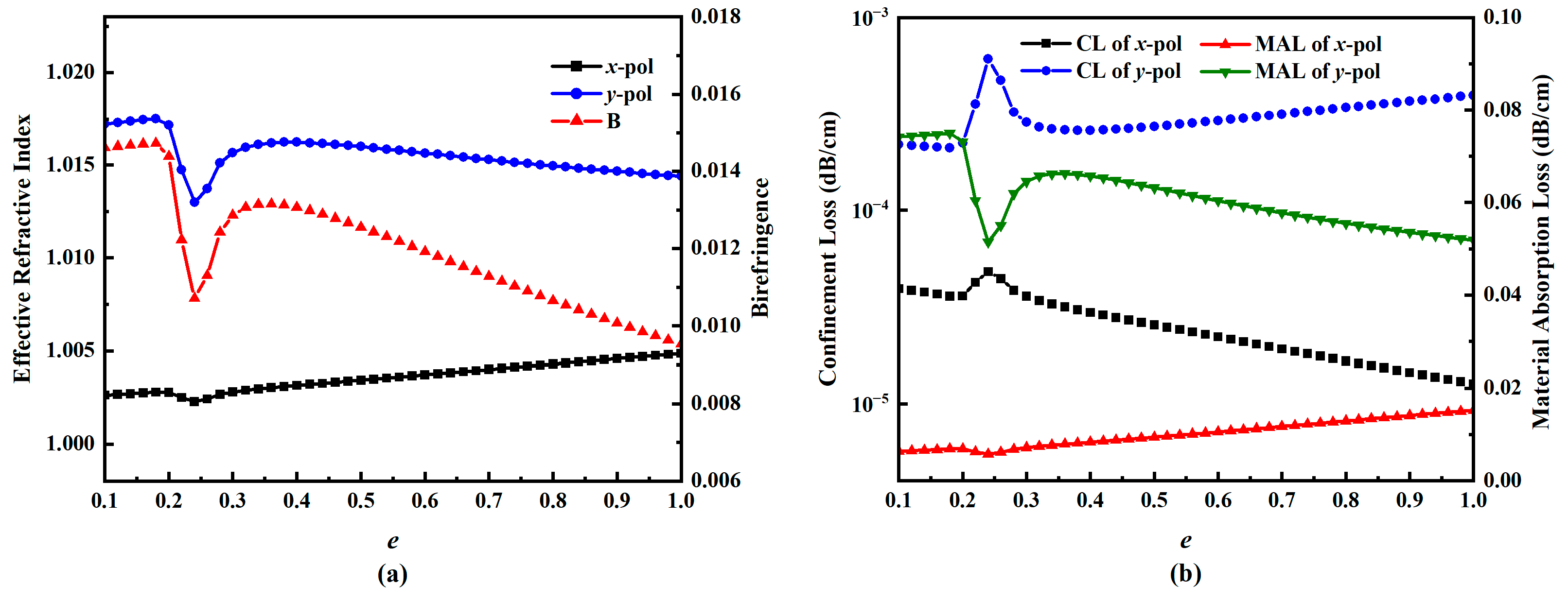
Figure 4a illustrates the variations in the effective refractive indices of x-pol and y-pol as e increases from 0.2 to 0.9. It can be observed from the graph that there is a distinct inflection point around e = 0.25. By considering the numerical values of da and d, along with the geometric relationship, it can be deduced that this point corresponds to the tangential points between the ends of the ellipse and the two central support columns. Subsequently, the effective refractive index of y-pol increases significantly faster than that of x-pol, leading to an increase in birefringence. However, shortly after, the effective refractive index of y-pol either stabilizes or gradually decreases, while that of x-pol steadily increases, resulting in a rapid decrease in birefringence. This phenomenon may be attributed to the increasing symmetry of the core region as e approaches 1, leading to a reduction in birefringence. In Figure 4b, the CL and MAL of the fiber are depicted. Similarly, near the point of tangency, which is around e = 0.25, both the CL and MAL exhibit a distinct turning point, but y-pol is more sensitive to changes in the pole. Pursuing high birefringence and low loss is the focus of the research. When the value of e exceeds 0.3, the birefringence begins to decrease, and the MAL of x-pol gradually increases. Therefore, a value of e between 0.3 and 0.4 can better balance birefringence and loss.
Figure 5 illustrates the impact of the spacing between the two central support columns in the core of the AR-HCF. From Figure 5a, it can be observed that the variation in d has minimal effect on the effective refractive index of x-pol, whereas y-pol is more sensitive to this change. As d increases from 10 µm to 140 µm, the birefringence initially decreases and then increases. The reason for the inflection point in the variation is due to the tangential contact between the elliptical structure and the two central support columns. At this point, the asymmetry of the core structure decreases compared to before, leading to a reduction in birefringence. In Figure 5b, the losses are depicted, showing an overall decreasing trend as d increases, especially concerning the MAL of y-pol. Therefore, it can be concluded that the variation in d primarily impacts the effective refractive index and the MAL of y-pol.
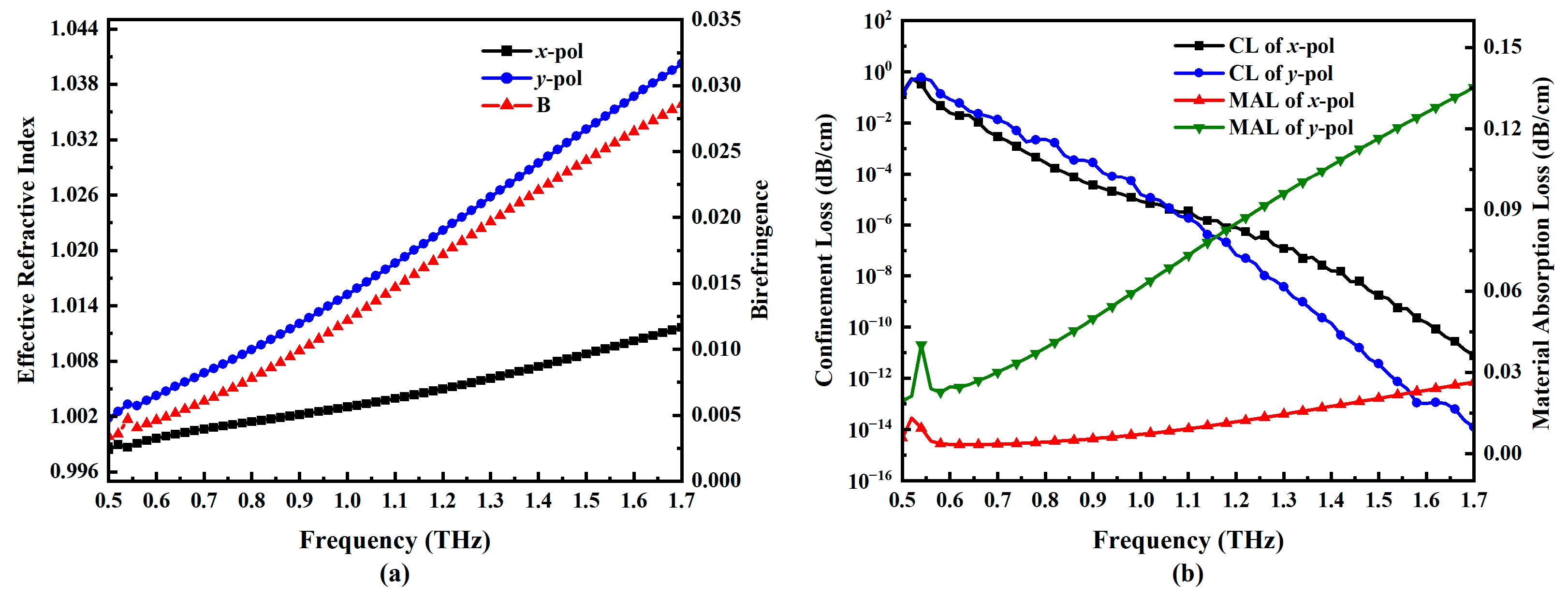
We optimize each structural parameter of the optical fiber and determine the final values as follows: Rs = 1820 µm, g = 70 µm, Rn = 550 µm, t = 6 µm, da = 160 µm, e = 0.36, R = 1850 µm, d = 95 µm. We study the polarization characteristics of the AR-HCF structure at different terahertz frequencies, as shown in Figure 6. Within the frequency range of 0.5~1.7 THz, as the frequency increases, the effective refractive indices of x-pol and y-pol also increase. The sensitivity of y-pol to frequency changes is higher, with a growth rate greater than x-pol, leading to an increase in birefringence with frequency. Figure 6b illustrates the variation in losses with frequency. The CL is inversely related to the operating frequency. As the frequency increases, the CL can decrease from 10−1 dB/cm to 10−14 dB/cm. Additionally, the rate of CL reduction for y-pol is greater than that for x-pol. After 1.4 THz, the AR-HCF exhibits single-polarization characteristics. Meanwhile, the MAL increases with the operating frequency. For frequencies below 1.14 THz, the MAL of x-pol remains below 10−3 dB/cm. Although the numerical value and growth rate of y-pol’s MAL are higher than that of x-pol, its losses at 1.34 THz are still below 10−2 dB/cm, similar to other structural fibers. Compared to existing optical fiber structures, this structure has significant advantages, with the lowest CL and MAL, achieving birefringence greater than 10−2 and demonstrating favorable optical characteristics.

4. Discussion of the Proposed AR-HCF

Figure 7 explores the impact of variations in certain structural parameters on the birefringence and losses of the fiber during its fabrication. It primarily investigates the effects of the core radius, the cladding thickness, and the central pillar thickness. It can be observed that within a significant range of differences, Rs and g have a relatively small influence on the fiber’s birefringence, while t has a pronounced effect. Birefringence increases with an increase in t. When t goes from 2 µm to 12 µm, the birefringence multiplies by nearly a factor of 8. Similarly, the MAL shows lower sensitivity to changes in Rs and g but exhibits a positive correlation with t. The CL is negatively correlated with the size of these three structural parameters over a larger range. Therefore, careful attention should be paid to the magnitude of t during the fabrication of the fiber. On the other hand, it is also possible to achieve higher birefringence by altering the value of t.
The final investigation focused on the impact of bending on the structure of the fiber. As shown in Figure 8a, bending in the x-direction resulted in a certain degree of variation in the birefringence of the AR-HCF. The primary reason for this is that x-direction bending affects the effective refractive index of the x-pol mode, while the effective refractive index of the y-pol mode remains relatively unchanged. Figure 8b illustrates the bending loss and MAL. When the bending radius is less than 12 cm, the bending loss exceeds 10−4 dB/cm. This is mainly due to the disruption of the symmetrical structure of the AR-HCF caused by bending, leading to a significantly higher CL compared to a straight fiber. However, as the bending radius increases, the bending loss steadily decreases. The value of the MAL fluctuates during the bending process but consistently remains below 10−3 dB/cm. Similarly, the effects of y-direction bending are depicted in Figure 8c,d. Unlike the effects of x-direction bending, y-direction bending has a greater impact on the central pillar and elliptical tube, resulting in a more significant effect on birefringence. Compared to x-direction bending, the y-direction bending loss needs to exceed 10−3 dB/cm when the bending radius is greater than 34 cm. The MAL consistently stays at 10−3 dB/cm.
Comparisons between recent research on AR-HCFs and the proposed structure in this paper are presented in Table 1. It can be observed that the AR-HCF introduced in this study exhibits significant advantages in birefringence, the CL, the MAL, and bending loss compared to previous studies. The fiber proposed in this paper achieves higher birefringence with lower losses, representing a significant breakthrough in AR-HCF research.
The feasibility of fiber fabrication for this structure has been analyzed. The manufacturing of AR-HCFs typically involves methods such as stacking [41], drilling [36], and extrusion [42]. The outer cladding tube structure of the optical fiber is relatively simple and can be achieved through stacking or drilling methods. On the other hand, the two central pillars and the elliptical structure in the core section can be prepared using drilling or extrusion methods. In 2012, Lian et al. successfully fabricated two ultra-thin central pillars in the core section using the extrusion method [43]. Additionally, 3D printing technology can also be employed to produce more precise or complex optical fibers. In 2023, Lu et al. successfully fabricated a core structure similar to the proposed optical fiber using 3D printing technology, demonstrating the feasibility of manufacturing this type of AR-HCF [31].

5. Conclusions

In conclusion, this paper proposes a high-birefringence, low-loss AR-HCF. By introducing two central support pillars and an elliptical tube structure into the fiber core, the structural symmetry of the fiber is greatly disrupted, allowing for high birefringence while maintaining low loss. Compared to previously reported structures, it has significant advantages in terms of birefringence and loss. By optimizing the structural parameters of the fiber, the birefringence at a frequency of 1 THz is 1.22 × 10⁻², with a CL of 8.34 × 10⁻⁶ dB/cm and an MAL of 7.17 × 10⁻³ dB/cm. Additionally, this AR-HCF exhibits single-polarization characteristics at frequencies greater than 1.4 THz. Furthermore, when the bending radius of the fiber is larger than 12 cm, the bending loss is less than 1.36 × 10⁻³ dB/cm, demonstrating its bend-resistant properties. This work provides a new design approach to low-loss, high-birefringence AR-HCFs. It is believed that the AR-HCF has potential application value in optical communication systems.

Author Contributions

Conceptualization, Y.D., R.Z. and J.Z.; Methodology, Y.D. and D.Z.; Software, Y.D., D.Z. and R.Z.; Writing—original draft, Y.D.; Writing—review & editing, J.Z.; Visualization, D.Z.; Supervision, H.Z.; Project administration, H.Z.; Funding acquisition, H.Z. All authors have read and agreed to the published version of the manuscript.

Funding

This work was supported by the National Natural Science Foundation of China under Grant Nos. 61405096 and 61504058 and the introduction of research talent; the Research Fund of Nanjing University of Posts and Telecommunications (NY214158); the open fund of the Laboratory of Solid State Microstructures, Nanjing University (M28035); and the open fund of the State Key Laboratory of Transient Optics and Photonics, the Chinese Academy of Sciences (SKLST201404). We would like to express our sincere thanks to the above organizations.

Data Availability Statement

The data underlying the results presented in this paper are not publicly available at this time but may be obtained from the authors upon reasonable request.

Conflicts of Interest

The authors declare no conflicts of interest.

References

  1. Hoshina, H.; Sasaki, Y.; Hayashi, A.; Otani, C.; Kawase, K. Noninvasive mail inspection system with terahertz radiation. Appl. Spectrosc. 2009, 63, 81–86. [Google Scholar] [CrossRef]
  2. Pawar, A.Y.; Sonawane, D.D.; Erande, K.B.; Derle, D.V. Terahertz technology and its applications. Drug Invent. Today 2013, 5, 157–163. [Google Scholar] [CrossRef]
  3. Lewis, R.A. A review of terahertz sources. J. Phys. D Appl. Phys. 2014, 47, 374001. [Google Scholar] [CrossRef]
  4. Bergeron, A.; Marchese, L.; Savard, É.; LeNoc, L.; Bolduc, M.; Terroux, M.; Dufour, D.; Tang, D.; Châteauneuf, F.; Jerominek, H. Resolution capability comparison of infrared and terahertz imagers. In Proceedings of the Millimetre Wave and Terahertz Sensors and Technology IV, Prague, Czech Republic, 19–20 September 2011; SPIE: Bellingham, WA, USA, 2011; Volume 8188. [Google Scholar]
  5. Li, R.; Li, C.; Li, H.; Wu, S.; Fang, G. Study of automatic detection of concealed targets in passive terahertz images for intelligent security screening. IEEE Trans. Terahertz Sci. Technol. 2018, 9, 165–176. [Google Scholar] [CrossRef]
  6. Yan, Z.; Zhu, L.-G.; Meng, K.; Huang, W.; Shi, Q. THz medical imaging: From in vitro to in vivo. Trends Biotechnol. 2022, 40, 816–830. [Google Scholar] [CrossRef]
  7. Li, Y.; Shen, X.A.; Ewing, R.L.; Li, J. Terahertz spectroscopic material identification using approximate entropy and deep neural network. In Proceedings of the 2017 IEEE National Aerospace and Electronics Conference (NAECON), Dayton, OH, USA, 27–30 June 2017. [Google Scholar]
  8. Chen, Z.; Han, C.; Wu, Y.; Li, L.; Huang, C.; Zhang, Z.; Wang, G.; Tong, W. Terahertz wireless communications for 2030 and beyond: A cutting-edge frontier. IEEE Commun. Mag. 2021, 59, 66–72. [Google Scholar] [CrossRef]
  9. El Ghzaoui, M.; Das, S. Data transmission with terahertz communication systems. In Emerging Trends in Terahertz Solid-State Physics and Devices: Sources, Detectors, Advanced Materials, and Light-Matter Interactions; Springer: Berlin/Heidelberg, Germany, 2020; pp. 121–141. [Google Scholar]
  10. Liu, J.; Fan, L.; Ku, J.; Mao, L. Absorber: A novel terahertz sensor in the application of substance identification. Opt. Quantum Electron. 2016, 48, 80. [Google Scholar] [CrossRef]
  11. Wang, K.; Mittleman, D.M. Metal wires for terahertz wave guiding. Nature 2004, 432, 376–379. [Google Scholar] [CrossRef]
  12. Bingham, A.; Zhao, Y.; Grischkowsky, D. THz parallel plate photonic waveguides. Appl. Phys. Lett. 2005, 87, 051101. [Google Scholar] [CrossRef]
  13. Roze, M.; Ung, B.; Mazhorova, A.; Walther, M.; Skorobogatiy, M. Suspended core subwavelength fibers: Towards practical designs for low-loss terahertz guidance. Opt. Express 2011, 19, 9127–9138. [Google Scholar] [CrossRef]
  14. Saeedkia, D.; Safavi-Naeini, S. Modeling and analysis of a multilayer dielectric slab waveguide with applications in edge-coupled terahertz photomixer sources. J. Light. Technol. 2007, 25, 432–439. [Google Scholar] [CrossRef]
  15. Yakasai, I.K. Pg Emeroylariffion Abas, and Feroza Begum. Review of porous core photonic crystal fibers for terahertz waveguiding. Optik 2021, 229, 166284. [Google Scholar] [CrossRef]
  16. Li, L.; Lin, D.; Meng, F.; Zhao, Y.; Cui, Y.; Cao, Y.; Liu, H.; Mu, H.; Niu, Y.; He, J.; et al. Investigation on low-loss hollow-core anti-resonant terahertz fiber. Appl. Opt. 2023, 62, 5778–5785. [Google Scholar] [CrossRef]
  17. Hong, Y.; Bottrill, K.R.; Bradley, T.D.; Sakr, H.; Jasion, G.T.; Harrington, K.; Poletti, F.; Petropoulos, P.; Richardson, D.J. Low-Latency WDM Intensity-Modulation and Direct-Detection Transmission Over > 100 km Distances in a Hollow Core Fiber. Laser Photonics Rev. 2021, 15, 2100102. [Google Scholar] [CrossRef]
  18. Kühlthau, T.; Chen, B.; Kleem, G.; Graf, T.; Ahmed, M.A. Design, production, and characterization of a Large-Mode Area tubular Inhibited-Coupling Guiding Hollow-Core Fiber with low dispersion. In Proceedings of the European Conference on Lasers and Electro-Optics, Optica Publishing Group, Munich, Germany, 26–30 June 2023. [Google Scholar]
  19. Fu, Q.; Davidson, I.A.; Mousavi, S.M.A.; Mulvad, H.C.H.; Wheeler, N.V.; Xu, L.; Poletti, F.; Richardson, D.J. Hollow-Core Fiber: Breaking the Nonlinearity Limits of Silica Fiber in Long-Distance Green Laser Pulse Delivery. Laser Photonics Rev. 2024, 18, 2201027. [Google Scholar] [CrossRef]
  20. Habib, M.S.; Bang, O.; Bache, M. Low-loss single-mode hollow-core fiber with anisotropic anti-resonant elements. Opt. Express 2016, 24, 8429–8436. [Google Scholar] [CrossRef]
  21. Poletti, F. Nested antiresonant nodeless hollow core fiber. Opt. Express 2014, 22, 23807–23828. [Google Scholar] [CrossRef]
  22. Cregan, R.F.; Mangan, B.J.; Knight, J.C.; Birks, T.A.; Russell, P.S.J.; Roberts, P.J.; Allan, D.C. Single-mode photonic band gap guidance of light in air. Science 1999, 285, 1537–1539. [Google Scholar] [CrossRef]
  23. Chen, X.; Li, M.-J.; Venkataraman, N.; Gallagher, M.T.; Wood, W.A.; Crowley, A.M.; Carberry, J.P.; Zenteno, L.A.; Koch, K.W. Highly birefringent hollow-core photonic bandgap fiber. Opt. Express 2004, 12, 3888–3893. [Google Scholar] [CrossRef]
  24. Fini, J.M.; Nicholson, J.W.; Mangan, B.; Meng, L.; Windeler, R.S.; Monberg, E.M.; DeSantolo, A.; DiMarcello, F.V.; Mukasa, K. Polarization maintaining single-mode low-loss hollow-core fibres. Nat. Commun. 2014, 5, 5085. [Google Scholar] [CrossRef]
  25. Roberts, P.J.; Couny, F.; Sabert, H.; Mangan, B.J.; Williams, D.P.; Farr, L.; Mason, M.W.; Tomlinson, A.; A Birks, T.; Knight, J.C.; et al. Ultimate low loss of hollow-core photonic crystal fibres. Opt. Express 2005, 13, 236–244. [Google Scholar] [CrossRef]
  26. Fokoua, E.R.N.; Mousavi, S.M.A.; Jasion, G.T.; Richardson, D.J.; Poletti, F. Loss in hollow-core optical fibers: Mechanisms, scaling rules, and limits. Adv. Opt. Photonics 2023, 15, 1–85. [Google Scholar] [CrossRef]
  27. Ding, W.; Wang, Y.-Y.; Gao, S.-F.; Wang, M.-L.; Wang, P. Recent progress in low-loss hollow-core anti-resonant fibers and their applications. IEEE J. Sel. Top. Quantum Electron. 2019, 26, 1–12. [Google Scholar] [CrossRef]
  28. Ding, W.; Wang, Y.-Y. Hybrid transmission bands and large birefringence in hollow-core anti-resonant fibers. Opt. Express 2015, 23, 21165–21174. [Google Scholar] [CrossRef]
  29. Mousavi, S.A.; Sandoghchi, S.R.; Richardson, D.J.; Poletti, F. Broadband high birefringence and polarizing hollow core antiresonant fibers. Opt. Express 2016, 24, 22943–22958. [Google Scholar] [CrossRef]
  30. Hong, Y.F.; Gao, S.F.; Ding, W.; Zhang, X.; Jia, A.Q.; Sheng, Y.L.; Wang, P.; Wang, Y.Y. Highly Birefringent Anti-Resonant Hollow-Core Fiber with a Bi-Thickness Fourfold Semi-Tube Structure. Laser Photonics Rev. 2022, 16, 2100365. [Google Scholar] [CrossRef]
  31. Xue, L.; Sheng, X.; Mu, Q.; Kong, D.; Wang, Z.; Chu, P.K.; Lou, S. 3D-printed high-birefringence THz hollow-core anti-resonant fiber with an elliptical core. Opt. Express 2023, 31, 26178–26193. [Google Scholar] [CrossRef]
  32. Hasanuzzaman, G.; Iezekiel, S.; Markos, C.; Habib, S. Hollow-core fiber with nested anti-resonant tubes for low-loss THz guidance. Opt. Commun. 2018, 426, 477–482. [Google Scholar] [CrossRef]
  33. Yang, S.; Sheng, X.; Zhao, G.; Lou, S.; Guo, J. 3D printed effective single-mode terahertz antiresonant hollow core fiber. IEEE Access 2021, 9, 29599–29608. [Google Scholar] [CrossRef]
  34. Lu, Y.; Han, Z.; Tian, F.; Zeng, Z.; Chen, Y.; Xiu, Z.; Liu, S.; Liu, C.; Yang, X.; Zhang, J. A THz fiber polarization splitter based on anti-resonant hollow-core fiber with the asymmetric dual-suspended cores. Front. Phys. 2023, 11, 1189506. [Google Scholar] [CrossRef]
  35. Hasan, M.R.; Islam, M.A.; Anower, M.S.; Razzak, S.M.A. Low-loss and bend-insensitive terahertz fiber using a rhombic-shaped core. Appl. Opt. 2016, 55, 8441–8447. [Google Scholar] [CrossRef]
  36. Yan, S.; Lou, S.; Wang, X.; Zhao, T.; Zhang, W. High-birefringence hollow-core anti-resonant THz fiber. Opt. Quantum Electron. 2018, 50, 162. [Google Scholar] [CrossRef]
  37. Mollah, M.A.; Habib, M.S.; Habib, M.S. Novel hollow-core asymmetric conjoined-tube anti-resonant fiber for low-loss THz wave guidance. Osa Contin. 2020, 3, 1169–1176. [Google Scholar] [CrossRef]
  38. Mollah, M.A.; Rana, S.; Subbaraman, H. Polarization filter realization using low-loss hollow-core anti-resonant fiber in THz regime. Results Phys. 2020, 17, 103092. [Google Scholar] [CrossRef]
  39. Sun, S.; Shi, W.; Sheng, Q.; Yan, Z.; Zhang, S.; Zhang, J.; Shi, C.; Zhang, G.; Yao, J. Polarization-maintaining terahertz anti-resonant fibers based on mode couplings between core and cladding. Results Phys. 2021, 25, 104309. [Google Scholar] [CrossRef]
  40. Liu, Z.; Wen, J.; Zhang, L.; Zhou, Z.; Dong, Y.; Yang, T. Multiple designs with broad applicability for enhancing birefringence in low-loss terahertz HC-ARF. Results Phys. 2023, 52, 106793. [Google Scholar] [CrossRef]
  41. Zhao, X.; Wu, X.; Lan, X.; Luo, J.; Zhang, L.; Li, P.; Xiang, J.; Li, Z.; Cheng, Y. Adjacent nested 4-tube hollow-core anti-resonant fiber. Opt. Commun. 2022, 522, 128631. [Google Scholar] [CrossRef]
  42. Ventura, A.; Hayashi, J.G.; Cimek, J.; Jasion, G.; Janicek, P.; Ben Slimen, F.; White, N.; Fu, Q.; Xu, L.; Sakr, H.; et al. Extruded tellurite antiresonant hollow core fiber for Mid-IR operation. Opt. Express 2020, 28, 16542–16553. [Google Scholar] [CrossRef] [PubMed]
  43. Lian, Z.; Horak, P.; Feng, X.; Xiao, L.; Frampton, K.; White, N.; Tucknott, J.A.; Rutt, H.; Payne, D.N.; Stewart, W.; et al. Nanomechanical optical fiber. Opt. Express 2012, 20, 29386–29394. [Google Scholar] [CrossRef] [PubMed]
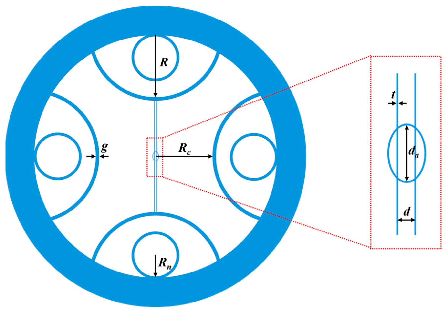
Figure 1. Cross-sectional structure of the proposed AR-HCF.
Electronics 13 02382 g001
Figure 2. The electric field distributions of x-pol mode and y-pol mode for AR-HCF at 1 THz.
Electronics 13 02382 g002
Figure 3. (a) The effective refractive indices of the x-pol and y-pol core modes and B, and (b) CL and MAL of the x-pol and y-pol core modes when da increases from 100 to 200 µm.
Electronics 13 02382 g003
Figure 4. (a) The effective refractive indices of the x-pol and y-pol core modes and B, and (b) CL and MAL of the x-pol and y-pol core modes when e increases from 0.2 to 0.9.
Electronics 13 02382 g004
Figure 5. (a) The effective refractive indices of the x-pol and y-pol core modes and B, and (b) CL and MAL of the x-pol and y-pol core modes when d increases from 10 to 140 µm.
Electronics 13 02382 g005
Figure 6. (a) The effective refractive indices of the x-pol and y-pol core modes and B, and (b) CL and MAL of the x-pol and y-pol core modes when frequency increases from 0.5 to 1.7 THz.
Electronics 13 02382 g006
Figure 7. Birefringence as a function of (a) Rs, (c) g, (e) t, CL, and MAL as a function of (b) Rs, (d) g, (f) t at 1 THz.
Electronics 13 02382 g007
Figure 8. (a) Birefringence, (b) bending loss, and MAL when bent in the x-direction. (c) Birefringence, (d) bending loss, and MAL when bent in the y-direction.
Electronics 13 02382 g008
Table 1. Comparison of recent research on AR-HCFs.
Optical Fiber StructureBirefringenceCL (dB/cm)MAL (dB/cm)Bending Radius (cm)Bending Loss (dB/cm)Refs
Elliptical tube10−2/0.96//[31]
Double pillars10−12.5 × 10−31.63//[34]
Circular cladding tubes8.7 × 10−42.1 × 10⁻²/152.51 × 10−2[36]
Circular cladding tubes/3.4 × 10−65 × 10−44510−4[32]
Circular cladding tubes10−41.8 × 10−31.6 × 10−3//[38]
Semicircular cladding tubes4 × 10−41.95 × 10⁻²///[39]
Semicircular and circular cladding tubes10−310−310−1302.46 × 10−3[40]
Double pillars and elliptical tube1.22 × 10−28.34 × 10−67.17 × 10−3121.36 × 10−3This paper
Disclaimer/Publisher’s Note: The statements, opinions and data contained in all publications are solely those of the individual author(s) and contributor(s) and not of MDPI and/or the editor(s). MDPI and/or the editor(s) disclaim responsibility for any injury to people or property resulting from any ideas, methods, instructions or products referred to in the content.