Abstract
Controlling access to critical zones by drones is crucial for ensuring safety and efficient operations in various applications. In this research, we propose a strategy for controlling the access of a set of drones to a critical zone using timed automata and UPPAAL. UPPAAL is a model checker and simulator for real-time systems, which allows for the modeling, simulation, and verification of timed automata. Our system consists of six drones, a controller, and a buffer, all modeled as timed automata. We present a formal model capturing the behavior and interactions of these components, considering the constraints of allowing only one drone in the critical zone at a time. Timed automata are a powerful formalism for modeling and analyzing real-time systems, as they can capture the temporal aspects of system behavior. The advantages of using timed automata include the ability to model time-critical systems, analyze safety and liveness properties, and verify the correctness of the system. We design a strategy that involves signaling the approaching drones, preventing collisions, and ensuring orderly access to the critical zone. We utilize UPPAAL for simulating and verifying the system, including the evaluation of properties such as validation properties, safety properties, liveness properties, and absence of deadlocks. However, a limitation of timed automata is that they can become complex and difficult to model for large-scale systems, and the analysis can be computationally expensive as the number of components and behaviors increases. Through simulations and formal verification, we demonstrate the effectiveness and correctness of our proposed strategy. The results highlight the ability of timed automata and UPPAAL to provide reliable and rigorous analysis of drone access control systems. Our research contributes to the development of robust and safe strategies for managing drone operations in critical zones.
1. Introduction
In recent years, the increasing use of drones in various applications has raised the need for effective control mechanisms to ensure safe and efficient operations, particularly in critical zones [1]. Controlling drone access to these zones is crucial for mitigating potential risks and optimizing resource utilization [2,3]. Traditional control approaches often fall short in addressing the dynamic and time-dependent nature of drone operations, necessitating the use of formal methods for modeling, analyzing, and verifying complex drone control strategies [4,5].
It is important to note that the use of formal methods, such as timed automata and UPPAAL modeling, may appear difficult for new users [6,7]. In this work, we tried to simplify the presented notions as much as possible. However, there is still a need to read more content like papers, documentation, and manuals to fully understand and apply these techniques [8,9,10].
Timed automata are a powerful formal modeling language that can capture the real-time aspects and logical behavior of a system. However, it is important to understand that timed automata may not be able to model everything. They are primarily focused on the decision making and control logic of a system, and may not be able to accurately represent the underlying physical dynamics, environmental factors, and other complex aspects of a system’s behavior.
For example, the timed automata model may not be able to capture the influence of various factors, such as navigation errors, meteorological conditions, or noise in control signals. These aspects are more closely related to the physical and environmental interactions of the system, which would require different modeling approaches, such as mathematical models of controlled bodies and their kinematics.
In practice, it is often necessary to use multiple modeling methods and languages to provide a comprehensive representation of a complex system. Depending on the specific goals and requirements of the analysis, different modeling techniques may be more suitable for capturing different aspects of the system. By utilizing a combination of approaches, researchers and engineers can gain a more complete understanding of the system’s behavior and properties, leading to more reliable and robust real-time systems.
Formal methods, rooted in mathematical logic and automata theory, provide systematic approaches for the specification, design, and analysis of systems with rigorous guarantees [11]. These methods offer a means to model and reason about complex systems, taking into account their intricate behaviors, temporal properties, and interactions [12]. By leveraging formal methods, we can develop precise and reliable control strategies that ensure safety, adherence to desired specifications, and avoidance of critical situations [13,14].
In this paper, we propose a novel strategy for controlling drone access to critical zones using timed automata and UPPAAL. Timed automata, an extension of traditional automata, are a powerful modeling formalism for capturing temporal behavior and synchronization in systems. They provide a natural representation of systems with time-dependent aspects, making them well-suited for modeling and analyzing the dynamics of drone operations. With timed automata, we can precisely capture the timing constraints, synchronization requirements, and decision-making processes involved in controlling drone access to critical zones.
To analyze the effectiveness and correctness of our proposed strategy, we utilize UPPAAL, a widely used tool for modeling, simulating, and verifying timed automata systems [15]. UPPAAL offers a user-friendly graphical interface for designing system models, specifying properties of interest, and executing simulations [16]. Additionally, UPPAAL provides powerful verification capabilities, allowing for the formal verification of properties such as safety, liveness, and absence of deadlocks [17]. By employing UPPAAL, we can systematically evaluate the performance and reliability of our proposed strategy, providing empirical evidence of its effectiveness in controlling drone access to critical zones [18].
The main contributions of this research are threefold. First, we present a formal model based on timed automata, which accurately captures the behavior and interactions of drones, a controller, and a buffer. By leveraging the expressive power of timed automata, we can precisely model time-dependent aspects of drone operations and the decision-making process involved in granting access to the critical zone. Second, we propose a signaling mechanism that enables effective communication between approaching drones and the controller, ensuring orderly access and preventing collisions. The strategy allows for the efficient utilization of the critical zone while maintaining safety and avoiding congestion. Lastly, we employ UPPAAL to evaluate the performance and correctness of the proposed strategy. Through simulations and formal verification, we demonstrate the effectiveness and reliability of our approach.
The structure of this paper is as follows: Section 2 provides an overview of related works in the field of controlling drone access to critical zones, highlighting the research gaps that our work addresses. Section 3 introduces timed automata and UPPAAL as the foundation for our modeling and analysis approach. In Section 4, we present the formal system model, describing the components and their interactions. Section 5 presents the simulation scenarios and the results obtained through UPPAAL, including the verification of key properties. Section 6 identifies the main limitations of the use of timed automata for modeling drones. Section 7 provides some discussions. The conclusions of our research, along with future research directions, are discussed in Section 8.
By combining the power of formal methods, the effectiveness of our proposed strategy, and the rigorous analysis provided by UPPAAL, we aim to contribute to the development of robust and reliable control mechanisms for managing drone access to critical zones.
2. Related Works
In recent years, there has been a growing interest in applying formal methods and techniques to analyze and validate unmanned aerial vehicle (UAV) systems. Several papers have made significant contributions in this area. One approach, presented in [19], focuses on the application of formal methods, particularly model checking, to verify the safety and reachability of cooperative UAV teams. The authors propose a novel framework that utilizes Kripke models and model checking to ensure the correct functioning of multiple UAVs in a simulation scenario. In [20], the authors introduce a rigorous framework for analyzing the stability and control characteristics of UAVs. They employ higher-order-logic theorem proving to formalize complex-valued matrices and navigation concepts, overcoming limitations associated with traditional analysis techniques. The paper showcases the application of this framework in safety-critical applications. For multi-UAV systems, ref. [21] proposes a receding horizon task planning method. The authors utilize local linear temporal logic (LTL) specifications and probabilistic model checking to satisfy rich task specifications assigned to each UAV. The method achieves correct plans with reduced computational burden by synthesizing collaboration plans using finite-horizon product systems. The validation of cooperative UAV systems is addressed in [22], where the authors combine co-simulation and formal verification techniques. The paper presents a method that uses co-simulation to analyze system behaviors and formal verification to ensure safety requirements. The findings highlight the effectiveness of the proposed approach in validating UAV cooperative systems.
The use of interactive theorem proving techniques for analyzing UAV dynamics is reviewed in [23]. The paper emphasizes the limitations of traditional analytical and simulation-based methods and highlights the need for formal verification techniques in ensuring correctness and safety. In the domain of multi-UAV systems in agriculture, ref. [24] introduces a formal modeling approach based on discrete event system (DES) theory. The paper presents a systematic procedure for designing supervisory control theory using finite state automata to model UAV states. This approach enables the efficient and reliable operation of UAVs in precision agriculture. A temporal logic-based planning and execution monitoring framework for unmanned aircraft is proposed in [25]. The framework utilizes temporal logic to specify and verify complex mission plans, ensuring compliance with safety and performance requirements. Ref. [26] introduces a comprehensive model for conflict resolution in Unmanned Aircraft Systems (UASs) using service-oriented modeling and Duration Calculus (DC). The model addresses knowledge acquisition considerations and provides a valuable approach for real-time collaborative systems.
In [27], lightweight Duration Calculus (DC) is employed to model conflict resolution in UASs. The paper presents a formal modeling approach using DC to ensure adherence to requirements and absence of deadlocks and unreachable states. Model checking techniques for verifying the interaction among UAV teams in constrained tasks are explored in [28]. The paper demonstrates the feasibility and effectiveness of verifying the correct behavior of UAV teams using linear temporal logic and the SPIN model checker. For efficient requirements and the design validation of decision logic in auto-flight system software, Ref. [29] applies model-based safety assessment (MBSA) techniques. The paper utilizes fault modeling and automatic cut-set extraction to analyze the autoland system of a UAV. Finally, a fleet management approach for UAVs operating in confined indoor spaces is proposed in [30]. The paper presents a novel solution using Timed Game formulation and Winning Strategy controller synthesis, considering operational constraints and collision avoidance requirements. In conclusion, the papers discussed in this section demonstrate a wide range of formal methods and techniques applied to analyze and validate different aspects of UAV systems, including safety, stability, control, cooperation, conflict resolution, and mission planning. These contributions provide valuable insights and advancements in the field of UAV technology, paving the way for the development of reliable and efficient UAV systems in various applications. The content of this section is summarized in Table 1.

Table 1.
Summary of related work.
3. Timed Automata and UPPAAL
Timed automata and the UPPAAL tool provide powerful formal modeling and verification capabilities for real-time systems. Timed automata extend traditional automata models with the ability to represent the passage of time and timing constraints. UPPAAL, on the other hand, is a popular tool that allows for modeling, simulating, and verifying timed automata-based systems. In this section, we will explore the concepts of timed automata and provide an overview of the UPPAAL tool.
3.1. Timed Automata
Timed automata are formal models that extend traditional finite-state automata with the notion of time. They are particularly suited for modeling and analyzing systems with time-dependent behavior, such as real-time embedded systems, communication protocols, and software systems with timing constraints.
A timed automaton consists of states, transitions, and clocks. The clocks in timed automata are used to model the passage of time and can be reset or tested against timing constraints during transitions. The transitions in a timed automaton are labeled with actions and can specify timing constraints on the clocks. By allowing the explicit representation of time and timing constraints, timed automata enable the modeling and analysis of real-time system behaviors.
Formally, a timed automaton is defined as a tuple , where
- L is a finite set of locations or states;
- is the set of initial locations;
- X is a finite set of clocks;
- C is a finite set of constraints over clocks;
- E is a set of edges or transitions labeled with actions and timing constraints.
The behavior of a timed automaton is defined by its execution paths, which represent sequences of locations and transitions. The execution paths are subject to timing constraints specified by the clocks and constraints. The clocks can be reset or incremented during transitions, and the constraints restrict the possible values of the clocks at each state.
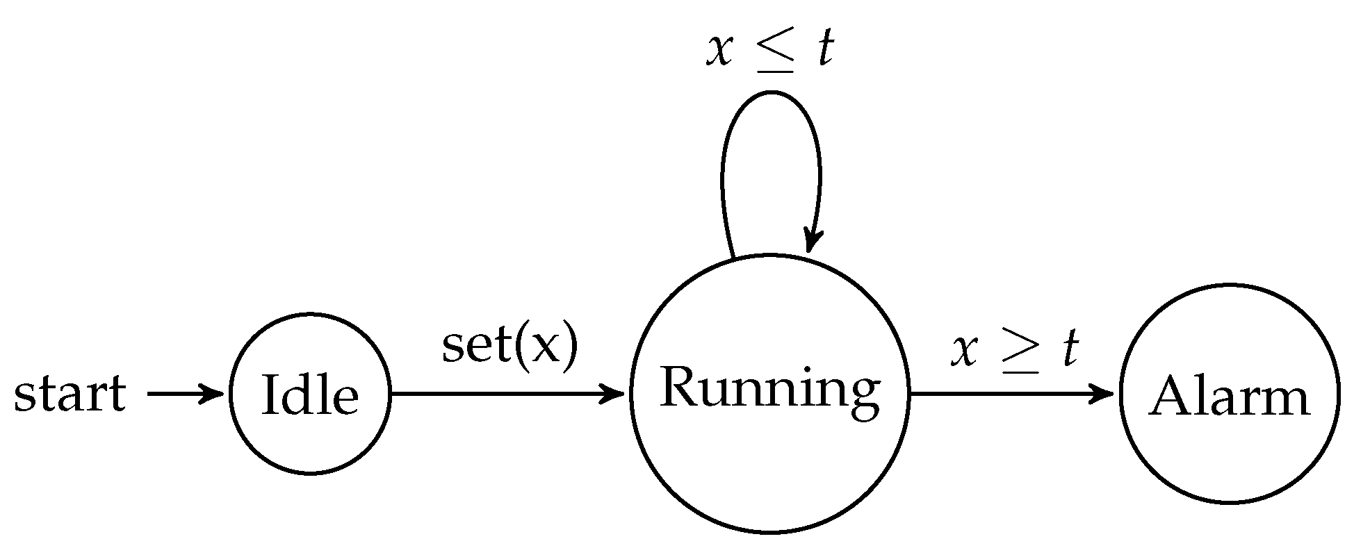
To illustrate the concept of timed automata, consider a simple example of a timer. Figure 1 shows a timed automaton representation of a timer that can be set to a desired duration and will trigger an alarm once the time has elapsed.
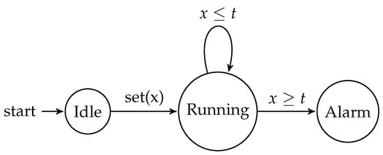
Figure 1.
Timed automaton for a timer.
In this example, the timed automaton has three states: Idle, Running, and Alarm. The clock variable x is used to keep track of the elapsed time. When the timer is set (the transition), the automaton moves from the Idle state to the Running state. While in the Running state, the automaton remains in the same state as long as the clock x is less than or equal to the desired duration t. Once the clock x reaches the duration t, the automaton transitions to the Alarm state, triggering the alarm. While this model captures the core functionality of a timer, there are often additional requirements and features that may be needed in more complex applications.
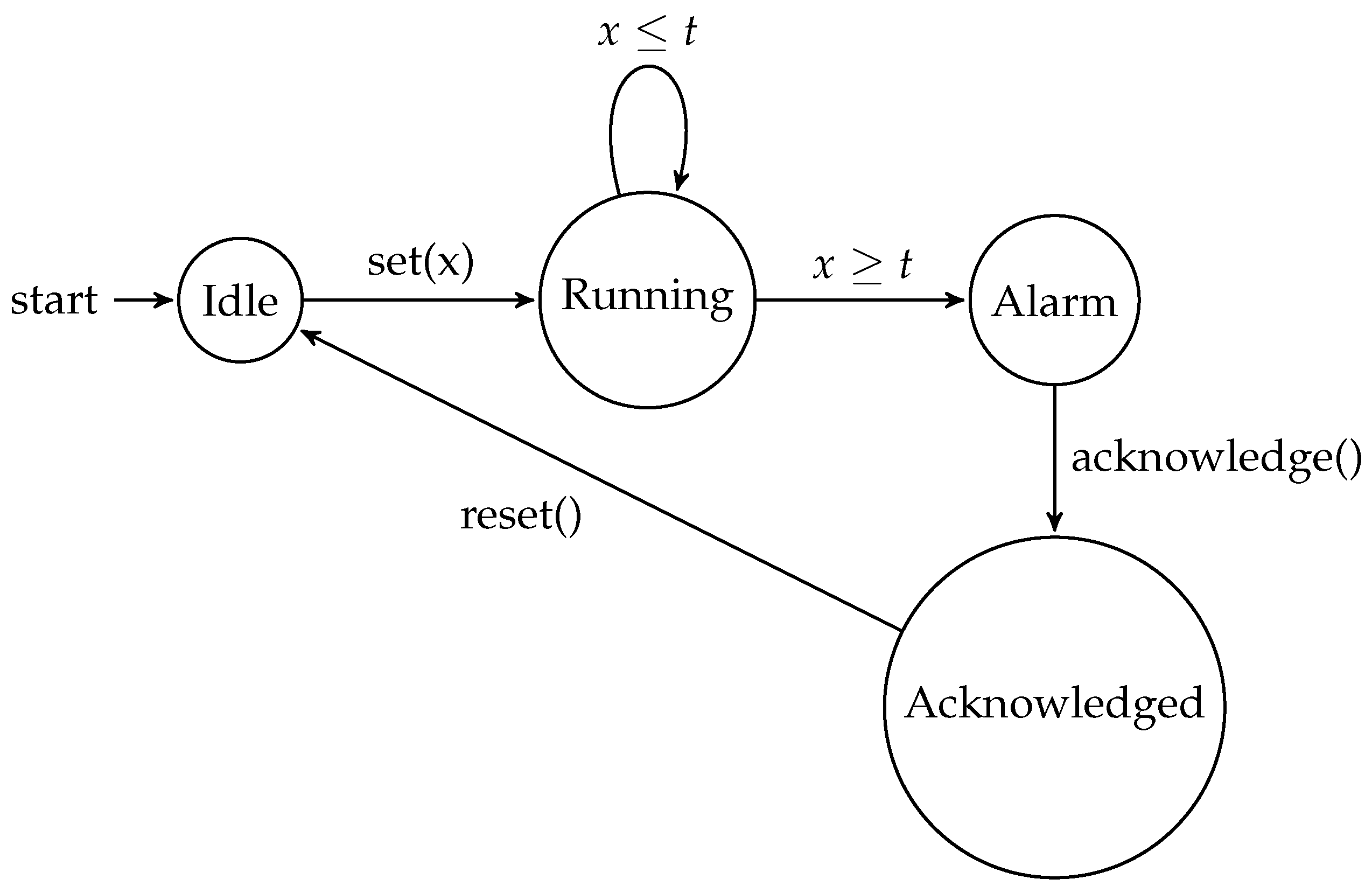
To illustrate a more advanced timer automaton, let us consider an extension of the previous example. Figure 2 shows a timed automaton that includes additional states and transitions to handle the acknowledgment and reset of the alarm.

Figure 2.
Timed automaton for an advanced timer.
The additional functionality provided by the advanced timer automaton allows for more complex and nuanced timer behavior to be modeled. Some key differences between the basic and advanced timer automata include the following:
- Alarm Acknowledgment: The advanced automaton introduces the “Acknowledged” state, which represents the state where the user has responded to the alarm. This allows the model to capture the user’s interaction with the timer and the process of acknowledging the alarm.
- Timer Reset: In the advanced automaton, the timer can be reset from the “Acknowledged” state, allowing the user to prepare the timer for the next cycle of operation. This is an important feature in applications where the timer is used for monitoring or notification purposes.
- Timed Traces: The timed traces for the advanced automaton include additional scenarios, such as the alarm being acknowledged but not reset and the timer never reaching the threshold. These traces provide a more comprehensive understanding of the timer’s behavior in different situations.
By incorporating these additional features, the advanced timer automaton can be used to model more complex timer-based systems, where the ability to acknowledge and reset the timer is a crucial requirement. This level of detail and flexibility in the timed automaton model can be valuable in the design and analysis of real-world timer-based applications.
Some examples of timed traces for the advanced timer automaton include the following:
- Normal Operation:
- Timer Reset before Alarm:
- Timer Never Reaches Threshold:
- Alarm Acknowledged but Not Reset:
3.2. UPPAAL
UPPAAL is a widely used tool for modeling, simulating, and verifying real-time systems based on timed automata. It provides a graphical user interface (GUI) that allows users to construct system models using timed automata and specify properties of interest for verification. UPPAAL’s verification engine then analyzes the model to check if the specified properties hold. The UPPAAL tool supports the modeling of complex real-time systems through the composition of multiple timed automata, allowing for the representation of concurrent and distributed behaviors. It offers a rich set of features, including the following:
- Graphical Interface: UPPAAL provides a user-friendly graphical interface that facilitates the construction and visualization of timed automata models. Users can define the states, transitions, clocks, and timing constraints using a visual representation.
- Simulation Capabilities: UPPAAL allows users to simulate the behavior of the modeled system, providing insights into its dynamic execution. Simulation can help validate the model and gain a better understanding of the system’s timing characteristics.
- Property Specification: UPPAAL supports the specification of various properties that can be verified against the model. Properties can be expressed using temporal logics such as Linear Temporal Logic (LTL) or Computation Tree Logic (CTL). These properties define the desired system behaviors or requirements to be checked.
- Model Checking: UPPAAL’s verification engine performs model checking to analyze the timed automata model and determine if the specified properties hold. It explores the state space of the model, considering the timing constraints and interactions between timed automata, to verify the properties of interest.
- Counterexample Generation: If a property is violated, UPPAAL can generate counterexamples that illustrate the execution paths leading to the violation. These counterexamples aid in diagnosing and debugging the system, helping users understand the causes of property violations.
UPPAAL has been widely used for the formal verification of real-time systems in various domains, including automotive systems, communication protocols, and embedded software. Its ability to handle complex timing constraints and its support for both modeling and verification make it a valuable tool for ensuring the correctness and timeliness of real-time systems.
UPPAAL is particularly useful for non-experts and researchers who are not familiar with timed automata, as it provides a user-friendly interface and intuitive visualization of the system models. The graphical representation of timed automata makes it easier for users to understand and interact with the system, even if they are not experts in formal verification techniques. Additionally, the simulation capabilities of UPPAAL allow users to observe the dynamic behavior of the system, which can be helpful in validating the model and identifying potential issues before conducting formal verification.
For researchers who are familiar with timed automata, UPPAAL offers a powerful set of tools for exploring and analyzing real-time systems. The ability to specify complex properties using temporal logics and the model checking capabilities of UPPAAL enable researchers to rigorously verify the correctness and performance of their system designs. The counterexample generation feature is particularly useful for researchers, as it provides detailed information about the causes of property violations, facilitating the debugging and refinement of the system models.
In summary, UPPAAL is a valuable tool for both non-experts and researchers in the field of real-time systems, as it combines intuitive modeling capabilities with powerful verification features. Its wide adoption and success in various application domains demonstrate its effectiveness in ensuring the reliability and timeliness of complex real-time systems.
3.3. Formal Verification
Timed automata provide a formal foundation for reasoning about the timing aspects of real-time systems. They can be analyzed using various techniques, such as model checking, to verify properties related to timing, synchronization, and reachability. Formal verification is a rigorous approach to verifying the correctness of a system or software by applying mathematical techniques. It involves constructing a mathematical model of the system and using formal methods to reason about its behavior and properties. The goal of formal verification is to provide mathematical guarantees that a system satisfies its desired properties, such as safety, liveness, and security. Formal verification techniques can be broadly classified into two categories: model checking and theorem proving.
3.3.1. Model Checking
Model checking is a formal verification technique that involves exhaustively exploring the state space of a system model to determine if a given property holds in all possible states and under all possible behaviors. It operates by constructing a finite representation of the state space of the model and systematically checking the property for each state. Given a system model and a property , model checking verifies if , meaning that the property holds in all states of the model. Model checking can be performed using various algorithms and tools, such as UPPAAL, which explore the state space and evaluate the properties for each state.
Model checking is particularly useful for non-experts and researchers who want to verify the correctness of their real-time systems. It provides a systematic and automated way to explore the behavior of the system and check if it satisfies the desired properties. The use of a model checker like UPPAAL allows users to create a graphical representation of the system, which can be more intuitive and easier to understand than working with the mathematical formalism of timed automata directly. By running the model checker on their system model, users can quickly identify any potential issues or violations of the specified properties, and then use the counterexamples provided to debug and refine their system design.
3.3.2. Theorem Proving
Theorem proving is another formal verification technique that involves using mathematical logic and proof techniques to establish the correctness of a system. It relies on constructing formal proofs based on axioms, inference rules, and logical reasoning. Theorem proving requires human interaction and expertise to guide the proof construction. In theorem proving, the properties of interest are expressed using formal logics, such as propositional logic, first-order logic, or higher-order logic. Theorems are then established by constructing a formal proof using logical rules and inference steps. Automated theorem provers, such as HOL, Isabelle, and Coq, provide tools and environments for interactive and automated theorem proving.
While theorem proving is a powerful technique for formal verification, it is generally more complex and requires a deeper understanding of mathematical logic and proof techniques. Non-experts may find it challenging to directly engage with theorem proving tools and construct the necessary formal proofs. However, for researchers who are familiar with formal methods and logical reasoning, theorem proving can be a valuable approach for verifying the correctness of their real-time systems, especially when dealing with complex properties or systems where model checking may not be sufficient. The use of automated theorem provers can help reduce the burden of proof construction, but it still requires a significant level of expertise to effectively utilize these tools.
3.4. Symbolic Execution
Symbolic execution is a technique used in formal verification and software testing to analyze the behavior of a program or system without executing it concretely. It involves representing program variables symbolically as mathematical expressions and performing computations on these expressions to explore different execution paths. This technique explores the program’s control flow by systematically evaluating the program’s instructions and tracking the symbolic values of variables. Imagine you are following a recipe to bake a cake. In symbolic execution, instead of using actual ingredients, you would use variables that represent the ingredients, like “flour” or “eggs”. You would then perform the steps in the recipe using these symbolic variables and see how the cake turns out, without actually baking it. This allows for the analysis of different execution paths and the generation of test inputs that cover various program behaviors. For example, if the recipe calls for adding “flour” and “eggs”, symbolic execution would explore what happens if you add different amounts of flour and eggs, or even different types of flour and eggs. This helps identify potential issues or unexpected behaviors in the program.
Symbolic execution can be used to detect bugs, verify properties, and generate test cases automatically. Imagine you are building a calculator app. Symbolic execution would allow you to check that the app performs calculations correctly for all possible input values, without having to try every single combination. This helps ensure that the app works as intended and catch any bugs before releasing it to users. By representing variables symbolically, symbolic execution enables the analysis of all possible inputs and program states. It can identify potential issues, such as constraint violations, infeasible paths, or violations of desired properties. Continuing the calculator app example, symbolic execution could identify cases where the app might crash or give incorrect results, even for inputs that you had not thought to test. However, symbolic execution can suffer from path explosion, where the number of possible execution paths grows exponentially, making it computationally expensive for large programs. Imagine the calculator app became more complex, with many different functions and options. The number of possible ways to use the app would grow rapidly, making it challenging for symbolic execution to analyze every single case. Researchers are working on ways to make symbolic execution more efficient for complex programs.
3.5. Types of Properties
In formal verification, different types of properties can be verified depending on the desired system properties and requirements. Some common types of properties include the following:
- Safety Properties: Safety properties specify conditions that should always hold during system execution. They are concerned with the absence of errors, violations, or undesirable states. For example, a safety property could state that a system should never enter a deadlock state or violate certain safety constraints.
- Liveness Properties: Liveness properties specify conditions that should eventually be satisfied during system execution. They guarantee progress or the absence of livelocks. Liveness properties ensure that certain desirable states or behaviors will occur infinitely often. For example, a liveness property could state that a system should eventually respond to every request.
- Invariant Properties: Invariant properties specify conditions that remain true throughout the system execution. They define properties that must hold at all states of the system. Invariant properties can be used to capture system invariants, the preservation of resources, or inductive properties.
- Temporal Properties: Temporal properties specify how system behavior evolves over time. They describe patterns or sequences of states and events. Temporal logics, such as Linear Temporal Logic (LTL) and Computation Tree Logic (CTL), are commonly used to express temporal properties. These properties can capture ordering requirements, event occurrences, and temporal relationships between system components.
These are just a few examples of the types of properties that can be verified using formal verification techniques. Different types of properties are suitable for different types of systems and can provide insights into various aspects of system behavior and correctness.
In the context of formal verification, the types of properties that can be verified are closely tied to the specific requirements and goals of the system under analysis. While the formal definitions of safety, liveness, invariant, and temporal properties provide a rigorous mathematical foundation, it is important to understand these concepts in simpler terms as well.
Safety properties essentially ensure that the system will never enter an undesirable or “unsafe” state, such as a deadlock or a violation of critical constraints. Liveness properties, on the other hand, guarantee that the system will eventually reach a desired state or exhibit a specific behavior, ensuring that the system makes progress and does not get stuck in an infinite loop. Invariant properties are even more fundamental, as they define conditions that must hold true throughout the entire execution of the system, acting as inviolable rules or constraints.
Temporal properties are particularly important in real-time systems, as they allow you to capture the dynamic evolution of the system over time. These properties can describe the ordering of events, the timing of actions, and the relationships between different components of the system. By expressing these temporal aspects formally, you can verify that the system behaves as expected, even in complex scenarios involving time-dependent behavior.
The choice of which types of properties to verify depends on the specific goals and requirements of the system. Different properties can provide different insights and guarantees about the system’s behavior, allowing designers and engineers to ensure the correctness and reliability of their real-time systems.
4. System Model
The considered system is composed of six drones, one controller, and one queue, all modeled as UPPAAL Timed Automata. These automata capture the behavior and interactions of the system components.
Each drone is represented as an individual Timed Automaton. It possesses its own states, transitions, and timing constraints. The drone automata define the discrete behavior of each drone, including movement between different locations, task execution, and communication with other components. These automata play a crucial role in modeling the individual drones’ actions and ensuring their coordinated operation within the overall system. The XML code provided in Listing 1 represents a timed automaton specifically designed to model the behavior and states of a drone. Within this timed automaton, the drone is represented as a template named “Drone”. It incorporates various parameters, including an integer variable “e” to track the drone’s energy level, a constant integer variable “id” to uniquely identify the drone, and a clock variable called “x” to measure time-based events.
| Listing 1. The UPAALL XML code of the drone timed automaton. |
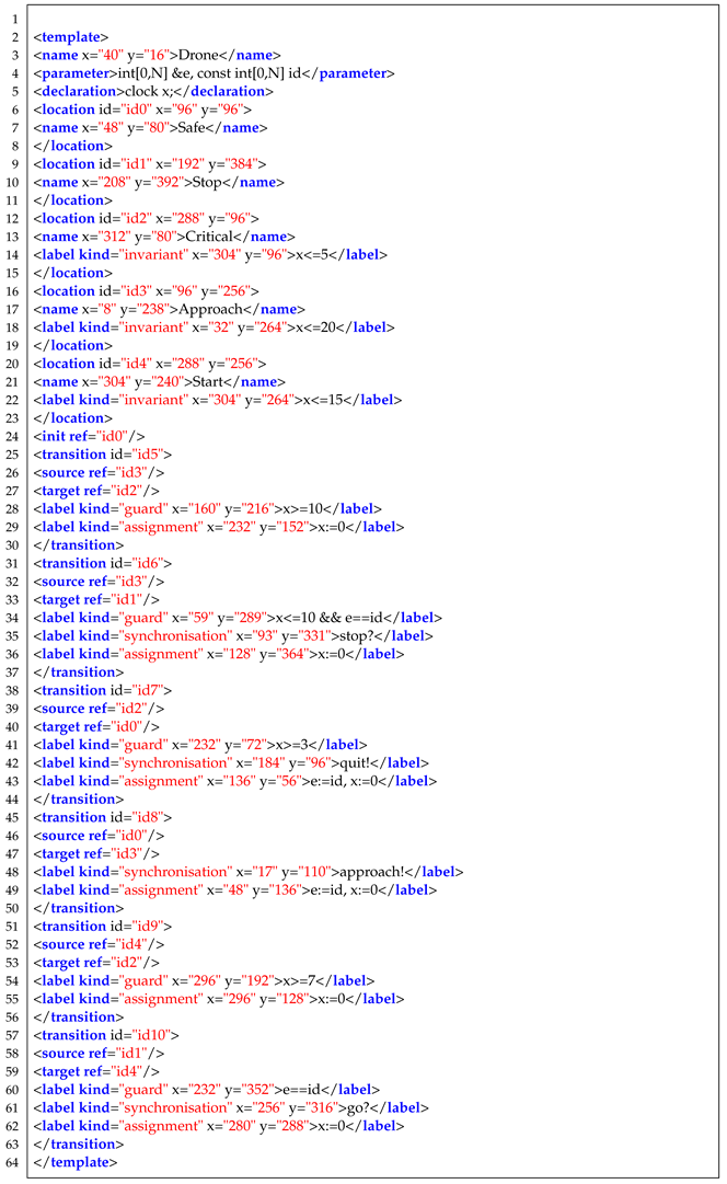 |
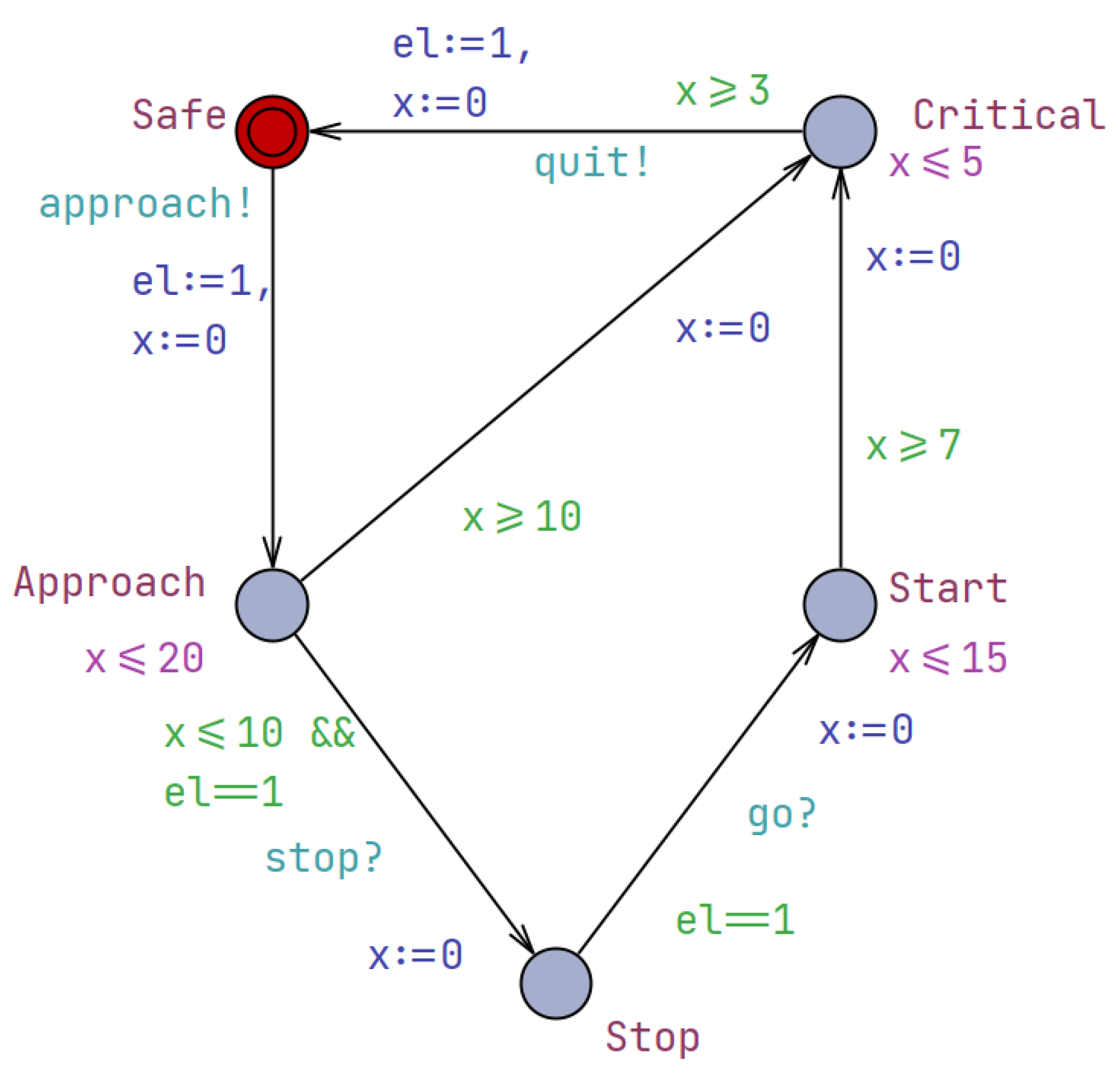
The drone’s behavior is described using locations, transitions, and labels. Locations denote the distinct states or positions that the drone can occupy, such as “Safe”, “Stop”, “Critical”, and “Start”. These locations represent the drone’s operational modes and reflect its current capabilities or constraints. The transitions between locations are labeled with guards, synchronizations, and actions. The guards specify the conditions that must be met for the transition to be taken, such as energy level thresholds or time constraints. The synchronizations indicate the communication and coordination with other components, like the controller or the queue. For example, the “approach?” and “stop!” synchronizations allow the drone to receive instructions from the controller. The actions, on the other hand, update the drone’s internal variables or perform specific tasks, such as adjusting the energy level or updating the position.
The UPPAAL timed automaton corresponding to this XML code is depicted in Figure 3, providing a visual representation of the drone’s behavior and the relationships between its different states. This model allows for the analysis and verification of the drone’s actions, ensuring that they adhere to the system’s requirements and constraints. Furthermore, the drone automata can be extended to incorporate more advanced features, such as adaptive battery management, collision avoidance, or task-specific capabilities. By enhancing the drone’s behavioral model, the system can better accommodate unexpected situations, optimize resource utilization, and improve the overall reliability and performance of the drone operations.
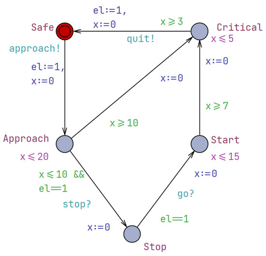
Figure 3.
The UPPAAL timed automaton depicting the behavior of a drone.
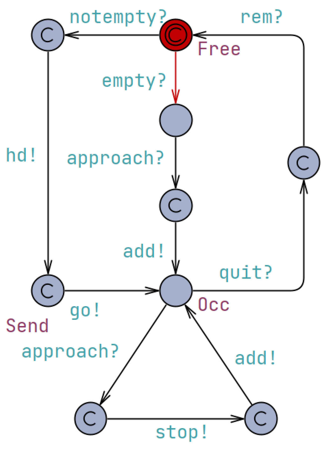
The controller, as modeled in Figure 4, serves as a central component responsible for managing and coordinating the actions of the system. It interacts with the drones and the queue to ensure proper synchronization and control. The controller automaton consists of several locations representing different states. The “Free” location indicates that the controller is available and not engaged in any specific task. The “Occ” location represents the controller’s occupation or engagement in a particular action. Additionally, the controller may have other locations, such as “Coordinating” or ”Monitoring”, which represent its involvement in specific coordination or monitoring tasks within the system. The transitions between locations are labeled with synchronization events denoting the communication and coordination with other components. For example, the “notempty?” and “empty?” synchronizations indicate the controller’s interaction with the queue, checking whether it is not empty or empty, respectively. These synchronizations allow the controller to be aware of the queue’s state and make decisions accordingly.
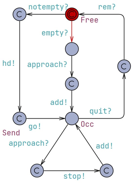
Figure 4.
The UPPAAL timed automaton depicting the behavior of the controller.
The controller also communicates with the drones through synchronizations such as “approach?” and “stop!” which coordinate the approach of a drone and command it to stop, respectively. These synchronizations ensure that the drones’ actions are aligned with the controller’s directives, enabling the system to function cohesively. The controller may also have additional synchronizations, such as “takeoff” or “land”, to coordinate the drones’ flight maneuvers and maintain overall system coordination. Furthermore, the controller may have internal transitions labeled with conditions or actions that reflect its decision-making process. For instance, there could be a transition from “Free” to “Occ” guarded by a condition like “queue.size() > 0”, indicating that the controller becomes occupied when the queue is not empty. These internal transitions and conditions allow the controller to respond to the system’s state and make appropriate decisions to maintain the overall system’s functionality.
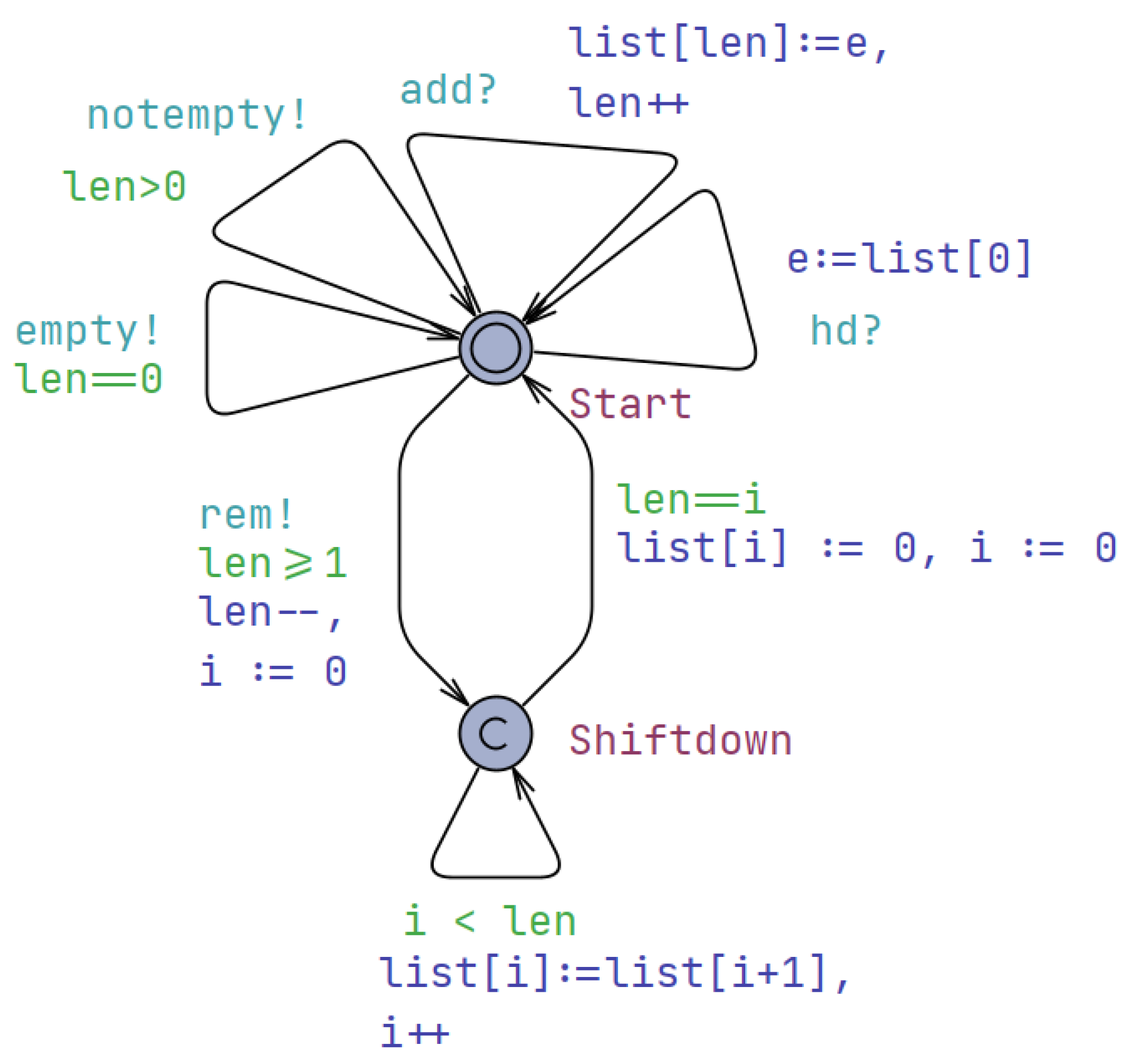
The queue automaton presented in Figure 5 consists of two locations: “Start” and “Shiftdown”. The “Start” location represents the initial state of the queue, while the “Shiftdown” location represents the process of shifting down elements in the list. The transitions between locations define the actions and conditions of the queue. They are labeled with guards, assignments, and synchronizations. The guards specify conditions that must be met for a transition to be taken. For example, the guard i < len ensures that the variable i is less than the current length of the list. The assignments update the values of variables. For instance, the assignment list[i] := list[i + 1], i++ shifts down elements in the list by assigning the value of list[i + 1] to list[i] and incrementing i by one. The synchronizations indicate the interaction and synchronization with other components. The “rem!” synchronization represents the removal of an element from the queue, “empty!” indicates that the queue is empty, “add?” represents the addition of an element to the queue, and “hd?” denotes a request to retrieve the first element from the queue. The automaton includes an initial state set to the “Start” location, indicating that it starts in an idle state.
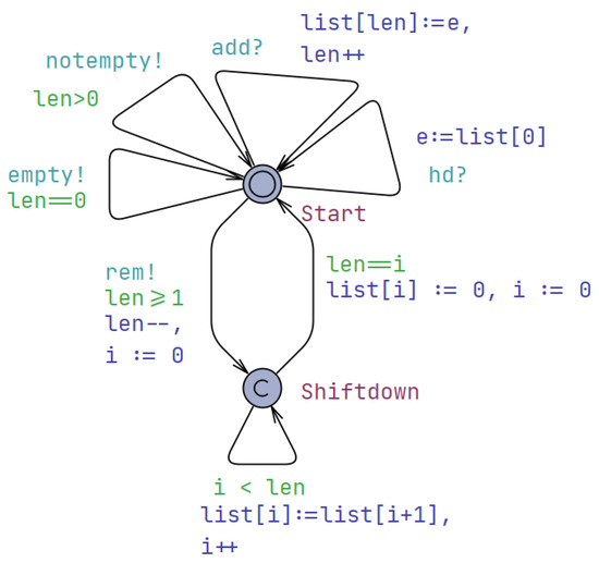
Figure 5.
The UPPAAL timed automaton depicting the behavior of the queue of drones.
The queue automaton also includes error-handling mechanisms to ensure the integrity and reliability of the system. For instance, there may be transitions labeled with guards like that handle cases where the index i exceeds the length of the list, preventing out-of-bounds access. Additionally, the queue may have a maximum capacity, and the automaton can include transitions to manage overflow situations, such as rejecting new additions or dropping the oldest elements to make room for new ones. Furthermore, the queue automaton can be enhanced with additional locations and transitions to support more complex queue operations, such as priority-based queueing, batch processing, or reordering of elements. These advanced features can enable the system to handle more sophisticated requirements and optimize the overall workflow.
The entire system comprises multiple interconnected automata that work together to achieve a coordinated and synchronized operation. It consists of six drone automata, one controller automaton, and one queue automaton. Each drone automaton represents an individual drone, while the controller automaton manages and coordinates the actions of the drones. The queue automaton is responsible for managing a list of tasks or commands for the drones. These automata synchronize their actions and communicate through shared actions and variables.
5. Simulation and Verification
5.1. Simulation
Simulation is a valuable tool for understanding and validating the behavior and performance of a system. In this subsection, we discuss the concept of simulation and its application in our case study. We also explore two important techniques: symbolic simulation and concrete simulation.
Symbolic simulation is a technique employed to analyze systems with large state spaces efficiently. In symbolic simulation, sets of states are represented symbolically, allowing for the exploration of various scenarios and the generation of traces to observe the system’s behavior. It abstracts away the precise timing details between consecutive events and focuses on the overall behavior of the system. Symbolic simulation is particularly useful when dealing with complex interactions and large-scale systems. In our case study, we utilized the symbolic simulator provided by UPPAAL to perform symbolic simulation of the drone fleet management system. By representing sets of states symbolically, we could explore different scenarios and analyze the behavior of the system. We specified temporal logic properties, such as safety and liveness properties. Symbolic simulation enabled us to gain insights into the system’s dynamics, identify potential design flaws, and refine the system’s architecture for improved reliability.
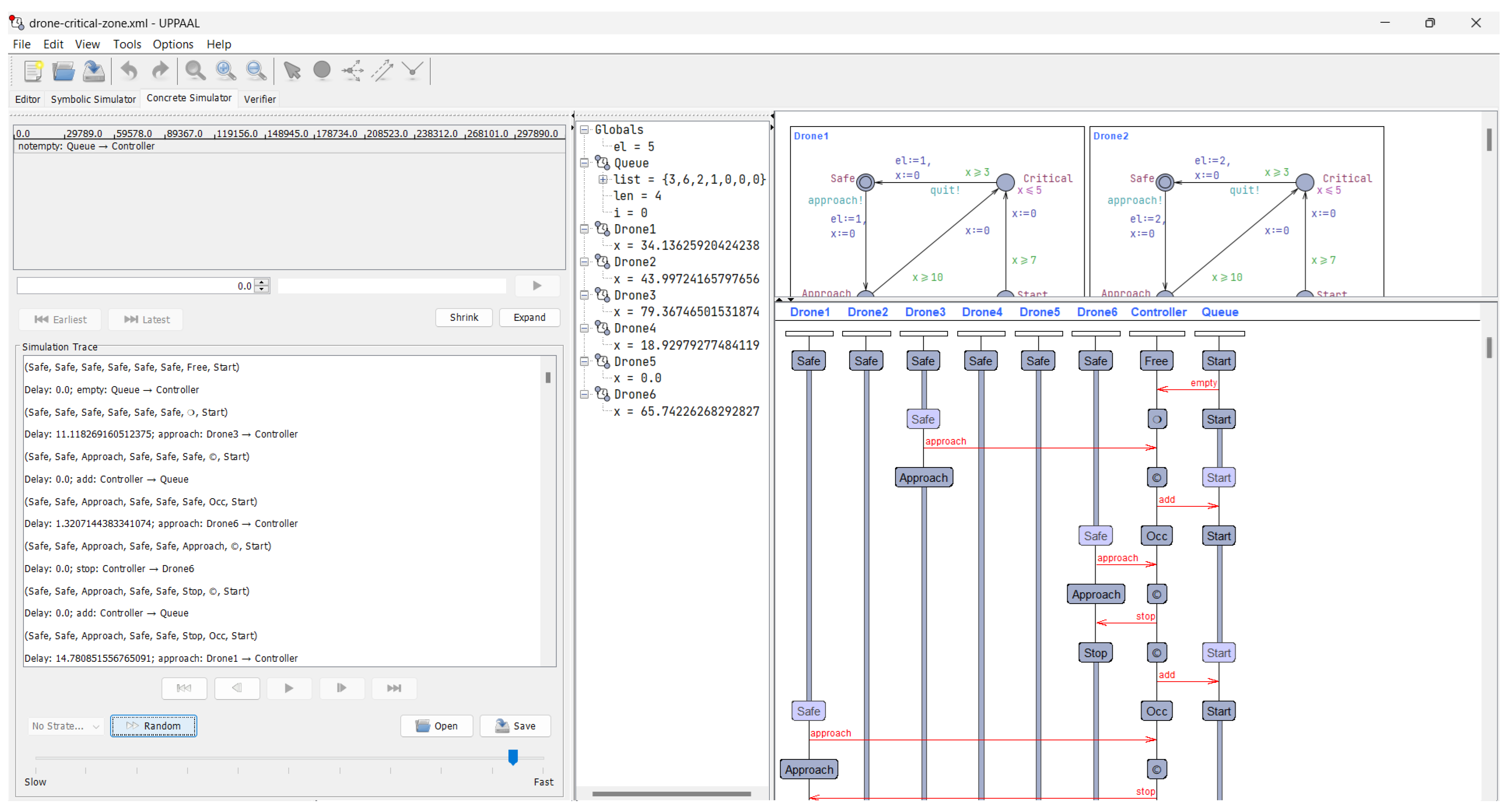
In contrast with symbolic simulation, concrete simulation considers precise and specific time values between consecutive events. It aims to capture the system’s behavior in real time and provides a detailed understanding of how the system operates under specific inputs and initial states. Concrete simulation allows for the observation of the system’s behavior at a fine-grained level, including the precise timing of events and the interactions between system components.
Symbolic simulation in our case study was performed using the timed automata modeling language supported by the UPPAAL tool. We specified the behavior of the various components of the drone fleet management system, such as the drones, the control center, and the communication infrastructure, as interconnected timed automata. These automata models captured the discrete state changes, timing constraints, and synchronization mechanisms governing the system’s operation.
To perform symbolic simulation, we first defined a set of temporal logic properties that we wanted to verify, such as safety conditions (e.g., no drone collisions) and liveness properties (e.g., reliable delivery of sensor data). UPPAAL’s symbolic model checker then explored the state space of the system model, representing sets of states symbolically using Difference Bound Matrices (DBMs). This allowed us to efficiently analyze a large number of possible scenarios and generate execution traces that demonstrated the system’s behavior with respect to the specified properties.
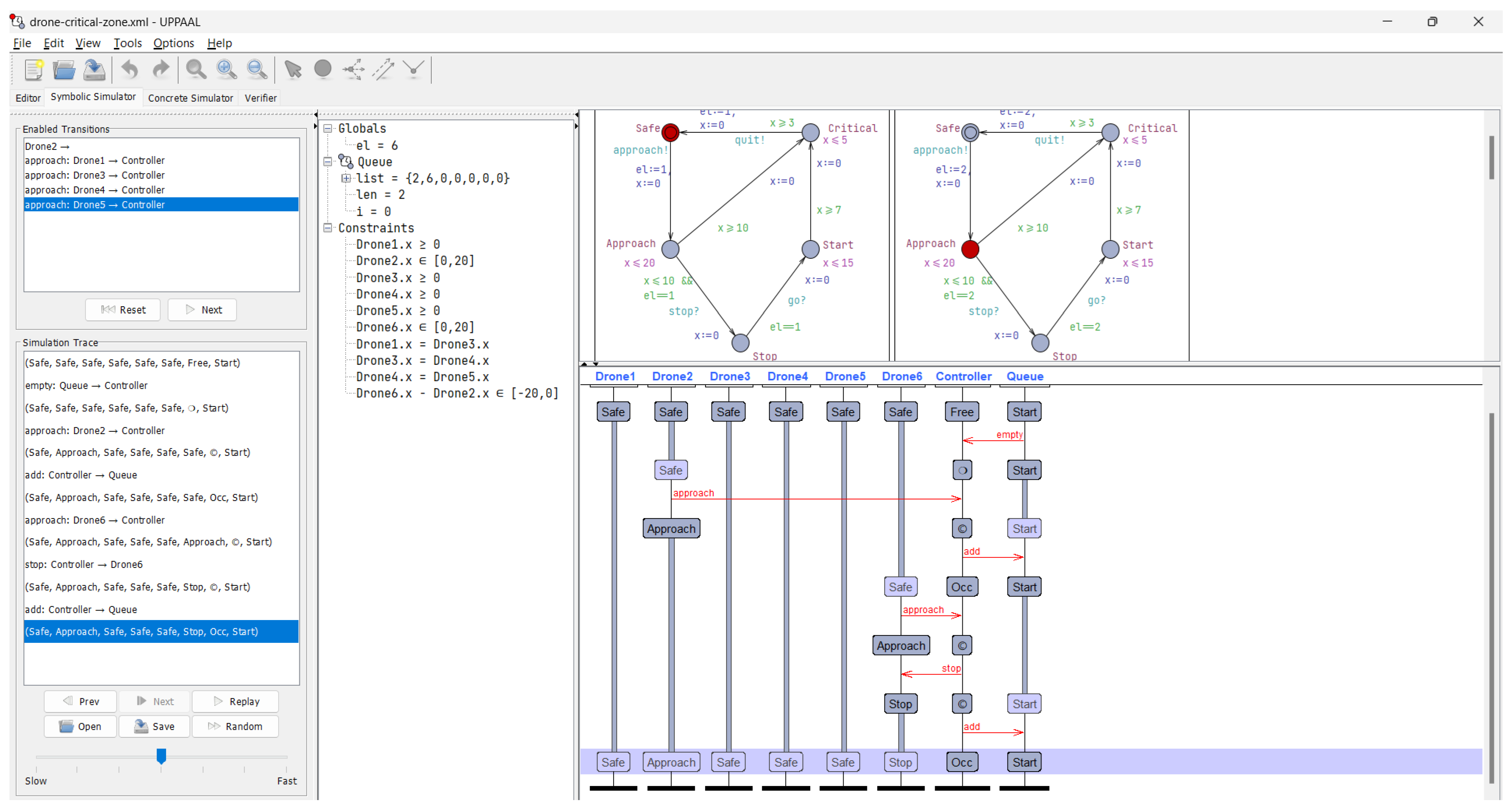
The symbolic simulation results provided us with valuable insights into the overall dynamics of the drone fleet management system. By observing the symbolic traces, we were able to identify potential design issues, such as deadlock conditions or violations of safety constraints. This informed our refinement of the system architecture and helped us optimize the coordination algorithms and resource allocation strategies employed by the control center. Figure 6 and Figure 7 show screenshots of symbolic and concrete simulations, respectively.
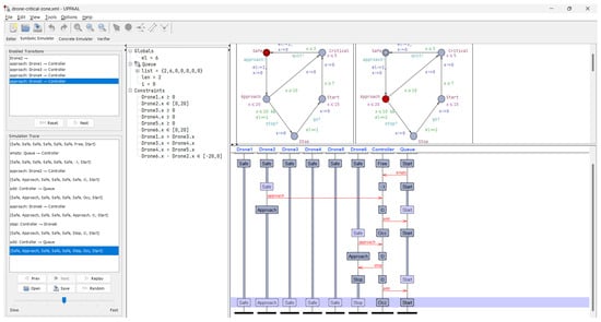
Figure 6.
Screenshot of the symbolic simulation.
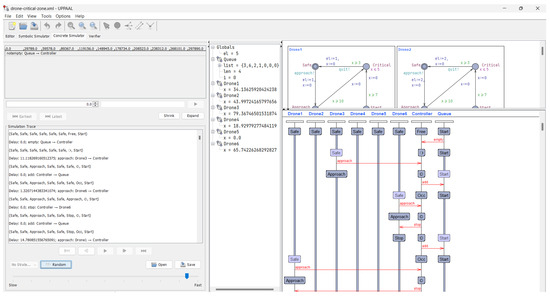
Figure 7.
Screenshot of the concrete simulation.
It is important to note that while simulation is a powerful technique, it has its limitations. Simulation provides valuable insights into the system’s behavior and performance, but it does not guarantee the correctness of the system with 100% certainty. Other formal verification techniques and real-world testing are necessary to complement the simulation results and ensure the system’s reliability and safety.
5.2. Verification
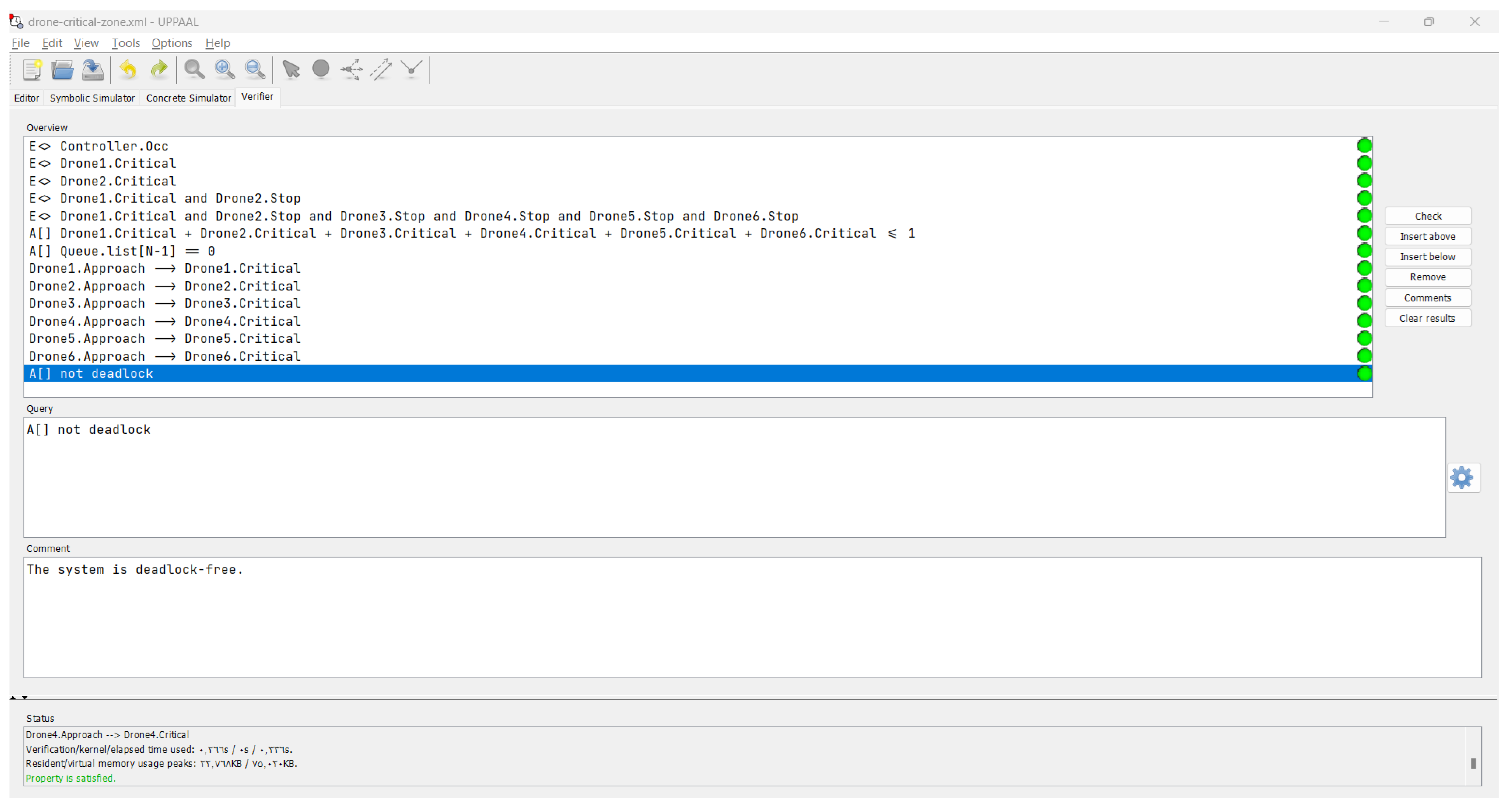
In this section, we present the results of the verification process for the drone system using the UPPAAL model checker. We have checked a set of properties to ensure the correctness and desired behavior of the system. Table 2 provides an overview of the properties considered in the verification process, along with their corresponding formulas and explanations. All the properties listed in Table 2 have been checked and verified to ensure the correctness and desired behavior of the drone system. The UPPAAL model checker was used to analyze the system and provide results for each property. Figure 8 displays the results of the verification process. Below, we provide an explanation for each property.
Table 2.
Verification properties.
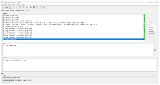
Figure 8.
Verification results: all properties are correct as indicated by the green disks.
- Property 1: This property ensures that the controller has received and stored messages from approaching drones in the queue. The formula Controller.Occ states that there exists a future state where the controller’s occupancy property is true.
- Property 2: This property verifies that Drone 1 enters the critical zone when it is in a critical state. The formula Drone1.Critical states that there exists a future state where Drone 1 is in a critical state.
- Property 3: Similar to Property 2, this property ensures that Drone 2 enters the critical zone when it is in a critical state. The formula Drone2.Critical states that there exists a future state where Drone 2 is in a critical state.
- Property 4: This property guarantees that Drone 1 enters the critical zone and Drone 2 stops when Drone 1 is in a critical state. The formula Drone1.Critical ∧ Drone2.Stop states that there exists a future state where Drone 1 is in a critical state and Drone 2 has stopped.
- Property 5: Similar to Property 4, this property verifies that all drones (Drone 1 to Drone 6) have entered the critical zone and stopped when Drone 1 is in a critical state. The formula Drone1.Critical ∧ Drone2.Stop ∧ Drone3.Stop ∧ Drone4.Stop ∧ Drone5.Stop ∧ Drone6.Stop states that there exists a future state where all drones have stopped and Drone 1 is in a critical state.
- Property 6: This safety property ensures that, at most, one drone is present in the critical zone at any given time. The formula Drone1.Critical + Drone2.Critical + Drone3.Critical + Drone4.Critical + Drone5.Critical + Drone6.Critical <= 1 states that, for all states, the sum of the crossing flags of all drones in the critical zone is less than or equal to 1.
- Property 7: This safety property verifies that the last element in the queue is always zero, indicating an empty queue. The formula Queue.list[N-1] == 0 states that, for all states, the last element of the queue is equal to zero.
- Properties 8–13: These liveness properties ensure that when a drone is approaching the critical zone, it eventually enters the critical zone. For example, Property 8 states that if Drone 1 is approaching (Drone1.Approach), it will eventually enter the critical zone (Drone1.Critical). Similar properties are defined for Drone 2 to Drone 6.
- Property 14: This property guarantees that the system does not reach a deadlock state. The formula not deadlock states that, for all states, it is not possible to reach a deadlock state.
The verification process plays a crucial role in ensuring the correctness and reliability of the drone system. By checking a comprehensive set of properties, the team can identify and address potential issues early in the development cycle. The use of the UPPAAL model checker provides a powerful and formal verification approach, allowing for the systematic analysis of the system’s behavior and the validation of its desired properties. One of the key benefits of the verification process is its ability to uncover subtle errors or edge cases that might not be easily detected through testing alone. By exploring the system’s state space and verifying specific behavioral constraints, the verification process can help detect and resolve potential safety and liveness violations, ensuring that the drone system operates as intended under various conditions. The verification process also provides a means to validate the system’s adherence to critical safety and ethical guidelines. By defining properties that capture the desired ethical and safety-related behaviors, the team can ensure that the drone system operates in a manner that respects human life and minimizes potential harm. Furthermore, the verification results provide valuable insights into the system’s behavior, allowing the development team to refine the design and implementation as necessary. The clear presentation of the verification properties and their corresponding formulas, along with the graphical representation of the results, facilitates the understanding and communication of the verification process, enabling stakeholders to have confidence in the system’s correctness. The verification process successfully checked and validated all the properties, ensuring that the drone system meets the desired specifications and operates correctly. The successful verification of the drone system’s properties not only builds confidence in its technical correctness but also demonstrates the team’s commitment to responsible and ethical development. This comprehensive approach to verification serves as a testament to the drone system’s reliability and the development team’s dedication to delivering a safe and trustworthy solution.
6. Limitations of Timed Automata Modeling
While timed automata provide a powerful formal foundation for modeling and analyzing real-time systems, it is important to acknowledge that they have certain limitations and cannot capture every aspect of a complex system. The use of timed automata for modeling a drone control system is primarily focused on the logical decision-making subsystem, and may not be able to capture the full dynamics and environmental factors that influence the behavior of the drone.
For instance, the timed automata model may not be able to accurately represent the influence of navigation errors, meteorological conditions, enemy counteraction, or noise in control signals. These aspects of the drone system’s behavior are more closely tied to the physical dynamics and environmental interactions, which may require different modeling formalisms to capture accurately.
It is important to note that there is no single modeling language or formalism that can handle all aspects of a complex system. Depending on the specific goals and requirements of the analysis, different modeling approaches may be more suitable. For example, the drone system dynamics and kinematics could be better captured using mathematical models of controlled bodies, while the decision-making subsystem may be more appropriately modeled using timed automata.
In the future, as the complexity of real-time systems increases, it may become necessary to combine multiple modeling languages and formalisms to provide a comprehensive representation of the system. This could involve integrating timed automata with other modeling techniques, such as differential equations, stochastic processes, or hybrid automata, to capture the various aspects of the system’s behavior. By utilizing a combination of modeling approaches, researchers and engineers can gain a more complete understanding of the system and its properties, leading to more reliable and robust real-time systems.
Addressing the scalability challenges of using timed automata for verifying larger drone systems or more complex scenarios is an important consideration. As the number of drones or the complexity of the system increases, the state space explored by the UPPAAL model checker can grow exponentially, potentially leading to performance and memory issues. To mitigate these scalability concerns, we plan to investigate techniques such as abstraction, compositional verification, and modular modeling. Abstraction methods can be used to create simplified models that capture the essential behavior of the system, while still preserving the relevant properties for verification. Compositional verification approaches would allow us to break down the system into smaller, more manageable components, verifying each component independently and then combining the results. Additionally, adopting a modular modeling approach, where individual drones or subsystems are modeled as separate units, can help manage the complexity and improve the scalability of the verification process. By employing these strategies, we aim to maintain the rigor and reliability of the timed automata-based verification while ensuring that the approach remains feasible and efficient even for larger-scale drone systems and more complex operational scenarios.
To make the use of timed automata more accessible to practitioners, we have leveraged an existing graphical modeling environment that allows users to specify the system’s behavior using familiar notations, without requiring in-depth knowledge of the underlying formalism. This graphical interface, integrated with the UPPAAL model checker, enables the seamless transition from modeling to formal verification. The models created in the graphical environment are automatically translated into the input format required by UPPAAL, streamlining the process and hiding the technical details of timed automata. Additionally, we have focused on improving the presentation of verification results, providing clear visualizations and reports that highlight the key properties and their fulfillment status. By building upon an existing graphical modeling tool and enhancing the user experience, we aim to lower the entry barrier and enable domain experts to actively participate in the validation of their systems, even without a strong background in formal methods.
7. Discussion
During the course of this research, we encountered several challenges that are worth noting. First, the complexity of the drone system, with multiple interacting components and intricate coordination requirements, posed challenges in modeling and verification. Ensuring the completeness and accuracy of the model, as well as formulating appropriate properties for verification, required careful attention and expertise. Additionally, the scalability of the verification process became a concern as the system size increased. Addressing these challenges required a combination of theoretical knowledge, modeling expertise, and optimization techniques. One of the major challenges identified is the difficulty of increasing the number of drones in the system. As the number of drones grows, the coordination and management of their activities become more intricate, requiring careful consideration of communication protocols, collision avoidance, and resource allocation. This challenge becomes particularly pronounced when scaling up to a large number of drones. To address this challenge, one possible approach is to explore decentralized control strategies, where decision making is distributed among individual drones. This can help alleviate the computational burden on the central controller and improve the scalability of the system. Additionally, leveraging swarm intelligence techniques, inspired by collective behavior in natural systems, can enable effective coordination and emergent behaviors in large groups of autonomous drones.
Integrating the formal timed automata-based model with physical modeling approaches is an important consideration to account for the environmental and physical dynamics that can impact the drone system’s behavior. We plan to explore the use of co-simulation techniques, where the formal model is coupled with a physics-based simulation engine that can accurately represent the drone’s aerodynamics, sensor interactions with the environment, and other physical phenomena. By linking the logical model of the drone’s decision making and control algorithms with a detailed physical simulation, we can capture the complex interactions between the drone’s software components and the real-world dynamics. This integrated approach will allow us to validate the system’s performance not only against the formal properties but also under realistic environmental conditions, such as wind gusts, terrain variations, and sensor failures. The results from the co-simulation can then be used to refine the formal model, ensuring that it accurately reflects the physical constraints and limitations of the drone system. This combination of formal verification and physical modeling will provide a comprehensive assessment of the drone’s overall behavior and resilience, strengthening the confidence in the system’s correctness and reliability.
Computational efficiency is a key concern in our use of timed automata for system validation and verification. The analysis of timed automata models can be computationally intensive, especially for complex systems with large state spaces. To address this challenge, we have explored several optimization strategies to improve the scalability and performance of our simulations. One key optimization involves leveraging the modular structure of the timed automata models. By decomposing the system into smaller, more manageable components, we can take advantage of compositional verification techniques, which can significantly reduce the overall computational burden. This modular approach allows us to analyze the individual components separately and then combine the results, rather than having to explore the entire state space at once. Additionally, we have investigated the use of abstraction and approximation techniques to further improve the computational efficiency. By identifying and exploiting the appropriate levels of abstraction for different aspects of the system, we can trade off precision for computational efficiency, without compromising the overall correctness of the analysis. This could involve, for example, using more coarse-grained models for certain system components or applying symbolic model checking methods that can leverage efficient data structures and algorithms. Furthermore, we have explored the parallelization of our simulation and verification processes, leveraging the computational power of modern hardware architectures. By distributing the workload across multiple cores or machines, we can achieve significant speedups, allowing us to handle larger and more complex models within reasonable time frames. While the computational challenges of timed automata analysis remain, these optimization strategies, along with continued advancements in hardware and software technologies, have enabled us to make significant progress in improving the scalability and practicality of our formal verification approach. We are committed to ongoing research and development in this area to further enhance the computational efficiency of our simulations and validations.
While we have not yet conducted real-world validation of our proposed strategy, the use of formal methods, such as timed automata, has proven invaluable in the preliminary design and model validation stages. Timed automata have allowed us to rigorously specify the system’s behavior and formally verify key properties, such as safety and timing constraints, prior to any physical implementation. This approach has helped us identify potential issues and refine the system design early on, reducing the risk of costly errors or failures in the later stages of development. By leveraging the power of formal verification, we have been able to build confidence in the correctness and reliability of our drone system’s theoretical foundations, laying the groundwork for future real-world validation and deployment. While real-world testing is a crucial next step, the insights gained from the formal methods-based analysis have been instrumental in preparing the system for these real-world challenges and ensuring a robust and well-designed foundation.
8. Conclusions and Future Work
In this paper, we have presented a comprehensive study on the design and verification of a drone system for critical zone monitoring. The objective of the system is to ensure the safe and efficient operation of drones within a designated critical zone. We have developed a formal model using the UPPAAL tool and conducted a thorough verification process to validate the system’s correctness and desired behavior. The contribution of this paper lies in several key aspects. First, we have proposed a novel architecture for the drone system, incorporating a controller, multiple drones, and a critical zone. The system’s design enables effective coordination and monitoring of drone activities, ensuring the timely detection and handling of critical situations. Second, we have employed formal modeling and verification techniques, specifically utilizing the UPPAAL model checker, to rigorously analyze the system’s properties and ensure its correctness. Through this process, we have successfully validated a set of properties, including safety, liveness, and deadlock freedom, demonstrating the system’s reliability and adherence to the specified requirements.
Looking ahead, there are several potential avenues for future research and development. First, the integration of machine learning and artificial intelligence techniques can enhance the system’s capabilities, enabling more intelligent decision making and adaptive behavior. Incorporating learning algorithms for drone navigation, obstacle detection, and critical situation handling can lead to improved performance and responsiveness. Second, the deployment of advanced sensing and communication technologies, such as computer vision, LiDAR, and 5G networks, can further enhance the system’s situational awareness and communication capabilities. Leveraging these technologies can enable more precise monitoring, faster data transmission, and improved coordination among the drones. Lastly, conducting real-world experiments and validations of the system can provide valuable insights and feedback, allowing for refinement and optimization based on practical scenarios and constraints.
Funding
This research received no external funding.
Data Availability Statement
Data is contained within the article.
Conflicts of Interest
The author declares no conflict of interest.
References
- Boccadoro, P.; Striccoli, D.; Grieco, L.A. An extensive survey on the Internet of Drones. Ad. Hoc. Netw. 2021, 122, 102600. [Google Scholar] [CrossRef]
- Jiménez López, J.; Mulero-Pázmány, M. Drones for conservation in protected areas: Present and future. Drones 2019, 3, 10. [Google Scholar] [CrossRef]
- Krichen, M. A survey on formal verification and validation techniques for internet of things. Appl. Sci. 2023, 13, 8122. [Google Scholar] [CrossRef]
- Mendoza-Mendoza, J.A.; Gonzalez-Villela, V.J.; Aguilar-Ibañez, C.F.; Fonseca-Ruiz, L.; Mendoza-Mendoza, J.A.; Gonzalez-Villela, V.J.; Aguilar-Ibañez, C.F.; Fonseca-Ruiz, L. Control of drones. In Drones to Go: A Crash Course for Scientists and Makers; Springer: Berlin/Heidelberg, Germany, 2021; pp. 87–162. [Google Scholar]
- Kangunde, V.; Jamisola, R.S., Jr.; Theophilus, E.K. A review on drones controlled in real-time. Int. J. Dyn. Control 2021, 9, 1832–1846. [Google Scholar] [CrossRef] [PubMed]
- Alur, R.; Dill, D. Automata for modeling real-time systems. In Proceedings of the Automata, Languages and Programming: 17th International Colloquium, Warwick, UK, 16–20 July 1990; Springer: Berlin/Heidelberg, Germany, 1990; pp. 322–335. [Google Scholar]
- Quottrup, M.M.; Bak, T.; Zamanabadi, R. Multi-robot planning: A timed automata approach. In Proceedings of the IEEE International Conference on Robotics and Automation, ICRA’04. 2004, IEEE, New Orleans, LA, USA, 26 April–1 May 2004; Volume 5, pp. 4417–4422. [Google Scholar]
- Bengtsson, J.; Yi, W. Timed automata: Semantics, algorithms and tools. In Advanced Course on Petri Nets; Springer: Berlin/Heidelberg, Germany, 2003; pp. 87–124. [Google Scholar]
- Kaynar, D.K. The Theory of Timed I/O Automata; Morgan & Claypool Publishers: San Rafael, CA, USA, 2011; Volume 5. [Google Scholar]
- Yovine, S. Model checking timed automata. In School Organized by the European Educational Forum; Springer: Berlin/Heidelberg, Germany, 1996; pp. 114–152. [Google Scholar]
- Li, Y.; Liu, J. Formal Methods for Control of Nonlinear Systems; Chapman and Hall/CRC: Boca Raton, FL, USA, 2022. [Google Scholar]
- Ramaswamy, A.; Monsuez, B.; Tapus, A. Formal Specification of Robotic Architectures for Experimental Robotics. In Metrics of Sensory Motor Coordination and Integration in Robots and Animals: How to Measure the Success of Bioinspired Solutions with Respect to their Natural Models, and Against More ‘Artificial’Solutions? Springer: Berlin/Heidelberg, Germany, 2020; pp. 15–37. [Google Scholar]
- Yin, X.; Li, S. Recent advances on formal methods for safety and security of cyber-physical systems. Control. Theory Technol. 2020, 18, 459–461. [Google Scholar] [CrossRef]
- Tehseen, A.; Zafar, N.A.; Ali, T.; Jameel, F.; Alkhammash, E.H. Formal modeling of iot and drone-based forest fire detection and counteraction system. Electronics 2021, 11, 128. [Google Scholar] [CrossRef]
- Gu, R.; Enoiu, E.; Seceleanu, C. TAMAA: UPPAAL-based mission planning for autonomous agents. In Proceedings of the 35th Annual ACM Symposium on Applied Computing, Brno, Czech Republic, 30 March–3 April 2020; pp. 1624–1633. [Google Scholar]
- Vogel, T.; Carwehl, M.; Rodrigues, G.N.; Grunske, L. A property specification pattern catalog for real-time system verification with UPPAAL. Inf. Softw. Technol. 2023, 154, 107100. [Google Scholar] [CrossRef]
- Lehmann, S.; Schupp, S. Bounded DBM-based clock state construction for timed automata in Uppaal. Int. J. Softw. Tools Technol. Transf. 2023, 25, 19–47. [Google Scholar] [CrossRef]
- Shokri-Manninen, F.; Tsiopoulos, L.; Vain, J.; Waldén, M. Integration of iUML-B and UPPAAL timed automata for development of real-time systems with concurrent processes. In Proceedings of the Rigorous State-Based Methods: 7th International Conference, ABZ 2020, Proceedings 7, Ulm, Germany, 27–29 May 2020; Springer: Berlin/Heidelberg, Germany, 2020; pp. 186–202. [Google Scholar]
- Jeyaraman, S.; Tsourdos, A.; Zbikowski, R.; White, B. Formal techniques for the modelling and validation of a co-operating UAV team that uses Dubins set for path planning. In Proceedings of the American Control Conference, Portland, OR, USA, 8–10 June 2005; Volume 7, pp. 4690–4695. [Google Scholar] [CrossRef]
- Abed, S.; Rashid, A.; Hasan, O. Formal analysis of unmanned aerial vehicles using higher-order-logic theorem proving. J. Aerosp. Inf. Syst. 2020, 17, 481–495. [Google Scholar] [CrossRef]
- Huang, Y.; Wang, N.; Li, J. A task planning method for multi-UAV from local LTL specifications. In Proceedings of the 2021 IEEE International Conference on Unmanned Systems (ICUS), Beijing, China, 15–17 October 2021; pp. 618–623. [Google Scholar] [CrossRef]
- Bernardeschi, C.; Domenici, A.; Fagiolini, A.; Palmieri, M. Co-simulation and formal verification of co-operative drone control with logic-based specifications. Comput. J. 2023, 66, 295–317. [Google Scholar] [CrossRef]
- Rashid, A.; Hasan, O.; Abed, S. Using an Interactive Theorem Prover for Formally Analyzing the Dynamics of the Unmanned Aerial Vehicles. In Mobile Robot: Motion Control and Path Planning; Springer: Berlin/Heidelberg, Germany, 2023; pp. 253–282. [Google Scholar]
- Ju, C.; Son, H.I. Discrete Event Systems based Modeling for Agricultural Multiple Unmanned Aerial Vehicles: Automata Theory Approach. In Proceedings of the 2018 18th International Conference on Control, Automation and Systems (ICCAS), PyeongChang, Republic of Korea, 17–20 October 2018; pp. 258–260. [Google Scholar]
- Doherty, P.; Kvarnström, J.; Heintz, F. A temporal logic-based planning and execution monitoring framework for unmanned aircraft systems. Auton. Agents-Multi-Agent Syst. 2009, 19, 332–377. [Google Scholar] [CrossRef]
- Costa, I.C.; de Oliveira, J.M.P. Modeling Unmanned Aircraft System conflicts resolution based on a real-time services approach. In Proceedings of the 2012 IEEE/AIAA 31st Digital Avionics Systems Conference (DASC), Williamsburg, VA, USA, 14–18 October 2012; pp. 8A5-1–8A5-8. [Google Scholar] [CrossRef]
- Ramos, D.B.; e Silva, R.A.B.; Costa, I.C.; Colonese, E.M.; de Oliveira, J.M.P. Modeling conflicts resolution of Unmanned Aircraft System using a lightweight Duration Calculus. In Proceedings of the 2011 IEEE/AIAA 30th Digital Avionics Systems Conference, Williamsburg, VA, USA, 14–18 October 2011; pp. 5A6-1–5A6-9. [Google Scholar] [CrossRef]
- Humphrey, L.R. Model checking for verification in UAV cooperative control applications. In Recent Advances in Research on Unmanned Aerial Vehicles; Springer: Warsaw, Poland, 2013; pp. 69–117. [Google Scholar]
- Kügler, M.E.; Rhein, J.; Holzapfel, F. Validation of decision logic of an autoland system for a UAV using model-based safety-assessment techniques. Ceas Aeronaut. J. 2020, 11, 93–110. [Google Scholar] [CrossRef]
- Schiøler, H.; Totu, L.; Dimon, J.; Larsen, K.G.; Taankvist, J.H. Time Optimal Robust Fleet Management of Micro UAV through Timed Games Formulation. In Proceedings of the 2018 IEEE Conference on Control Technology and Applications (CCTA), Copenhagen, Denmark, 21–24 August 2018; pp. 146–152. [Google Scholar] [CrossRef]
Disclaimer/Publisher’s Note: The statements, opinions and data contained in all publications are solely those of the individual author(s) and contributor(s) and not of MDPI and/or the editor(s). MDPI and/or the editor(s) disclaim responsibility for any injury to people or property resulting from any ideas, methods, instructions or products referred to in the content. |
© 2024 by the author. Licensee MDPI, Basel, Switzerland. This article is an open access article distributed under the terms and conditions of the Creative Commons Attribution (CC BY) license (https://creativecommons.org/licenses/by/4.0/).