Review

Unveiling the Sub-10 GHz Performance of SMA Connectors: A Comparative Analysis

Department of Computer Science and Communications Technologies, Vilnius Gediminas Technical University (VILNIUS TECH), 10105 Vilnius, Lithuania
*
Author to whom correspondence should be addressed.
Electronics 2024, 13(14), 2686; https://doi.org/10.3390/electronics13142686
Submission received: 21 May 2024 / Revised: 4 July 2024 / Accepted: 8 July 2024 / Published: 9 July 2024
(This article belongs to the Special Issue Feature Review Papers in Microelectronics)

Abstract

:
This research review article provides a detailed examination of SMA (SubMiniature version A) connectors, which are integral components in high-frequency electronic systems. Through extensive S-parameter and time-domain reflectometry (TDR) measurements conducted on various SMA connector constructions, this study aims to evaluate the performance and impact of SMA connectors on signal integrity. Results reveal insights into the comparative performance of different SMA connector types mounted on PCB land pads, highlighting their strengths and limitations. Additionally, this paper explores the application of reference plane cut-outs for discontinuity impedance compensation, aiming to enhance the frequency response of SMA connectors. By linking measured performance parameters with relative market prices, this study offers valuable insights into the economic viability of different SMA connector types. The best and worst performing SMA connector measurements reveal an S11 < −10 dB bandwidth of more than 8 GHz and 1.5 GHz and a transition impedance of 46.5 Ω and 21 Ω, respectively. Overall, this research contributes to advancing the understanding and selection of SMA connectors for RF applications in telecommunications, aerospace, medical devices, and beyond.

1. Introduction

In today’s technological landscape, electronic development is rapidly focusing on high-frequency wireless electronics, driven by emerging technologies such as IoT, IoV, and Industry 4.0 [1,2]. This shift is accelerated by the widespread adoption of 5G technology, acting as a catalyst for faster and more reliable communication. Within high-frequency electronics, RF connectors, particularly SMA (SubMiniature version A) connectors, play a pivotal role in facilitating connectivity between distinct high-frequency planes. Widely used for robust connections, RF connectors are crucial in ensuring seamless communication within intricate electronic systems. With applications in measurements and testing, RF connectors serve as essential components, providing a reliable interface for precise analysis of high-frequency signals. SMA connectors, recognized for their high-frequency capabilities, are instrumental in achieving signal integrity in modern electronics. Their compact size and precision engineering make them the connector of choice in applications prioritizing miniaturization, including telecommunications, aerospace, and medical devices. Versatile across industries, SMA connectors offer flexibility in wireless communication systems, radar installations, and test and measurement equipment, contributing to their popularity. Commonly employed in laboratory and test environments, SMA connectors are preferred for accurate measurement and analysis of high-frequency signals. Their stable performance and ease of use make them indispensable for connecting instruments like spectrum analyzers, oscilloscopes, and network analyzers, facilitating precise testing and characterization of electronic components.
At present, there are numerous manufacturers of SMA connectors in the market, producing connectors of various designs from diverse materials. In the context of this research review paper, we present the results of S-parameter and time-domain reflectometry (TDR) measurements and investigations. The objective of this study was to evaluate the extensive range of connector constructions offered by one of the leading SMA connector manufacturers. Specifically, we aimed to verify the performance of each SMA connector-to-transmission line transition and assess their impact on signal integrity. The findings of this study contribute to the understanding of SMA connector characteristics, providing valuable insights into their functionality within high-frequency electronic systems.

1.1. Similar Works

SMA connectors are one of the most popular connectors in modern high-speed and RF equipment, and research papers have received a lot of attention from scientific researchers throughout the years. Mathematical models for SMA connectors have been proposed in [3,4], which resulted in S-parameter models and lumped component schematics. Papers in [5,6] focused on bandwidth improvement and return path analysis for board edge end-launch SMA connectors. Discontinuities in the transition from the SMA connector to the PCB greatly limit the performance. Equations estimating the edge-mount connector bandwidth were presented and confirmed. A wideband SMA-to-ESIW (empty substrate integrated waveguide) has been presented in [7], exhibiting an insertion loss of the back-to-back transition below 1 dB in a frequency range over 7 GHz. SMA-to-PCB transition optimization was conducted in [8], where an impedance compensation cut-out was proposed, in order to increase the bandwidth. Four vertical SMA connectors via optimization steps are listed in [9] in order to improve the signal transfer from the connector to the microstrip, including managing the influence of the signal pin antipad in a through-hole connector on the junction impedance. The paper in [10] explores adding a matching network at the input of the SMA connector in order to improve the S-parameter. The closest reference to this paper is the study in [11], where the authors present a performance comparison between through-hole vertical, end-launch, surface mount device (SMD) vertical, and solderless SMA connectors connected by microstrips and coplanar waveguides. Although the authors highlight solderless end-launch connectors as providing the best performance, they did not compare the results with all available types of connectors, nor did they analyze their respective connector-to-microstrip transition impedance TDR responses.

1.2. Motivation and Relevance

Modern electronics equipment utilizes excellent electrical performance from DC to higher than 20 GHz and outstanding mechanical durability. While they are most often associated with their use in the radio frequency (RF) industry, SMA connectors have a wide range of applications across various fields, including aerospace, telecommunications, medical equipment, and more. The latter connectors are built in accordance with MIL-C-39012 and CECC 22110/111 standards [12], allowing for easy interchangeability with other SMA connectors from different manufacturers. Moreover, nowadays SMA connectors are available in multiple configurations to suit different application requirements. These include straight connectors, right-angle connectors, bulkhead connectors, PCB-mount connectors, and adapters [13,14,15].
A set-up with various types of SMA connectors in a laser equipment front-end is presented in Figure 1. The latter example includes different filters, amplifiers, limiters, and power splitters in the form of separate PCBs and as modules (highlighted as numbers 1–6), all of which utilize the SMA connector. This set-up shows that modern systems can have one or more types of SMA connectors and in multiple quantities; thus, the transition from SMA to microstrip can affect the performance of the whole system. Considering the abundance of existing SMA connector types and the variation in their prices, designers must be aware of the limitations of connector performance depending on the type and cost.
This paper contributes to the existing literature in the field of high-frequency connector research. It proposes a practical review presented as a comparative qualitative analysis of the most popular types of SMA connectors mounted on PCB land pads, which are defined by the manufacturer and measured under the same working conditions. This paper considers the addition of reference plane cut-outs for discontinuity impedance compensation to see the scope of improvement and compare it with the best-in-class SMA connectors. Moreover, this paper links the measured SMA connector performance parameters with their relative market price, revealing which one(s) are the most economically viable.
The structure of this paper is as follows: The Introduction is a review of similar papers by other researchers and the motivation, followed by Section 2, which describes the measurement set-up and equipment. Section 3 outlines measurement results, comparing various types of SMA connectors mounted on microstrip transmission lines. The conclusion is provided in Section 4, summarizing the findings and implications of this study. This structured approach aims to offer a comprehensive exploration of the research while contributing to the existing body of knowledge in the field.

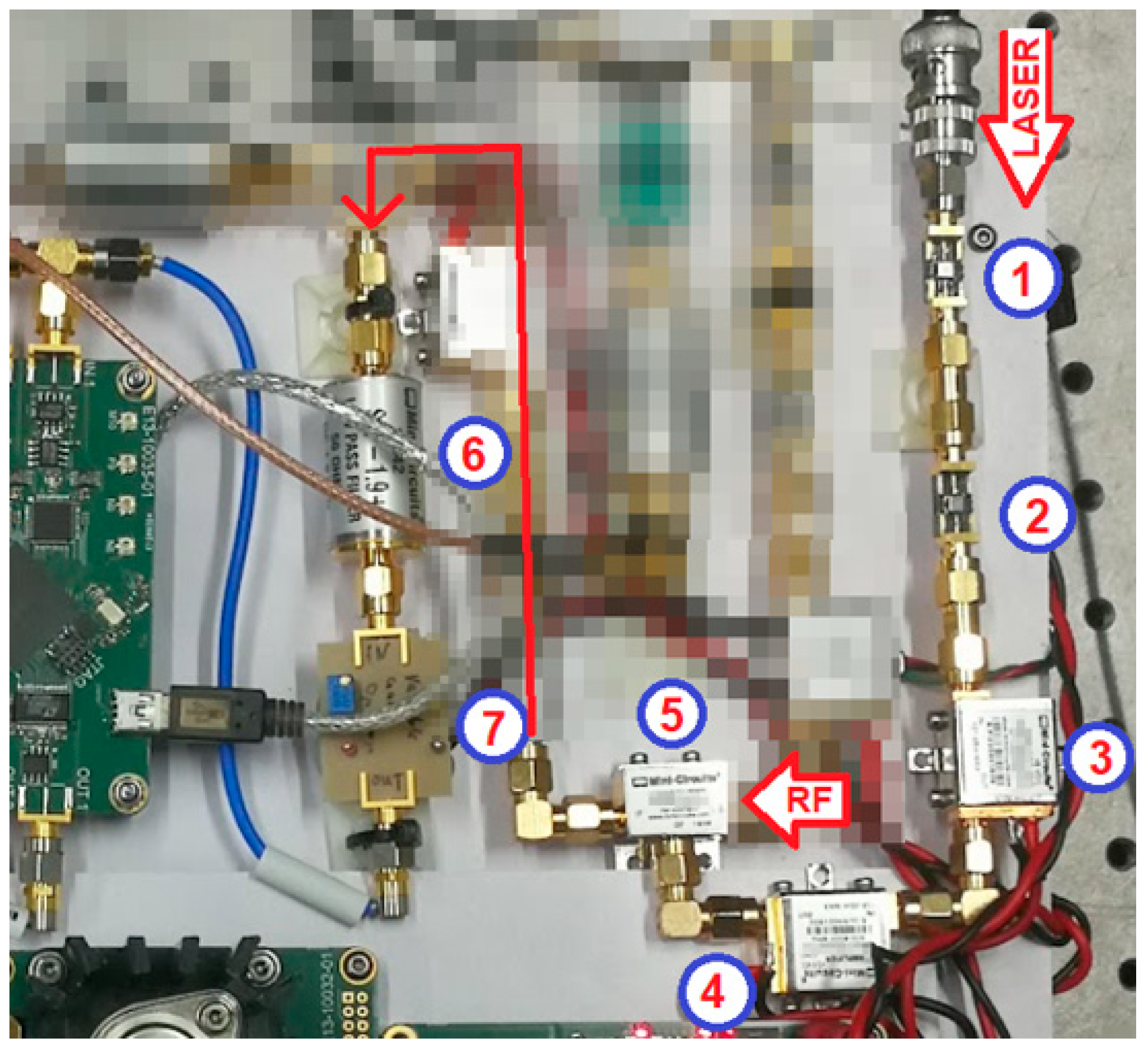
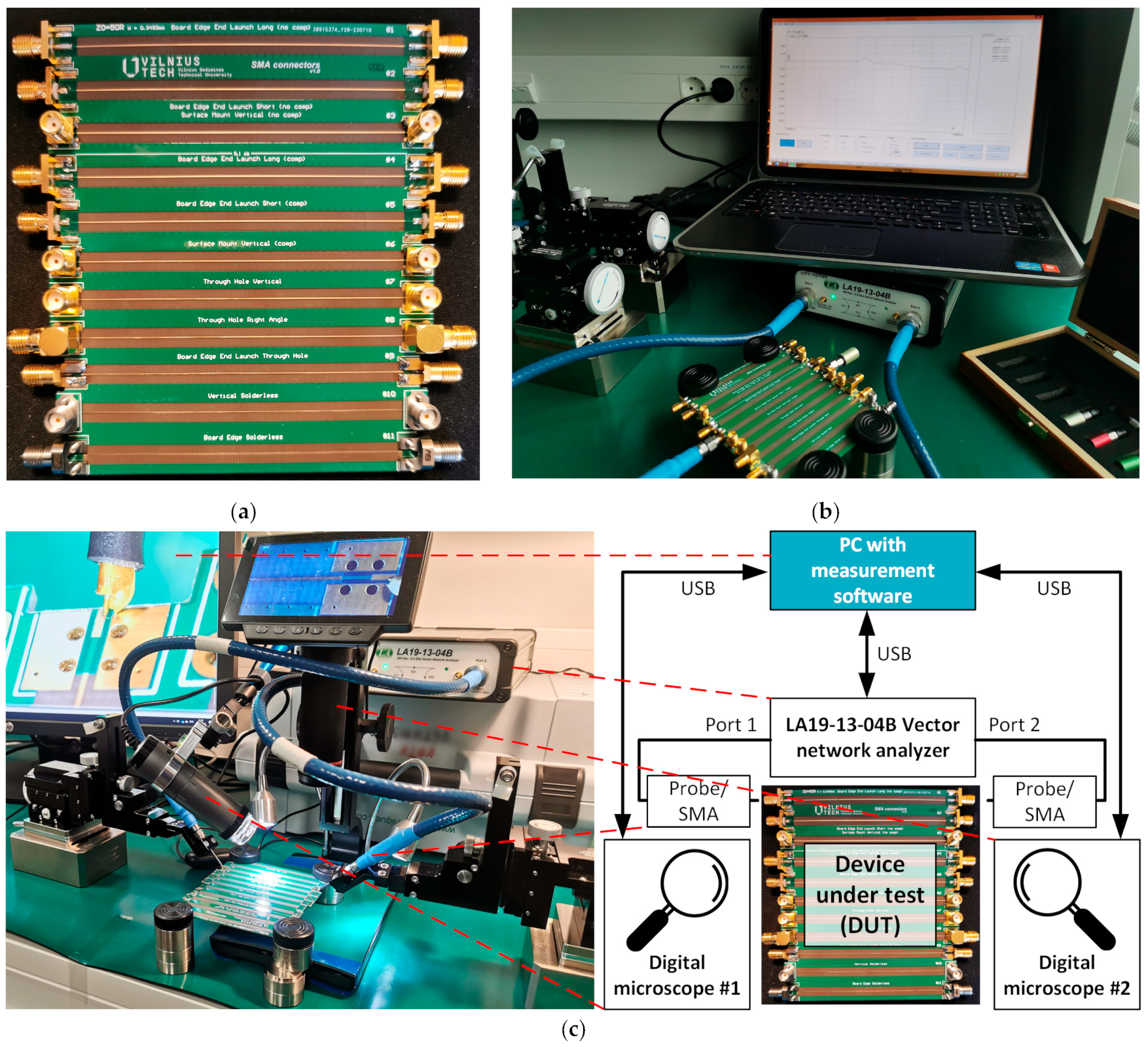
2. Measurement Set-Up

The main scope of this paper is to measure the most common SMA connector types, which require soldering to be mounted on a PCB. These include SMD and through-hole in right angle, edge-mount, and vertical variations. The results are compared with the performance of edge-mount and vertical solderless connectors, which are mounted on a PCB only via compression. Each of the connectors, listed in Table 1, was measured using a calibrated 8.5 GHz bandwidth LA19-1304B VNA, and both reflection coefficient S11 and transfer coefficient S21 parameters, as well as TDR response, were logged. All listed SMA connectors were purchased by an official vendor and were selected to have identical parameters: jack (female socket) type with an impedance of 50 Ω, the center contact material is beryllium copper, and the dielectric material is polytetrafluoroethylene (PTFE). The only difference is the frequency rating of each connector, which is also included in Table 1. However, the difference in rated frequency does not affect the measurement results, as all measurements were conducted at up to 8 GHz.
Another parameter, which is present in Table 1, is the relative connector price. It was calculated based on the price of the through-hole vertical (No. #7), which is one of the oldest and most common SMA connector types. All other connector prices were compared with the latter when purchasing a single unit and in bulk (100 pcs.) from the same vendor. A relative price estimation was chosen, as the market price for electronics components changes rapidly and absolute numbers might become irrelevant even in the near future. SMA connector signal pin land pad dimensions are also presented for each of the selected connectors in Table 1.
Figure 2a presents the printed circuit board (PCB) containing the connectors listed in Table 1, while the measurement set-up is depicted in Figure 2b. In all cases, the Z0 = 50 Ω microstrip line length from the SMA pad on one end to another was held constant and equal to 89 mm. The land pad for each component was designed according to the appropriate datasheet recommendation. Reference plane cut-out impedance discontinuity compensation was also applied to horizontal and vertical surface mount SMA connectors (No. #4–6) in order to improve the frequency response of each one and compare these results with other connector types. The S11 parameter was measured by directly connecting the PCB to the VNA and loading the DUT with a calibration Z0 = 50 Ω load; hence, no cables were used.
Reference S-parameter and TDR measurements were conducted without any SMA connectors. The trace for connector #9 was directly connected to the VNA through a precision probe station PS600 with 20 GHz PacketMicro microwave probes SP-GR-201505. The latter set-up is shown in Figure 2c.

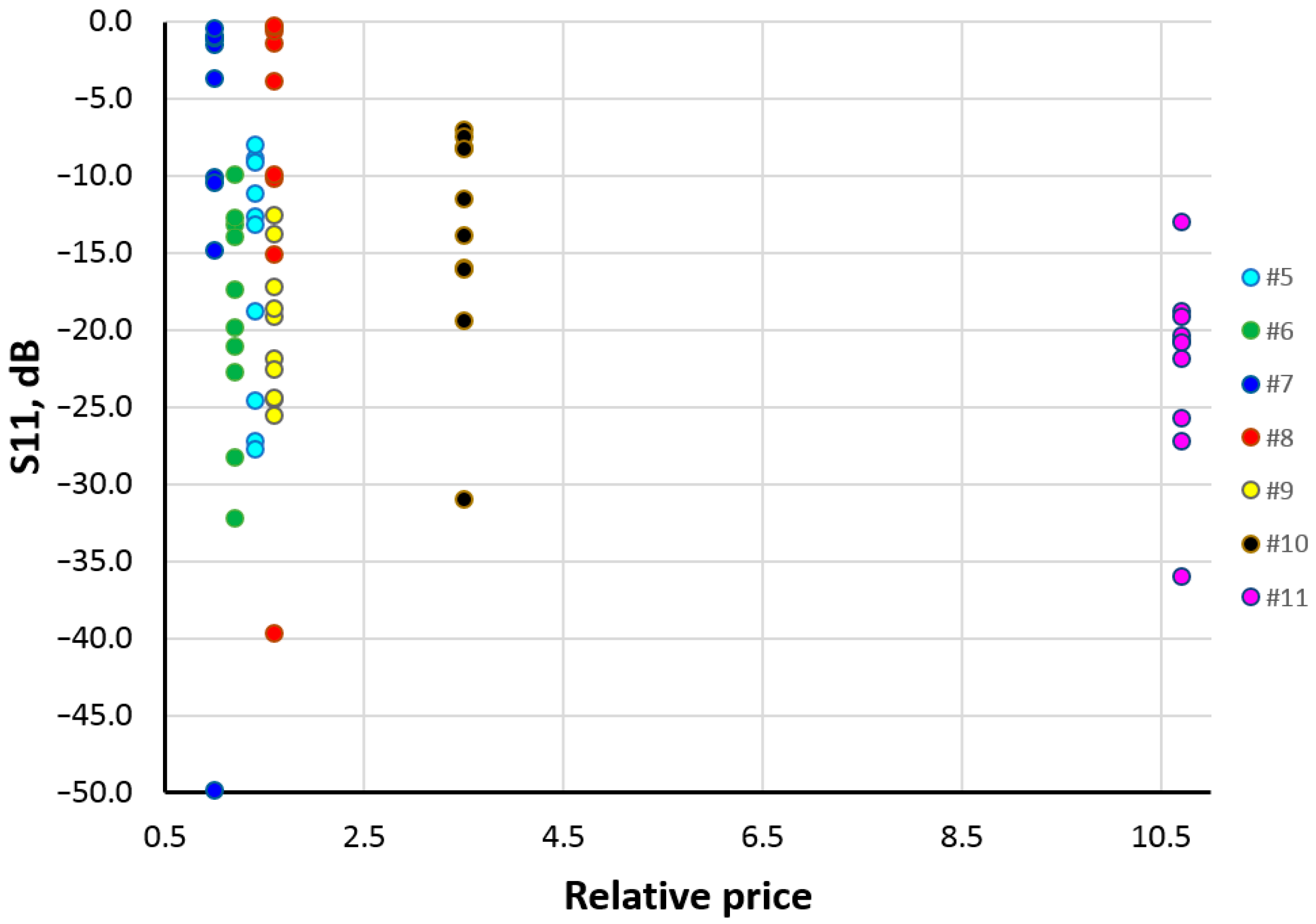
3. Measurement Results and Discussion

Due to the large number of connectors, the results are grouped and presented in accordance with the type of connector, as well as comparing the worst- and best-case performance. S-parameter and TDR responses for the latter three are included in Figure 3 and discussed in this section. The results for other types of SMA connectors in Table 1 are also analyzed and discussed in this section, although the measurement results are provided in Appendix A (Figure A1, Figure A2 and Figure A3). Results for each connector in Table 1 are briefly discussed below, highlighting the ones that exhibit the best and worst parameters, as well as the best cost and performance ratio.

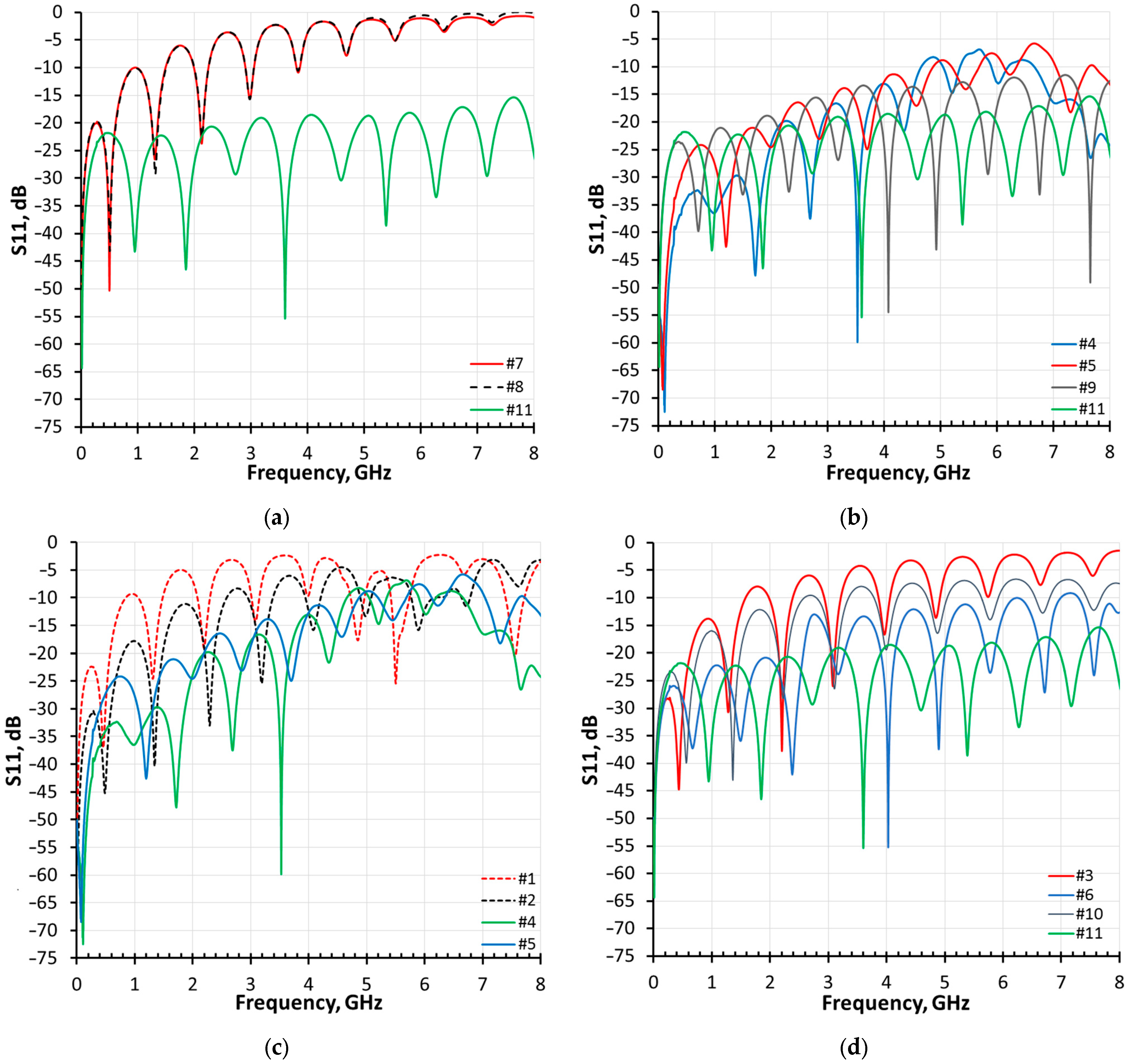
3.1. Measurement Result Analysis

The horizontal board edge end-launch connectors #1 and #2 create a discontinuity, resulting in an impedance offset of more than 25 Ω. This corresponds to S11 < −10 dB only up to 1.5 GHz and with S21 reaching −5 dB at 2.5 GHz for a microstrip with connector #1. As for connector #2, the reflection coefficient S11 < −10 dB is better and reaches 2.5 GHz and S21 = −5 dB at 4.1 GHz. Moreover, it can be seen that the S21 response is not flat. The latter is due to a relatively long signal pin, which requires a large land pad, thus creating an impedance discontinuity. When a reference plane cut-out discontinuity compensation technique [17] is applied, the performance of the same connector types marked as #4 and #5 can be improved. The bandwidth, where the reflection coefficient S11 < −10 dB for microstrips with both #4 and #5, is increased to around 4.5 GHz. Due to a longer signal pin, larger pad, and hence, larger discontinuity, connector #4 reaches S21 = −5 dB at around 5 GHz, whereas connector #5 reaches the same value only at around 6.2 GHz. According to the TDR response in Figure A3, provided in Appendix A, the impedance at connector #4 and #5 cable-to-board transition after applying the compensation drops by 5–10 Ω from the measured target Z0.
Vertical SMD SMA connectors without and with reference plane cut-out discontinuity compensation technique applied correspond to curves #3 and #6. Applying the latter compensation increases the S11 < −10 dB bandwidth from around 1.6 GHz for #3 to practically the full width of 8 GHz. S21 = −5 dB response bandwidth also increases by around 2 GHz. The discontinuity impedance drop is also reduced from around 20 Ω for #3 to around 7 Ω in #6. Therefore, vertical SMA connectors can provide low transition loss only when applying compensation.
Vertical and right-angle through-hole connectors #7 and #8 exhibited the worst responses out of all tested SMA connectors. Microstrips with both types showed identical results, where S11 < −10 dB bandwidth is only 1.5 GHz, S21 = −5 dB is reached at around 3 GHz, and an offset from the target impedance is around 25 Ω. The latter results were expected, as most of the signal pin acts as a stub. The frequency response of these connectors can be increased if the microstrip line is not on the top PCB layer, as in the case of this research, but rather on the bottom. This only shortens the stub, which degrades the performance but does not fully solve the problem.
Connectors #9, #10, and #11 require the smallest size land pad on the PCB; thus, they are expected to outperform all others. For the horizontal board edge end-launch connector #9, which is soldered onto the PCB, the measured S11 response has a maximum value of −12 dB in the whole frequency range, with S21 = −5 dB at around 7 GHz. The TDR shows only a 4 Ω dip in impedance compared with the rest of the microstrip line. Horizontal board edge end-launch solderless connector #11 exhibits the best-measured characteristics—the worst-case S11 value is −16 dB and the insertion loss S21 > −4.2 dB in the whole frequency range. This leads to practically no impedance drop seen in the TDR compared with the measured Z0 of the microstrip. The measured vertical solderless connector performed in between vertical SMA with (#6) and without (#3) impedance compensation, with S11 < −10 dB spanning up to 3.3 GHz and S21 reaching −5 dB value 4.2 GHz.
It is to be noted that the S-parameter measurement results in Figure 3a,b, as well as Figure A1 and Figure A2 in Appendix A, include losses in the microstrip itself, as the microstrip has not been de-embedded. The reason for this is to provide a relative comparison between the connectors with recommended land pads under the same conditions. Thus, the presented S-parameter responses do not directly characterize each tested connector type. They rather serve as a data set comparing the same microstrips with different connectors in the frequency domain. A more precise picture is depicted in TDR responses, as they clearly highlight the SMA-to-microstrip transition impedance. A TDR response for each of the tested connectors is shown in Figure 3c and Figure A3 in Appendix A.

3.2. Linking Measurement Results with Connector Mechanics

The difference in the transition performance from various types of SMA connectors to the microstrip can be elaborated by comparing the physical size of the signal pin in each case and the way this pin interacts with the land pad. It should be mentioned that all measured connectors are rated up to at least 18 GHz, as mentioned in Table 1; thus, it is considered that the sole connectors exhibit the declared performance.
Surface mount end-launch SMA connectors #1, #2, #9, and #10 all have different length and thickness signal pins. The thickness of the pin can alter the transition impedance by adhering to larger amounts of solder and by affecting the width of the required land pad. The length of the pin, however, increases the required length of the land pad. All in all, a larger signal pin requires a larger land pad, which, in turn, creates a discontinuity in the transmission line. So, even though the connector itself is rated to 18 GHz or higher, this discontinuity becomes the bottleneck, which greatly limits the bandwidth. The same principle is applied to SMD vertical SMAs.
The signal pin in through-hole SMA connectors #7 and #8 is soldered to the PCB in a way that is by default creating a stub. The stub is longer when the microstrip is located on the same side the connector is mounted on and shorter on the other. This results in a lower bandwidth in the first case and a slightly higher one in the second. All in all, if the signal pin is not modified (shortened manually), through-hole connectors are not expected to reach the full claimed bandwidth.
Finally, solderless connectors have a small signal pin, which requires a small contact pad and no solder; thus, the transition impedance offset is not limited by the footprint.

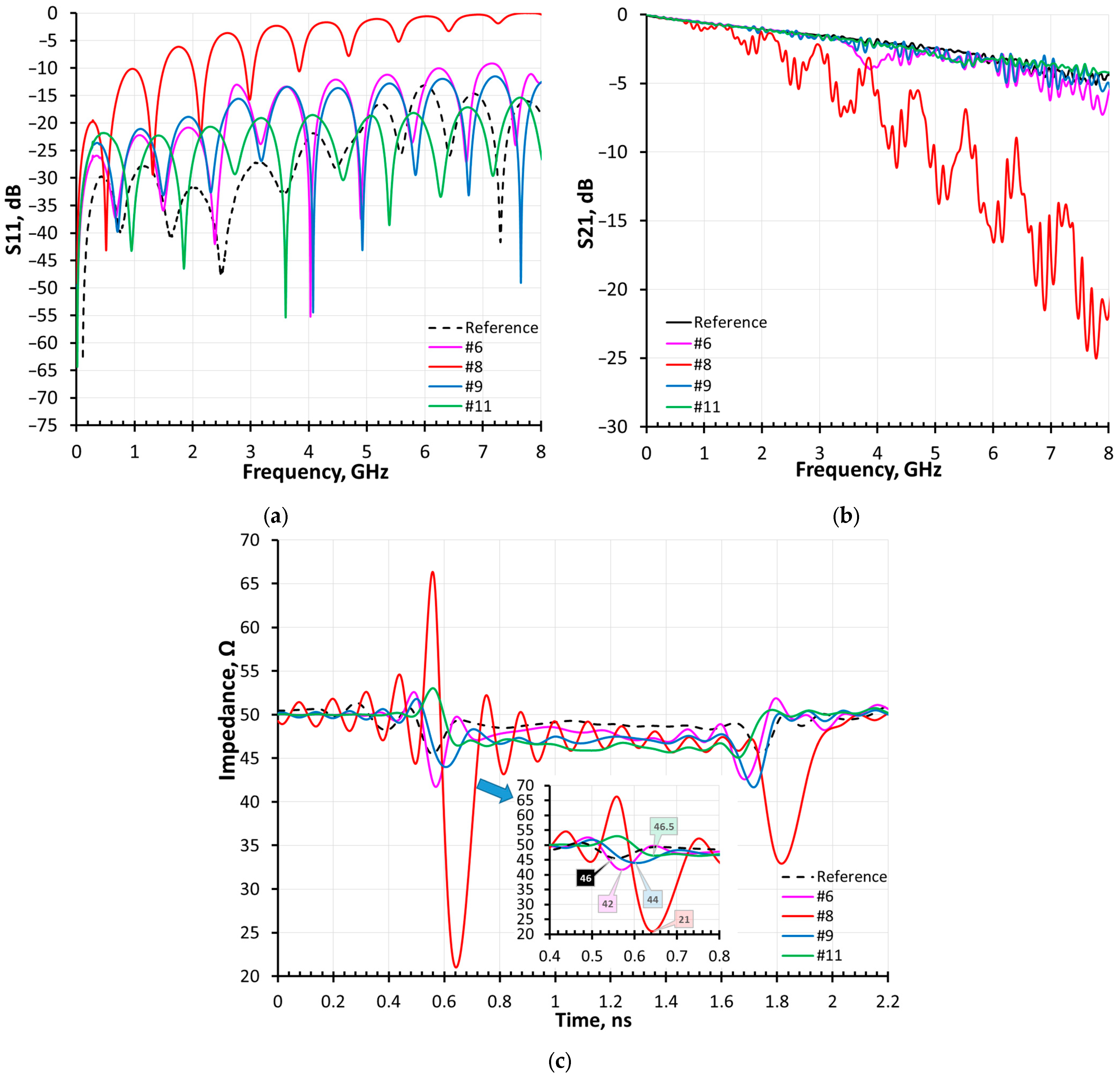
3.3. Most Prominent SMA Connector Types

A summarized comparison between identical microstrip lines with the best-case, worst-case, and most cost-efficient SMA connectors is presented in Figure 3. Reflection coefficient S11 is given in Figure 3a, return loss S21 is provided in Figure 3b, and the TDR response, highlighting the impedance of each connector type, is shown in Figure 3c. Through-hole right-angle SMA connector #8 provides the narrowest bandwidth and largest impedance offset from the target due to the stub and large land pad. The widest bandwidth and smallest impedance offset for the best relative price was achieved in the set-ups that used vertical SMA connectors with impedance compensation #6 and board edge connector #9. The best achieved results were gathered with a solderless board edge SMA connector, presenting the only disadvantage of the largest relative price. A summary describing the best-measured SMA connectors, presented in Figure 3 along with their parameters, is provided in Table 2.
The performance of different SMA connectors versus their relative price is presented in Figure 4. The latter plot presents the S11 parameter at frequencies from 0.5 GHz to 8.5 GHz with a step of 1 GHz for most of the connectors in Table 1, and all connectors summarized in Table 2. All connectors from Table 1 are not included in order not to obstruct readability. It is evident that the best-performing SMA connector, #11, has an S11 response that is almost constant and close to −20 dB over the whole frequency span. On the other hand, the worst-case SMA connector’s (#8) S11 response was centered more around the [−5…−10] dB range, with better performance only at the lower frequency range.

4. Conclusions

In conclusion, this research provides a review and a comprehensive examination of SMA connectors for sub-10 GHz operations, shedding light on their performance and suitability for high-frequency electronic systems. Through extensive S-parameter and time-domain reflectometry measurements, various SMA connector constructions were evaluated, revealing insights into their strengths and limitations. This study highlighted the impact of different SMA connector types on signal integrity when mounted on PCB land pads, providing valuable comparisons for engineers and researchers. Additionally, exploring reference plane cut-outs for discontinuity impedance compensation showed potential for enhancing the frequency response of SMA connectors. SMD vertical, soldered, and solderless board edge end-launch connectors were measured to have 42 Ω, 44 Ω, and 46.5 Ω connector-to-microstrip transition impedance, respectively. In order to achieve the latter transition impedance, the reference plane cut-out compensation has to be applied to the vertical SMA land pad. Moreover, the bandwidth where S11 < −10 dB was measured to be more than 8 GHz for both board edge connectors and 7 GHz for the vertical connector. The worst performance with a bandwidth of only 1.5 GHz and a transition impedance of 21 Ω was achieved using a through-hole right-angle SMA connector. By linking measured performance parameters with relative market prices, the research also provided insights into the economic viability of SMA connectors, with the vertical SMD and board edge end-launch SMA connector types providing the best performance for the smallest relative price. Overall, this study contributes to advancing the understanding and selection of SMA connectors for RF applications across diverse industries, such as telecommunications, aerospace, and medical devices. Future research could explore specific applications in greater depth and further optimize SMA connector designs for enhanced performance and cost-effectiveness.

Author Contributions

Conceptualization, A.V. and V.B.; methodology, A.V. and V.B.; investigation, M.J. and D.G.; writing—original draft preparation, A.V. and V.B.; writing—review and editing, M.J. and D.G. All authors have read and agreed to the published version of the manuscript.

Funding

This research received no external funding.

Institutional Review Board Statement

Not applicable.

Informed Consent Statement

Not applicable.

Data Availability Statement

Not applicable.

Conflicts of Interest

The authors declare no conflicts of interest.

Appendix A

Figure A1. SMA connector S11 response: (a) through-hole #7/#8 vs. solderless edge mount #11, (b) edge mount (#4, #5 with compensation) vs. solderless #11, (c) edge mount without compensation (#1, #2) vs. with compensation (#4, #5), and (d) vertical SMD (#3, #6) vs. solderless (#10, #11).
Electronics 13 02686 g0a1
Figure A2. SMA connector S21 response: (a) through-hole #7/#8 vs. solderless edge mount #11, (b) edge mount (#4, #5 with compensation) vs. solderless #11, (c) edge mount without compensation (#1, #2) vs. with compensation (#4, #5), and (d) vertical SMD (#3, #6) vs. solderless (#10, #11).
Electronics 13 02686 g0a2
Figure A3. SMA connector TDR response: (a) through-hole #7/#8 vs. solderless edge mount #11, (b) edge mount (#4, #5 with compensation) vs. solderless #11, (c) edge mount without compensation (#1, #2) vs. with compensation (#4, #5), and (d) vertical SMD (#3, #6) vs. solderless (#10, #11).
Electronics 13 02686 g0a3

References

  1. Chettri, L.; Bera, R. A Comprehensive Survey on Internet of Things (IoT) Toward 5G wireless systems. IEEE Internet Things J. 2020, 7, 16–32. [Google Scholar] [CrossRef]
  2. Biswas, S.; Sanyal, A.; Božanić, D.; Puška, A.; Marinković, D. Critical Success Factors for 5G Technology Adaptation in Supply chains. Sustainability 2023, 15, 5539. [Google Scholar] [CrossRef]
  3. Paleček, J.; Vestenický, M.; Vestenický, P.; Spalek, J. Examination of SMA connector parameters. In Proceedings of the 2012 IEEE 16th International Conference on Intelligent Engineering Systems (INES), Lisbon, Portugal, 13–15 June 2012; pp. 259–263. [Google Scholar]
  4. Mandic, T.; Magerl, M.; Baric, A. Sequential Buildup of Broadband Equivalent Circuit Model for Low-Cost SMA Connectors. IEEE Trans. Electromagn. Compat. 2019, 61, 242–250. [Google Scholar] [CrossRef]
  5. Hwang, C.; Ouyang, M.; Fan, J. Bandwidth improvement technique for an edge mount SMA launch structure in multilayer boards. In Proceedings of the 2016 IEEE International Symposium on Electromagnetic Compatibility (EMC), Ottawa, ON, Canada, 25–29 July 2016; pp. 308–311. [Google Scholar]
  6. Hwang, C.; Ouyang, M.; Fan, J. Return Path Discontinuity Analysis of an Edge Mount SMA Launch Structure in Multilayer Boards. IEEE Trans. Electromagn. Compat. 2018, 60, 453–458. [Google Scholar] [CrossRef]
  7. Khan, A.A.; Mandal, M.K.; Shaw, R. A compact and wideband SMA connector to empty substrate integrated waveguide (ESIW) transition. In Proceedings of the 2015 IEEE MTT-S International Microwave and RF Conference (IMaRC), Hyderabad, India, 10–12 December 2015; pp. 246–248. [Google Scholar]
  8. Zha, H.; Lu, D.; Wang, W.; Lin, F. RF modeling and optimization of end-launch SMA to trace transition. In Proceedings of the 2015 IEEE 17th Electronics Packaging and Technology Conference (EPTC), Singapore, 2–4 December 2015; pp. 1–4. [Google Scholar]
  9. Ben, R.; Hu, S.; Li, X.; Fu, Z. Signal intergrity analysis for SMA via on the PCB. In Proceedings of the 2017 IEEE 9th International Conference on Communication Software and Networks (ICCSN), Guangzhou, China, 6–8 May 2017; pp. 865–869. [Google Scholar]
  10. Diewald, A.R.; Müller, S.; Olk, A. PCB-side matching networks for coaxial connectors. In Proceedings of the 2017 Antenna Measurement Techniques Association Symposium (AMTA), Atlanta, GA, USA, 15–20 October 2017; pp. 1–5. [Google Scholar]
  11. Magerl, M.; Mandic, T.; Baric, A. Broadband characterization of SMA connectors by measurements. In Proceedings of the 2014 37th International Convention on Information and Communication Technology, Electronics and Microelectronics (MIPRO), Opatija, Croatia, 26–30 May 2014; pp. 104–109. [Google Scholar]
  12. MIL-C-39012C, Military Specification: Connectors, Coaxial, Radio Frequency, General Specification for (11 Aug 1982). Available online: http://everyspec.com/MIL-SPECS/MIL-SPECS-MIL-C/MIL-C-39012C_28968/ (accessed on 7 July 2024).
  13. Amphenol RF “SMA Connectors”. Available online: https://www.amphenolrf.com/rf-connectors/sma-connectors.html (accessed on 7 March 2024).
  14. Unleashing the Power of SMA Connectors: A Key Component for Seamless Signal Transmission. Available online: https://www.elecrow.com/blog/unleashing-the-power-of-sma-connectors-a-key-component-for-seamless-signal-transmission.html (accessed on 7 March 2024).
  15. Exploring the Wide Range of Applications for SMA Connectors. Available online: https://www.elecbee.com/en-2532-exploring-the-wide-range-of-applications-for-sma-connectors (accessed on 7 March 2024).
  16. Šapalas, J. Improvement and Research of Femtosecond Laser Pulse Recurrence Frequency Tuning System. Master’s Thesis, Vilnius Gediminas Technical University (VILNIUS TECH), Vilniaus, Lithuania, 2023; 39p. [Google Scholar]
  17. Barzdenas, V.; Vasjanov, A. A Method of Optimizing Characteristic Impedance Compensation Using Cut-Outs in High-Density PCB Designs. Sensors 2022, 22, 964. [Google Scholar] [CrossRef] [PubMed]
Figure 1. SMA connectors in a laser set-up [16].
Electronics 13 02686 g001
Figure 2. Device under test: (a) printed circuit board; (b) connector; and (c) reference measurement set-up and block diagram.
Electronics 13 02686 g002
Figure 3. Best-case, worst-case, and most cost-efficient SMA connector: (a) reflection coefficient S11; (b) transfer coefficient S21; and (c) TDR response.
Electronics 13 02686 g003
Figure 4. Relative price vs. performance (S11 parameter scattering at various frequencies) for different SMA connectors.
Electronics 13 02686 g004
Table 1. SMA connector summary.
No.SMA Connector Type *
(Land Pad Dimensions)
SMA
Connector Mounting
Max.
Frequency, GHz
Pad Impedance
Discontinuity Compensated
Relative Connector Price
for 1 pcs. (100 pcs.)
#1Board edge 1
(4.5 × 1.5 mm2 pad)
End launch18No1.6 (1.6)
#2Board edge 2
(2.3 × 1.5 mm2 pad)
1.4 (1.4)
#3SMD
(⌀2.05 mm pad)
Vertical1.2 (1.1)
#4Board edge 1
(4.5 × 1.5 mm2 pad)
End launchYes1.6 (1.6)
#5Board edge 2
(2.3 × 1.5 mm2 pad)
1.4 (1.4)
#6SMD
(⌀2.05 mm pad)
Vertical1.2 (1.1)
#7Through-hole
(⌀3 mm pad)
VerticalNo1.0 (1.0)
#8Through-hole
(⌀3 mm pad)
Right angle1.6 (1.5)
#9Board edge 3
(2 × 0.55 mm2 pad)
End launch26.51.6 (1.6)
#10Solderless
(⌀0.7 mm pad)
Vertical,
compression
273.5 (2.6)
#11Solderless
(0.7 × 0.5 mm2 pad)
End launch,
compression
26.510.7 (10.8)
* Note: All connectors were purchased from a single authorized vendor.
Table 2. Best-measured SMA connector performance.
ParameterConnector Type
No. Reference#6#9#11
SMA connector type
(land pad dimensions)
-SMD
(⌀2.05 mm pad)
Board edge 3 (2 × 0.55 mm2 pad)Solderless
(0.7 × 0.5 mm2 pad)
SMA connector mounting-VerticalEnd launchEnd launch, compression
Max. frequency, GHz-1826.5
Pad impedance discontinuity compensated-YesNo
Relative connector price,
buying 1 pcs. (100 pcs.)
-1.2 (1.1)1.6 (1.6)10.7 (10.8)
Measured impedance at SMA connector to board Z0, measured ≈ 48 Ω microstrip transition, Ω46
(RF probes)
424446.5
S11 < −10 dB bandwidth *, GHz>87>8>8
Minimum S11 over measured
8 GHz bandwidth *, dB
−14−9−12−15
S21 = −3 dB bandwidth *, GHz63.64.55.1
S21 = −5 dB bandwidth *, GHz>86.16.17.5
* Note: Value includes microstrip.
Disclaimer/Publisher’s Note: The statements, opinions and data contained in all publications are solely those of the individual author(s) and contributor(s) and not of MDPI and/or the editor(s). MDPI and/or the editor(s) disclaim responsibility for any injury to people or property resulting from any ideas, methods, instructions or products referred to in the content.

