Article

Research on an Active Adjustment Mechanism Based on Non-Singular Terminal Sliding Mode and Finite-Time Disturbance Observer

1
Changchun Institute of Optics, Fine Mechanics and Physics, Chinese Academy of Sciences, Changchun 130033, China
2
University of Chinese Academy of Sciences, Beijing 100049, China
3
State Key Laboratory of Applied Optics, Changchun Institute of Optics, Fine Mechanics and Physics, Chinese Academy of Sciences, Changchun 130033, China
4
Key Laboratory of Optical System Advanced Manufacturing Technology, Chinese Academy of Sciences, Changchun 130033, China
*
Authors to whom correspondence should be addressed.
Electronics 2024, 13(14), 2794; https://doi.org/10.3390/electronics13142794
Submission received: 27 May 2024 / Revised: 11 July 2024 / Accepted: 14 July 2024 / Published: 16 July 2024

Abstract

:
With the continuous development of synchrotron radiation light sources, higher requirements have been put forward for the stability of double-crystal monochromators in synchrotron radiation facilities. This paper designs an active adjustment mechanism for a double-crystal monochromator to improve its stability. Firstly, three spatial degrees of freedom are designed based on the active adjustment mechanism of flexible leaf spring parallel coupling, and the prototype of the mechanism is fabricated. Secondly, system identification experiments are carried out and the system transfer function curve is fitted by the nonlinear least squares method. Thirdly, the controller based on non-singular terminal sliding modes and a finite-time disturbance observer was designed for stability control and disturbance compensation. Finally, the effectiveness of the controller is verified by a model-in-the-loop approach based on the performance of the real-time target machine. The results show that the non-singular terminal sliding mode + finite-time disturbance observer control strategy can reduce the RMS value of the vibration displacement of Axis-1/Axis-2/Axis-3 by 81.25%, 78.53%, and 71.82%.

1. Introduction

Synchrotron radiation light sources are widely used in basic research in physics, chemistry, biology, medicine, and materials and information science owing to their excellent characteristics of a broad spectrum, high brightness, high collimation, and high purity [1,2,3,4,5,6,7]. A double-crystal monochromator is an optical device that separates the multi-wavelength light emitted from the synchrotron light source into the required monochromatic light, and it is the core device of the synchrotron beamline station. For hard X-synchrotron beamlines, the spot quality is directly related to the performance level of the double-crystal monochromator [8]. The beam separation principle of the crystal monochromator is mainly based on the Bragg diffraction principle to achieve a monochromatic light output of different wavelengths. The principle is shown in Figure 1. The change in Bragg angle can make the wavelength of the emitted light variable, and the relationship between the Bragg angle and the emitted wavelength is:
2 d sin θ = n λ
where n is the diffraction level, d is the crystal lattice constant, λ is the wavelength and θ is the Bragg angle. The double-crystal monochromator can adjust the wavelength and energy of the emitted light by adjusting the Bragg angle to meet the different requirements of the experiment.
The relative stability of the first and second crystals changes owing to the cooling system. As a result, the position stability of the focused spot, the stability of the output energy, and the luminous flux during energy scanning would be affected [8,9,10]. Generally, improving the stability of hard X-ray optical devices through passive control is one of the common technical methods. Yamazaki H et al. optimized the cooling system pipeline to achieve the theoretical stability of the double-crystal monochromator to 50 nrad. [11] optimized the cooling system pipeline layout, and the measured stability of the double-crystal monochromator turned out to be less than 200 nrad. [12] designed a cradle structure, and the stability of the double-crystal monochromator stability reached about 30 nrad within the bandwidth of 0.1–100 Hz. [13] designed a fine-adjustment mechanism and investigated the effect of mechanical parameters on the natural frequency of the adjustment mechanism [14]. Noriyuki Igarashi applied damping materials and reduced the impact of foundation vibration on a double-crystal monochromator by optimizing its size [15].
The purpose of this paper is to develop an active adjustment mechanism based on flexible leaf springs with three spatial degrees of freedom, which is used to improve the stability of double-crystal monochromators for synchrotron light sources. Firstly, the active adjustment mechanism was designed and its prototype was fabricated. Secondly, the system identification experiments were carried out and the system transfer function curve was fitted using a nonlinear least squares system identification method. Finally, a control strategy based on the non-singular terminal sliding mode (NTSM) control method was designed, and a finite-time disturbance observer (FT-DOB) was designed to compensate for the system disturbance. The effectiveness of the adopted control strategy is verified by model-in-the-loop tests. Meanwhile, the control performance of conventional sliding mode control (C-SMC), conventional sliding mode control + finite-time disturbance observer (C-SMC + FT-DOB), non-singular terminal sliding mode (NTSM) control, and non-singular terminal sliding mode control + finite-time disturbance observer (NTSM + FT-DOB) were compared.

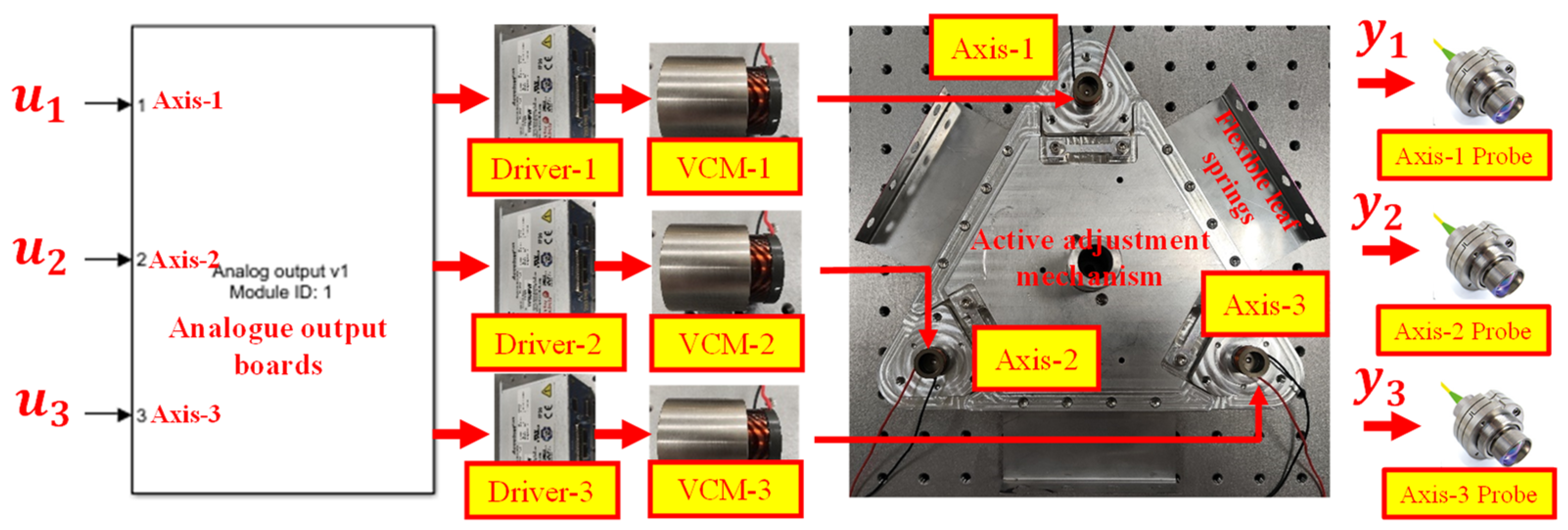
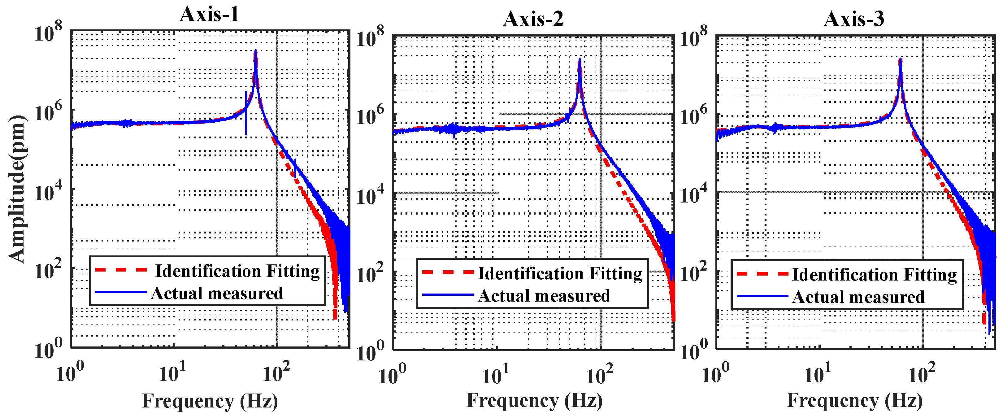
2. System Identification Experiment

The basic structure of the double-crystal monochromator based on the active control method is shown in Figure 2. Three voice coil motor actuators are mounted on the second crystal active adjustment mechanism. Three probes of the laser interferometer are mounted on a second crystal active adjusting mechanism in an even 120-degree pattern. The reflector assembly is mounted on the first crystal in an even 120-degree pattern. Three sets of sensor probes measure the relative displacement deviation between the first crystal and the second crystal. The control system calculates the voice coil motor drive voltage signal in real-time according to the relative deviation. It drives the motor to work after amplification, rectification, and filtering by the driver, which can eliminate the displacement deviation between the first crystal and the second crystal.
The purpose of the system identification experiments is to create an accurate and efficient model of the system, which is a prerequisite for achieving high-quality control of the active adjustment mechanism. The experimental diagram of system identification is shown in Figure 3. This paper uses the nonlinear least squares system identification method to estimate the open-loop transfer function from the input voltage signal u i   i = 1 , 2 , 3 to the output displacement y i ( i = 1 , 2 , 3 ) . (Note: u i   i = 1 , 2 , 3 is the input voltage of A x i s   i   ( i = 1 , 2 , 3 ) and y i   ( i = 1 , 2 , 3 ) is the displacement of A x i s   i   ( i = 1 , 2 , 3 ) ). The relative displacement measured by the laser interferometer probe has been schematically labeled in Figure 2. During the experiment, a frequency modulation sinusoidal signal with a linear increase from 0.1 Hz to 500 Hz and an amplitude of 0.1 v is selected as the input of each axis. At the same time, the other two axes maintained 0 input. The displacement output of each axis is measured by a laser displacement sensor with Pico-meter displacement resolution, and the sampling frequency is 1000 Hz. In particular, the laser interferometer used in this research is equipped with an optical system compensation unit, along with the possibility of selecting low-pass filters with different cut-off frequencies (the cut-off frequency of the low-pass filter selected in this research is 80 Hz). To verify the correctness of the identified system transfer function, the measured open-loop frequency response curves of the three axes’ frequency responses are fitted to the identified system open-loop transfer function curve, as shown in Figure 4. From Figure 4, it can be seen that the first-order natural frequency of the system is about 60 Hz. In particular, the system transfer function obtained based on the nonlinear least squares identification method has high accuracy in the range of 0–100 Hz. It can be seen from Figure 4 that the Axis-1/Axis-2/Axis-3 transfer functions identified in this paper can reflect the system characteristics to a certain extent, which provides a theoretical basis for the subsequent controller design.

3. Controller Design

3.1. System Resonance Suppression Methods

From Figure 4, it can be seen that the system has a second-order resonance at about 60 Hz. The value of the damping ratio determines the magnitude of the resonance peak of the system. The smaller the damping ratio, the larger the resonance peak of the system; the larger the damping ratio, the smaller the resonance peak of the system. The existence of resonance peaks can result in many difficulties in controller design. Generally, the main methods to eliminate the resonance peaks are velocity feedback and the design of notch filters. The second-order system transfer function expression is:
G ( s ) = k ω n 2 s 2 + 2 ξ ω n s + ω n 2
where ω n is the resonant frequency and ξ is the damping ratio. After adding the velocity feedback link, the system transfer function expression is:
G ( s ) = k ω n 2 s 2 + ( 2 ξ + α k ) ω n s + ω n 2
where α is the velocity factor. Equation (3) shows that the velocity feedback link serves to increase the damping from the original damping of the model. Therefore, the damping ratio can be tuned by adjusting the value of α .
In order to better suppress the second-order resonance of the system, this paper designs a notch filter based on the velocity feedback link with the following expression:
N ( s ) = s 2 + 2 ξ n 1 ω n s + ω n 2 s 2 + 2 ξ n 2 ω n s + ω n 2
where ω n is the system resonant frequency, ξ n 1 is the system damping ratio after velocity feedback, and ξ n 2 is the optimum damping ratio ( ξ n 2 = 0.7 ). The frequency response after speed feedback and notch filtering is shown in Figure 5. The results show that using this method can effectively suppress system resonance and make controller design easier.

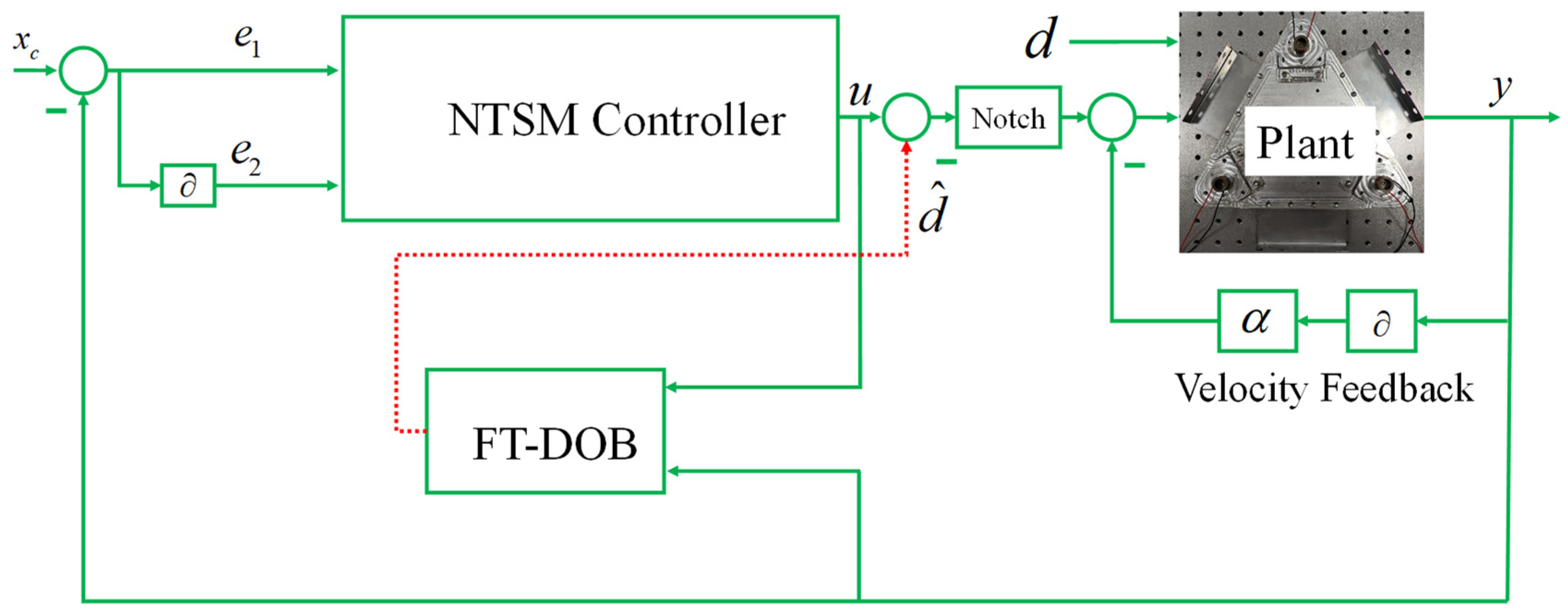
3.2. NTSM + FT-DOB Control Strategy

The difference between NTSM and C-SMC is that the sliding surface of the sliding mode is selected as a nonlinear function, ensuring that the system state converges to zero in finite time when it reaches the sliding surface [16,17,18]. In this paper, a finite time disturbance observer is designed to estimate and compensate for the disturbance in the system to reduce the effect of sliding mode controller jitter and suppress the external cooling system and internal coupling disturbance. The controller design and control block diagram are shown in Figure 6. The state space equation for Axis-1/Axis-2/Axis-3 is:
{ x ˙ 1 = x 2 x ˙ 2 = f ( x ) + b u + d ( t )
where d ( t ) is the system uncertainty, coupling disturbance, and disturbance from the cooling system. f ( x ) is a function of the system state. b is a constant.
Theorem 1. 
There exists the following equation [19]:
{ λ ˙ 1 = λ 2 β 1 | λ 1 | ( α + 1 ) / 2 s i g n ( λ 1 ) λ ˙ 2 = λ 3 β 2 | λ 1 | ( α + 1 ) / 2 s i g n ( λ 1 ) λ ˙ 3 = L β 3 | λ 1 | α s i g n ( λ 1 )
where  λ 1 ,  λ 2 ,  λ 3  are the states of the system.  β 1 ,  β 2 ,  β 3  are positive constants. If  0 < α < 1 , the system is stable in finite time.  L  is a generalized disturbance.
Theorem 2. 
There exists the following equation [20]:
{ η ˙ 1 = η 2 β 1 s i g n ( η 1 ) | η 1 | α 1 η ˙ 2 = η 3 β 2 s i g n ( η 1 ) | η 1 | α 2 η ˙ 3 = β 3 s i g n ( η 1 ) | η 1 | α 3
Equation (7) is finite-time stable when  β 1 β 2 β 3 > 0 , 2 3 < α < 1  is satisfied.
Considering Equation (5), the designed finite-time disturbance observer is:
{ y ˙ 1 ( t ) = y 2 ( t ) β 1 s i g n ( y 1 ( t ) x 1 ( t ) ) | y 1 ( t ) x 1 ( t ) | 0.975 y ˙ 2 ( t ) = y 3 ( t ) β 2 s i g n ( y 1 ( t ) x 1 ( t ) ) | y 1 ( t ) x 1 ( t ) | 0.975 + b u y ˙ 3 ( t ) = β 3 s i g n ( y 1 ( t ) x 1 ( t ) ) | y 1 ( t ) x 1 ( t ) | 0.95
where β 1 , β 2 , β 3 are the observation gains; y 1 , y 2 , y 3 are the observations. Let the observation error e i = y i ( t ) x i ( t ) , i = 1 , 2 , 3 , the observation error system equation is:
{ e ˙ 1 ( t ) = e 2 ( t ) β 1 s i g n ( e 1 ( t ) ) | e 1 ( t ) | 0.975 e ˙ 2 ( t ) = e 3 ( t ) β 2 s i g n ( e 1 ( t ) ) | e 1 ( t ) | 0.975 e ˙ 3 ( t ) = β 3 s i g n ( e 1 ( t ) ) | e 1 ( t ) | 0.95
According to Theorems 1 and 2, Equation (9) is finite-time stable.
The displacement error and its derivative are
{ e 1 = x c y 1 e 2 = x ˙ c y ˙ 1
where x c is the desired displacement ( x c = 0 ). The non-singular slip mode surface is taken as
s = e 1 + 1 β e 2 p / q
where p and q are positive odd numbers.
The non-singular terminal sliding mode control law is designed as follows:
u = 1 b [ f + β q p e 2 2 p / q + ( D + η ) sgn ( s ) ]
where D is the upper bound of the disturbance. 1 < p q < 2 , η > 0 .
Taking the Lyapunov function as
V = 1 2 s 2
Then, there is [21]:
V ˙ = s ˙ s = s ( e 2 + 1 β p q e 2 p q 1 ( f + b u + d ) ) = s ( e 2 + 1 β p q e 2 p q 1 ( f ( f + β q p e 2 2 p q + ( D + η ) sgn ( s ) ) + d ) ) = s ( 1 β p q e 2 p q 1 ( ( D + η ) sgn ( s ) + d ) ) = ( 1 β p q e 2 p q 1 ( s ( D + η ) sgn ( s ) + s d ) )
Since 1 < p q < 2 , β > 0 , and p , q is a positive odd number, there is
s s ˙ 1 β p q e 2 p q 1 ( η | s | ) < 0
when t , s = 0 . Therefore, the controller satisfies the Lyapunov stability condition when e 2 0 .

4. Results and Discussion

To validate the effectiveness of the designed controller, the continuous domain is converted to the discrete domain using the zero-pole matched method, and the model-in-the-loop test is carried out based on the performance of the real-time target machine. In particular, the control performance comparisons of the C-SMC (exponential approaching law and linear sliding surface), C-SMC + FT-DOB, NTSM, and NTSM + FT-DOB control strategies are based on velocity feedback and notch filters.
In this paper, the C-SMC and C-SMC + FT-DOB control strategies and the NTSM and NTSM + FT-DOB control strategies are compared. Figure 7 and Figure 8 show the comparison results of controller outputs for four control strategies under sinusoidal disturbances. Analyzing Figure 7a and Figure 8a, it can be found that there is jitter in the controller output when the C-SMC is applied. When disturbances are present, C-SMC, based on exponential convergence law, can suppress the disturbances by means of a robust term in the switching term. As the disturbance increases, the switching gain keeps increasing, which leads to the more severe jittering of the controller outputs. Generally, disturbance feed-forward compensation by a disturbance observer to reduce the disturbance can reduce the sliding mode control jitter, and the effectiveness of this approach is sufficiently demonstrated in Figure 7b and Figure 8b. From Figure 7c and Figure 8c, it is known that compared with the C-SMC, the NTSM jitter phenomenon is significantly weaker, the reason is that the NTSM has no switching term, which can largely eliminate the jitter. Furthermore, the controller output of the NTSM + FT-DOB control strategy is more stable as shown in Figure 7d.
The stability results of Axis-1/Axis-2/Axis-3 under C-SMC, C-SMC + FT-DOB, NTSM, and NTSM + FT-DOB control strategies are shown in Figure 9. Intuitively, the active control method is effective in reducing the vibration amplitude compared with uncontrolled. Meanwhile, NTSM + FT-DOB is more effective than the C-SMC, C-SMC + FT-DOB, and NTSM control strategies.
To compare the control performance of the C-SMC, C-SMC + FT-DOB, NTSM, and NTSM + FT-DOB control strategies more intuitively, this paper presents important time-domain indicators, such as maximum, minimum, and RMS values, as shown in Table 1. Firstly, compared to the uncontrolled, the maximum values of the displacements of Axis-1 for C-SMC, C-SMC + FT-DOB, NTSM, and NTSM + FT-DOB decreased by 66.69%, 79.70%, 77.52%, and 80.17%; the minimum values decreased by 66.98%, 78.13%, 75.80%, and 78.81%; and the RMS values decreased by 68.16%, 79.08%, 77.34%, and 81.25%. Secondly, compared to the uncontrolled, the maximum values of the displacements of Axis-2 for C-SMC, C-SMC + FT-DOB, NTSM, and NTSM + FT-DOB decreased by 68.68%, 78.16%, 73.75%, and 79.17%; the minimum values decreased by 68.08%, 77.17%, 73.82%, and 80.12%; and the RMS values decreased by 66.17%, 76.44%, 70.51%, and 78.53%. Lastly, compared to the uncontrolled, the maximum values of the displacements of Axis-3 for C-SMC, C-SMC + FT-DOB, NTSM, and NTSM + FT-DOB decreased by 26.49%, 61.58%, 55.14%, and 67.13%; the minimum values decreased by 26.22%, 56.17%, 55.06%, and 62.89%; the RMS values decreased by 35.80%, 65.73%, 62.17%, and 71.82%. Compared to C-SMC, C-SMC + FT-DOB can reduce the vibration displacement substantially, which proves the effectiveness of the finite-time disturbance observer; the comparison between NTSM and NTSM + FT-DOB can draw the same conclusion. Compared to C-SMC, C-SMC + FT-DOB, and NTSM, the NTSM + FT-DOB control strategy has a significant suppression effect, which sufficiently illustrates the effectiveness of active vibration damping and excellent vibration suppression ability of NTSM + FT-DOB control strategy.

5. Conclusions

In this paper: an active adjustment mechanism with three spatial degrees of freedom based on a flexible leaf spring was designed, and the system transfer function curve was fitted by nonlinear least squares method. The damping ratio of the system was improved based on velocity feedback and notch filtering, which establishes the foundation for the controller design. An active control strategy based on NTSM + FT-DOB was designed, and the effectiveness of the control strategy was verified based on model in-loop experiments. The C-SMC, C-SMC + FT-DOB, and NTSM control strategies were compared and analyzed, and the excellent ability of the NTSM +FT-DOB active control strategy for active vibration suppression was demonstrated. Compared to the sliding mode control without the finite-time disturbance observer, the jitter phenomenon of the sliding mode control with the disturbance observer was drastically reduced. With the C-SMC, C-SMC + FT-DOB, NTSM, and NTSM + FT-DOB control strategies, the displacement RMS values of Axis-1 decreased by 68.16%, 79.08%, 77.34%, and 81.25%; the displacement RMS values of Axis-2 decreased by 66.17%, 76.44%, 70.51%, and 78.53%; with 35.80%, 65.73%, 62.17%, 71.82% decreases in displacement of RMS values for Axis-3. Therefore, the active adjustment mechanism designed and the control strategy adopted in this paper provide a feasible research method for high-stability double-crystal monochromators.

Author Contributions

Y.B. wrote the first draft, performed this experiment, and obtained the data; X.G. supervised the experiment, guided the writing of the paper, revised the manuscript, and provided project support; S.L. designed the mechanics; Q.L. and Y.S. All authors participated in editing the paper. All authors have read and agreed to the published version of the manuscript.

Funding

The work is supported by the National Natural Science Foundation of China (No. 62375261), the National Key Research and Development Program of China (2023YFA1608603), and “The Xu-Guang” Talent Program of Changchun Institute of Optics, Fine Mechanics and Physics (CIOMP), Chinese Academy of Sciences (CAS) (E01672Y6Q0).

Data Availability Statement

The original contributions presented in the study are included in the article, further inquiries can be directed to the corresponding author.

Conflicts of Interest

The authors declare that they have no known competing financial interests or personal relationships that could have appeared to influence the work reported in this paper.

References

  1. Manzanillas, L.; Aplin, S.; Balerna, A.; Bell, P.; Casas, J.; Cascella, M.; Chatterji, S.; Cohen, C.; Dennis, G.; Welter, E.; et al. Development of multi-element monolithic germanium detectors for X-ray detection at synchrotron facilities. Nucl. Instrum. Methods Phys. Res. Sect. A Accel. Spectrometers Detect. Assoc. Equip. 2023, 1047, 167904. [Google Scholar] [CrossRef]
  2. Miki, H.; Hirano, K.; Ninomiya, T.; Arai, Y.; Honda, K. Visualization of temporomandibular joint articular cartilage using synchrotron-radiation X-ray phase-contrast imaging. Nucl. Instrum. Methods Phys. Res. Sect. A Accel. Spectrometers Detect. Assoc. Equip. 2023, 1049, 168005. [Google Scholar] [CrossRef]
  3. Kodama, M.; Takeuchi, A.; Uesugi, M.; Hirai, S. Machine learning super-resolution of laboratory CT images in all-solid-state batteries using synchrotron radiation CT as training data. Energy AI 2023, 14, 100305. [Google Scholar] [CrossRef]
  4. Okonda, J.J.; Angeyo, H.K.; Dehayem-Kamadjeu, A.; Rogena, A.E. Feasibility for early cancer diagnostics by machine learning enabled synchrotron radiation based micro X-ray fluorescence imaging of trace biometals as cancer biomarkers. Spectrochim. Acta Part B At. Spectrosc. 2023, 204, 106671. [Google Scholar] [CrossRef]
  5. Haas, S.; Sun, X.; Conceição AL, C.; Horbach, J.; Pfeffer, S. The new small-angle X-ray scattering beamline for materials research at PETRA III: SAXSMAT beamline P62. J. Synchrotron Radiat. 2023, 30, 1156–1167. [Google Scholar] [CrossRef] [PubMed]
  6. Mandolini, T.; Chantel, J.; Merkel, S.; Le Godec, Y.; Guignot, N.; King, A.; Hosdez, J.; Henry, L.; Hilairet, N. Deformation of two-phase aggregates with in situ X-ray tomography in rotating Paris–Edinburgh cell at GPa pressures and high temperature. J. Synchrotron Radiat. 2023, 30, 962–977. [Google Scholar] [CrossRef] [PubMed]
  7. Ji, T.; Zhu, H.C.; Peng, W.W.; Wang, J.; Zhao, H.W.; Li, A.G.; Chen, M. Infrared microspectroscopy beamline BL06B at SSRF. Nucl. Sci. Tech. 2024, 35, 2. [Google Scholar] [CrossRef]
  8. Fan, Y.; Qin, H.; Zhu, W.; Jia, W.; Liu, Y.; Wang, J.; Li, Z. Angular stability measurement of a cooled double-crystal monochromator at SSRF. Nucl. Instrum. Methods Phys. Res. Sect. A Accel. Spectrometers Detect. Assoc. Equip. 2020, 983, 164636. [Google Scholar] [CrossRef]
  9. Bai, Y.; Gong, X.; Lu, Q.; Song, Y.; Zhu, W.; Xue, S.; Wang, D.; Peng, Z.; Zhang, Z. Adaptive vibration control method for double-crystal monochromator based on VMD and FxNLMS. J. Synchrotron Radiat. 2023, 30, 308–318. [Google Scholar] [CrossRef] [PubMed]
  10. Bai, Y.; Gong, X.; Lu, Q.; Li, S.; Song, Y.; Peng, Z.; Zhang, Z. Research on an active control method of double crystal monochromator with disturbance observer. Nucl. Instrum. Methods Phys. Res. Sect. A 2023, 1057, 168729. [Google Scholar] [CrossRef]
  11. Yamazaki, H.; Matsuzaki, Y.; Shimizu, Y.; Tsuboki, I.; Ikeya, Y.; Takeuchi, T.; Tanaka, M.; Miura, T.; Kishimoto, H.; Ohashi, H.; et al. Challenges toward 50 nrad-stability of X-rays for a next generation light source by refinements of SPring-8 standard monochromator with cryo-cooled Si crystals. In AIP Conference Proceedings; AIP Publishing LLC: Melville, NY, USA, 2019; Volume 2054, p. 060018. [Google Scholar]
  12. Wu, J.; Gong, X.; Song, Y.; Chen, J.; Zhu, W.; Liu, Y.; Fan, Y.; Jin, L. Improvement of the performance of a cryo-cooled monochromator at SSRF. Part II: Angular stability of the exit beam. Nucl. Instrum. Methods Phys. Res. Sect. A Accel. Spectrometers Detect. Assoc. Equip. 2021, 988, 164872. [Google Scholar] [CrossRef]
  13. Qin, H.; Fan, Y.; Zhang, L.; Jin, L.; He, Y.; Zhu, W. Design and stability performance of a cradle type cryo-cooled monochromator at Shanghai Synchrotron Radiation Facility. Nucl. Instrum. Methods Phys.Res. Sect. A Accel. Spectrometers Detect. Assoc. Equip. 2022, 1027, 166350. [Google Scholar] [CrossRef]
  14. Jiang, B.; Zhang, Z.; Zhou, S.; Chu, Y.; Guo, Y. Stability analysis of an angle trimmer mechanism applied to a double crystal monochromator. J. Phys. Conf. Ser. 2023, 2450, 012051. [Google Scholar] [CrossRef]
  15. Igarashi, N.; Ikuta, K.; Miyoshi, T.; Matsugaki, N.; Yamada, Y.; Yousef, M.S.; Wakatsuki, S. X-ray beam stabilization at BL-17A, the protein microcrystallography beamline of the Photon Factor. J. Synchrotron Radiat. 2008, 15, 292–296. [Google Scholar] [CrossRef] [PubMed]
  16. Feng, Y.; Yu, X.H.; Man, Z.H. Non-singular terminal sliding mode control of rigid manipulators. Automatica 2002, 38, 2159–2167. [Google Scholar] [CrossRef]
  17. Zhai, J.; Xu, G. A novel non-singular terminal sliding mode trajectory tracking control for robotic manipulators. IEEE Trans. Circuits Syst. II Express Briefs 2020, 68, 391–395. [Google Scholar] [CrossRef]
  18. Yu, S.; Wu, H.; Xie, M.; Lin, H.; Ma, J. Precise, robust motion control of cell puncture mechanism driven by piezoelectric actuators with fractional-order nonsingular terminal sliding mode control. Bio-Des. Manuf. 2020, 3, 410–426. [Google Scholar] [CrossRef]
  19. Zhao, L.; Zhang, B.; Yang, H.; Wang, Y. Finite-time tracking control for pneumatic servo system via extended state observer. IET Control. Theory Appl. 2017, 11, 2808–2816. [Google Scholar] [CrossRef]
  20. Dong, W. Finite Time Extended State Observer and Its Application. Master’s Thesis, Tianjin University, Tianjin, China, 2017. (In Chinese). [Google Scholar]
  21. Liu, J. Sliding Mode Control Design and Matlab Simulation; Tsinghua University Press: Beijing, China, 2019. [Google Scholar]
Figure 1. Working principle diagram of double crystal monochromator.
Electronics 13 02794 g001
Figure 2. The structure of the double-crystal monochromator designed in this paper, based on the active control method.
Electronics 13 02794 g002
Figure 3. System input signals and output signals in the experiment.
Electronics 13 02794 g003
Figure 4. System frequency response fitting transfer function.
Electronics 13 02794 g004
Figure 5. Frequency response results of the system under speed feedback and notch filtering.
Electronics 13 02794 g005
Figure 6. Block diagram of the control system designed in this paper.
Electronics 13 02794 g006
Figure 7. Controller Outputs (0~0.25 s). (a) C-SMC (b) C-SMC + FT-DOB (c) NTSM (d) NTSM + FT-DOB.
Electronics 13 02794 g007
Figure 8. Controller Outputs (1.6~2 s). (a) C-SMC (b) C-SMC + FT-DOB (c) NTSM (d) NTSM + FT-DOB.
Electronics 13 02794 g008
Figure 9. Comparison results of displacement for Axis-1/Axis-2/Axis-3. (a) Axis-1 (b) Axis-2 (c) Axis-3.
Electronics 13 02794 g009
Table 1. Comparison of max, min, and RMS value results of displacement under different control methods.
NumberControl StrategyMax (nm)Min (nm)RMS (nm)
Axis-1Uncontrolled80.81−82.3220.70
C-SMC26.92 (↓66.69%)−27.18 (↓66.98%)6.59 (↓68.16%)
C-SMC + FT-DOB16.04 (↓79.70%)−18.00 (↓78.13%)4.33 (↓79.08%)
NTSM18.16 (↓77.52%)−19.92 (↓75.80%)4.69 (↓77.34%)
NTSM + FT-DOB16.02 (↓80.17%)−17.44 (↓78.81%)3.88 (↓81.25%)
Axis-2Uncontrolled139.45−141.0232.04
C-SMC43.67 (↓68.68%)−45.02 (↓68.08%)10.84 (↓66.17%)
C-SMC + FT-DOB30.46 (↓78.16%)−32.19 (↓77.17%)7.55 (↓76.44%)
NTSM36.60 (↓73.75%)−36.92 (↓73.82%)9.45 (↓70.51%)
NTSM + FT-DOB29.05 (↓79.17%)−28.03 (↓80.12%)6.88 (↓78.53%)
Axis-3Uncontrolled50.02−49.4214.30
C-SMC36.77 (↓26.49%)−36.46 (↓26.22%)9.18 (↓35.80%)
C-SMC + FT-DOB19.22 (↓61.58%)−21.66 (↓56.17%)4.90 (↓65.73%)
NTSM22.39 (↓55.14%)−22.21 (↓55.06%)5.41 (↓62.17%)
NTSM + FT-DOB16.44 (↓67.13%)−18.34 (↓62.89%)4.03 (↓71.82%)
Disclaimer/Publisher’s Note: The statements, opinions and data contained in all publications are solely those of the individual author(s) and contributor(s) and not of MDPI and/or the editor(s). MDPI and/or the editor(s) disclaim responsibility for any injury to people or property resulting from any ideas, methods, instructions or products referred to in the content.

