Article

Capacitance Evaluation of Metallized Polypropylene Film Capacitors Considering Cumulative Self-Healing Damage

State Key Laboratory of Power Transmission Equipment Technology, School of Electrical Engineering, Chongqing University, Chongqing 400044, China
*
Author to whom correspondence should be addressed.
Electronics 2024, 13(14), 2886; https://doi.org/10.3390/electronics13142886
Submission received: 26 June 2024 / Revised: 15 July 2024 / Accepted: 19 July 2024 / Published: 22 July 2024

Abstract

:
Self-healing (SH) in metallized polypropylene film capacitors (MPPFCs) can lead to irreversible damage to electrode and dielectric structures, resulting in capacitance loss and significant stability degradation, especially under cumulative SH conditions. To enhance the reliability assessment of MPPFCs post-SH, this study conducted SH experiments on MPPFCs, examined the damage patterns of the electrodes and dielectric films, and proposed a novel capacitance evaluation method for MPPFCs under cumulative SH conditions. The results reveal that with increasing SH voltage, the number of dielectric layers experiencing single SH breakdowns rises, SH energy significantly escalates, and the loss area of the electrode due to high-temperature evaporation expands. Under cumulative SH conditions, the number of SH events is linearly correlated with the total number of SH-breakdown film layers and shows an exponential decay with the average single SH energy. By utilizing a Support Vector Machine (SVM) to classify the SH condition and damage features within the capacitor based on the correlation and distribution patterns of SH feature parameters, this study introduces an advanced method for evaluating the capacitance of MPPFCs under cumulative SH conditions. This method promises to improve the predictive maintenance and reliability of power electronic systems utilizing MPPFCs.

1. Introduction

Metallized polypropylene film capacitors (MPPFCs) offer numerous advantages, including low dielectric loss, high power density, long cycling life, rapid charge–discharge capabilities, and excellent temperature stability. These attributes make MPPFCs the preferred choice for high-voltage, high-capacity power electronic systems [1,2]. However, MPPFCs operating in high-voltage, high-temperature, and high-humidity environments over extended periods can experience irreversible insulation aging and breakdown. This leads to capacitance decay, performance decline, and, eventually, failure [3,4,5]. Research indicates that when the capacitance of MPPFCs drops to 95%, voltage fluctuations increase, the number of electrical weak points rises, and the capacitor enters a state of accelerated performance degradation, signaling the approaching end of its operational lifespan [6]. This degradation poses a significant threat to the reliable operation of system equipment. The IEC standard 60384-17 mandates the replacement of MPPFCs when capacitance loss reaches 5%, underscoring the importance of assessing capacitance loss to improve MPPFC reliability and ensure the safe and stable operation of equipment [7].
MPPFCs offer the highest volumetric and gravimetric energy densities and reliability of all designs of film capacitors and offer high pulse power capabilities. Indeed, there are some other materials that can be used as the dielectric of metallized film, and this study has been carried out to compare the properties of related materials. Table 1 shows the main features of the most common dielectric films used today. In addition, due to the superior electrical and mechanical properties of biaxially oriented polypropylene dielectric films, which can endure three times the voltage of unoriented films and have a higher Young’s modulus after being biaxially oriented [8], they are the preferable material for dielectric capacitors. Thus, we concentrated on the research of MPPFCs.
MPPFCs possess a self-healing (SH) characteristic that restores insulation after a breakdown, but this process involves electrode evaporation, which significantly contributes to capacitance loss. During SH, defects within the film experience breakdown, causing current to flow through the breakdown channel [13]. The positive and negative electrodes short-circuit, resulting in current densities as high as 1012–1013A/m2 [14]. The generated Joule heating rapidly increases the temperature in the SH region, causing instantaneous electrode evaporation. When SH is successful, the metalized electrode in the vicinity of the SH area is vaporized [15], leaving most of the dielectric intact to form an insulating isolation area, thus restoring the insulation performance of MPPFCs. However, this momentary discharge during SH causes electrode evaporation and damage to the dielectric film, resulting in a sudden decrease in capacitance [2,15,16,17,18,19]. Research indicates that capacitance under cumulative SH deteriorates at an accelerated rate, leading to equipment failure [20,21,22,23,24].
Current research on the SH characteristics of MPPFCs primarily involves simulating SH using metallized films. Dai et al. investigated the SH characteristics of metallized films under electrical stress and found that the probability of successful SH decreases as the applied voltage increases, leading to severe film damage when SH fails [25]. Victor et al. simulated the evaporation process of the electrode during SH and observed the influence of electrode polarity on SH. Zhang et al. [26] utilized highspeed cameras to observe the dynamic SH process of metalized films, revealing the development of SH arcs [27]. In terms of MPPFC capacitance evaluation, Liu et al. measured the capacitance of capacitor elements in DC superimposed harmonic aging tests every 24 h, observing a decreasing trend in capacitance with increasing aging time and a rapid increase in the rate of decay with voltage [22,28]. Makdessi et al. fitted curves based on experimental data of capacitance loss under different voltages and temperatures to estimate capacitance changes at higher voltage and temperature levels [29]. However, these studies have not further evaluated changes in the electrical performance of capacitors from damage to metallized electrodes and dielectric film after SH in MPPFCs. Additionally, most research primarily involves fitting attenuation curves by directly measuring capacitance, lacking effective evaluation methods. In this paper, the self-healing damage characteristics of metallized film capacitors are considered, and the evaluation of capacitance is realized by combining the relationship between changes in characteristic parameters.
This paper conducted SH experiments on MPPFCs, disassembled capacitors after SH, and compiled structural damage characteristic parameters, including the electrode evaporation area and SH-breakdown film layers. This study correlates the electrical behavior of the film to its structural properties, establishing mapping relationships with parameters such as SH voltage, SH energy, and SH number and revealing patterns of electrode and dielectric damage under single and cumulative SH in MPPFCs. Furthermore, this research considered additional capacitance loss due to the winding structure of capacitors and discovered a nonlinear relationship between capacitance loss and the electrode evaporation area. Consequently, the equation for calculating capacitance loss under a single SH event was improved. Utilizing the Support Vector Machine (SVM) to classify damage feature parameters based on their correlation and distribution patterns, this study identified critical feature parameters and proposed a capacitance evaluation method for MPPFCs under cumulative SH conditions. This method offers crucial insights into the performance evaluation of capacitors in service.

2. Measurement Setup and Characterization

2.1. Specification of MPPFCs

The physical design and structural schematic of the experimental sample Cx are shown in Figure 1. The sample has a rated voltage of 250 V and a capacitance of 1.0 μF with a tolerance of ±5%. It features a double-layer coiled structure made of metallized biaxially oriented polypropylene (BOPP) thin film, with each individual film layer having a thickness of 5 μm. The electrodes are made of nano-grade Al deposited on one side, forming a single-edge electrode configuration.

2.2. Measurement Setup

The SH test circuit, shown in Figure 2, includes a 40 pF coupling capacitor (Cm), a 50 Ω sampling resistor (R2), and a 10 kΩ current-limiting resistor (R1). The experiments were conducted at a constant room temperature of 298 K.
A programmable DC source (ITECH, IT6018D-2250-25) charged the sample capacitor (Cx) at a linear rate of 500 V/s from 0 V to 1650 V. During the tests, voltage signals (UC and UR) were recorded with an oscilloscope (ITECH, ZDL6000) at 10 MSa/s and processed on a host computer.
The sample capacitance before and after SH was measured using an LCR meter (Keysight, E4980AL) at 1000 Hz. Post-test, an optical microscope (Leica, M165C) analyzed the damage to the Al electrodes and PP dielectric. Structural damage parameters, such as the electrode evaporated area and SH-breakdown film layers, were statistically analyzed. To understand the electrochemical behavior, we needed a characterization of the microstructure on the surface of the metallized film. Using SEM, we measured the microstructure morphology of the film surface in the self-healing area; EDS analysis of the element distribution was also conducted, and AFM was used to measure the surface 3D topography.

2.3. Feature Parameter Extraction

To capture the SH characteristics of MPPFCs from a macroscopic perspective, we needed to extract key feature parameters such as the SH voltage, SH energy, and SH number from the SH voltage waveform.
He et al. [30] used a Haar wavelet transformation algorithm to monitor voltage transients during SH in real-time for MPPFC samples. This approach enabled the extraction of the voltage Ush at SH breakdown and the SH number k. The SH energy Wsh was calculated using the following equation [20]:
W s h = C 0 ( U s h 2 U p 2 ) 2
where C0 is the capacitance before SH measured with an LCR meter and Up is the post-SH voltage. Errors in Wsh calculations are negligible if capacitance loss is under 5%.
To evaluate the damage to polypropylene dielectric layers and aluminum electrodes caused by SH in MPPFCs, we need to characterize parameters like the SH-breakdown film layers and the evaporated electrode area.
The number of SH-breakdown film layers is a unique parameter for MPPFCs, as these components have wound structures where a single SH event can break multiple layers. Typically, SH breakdown affects one to three layers. Figure 3 shows various film layers near SH points. In Figure 3a,b, when layer III breaks, partial evaporation of the Al electrode occurs on layers III and IV, with thermal shock damage visible on layers II, III, and IV. If n represents the total SH-breakdown film layers, the number of evaporated Al electrode layers is n+1, and thermally damaged film layers are n + 2. During cumulative SH events, the total number of SH-breakdown film layers increase. With Al electrode thickness between 10 nm and 100 nm, and neglecting interlayer gaps, the thickness of a single film layer can be approximated by the polypropylene dielectric layer thickness d. Thus, the total number of SH-breakdown film layers n can be obtained as follows:
n = D d
where D is the total thickness of breakdown films, which can be easily measured after SH. The SH area is another critical parameter for assessing structural damage in MPPFCs. This study focuses on electrode evaporation areas. Figure 3a shows an optical microscope image of the SH region, and Table 2 provides statistics on dielectric thermal damage and total electrode evaporated areas. The total electrode evaporated area ΣSv is the sum of the evaporated areas of each electrode layer Si (i = 1, 2, 3, …, n + 1).
Σ S v = S 1 + S 2 + + S i + + S n + 1

3. Results and Discussion

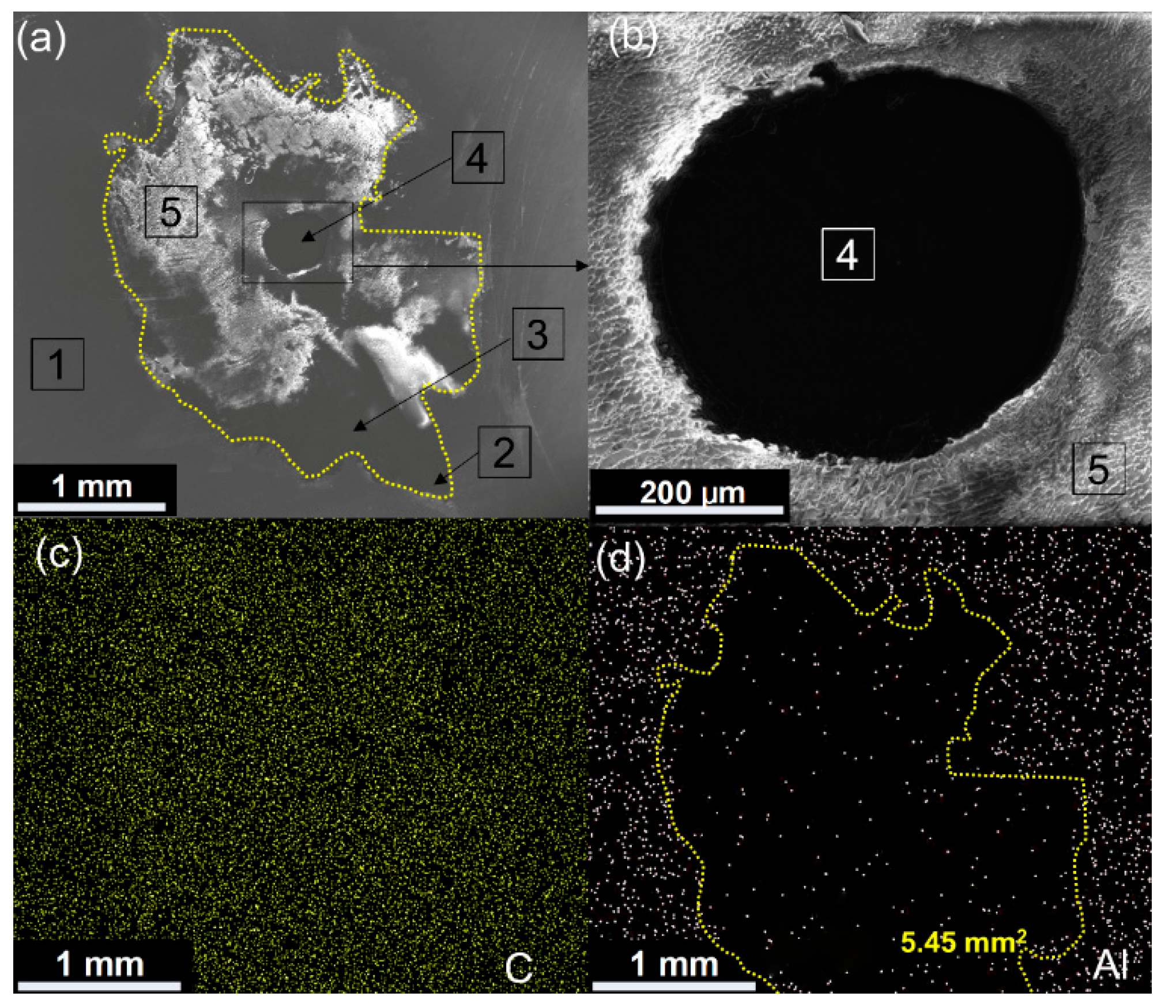
3.1. SH Electrochemical Behavior for Al Electrode and PP Dielectric

As shown in Figure 4a,b, we measured the microstructure morphology of the film surface in the self-healing area by SEM. This indicated that the Al electrode and PP dielectric in MPPFCs undergo electrochemical behavior during SH, altering their morphologies and forming a volcanic crater with an area of 5.45 mm2. The diameter of the breakdown channel in the metallized film is approximately 450 μm. From the breakdown hole to the edge of the volcanic crater (marked by a yellow dashed line), there is a partially carbonized area (Region 3 in Figure 4a). Region 5 in Figure 4a shows the carbon deposit, indicating that during the SH arc process, approximately 4 mm2 of the dielectric film surface was slightly decomposed. Related studies indicate that the decomposed PP thickness ranges between 20 and 40 nm [31,32]. Furthermore, EDS analysis of the element distribution on the self-healing area surface was conducted. The results in Figure 4c,d show a lower relative content of Al in the SH area, while the C element content is higher compared to the non-self-healing area, indicating that the Al electrode was evaporated due to the joule heat from the discharge arc [15].
Additionally, as shown in Figure 5, AFM was used to measure the surface 3D topography of area both before and afterself-healing. It was found that the surface roughness RMS of the film increased after SH. This suggests that electrochemical behavior during SH affects surface roughness, causing the dielectric film to melt and decomposed. The composition of gaseous products are mainly H2, C2H2, CO, and graphite [31].

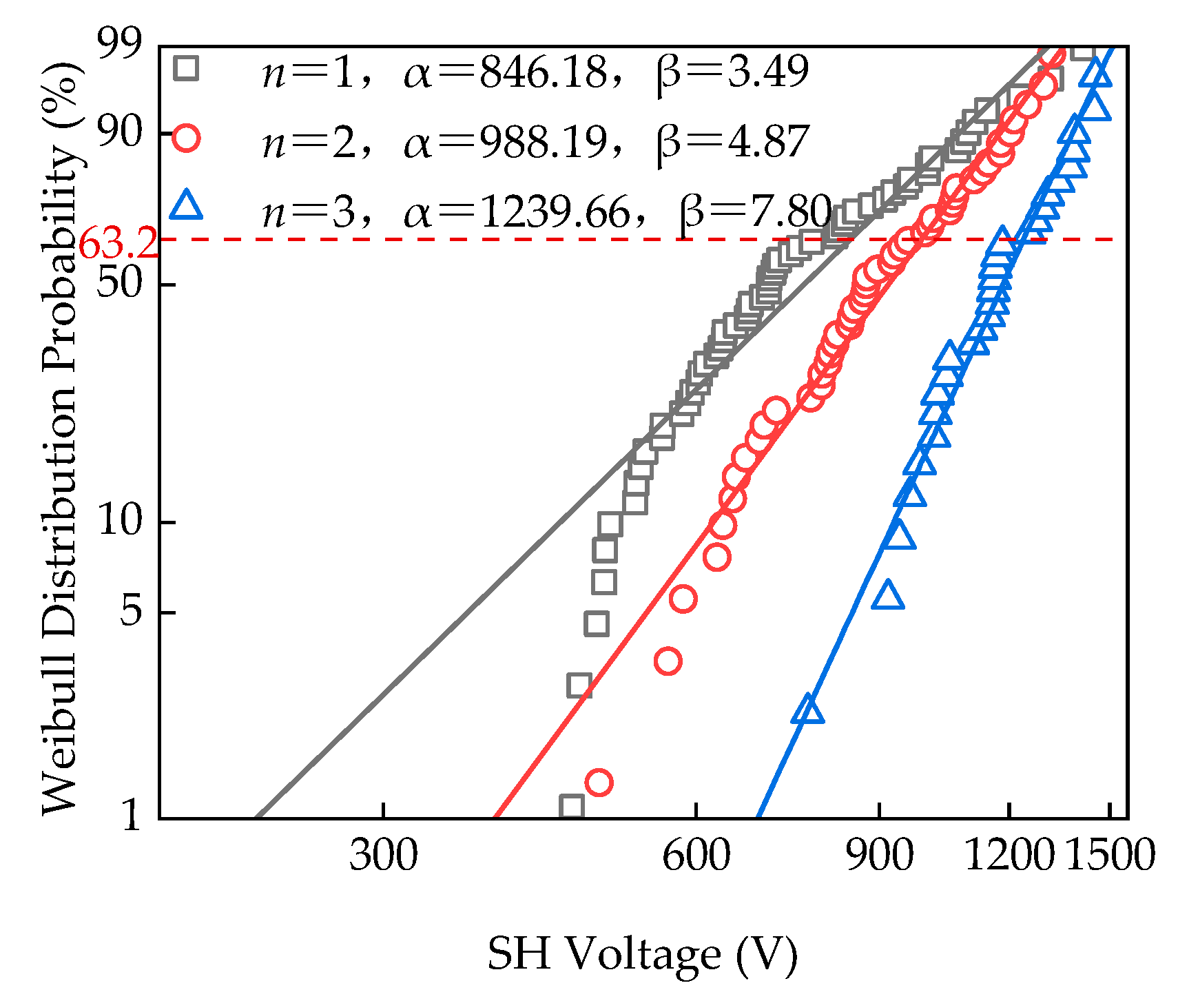
3.2. SH Voltage Distribution

For MPPFCs, self-healing is a localized breakdown phenomenon. The literature extensively uses the Weibull statistical distribution to characterize the self-healing breakdown performance of MPPFCs. In addition, the SH voltage follows an extreme value distribution, so a Weibull distribution is suitable for statistically assessing the probability of SH at different voltages. The Weibull probability equation is given as follows [33]:
F ( U s h ) = { 1 exp [ ( U sh α ) β ] , U s h 0   0 , U s h 0
where Ush is the SH voltage, F(Ush) is the SH probability, α is the scale parameter (voltage at 63.2% SH probability), and β is the shape parameter describing the slope of the distribution
For MPPFC undergoing SH, Figure 6 shows the Weibull distribution of SH voltages for different numbers of SH-breakdown film layers. The scale parameter α indicates that MPPFC has a 63.2% probability of SH at 846.18 V for a single-layer breakdown, 988.19 V for a two-layer breakdown, and 1239.66 V for a three-layer breakdown. This demonstrates a positive correlation between SH voltage and the number of SH-breakdown film layers.

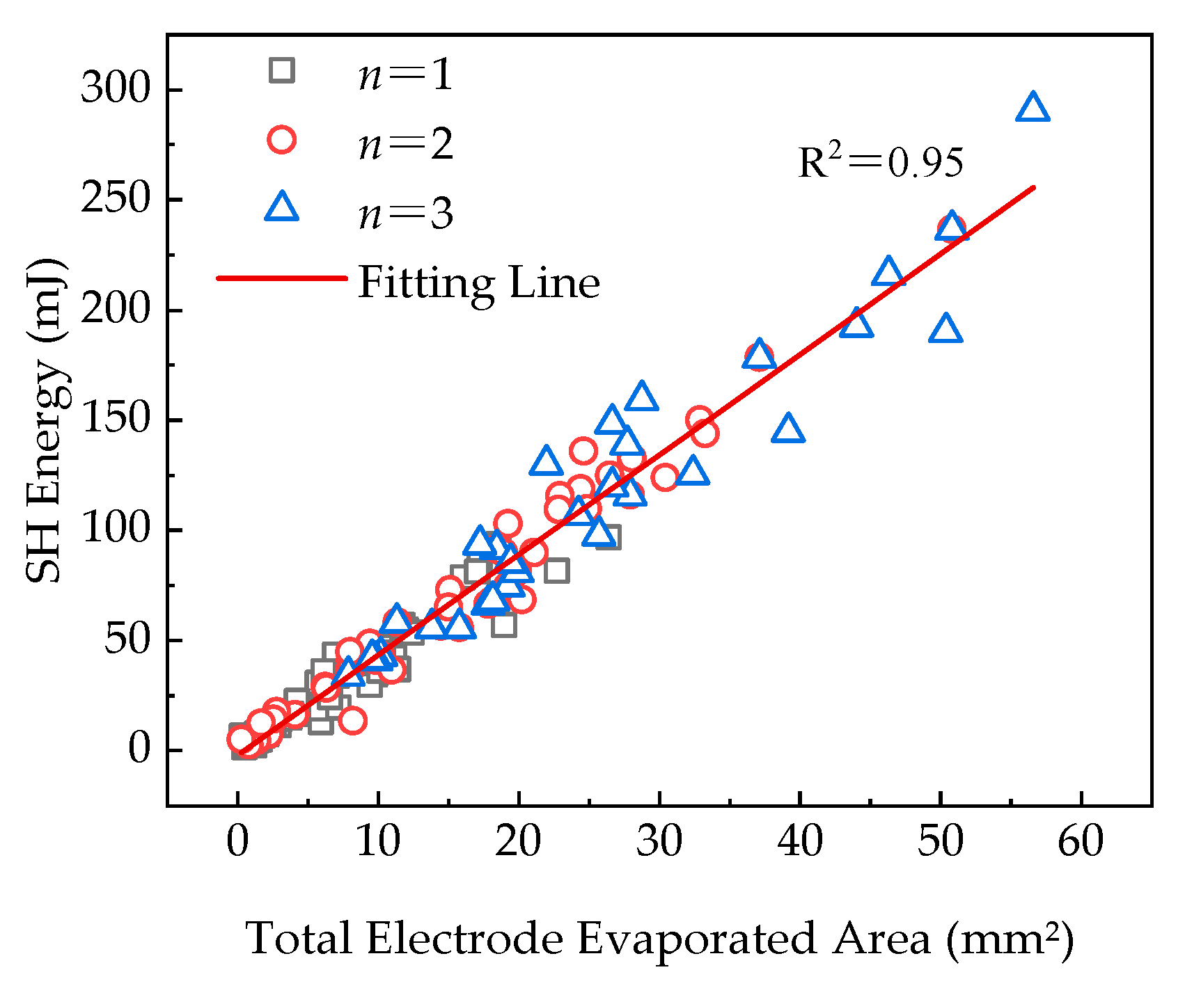
3.3. Correlation between Total Electrode Evaporated Area and SH Energy

Figure 7 depicts the relationship between the total electrode evaporated area and SH energy during a single SH event in MPPFC. The graph shows that as the total electrode evaporated area increases, SH energy also increases, following a linear relationship described as follows [34]:
W s h = a Σ S v + b
where a = 4.55 and b = −2.12. The coefficient a is related to the thermodynamic properties of aluminum [35].
For SH energy below 50 mJ, most samples experience a single-layer breakdown with an electrode evaporated area generally under 10 mm2. In the 50 mJ to 150 mJ range, two-layer breakdowns are more common. Beyond 150 mJ, three-layer breakdowns dominate. This probably occurs because maintaining a certain insulation distance between electrodes is necessary after dielectric breakdown to extinguish the discharge arc. As the number of SH breakdown film layers increases, each pair of electrodes requires a sufficient insulation distance to ensure successful SH in MPPFC, leading to larger evaporated areas and higher SH energy requirements [36]. However, it is also possible for high SH energy to occur even with a few breakdown layers. This is because SH energy is influenced by many factors, including interlayer pressure. Generally, when a single layer of the film breaks down with lower interlayer pressures, the SH energy is lower. However, if this SH occurs in the outer layer, the limited power to sustain the arc increases the arcing time, leading to higher SH energy [34].

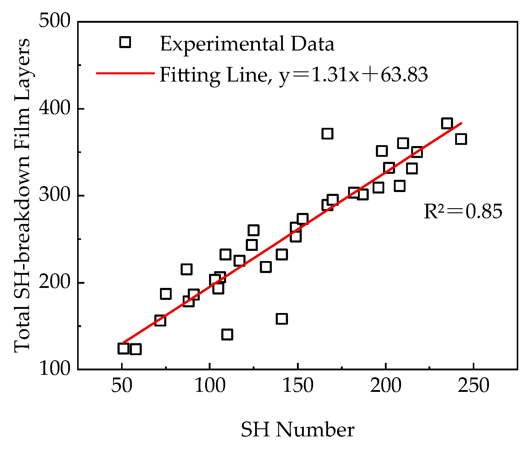
3.4. Cumulative SH Damage Feature Parameters Analysis

The experiments involved 10 consecutive voltage increase tests on 35 MPPFC samples. Figure 8, Figure 9 and Figure 10 show the relationships between the SH number (k), the total SH-breakdown film layers (n), the average number of broken-down film layers per SH event, and the average single SH energy. Figure 8 shows a positive correlation between the SH number and the total SH-breakdown film layers. The R2 value of 0.85 suggests that this relationship is not entirely linear. The average number of broken-down film layers per SH event, shown in Figure 9, is calculated by dividing the total SH-breakdown film layers by the number of SH events. The average ranges from one to three layers. When the SH number is below 100, the average exceeds two layers. Beyond 100 SH events, the average drops to between one and two layers, indicating an increasing likelihood of single-layer SH events. Despite this trend, some instances involve two or three layers even after 100 SH events, as shown by the outliers in Figure 9.
Figure 10 illustrates the relationship between SH number and average single SH energy. As the SH number increases, the average single SH energy generally decreases. This may be due to the accumulation of conductive graphite particles, which reduces insulation and increases the likelihood of SH events. The decrease in average single SH energy is consistent with the finding that SH events typically break down only one layer, which requires less energy.

3.5. Capacitance Loss Analysis under Single SH

SH causes irreversible damage to the PP dielectric and Al electrode of MPPFC, leading to capacitance loss due to a reduction in the effective electrode area (ΔS). The capacitance loss (Closs) is directly proportional to ΔS [7]:
C l o s s = ε 0 ε r Δ S d
where ε0 is 8.85 × 10⁻¹² F/m; εr for the PP dielectric is 2.2; and d (thickness of a single dielectric layer) is 5 μm.
Given the wound structure of MPPFC, the total electrode evaporated area (ΣSv) differs from ΔS. The reduction in the effective electrode area for each thin film layer is determined by the layer with the largest evaporated area above and below each PP layer. The reduction in effective electrode area (ΔS) can be calculated by summing the maximum evaporated areas (Smax) for each layer.
In Figure 3b, the film layers with reduced electrode effective areas are identified as layers II, III, and IV. Layers II and III correspond to a reduced electrode effective area of S1, while layer IV has a reduced electrode effective area of S2. These values need to be summed to obtain the overall reduction in effective electrode area ΔS. S1 represents the maximum evaporated area Smax of a single layer electrode during a single SH event, which is also the difference between the reduced effective electrode area when SH breaks down a single film layer and the total electrode evaporated area ΣSv. Similar analysis can be applied for the SH breakdown of two or three film layers, yielding the relationship between the reduced effective electrode area and the total electrode evaporated area, which is expressed as follows:
Δ S = S max + Σ S v .
Figure 11 shows the statistical proportion of the maximum evaporated area of a single layer electrode Smax during a single SH event within the total electrode evaporated area ΣSv. As the number of breakdown layers in a single SH event increases from one to three, the proportion kn, which divides Smax by ΣSv, gradually decreases. This indicates that the relationship between the reduced effective electrode area and the total electrode evaporated area follows a nonlinear trend, which is expressed as follows:
Δ S = ( 1 + k n ) Σ S v , k n = { k 1 = 0.628 , n = 1 k 2 = 0.602 , n = 2 k 3 = 0.554 , n = 3
where kn represents the mean coefficient of proportion and k1, k2, and k3 represent the mean proportions of Smax within ΣSv when the number of layers self-healed in a single SH event are one, two, and three layers, respectively.
Combining equation (6) with (8) to obtain (9) can be used to calculate the capacitance loss caused by a single SH event. From Equation (9), capacitance loss has a nonlinear relationship with the total electrode evaporation area. When the SH breakdown layer number n is different, the mean coefficient of proportion kn will change accordingly. Therefore, the capacitance loss is determined by both the SH-breakdown layer number n and the electrode’s total evaporation area ΣSv.
C l o s s = ε 0 ε r ( 1 + k n ) Σ S v d

3.6. Capacitance Evaluation Method under Cumulative SH

Due to the inherent variability in the initial capacitance values of the samples, estimating the changes in capacitance during cumulative SH requires a systematic approach. First, the initial capacitance value C0, was measured using an LCR meter. This initial value was then utilized in conjunction with Equation (9) to calculate the capacitance during the cumulative SH process, as follows:
C = C 0 ε 0 ε r j = 1 k [ ( 1 + k n , j ) Σ S v , j ] d
where k represents the SH number and kn,j and ΣSv,j represent the proportion of the maximum electrode evaporation area and the total electrode evaporation area when the jth SH event occurs with n layers of film breakdown.
In practice, determining the total electrode evaporation area requires disassembling MPPFCs, which can be challenging. On the other hand, SH energy is a macroscopic characteristic parameter that is relatively easy to obtain, and it exhibits a linear relationship with capacitance, as indicated by Equation (5). This leads to the formulation of the capacitance calculation equation, as follows:
C = C 0 ε 0 ε r j = 1 k [ ( 1 + k n , j ) ( W s h , j b ) ] a d
where Wsh,j represents the SH energy of the jth SH event and parameters a and b are coefficients, which could be obtained from Equation (5).
Therefore, when calculating the cumulative capacitance under SH conditions, it is crucial to obtain SH-breakdown film layers during each SH event and their corresponding SH energy, which can then be solved using Equation (11). Consequently, acquiring SH-breakdown film layers during each SH event is of paramount importance. However, in practical scenarios, it is often not feasible to dismantle SH samples after every event to obtain this parameter; therefore, an effective parameter evaluation method is required.
With the results of the correlation analysis of characteristic parameters discussed earlier, the SH voltage and SH energy can serve as classification feature parameters. These parameters were used in conjunction with SH-breakdown film layers of each SH event as the classification label. A classification model was trained using SH samples with known classifications. Subsequently, for any given sample, the SH voltage and SH energy were extracted during each SH event, and the corresponding electrode’s total evaporation area was computed. The classification model was then used to evaluate SH-breakdown film layers during each SH event, which were subsequently employed in the formula to estimate the change in capacitance.
According to the distribution of SH voltage and SH energy, as depicted in Figure 12 (The "+" like lines represent the arithmetic mean and error bars for SH breakdown at one, two, and three layers of the film for Ush and Wsh, where half the length of the error bar represents the standard deviation.), different film breakdown layers can correspond to the same SH energy and some data slightly overlap; thus, for the case where the actual number of SH-breakdown film layers is unknown, there exists part of the SH samples, and it is hard to categorize and evaluate the number of SH-breakdown film layers directly by the distribution law of SH voltage and SH energy.
To obtain better separability, the feature dimension can be increased by transforming vectors (Ush, Wsh) to a higher dimensional feature space using a certain function Φ, so as to find the appropriate classification boundaries according to the SVM algorithm in higher dimensions. In this paper, the most commonly used Gaussian kernel function [37,38], κ(x, xi) = exp[−(xxi)2/(2σ2)] was adopted to map the low-dimensional feature vectors to a vector space of higher dimensions, so as to realize the classification of the number of SH-breakdown film layers and to construct a classification model.
This study utilized a feature parameter set comprising 136 groups. The dataset was divided into training and testing sets, with 90 groups (66% of the dataset) for training and 46 groups for test (34% of the dataset). An SVM algorithm was employed to construct the classification model, and the model predicted accuracy of the training sample and test sample was 84.6% and 82.6%, respectively, as shown in Figure 13 (The black symbols represent the actual experimental results of SH-breakdown film layers, while the red symbols indicate the predictions of the SVM model). Combining the above analyses, the flowchart of the capacitance evaluation method is illustrated in Figure 14.
As depicted in Figure 15, the SH voltage data of each SH moment and the SH energy during the self-healing process were input into the trained classification model, the number of film SH-breakdown layers during every SH was evaluated, and the lost capacitance and accumulated SH energy were output with Equation (11). Since SH occurs in a localized area of the capacitor for a very short time (μs degree), it has less effect on the performance of the material in the non-self-healing region. It mainly results in capacitance loss of the capacitor component. Additionally, SH in capacitors is typically random. Even at the same SH voltage Ush, the SH energy Wsh can vary. This results in different values of voltage loss and voltage fluctuations, as shown in Figure 15. This variation may be because the SH energy depends on the SH location. The inner layers of MPPFCs, with lower interlayer pressures, require less SH energy compared to the outer layers. When interlayer pressures increase, the SH arc to maintain combustion requires a higher power density of energy injection, so the arc is easy to extinguish, and the SH energy decreases [34].
Then, the description provided discusses the results of 10 consecutive voltage increase tests conducted on three samples under the same conditions. These tests were performed to compare and validate the capacitance evaluation method. Figure 16 illustrates the changes in accumulated capacitance and relative error under cumulative SH conditions. In Figure 16, the estimated values were obtained using the capacitance evaluation method, while the measured values were determined by measuring the capacitance C at the end of each voltage increase test using a LCR meter.
The data from Figure 16 show that the measured capacitance decreases as the cumulative SH energy increases. This decrease is primarily due to the fact that with higher cumulative SH energy, there are more SH events, resulting in a larger reduction in effective electrode area and, consequently, more significant capacitance loss [39]. Although the goodness of fit in the estimated capacitance values to the measured vales is around 0.6~0.7, which is possibly the reason for lackless measurement accuracy, this still demonstrates the effectiveness of the proposed method and its ability to accurately estimate the capacitance under cumulative SH conditions.

4. Conclusions

This study presents a capacitance evaluation method for MPPFCs based on their SH damage feature parameters. The main findings and conclusions are outlined as follows:
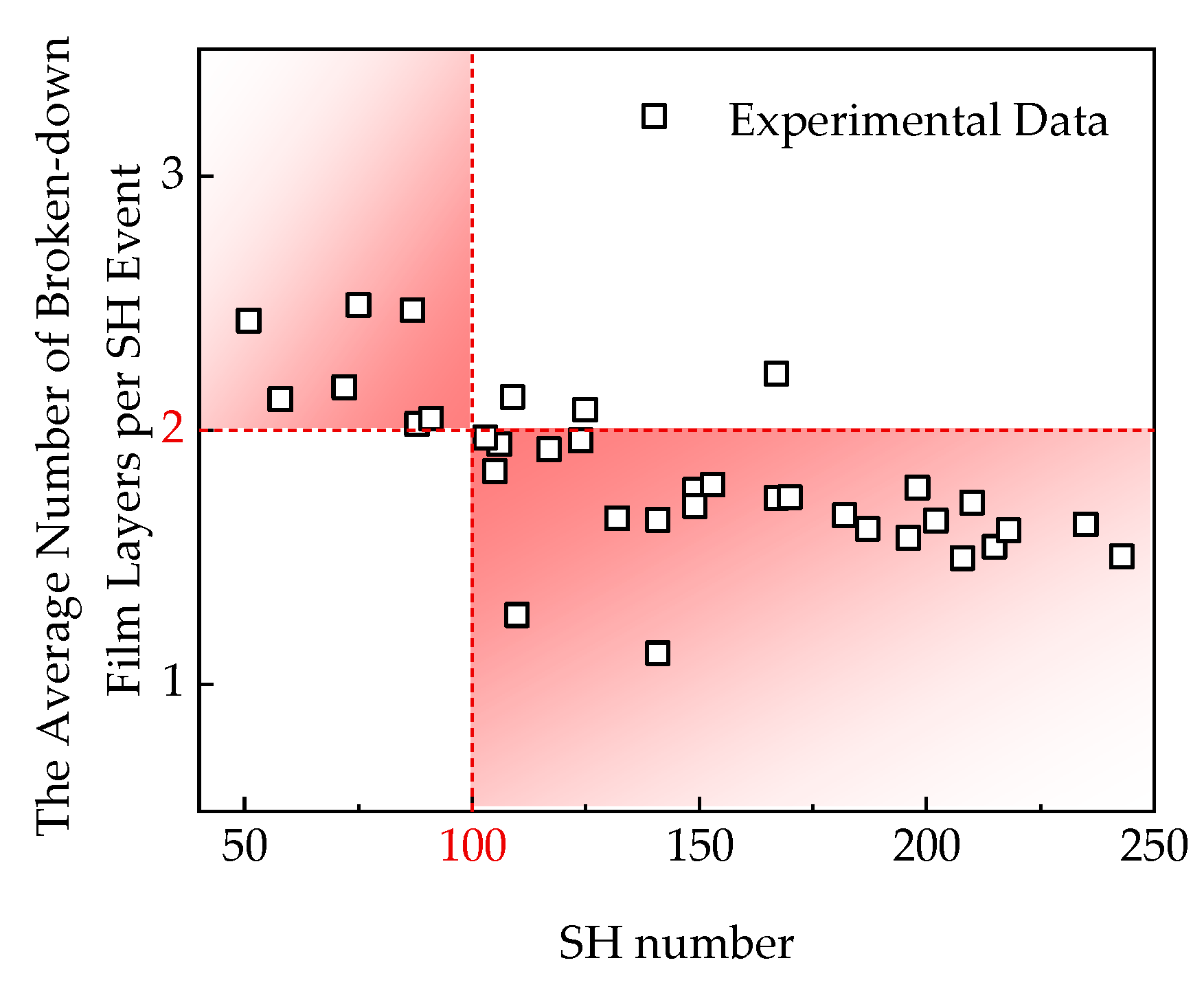
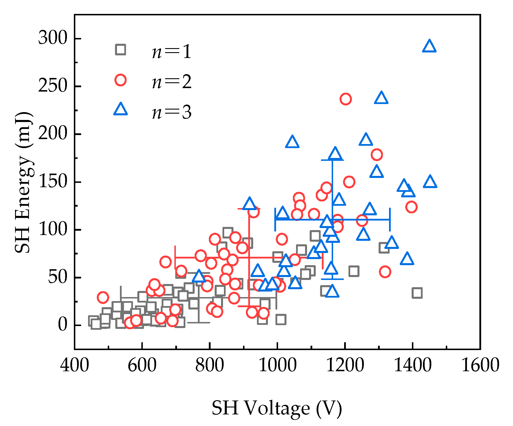
  • The Al electrode and PP dielectric in an MPPFC undergo electrochemical behavior during SH, altering their morphologies—the Al electrode is cleared and the PP dielectric is decomposed. As the SH voltage increases, the number of SH-breakdown film layers during a single SH event rises, leading to a significant increase in SH energy. The electrode also incurs losses due to high-temperature evaporation. Under cumulative SH conditions, there is a positive correlation between the SH number and the total number of SH-breakdown film layers, and the linear regression model has a slope close to 1. The average single SH energy decreases exponentially with SH number. As the SH number increases, the probability of SH breaking only one layer of film in each event rises;
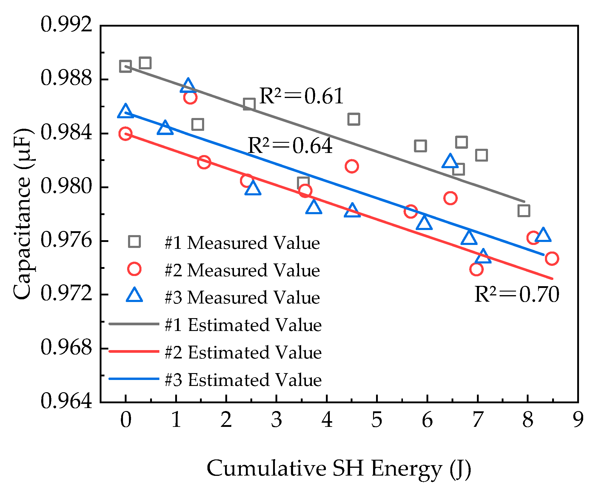
  • Capacitance loss calculations need to account for the winding structure of the capacitor. It was observed that capacitance loss is nonlinearly related to the total electrode evaporation area. Under single SH conditions, capacitance loss is determined by both the SH-breakdown film layers and the electrode evaporation area. Therefore, an improved equation for capacitance loss calculation was proposed;
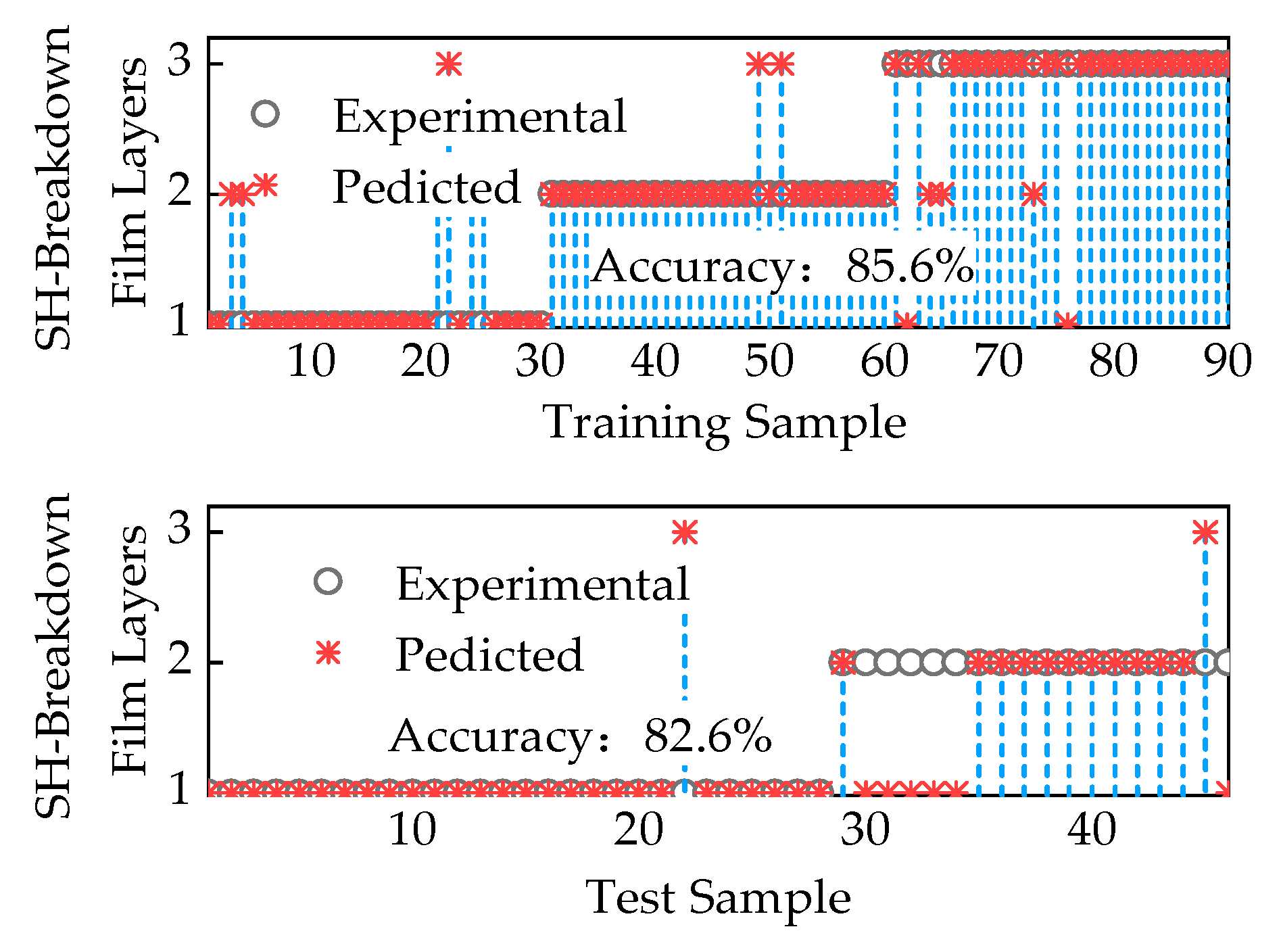
  • Based on the distribution patterns of SH voltage and SH energy for different numbers of SH-breakdown film layers during SH, it was found that these characteristic parameters can be used to construct a feature parameter set. Thus, this study employed the SVM algorithm to classify the feature parameter set and identify the SH-breakdown film layers and the total electrode evaporation area during each SH event, and the model classification accuracy was 82.6%. A capacitance evaluation method for cumulative SH in MPPFC was proposed. Comparative analysis with measured data indicates the effectiveness of the evaluation method.
Our current data come from the MPPFC self-healing test simulation platform, where the capacitance evaluation method described in this article has been shown to have applicability. In the future, the evaluation of capacitance after SH of MPPFCs with real-world data from operational environments, such as at higher temperatures and voltage rates, will be considered. We will further analyze the SH mechanism of MPPFCs to reveal the changes in capacitor performance during service.

Author Contributions

Conceptualization, J.Z.; methodology, G.D.; software, G.D.; validation, J.Z.; formal analysis, G.D; investigation, G.D.; resources, J.Z.; data curation, J.Z.; writing—original draft preparation, G.D.; writing—review and editing, G.D.; visualization, G.D.; supervision, G.D.; funding acquisition, G.D. All authors have read and agreed to the published version of the manuscript.

Funding

This work was supported by the National Natural Science Foundation of China (92166206).

Data Availability Statement

The raw data supporting the conclusions of this article will be made available by the authors on request.

Conflicts of Interest

The authors declare that they have no known competing financial interests or personal relationships that could have appeared to influence the work reported in this paper.

References

  1. Lei, W.; Liu, J.; Lv, G.; Cao, R. Review of Reliability Comprehensive Analysis and Evaluation Methods for Key Components and System of Large Capacity Power Electronic Equipment. High Volt. Eng. 2020, 46, 3353–3361. [Google Scholar] [CrossRef]
  2. Li, Q.; Li, M. High-temperature Polymer Dielectrics for Film Capacitors: Review and Prospect. High Volt. Eng. 2021, 47, 3105–3123. [Google Scholar] [CrossRef]
  3. Du, B.; Ran, Z.; Liu, H.; Xiao, M. Research Progress of Dielectric Properties and Improvement Methods of Polypropylene Film for Dry-Type Capacitor. Trans. China Electrotech. Soc. 2023, 38, 1363–1374. [Google Scholar] [CrossRef]
  4. Tai, Y.; Chen, P.; Jian, Y.; Fang, Q.; Xu, D.; Cheng, J. Failure Mechanism and Life Estimate of Metallized Film Capacitor under High Temperature and Humidity. Microelectron. Reliab. 2022, 137, 114755. [Google Scholar] [CrossRef]
  5. Zhang, J.; Yu, C.; Pan, L.; Du, Y.; Zhu, L. Study on Aging Mechanism of Metallized Film Capacitor Based on Surface Analysis. Guangdong Electr. Power 2019, 32, 119–125. Available online: https://kns.cnki.net/kcms/detail/44.1420.TM.20190827.1428.030.html (accessed on 9 July 2024).
  6. Xu, Z.; Cheng, L.; Liu, H.; Wang, J.; Ma, Y.; Li, Z.; Liu, W.; Guo, J. Ageing characteristics of metallized film capacitor under ultra-high DC field. Insul. Mater. 2023, 56, 55–62. [Google Scholar] [CrossRef]
  7. Sarjeant, W.J.; Zirnheld, J.; MacDougall, F.W. Capacitors. IEEE Trans. Plasma Sci. 1998, 26, 1368–1392. [Google Scholar] [CrossRef]
  8. Picci, G.; Rabuffi, M. Status Quo and Future Prospects for Metallized Polypropylene Energy Storage Capacitors. In Proceedings of the IEEE Conference Record—Abstracts. PPPS-2001 Pulsed Power Plasma Science 2001. 28th IEEE International Conference on Plasma Science and 13th IEEE International Pulsed Power Conference (Cat. No.01CH37255), Las Vegas, NV, USA, 17–22 June 2001; p. 374. [Google Scholar]
  9. Zhu, J.; Tong, H.; Cao, S.; Liu, J.; Peng, W. Study on self-healing properties of metallized high-temperature dielectric films for capacitors. Adv. Technol. Electr. Eng. Energy 2024, 43, 1–13. [Google Scholar] [CrossRef]
  10. Ho, J.S.; Greenbaum, S.G. Polymer Capacitor Dielectrics for High Temperature Applications. ACS Appl. Mater. Interfaces 2018, 10, 29189–29218. [Google Scholar] [CrossRef]
  11. Huan, T.D.; Boggs, S.; Teyssedre, G.; Laurent, C.; Cakmak, M.; Kumar, S.; Ramprasad, R. Advanced Polymeric Dielectrics for High Energy Density Applications. Prog. Mater. Sci. 2016, 83, 236–269. [Google Scholar] [CrossRef]
  12. Tan, D.Q.; Wu, X. A Case Study of High-Temperature Polyetherimide Film Capacitor Fabrication. Mater. Today Energy 2022, 30, 101167. [Google Scholar] [CrossRef]
  13. Ma, Y.; Shen, H.; Pei, C.; Zhang, H.; Junaid, M.; Wang, Y. Detection of Self-Healing Discharge in Metallized Film Capacitors Using an Ultrasonic Method. Electronics 2020, 9, 1893. [Google Scholar] [CrossRef]
  14. Belko, V.; Glivenko, D.; Emelyanov, O.; Ivanov, I.; Plotnikov, A. Current Pulse Polarity Effect on Metallized Film Capacitors Failure. IEEE Trans. Plasma Sci. 2017, 45, 1020–1025. [Google Scholar] [CrossRef]
  15. Li, H.; Wang, B.; Li, Z.; Liu, D.; Li, H.; Zhang, Q.; Lin, F.; Chen, Y. Effect of Pulsed Discharge Current on Lifetime Performance of Metallized Polypropylene Film Capacitors. IEEE Trans. Dielectr. Electr. Insul. 2014, 21, 957–963. [Google Scholar] [CrossRef]
  16. Li, Z.; Wang, J.; Xu, Z.; Wang, X.; Cheng, L.; Liu, W. Self-healing Characteristics and Life Prediction of Metallized Film Capacitor under DC Voltage. High Volt. Eng. 2023, 49, 2929–2937. [Google Scholar] [CrossRef]
  17. Sarjeant, W.J.; MacDougall, F.W.; Larson, D.W.; Kohlberg, I. Energy Storage Capacitors: Aging, and Diagnostic Approaches for Life Validation. IEEE Trans. Magn. 1997, 33, 501–506. [Google Scholar] [CrossRef]
  18. Lv, C.; Liu, J.; Zhang, Y.; Lei, W.; Cao, R. An Improved Lifetime Prediction Method for Metallized Film Capacitor Considering Harmonics and Degradation Process. Microelectron. Reliab. 2020, 114, 113892. [Google Scholar] [CrossRef]
  19. He, Y.; Su, Q.; Liu, D.; Xia, L.; Huang, X.; Lan, D.; Liu, Y.; Huang, Y.; Zhong, B. Surface Engineering Strategy for MXene to Tailor Electromagnetic Wave Absorption Performance. Chem. Eng. J. 2024, 491, 152041. [Google Scholar] [CrossRef]
  20. Belko, V.O.; Emelyanov, O.A.; Ivanov, I.O.; Plotnikov, A.P. Self-Healing Processes of Metallized Film Capacitors in Overload Modes-Part 1: Experimental Observations. IEEE Trans. Plasma Sci. 2021, 49, 1580–1587. [Google Scholar] [CrossRef]
  21. Hu, Y.; Ye, X.; Zheng, B.; Zhao, Z.; Zhai, G. Degradation Mechanisms-Based Reliability Modeling for Metallized Film Capacitors under Temperature and Voltage Stresses. Microelectron. Reliab. 2022, 138, 114609. [Google Scholar] [CrossRef]
  22. Li, Z.; Sun, B.; He, D.P. Fault Analysis and Improvement Measure for 10 kV Dry Type Self-healing Capacitor. High Volt. Eng. 2005, 82–83, 82–83. [Google Scholar] [CrossRef]
  23. Tan, D.; Wang, Q.; Li, M.; Song, L.; Zhang, F.; Min, Z.; Wang, H.; Zhu, Y.; Zhang, R.; Lan, D.; et al. Magnetic Media Synergistic Carbon fiber@Ni/NiO Composites for High-Efficiency Electromagnetic Wave Absorption. Chem. Eng. J. 2024, 492, 152245. [Google Scholar] [CrossRef]
  24. Yang, X.; Xuan, L.; Men, W.; Wu, X.; Lan, D.; Shi, Y.; Jia, H.; Duan, Y. Carbonyl Iron/Glass Fiber Cloth Composites: Achieving Multi-Spectrum Stealth in a Wide Temperature Range. Chem. Eng. J. 2024, 491, 151862. [Google Scholar] [CrossRef]
  25. Dai, X.; Lin, F.; Li, J.; Yao, Z.; Wang, N. Influence Factors for the Self-Healing of Metallized Polypropylene Capacitors. In Proceedings of the 2000 Annual Report Conference on Electrical Insulation and Dielectric Phenomena (Cat. No.00CH37132), Victoria, BC, Canada, 15–18 October 2000; Volume 2, pp. 461–465. [Google Scholar] [CrossRef]
  26. Zhang, G.; Li, H.; Lan, J.; Li, H.; Li, Z.; Lin, F.; Zhang, Q. Study on the Dynamic Process and Extinguishing Criterion of Metallized Film Self-Healing Arc. In Proceedings of the 2023 IEEE Electrical Insulation Conference (EIC), Quebec City, QC, Canada, 18–21 June 2023; pp. 1–4. [Google Scholar]
  27. Bel’ko, V.O.; Bondarenko, P.N.; Emel’yanov, O.A. The Dynamic Characteristics of Self-Healing Processes in Metal Film Capacitors. Russ. Electr. Eng. 2007, 78, 138–142. [Google Scholar] [CrossRef]
  28. Cheng, L.; Li, Z.; Wang, J.; Liu, W.; Li, S. Mechanism Study on the Failure of Metalized Film Capacitor Under HVDC Field Superimposed Harmonics. Proc. CSEE. 2023, 43, 8955–8965. [Google Scholar] [CrossRef]
  29. Makdessi, M.; Sari, A.; Venet, P. Metallized Polymer Film Capacitors Ageing Law Based on Capacitance Degradation. Microelectron. Reliab. 2014, 54, 1823–1827. [Google Scholar] [CrossRef]
  30. He, Y.; Wang, F.; Du, G.; Pan, L.; Wang, K.; Kong, D.; Zhang, X. From Independent to Related: Voltage Ramp Rate Effects on Self-Healing Scaling in Metallized Polypropylene Film Capacitors. IEEE Trans. Dielectr. Electr. Insul. 2023, 30, 2189–2198. [Google Scholar] [CrossRef]
  31. Kammermaier, J.; Rittmayer, G.; Birkle, S. Modeling of Plasma-Induced Self-Healing in Organic Dielectrics. J. Appl. Phys. 1989, 66, 1594–1609. [Google Scholar] [CrossRef]
  32. Kammermaier, J. Chemical Prpcesses During Electrical Breakdown in an Organic Dielectric with Evaporated Thin Electrodes. IEEE Trans. Electr. Insul. 1987, EI-22, 145–149. [Google Scholar] [CrossRef]
  33. Hauschild, W.; Mosch, W. Statistical Techniques for High-Voltage Engineering; IET Digital Library: London, UK, 1992; ISBN 978-1-84919-429-7. [Google Scholar]
  34. Li, H.; Zhang, M.; Lin, F.; Cheng, Y.; Lv, F.; Li, Z.; Peng, B. Study on Theory and Influence Factors of Self-Healing in Metallized Film Capacitors. Trans. China Electrotech. Soc. 2012, 27, 218–223+230. [Google Scholar] [CrossRef]
  35. Tortai, J.H.; Denat, A.; Bonifaci, N. Self-Healing of Capacitors with Metallized Film Technology: Experimental Observations and Theoretical Model. J. Electrost. 2001, 53, 159–169. [Google Scholar] [CrossRef]
  36. Pan, L.; Wang, F.; He, Y.; Sun, X.; Du, G.; Zhou, Q.; Zhang, J.; Zhang, Z.; Li, J. Reassessing Self-Healing in Metallized Film Capacitors: A Focus on Safety and Damage Analysis. IEEE Trans. Dielectr. Electr. Insul. 2024. [Google Scholar] [CrossRef]
  37. Li, C.; Wang, B. A Knowledge Graph Method towards Power System Fault Diagnosis and Classification. Electronics 2023, 12, 4808. [Google Scholar] [CrossRef]
  38. Lin, S.-L. Application of Machine Learning to a Medium Gaussian Support Vector Machine in the Diagnosis of Motor Bearing Faults. Electronics 2021, 10, 2266. [Google Scholar] [CrossRef]
  39. Haripriya, M.; Manimekala, T.; Dharmalingam, G.; Minakshi, M.; Sivasubramanian, R. Asymmetric Supercapacitors Based on ZnCo2O4 Nanohexagons and Orange Peel Derived Activated Carbon Electrodes. Chem. Asian J. 2024, 19, e202400202. [Google Scholar] [CrossRef] [PubMed]
Figure 1. MPPFC sample physical and structural schematic 1: PP dielectric; 2: Al electrode; 3: Mandrel; 4: Clear edge; and 5: Schoopage.
Electronics 13 02886 g001
Figure 2. SH test circuit.
Electronics 13 02886 g002
Figure 3. Film damage around SH points: (a) Optical microscope image of SH breakdown in a single film layer (red dashed circle highlights the SH damage area; red numerals represent the surface layer sequence). (b) Schematic side view of SH breakdown in a single film layer (Roman numerals indicate the film layer sequence). (c) Optical microscope image of SH breakdown in two film layers. (d) Schematic side view of SH breakdown in two film layers. (e) Optical microscope image of SH breakdown in three film layers. (f) Schematic side view of SH breakdown in three film layers.
Electronics 13 02886 g003aElectronics 13 02886 g003b
Figure 4. (a,b) Surface morphology of metallized film after SH breakdown 1: edge of the safe aluminum electrode around the crater; 2: roll of melted aluminum around the crater; 3: carbonized PP film surface; 4: the main breakdown channel; and 5: PP ablation zone. (c,d) EDS mapping of C and Al.
Electronics 13 02886 g004
Figure 5. (a,b) Surface morphology of metallized film by AFM: (a) Before SH. (b) After SH.
Electronics 13 02886 g005
Figure 6. Weibull distribution of SH voltage.
Electronics 13 02886 g006
Figure 7. Relationship curve between total electrode evaporation area and SH energy.
Electronics 13 02886 g007
Figure 8. Relationship curve between SH number and total SH-breakdown film layers.
Electronics 13 02886 g008
Figure 9. Relationship curve between SH number and the average number of broken-down film layers of each SH event.
Electronics 13 02886 g009
Figure 10. Relationship curve between SH number and average single SH energy.
Electronics 13 02886 g010
Figure 11. The statistical proportion of the maximum evaporated area of a single layer electrode.
Electronics 13 02886 g011
Figure 12. Distribution of SH voltage and SH energy.
Electronics 13 02886 g012
Figure 13. The result of SH-breakdown film layer classification.
Electronics 13 02886 g013
Figure 14. Capacitance evaluation method flowchart.
Electronics 13 02886 g014
Figure 15. Example of consecutive SH breakdowns measured on a capacitor.
Electronics 13 02886 g015
Figure 16. Changes in capacitance under cumulative SH.
Electronics 13 02886 g016
Table 1. General characteristics of the most diffused dielectric films.
Plastic FilmεMaximum
Operating
Temperature [°C]
Breakdown Filed [V·μm−1]Dissipation Factor %
1 kHz
Energy
Density [J·cm−3]
References
Biaxially oriented polypropylene2.2~2.25105640~764≤0.021~1.2[8,9,10,11]
Polyester3.2~3.3125570<0.51~1.5[8,10,11]
Polycarbonate2.8~2.9125528<0.150.5~1[8,10,11]
Polyvinylidene
fluoride
12125590<1.82.4[8]
Polyethylene
naphlate
3~3.2125500~559<0.151~1.5[8,9,10,11,12]
Polyphenylene-sulfide (PPS)3200550<0.031~1.5[8,10,11]
Ether ether ketone (PEEK)2.97/4460.25/[9,10,12]
Table 2. SH area statistical.
Total Dielectric Thermal Damage Area/mm²Total Electrode Evaporation Area/mm²
SH Breakdown in Single-Film Layer7.224.42
SH Breakdown in Two-Film Layer57.1339.65
SH Breakdown in Three-Film Layer63.4844.49
Disclaimer/Publisher’s Note: The statements, opinions and data contained in all publications are solely those of the individual author(s) and contributor(s) and not of MDPI and/or the editor(s). MDPI and/or the editor(s) disclaim responsibility for any injury to people or property resulting from any ideas, methods, instructions or products referred to in the content.

