Article

Decentralized Retrofit Model Predictive Control of Inverter-Interfaced Small-Scale Microgrids

1
Department of Electrical and Computer Engineering, New Jersey Institute of Technology, Newark, NJ 07102, USA
2
School of Applied Engineering and Technology, New Jersey Institute of Technology, Newark, NJ 07102, USA
*
Author to whom correspondence should be addressed.
Electronics 2024, 13(15), 2914; https://doi.org/10.3390/electronics13152914
Submission received: 5 June 2024 / Revised: 9 July 2024 / Accepted: 17 July 2024 / Published: 24 July 2024
(This article belongs to the Special Issue Advances in Enhancing Energy and Power System Stability and Control)

Abstract

:
In recent years, small-scale microgrids have become popular in the power system industry because they provide an efficient electrical power generation platform to guarantee autonomy and independence from the power grid, which is a critical feature in cases of catastrophic events or remote areas. On the other hand, due to the short distances among multiple distribution generation systems in small-scale microgrids, the interconnection couplings among them increase significantly, which jeopardizes the stability of the entire system. Therefore, this work proposes a novel method to design decentralized robust controllers based on a retrofit model predictive control scheme to tackle the issue of instability due to the short distances among generation systems. In this approach, the retrofit model predictive controller receives the measured feedback signal from the interconnection current and generates a control command signal to limit the interconnection current to prevent instability. To design a retrofit controller, only the model of a robust closed-loop system, as well as an interconnection line, is required. The model predictive control signal is added in parallel to the control signal from the existing robust voltage source inverter controller. Simulation results demonstrate the superior performance of the proposed technique as compared with the virtual impedance and retrofit linear quadratic regulator techniques (benchmarks) with respect to peak-load demand, plug-and-play capability, nonlinear load, and inverter efficiency.

1. Introduction

1.1. Motivation

The currently used power system infrastructures are suffering from a number of difficulties due to the usage of long-distance transmission lines that deliver electrical power from central generation systems to consumers [1]. This leads to extensive line losses and low grid efficiency [2]. This method of power transmission can cause costly power outages due to environmental (wind or heavy rain) and non-environmental (equipment failure) factors [3]. Moreover, the large power generators used in central power plants utilize fossil fuels, which contribute to the release of 36.6 billion tons of carbon dioxide into the atmosphere each year [4]. In addition to environmental issues, according to [5], 768 million people are estimated to not have access to electricity, most of whom live in rural or remote regions, where expanding the grid transmission lines is often deemed uneconomical [6].
One powerful solution to address the above-mentioned problems is to generate electricity from renewable energy resources by using photovoltaic (PV) panels and wind turbines, which are referred to as distributed energy resources (DERs). Such DERs can generate electrical power in close proximity to consumers, eliminating the need to build long transmission lines. These DERs can be grouped together with short distances between them to form a small-scale microgrid (SSMG). Despite their considerable contributions to the growth of energy resources and a cleaner environment, DERs bring about new challenges as a result of their intermittent behavior [7]. Moreover, replacing conventional synchronous generators with DERs reduces the inertia of the entire system, which, in turn, jeopardizes the system’s stability [8].
One major problem in such SSMGs is the elevated interconnection coupling strength due to the short distances among DERs. We introduced this issue in [9] for a generation system comprising two inverters with inductor–capacitor filters (LC filters), which are connected to one another through series resistive and inductive interconnection lines. It is shown that by decreasing the distance between the two inverters, the impedance between them decreases as well, which, in turn, increases the norm of the interconnection line transfer function. This is associated with an increase in interconnection coupling strength between the two inverters, which jeopardizes the stability of the entire system if conventional decentralized controllers are used. In such conventional ones, where the controllers are designed independently, the impact of the interconnection line is considered an external disturbance, which can deteriorate the performance of the control system in stabilizing the entire inverter system. The approach in this paper is proposed to avoid such deterioration.

1.2. Literature Review

Before proposing our novel control strategy to tackle the instability issue resulting from short distances and strong interconnections among DERs, recent studies on the voltage and frequency control of SSMGs are summarized.
In [10], Khan et al. proposed an improved robust control scheme for multi-feeder micro-network systems by taking into account the load feeder voltage regulation and power sharing as a quadratic optimization problem. Zhong et al. [11] presented a control strategy to enhance the dynamic response of power systems by designing automatic regulators of converter-based DERs. The controller included a proportional–integral (PI) controller plus a washout filter in parallel. The work in [12] presented a decentralized one-degree-of-freedom robust control scheme to control the voltage of an uncertain inverter-interfaced AC microgrid (MG) in stand-alone mode. In similar work [13], Sadabadi et al. proposed a decentralized robust control scheme to regulate the voltage of an off-grid inverter-interfaced MG. The robust controller operates by solving a convex optimization problem. In [14], a decentralized robust controller was designed by using a μ -synthesis technique to regulate the voltage of an inverter with an LC filter in the output. To enhance power sharing among several DERs, Vijay et al. [15] proposed an adaptive decentralized methodology to adjust the virtual impedance (VI) control parameters.
In [16], Alfaro et al. proposed a distributed direct power sliding-mode control scheme to replace the droop mechanism of each inverter in an islanded microgrid. A novel robust droop-based type-2 fuzzy logic controller was proposed in [17] to improve the stability of a cluster of SSMGs with constant power loads. In [18], Wang et al. presented a data-driven decentralized reinforcement learning control structure to regulate the voltage of a distribution network with multiple MGs. In [19], Afshari et al. presented a multivariable, adaptive, robust control scheme for grid-forming stand-alone inverter-based MGs. In [17], a droop-based type-2 fuzzy logic controller was presented to enhance the stability of a group of SSMGs with constant power loads. In [20], an inertial-based control strategy was proposed to improve the stability of a hybrid SSMG. An adaptive control scheme was presented in [21] to control a network of SSMGs, each of which consisted of a PV system, a battery storage system, local loads, and a gateway unit.
Table 1 shows the characteristics and performance of previous studies as compared to the results of this paper. Although the aforementioned studies have acceptable performance in regulating the voltage and frequency of a network of inverters, they have not completely investigated the effect of variations in the strength of coupling interconnections among the inverters due to distance changes. As the distances among inverters shorten, the dynamic couplings among them strengthen, which, in turn, puts the entire SSMG at risk of instability, as demonstrated in [9]. This problem is not critical in the case of grid-connected systems, where the power system is dominantly stabilized by synchronous generators. Yet, it is of high significance in stand-alone SSMGs where all of the DERs are within short distances from each other, greatly increasing the risk of instability. Of all of the references in Table 1, refs. [12,16] considered shorter distances (larger R / X ratios) as well as parameter uncertainties. However, ref. [12] did not take into account the effect of the overload disturbance and nonlinear load on the control performance, while [16] considered the nonlinear load analysis, but no evidence of overload analysis existed in it. In addition, neither [12] nor [16] or, to the best of our knowledge, any of the other work in the literature has used an R / X ratio of 7.74 , which is the usual ratio in low-voltage distribution systems [22]. Since isolated SSMGs have been growing rapidly in the past few years [23], it is critical that decentralized robust controllers be (a) resilient against the coupling strength among DERs, overload conditions, and nonlinear loads and (b) robust against system parameter variations.

1.3. Contributions

In this study, a novel retrofit control strategy is proposed to address the aforementioned issue in an SSMG with distances less than 200 (m) among DERs. For the robust performance of the system against parameter uncertainties, a decentralized robust controller was already designed in [14] for each DER by considering the uncertainties in LC filter parameters and taking the interconnection current as an external disturbance. In this paper, a retrofit MPC scheme is designed for the closed-loop robust control system to keep the interconnection current within specified bounds by receiving a feedback measurement from the interconnection current and generating a control signal, which is added in parallel to the control signal produced by the voltage source inverter robust controller previously designed in [14]. This new control approach improves the performance of the system significantly in terms of robustness against strong coupling interconnections due to short distances, which is not seen in existing work. To the best of our knowledge, none of the existing work has considered an R / X ratio of 7.74 , which is the actual ratio in distribution systems [22]. Moreover, as both robust and retrofit controllers are designed locally, the plug-and-play capability of DERs is preserved. This retrofit MPC scheme is presented for the first time for SSMGs. Although MPC has been widely applied to MGs, it has not yet been used within the framework of retrofit control, in which an additional controller is added alongside the previously designed robust controller to address the problem of instability caused by strong interconnections among inverter systems. This work aims to make the following novel contributions to SSMG control:
  • Proposing a retrofit MPC strategy for each DER within the SSMG with distances of less than 200 (m) among DERs, which is equivalent to an R / X ratio of 7.74 , which is the typical ratio in low-voltage distribution systems [22] and is tackled for the first time in this paper.
  • Performing comprehensive simulations to illustrate the outperformance of the proposed control scheme over the VI and retrofit linear quadratic regulator (LQR) techniques (benchmarks) in terms of peak-load demand, plug-and-play operation, and nonlinear load.
The remainder of this paper is summarized as follows. In Section 2, the preliminaries regarding system modeling, voltage source inverter robust controllers, and the problem statement are presented. In Section 3, the concept of a retrofit controller is introduced, the state-space model of a robust closed-loop system is presented, and an MPC scheme is formulated. Section 4 presents the simulation results with regard to time response performance, overload analysis, plug-and-play operation, the effect of a nonlinear load, and robust performance. The conclusion of the paper is made in Section 5.

2. Preliminaries and Problem Statement

In this section, first, the model of a voltage source inverter system is presented. Then, the independent design of decentralized robust controllers using μ -synthesis is given. Finally, the main problem is introduced.

2.1. Modeling of Voltage Source Inverter System

The voltage source inverter system under study includes an inverter connected to an LC filter, load, and interconnection line, as illustrated in Figure 1. The inverter converts the DC power coming from the battery to AC. The battery is charged by a renewable-based source, such as a wind turbine or PV panels. The control of a renewable energy source is not considered in this study due to its decoupled dynamics from the load-side system (see [26] for more details). Based on Figure 1, the dynamical equations of each inverter system are
i i n v = G i n v ( v i n v v ) , G i n v = Δ 1 L s v c = G v c ( i i n v i ˜ ) , G v c = Δ 1 C s
where L and C are the inductance and capacitance of the LC filter. In this formulation, the load and interconnection line currents are both considered external disturbances and grouped together as the disturbance current i ˜ .
The control objective in this system is to make the voltage of the LC filter capacitor, v, track a sinusoidal reference voltage, v ˜ , in the presence of external disturbances from the load and interconnection line, as well as LC filter parameter uncertainties. In the next subsection, the model defined in (1) is employed to design local decentralized robust controllers.

2.2. Design of Voltage Source Inverter Robust Controllers

In [14], a robust controller was designed for each inverter system independently by considering the coupling dynamics of interconnection lines as external disturbances. The closed-loop block diagram of each inverter system is demonstrated in Figure 2. The voltage source inverter robust controller is designed by using a μ -synthesis framework by considering LC filter parameter uncertainties in the design process. The LC filter parameter variations are in the range of ± 20 % of their nominal values [9]. Moreover, the load and interconnection currents are lumped together and considered one external disturbance. The resulting voltage source inverter robust controller is of order 14 [14] and is presented later in Equation (2) in this paper. The details of the robust controller design procedure can be found in [14,27,28].
Considering the interconnection and load currents as external disturbances, the decentralized robust control was designed in [14] for each inverter system independently. This control scheme works well when the distances among inverter systems are long enough. In the next subsection, the instability issue caused by strengthened couplings due to the short distances (less than 200 (m)) is elucidated.

2.3. Problem Statement

The decentralized robust controllers designed in [14] independently have weaker performance when the interconnection couplings among inverter systems become stronger due to short distances among inverters. This issue was raised for the first time in [9], where it was demonstrated that inverter systems become unstable as their distances shorten to 200 (m), as illustrated in Figure 3. The control scheme proposed in [9] to mitigate this instability issue is based on the sequential design of decentralized controllers in a way that the coupling dynamics of interconnection lines are taken into account in the controller design process.
In the sequential design of decentralized robust controllers in [9], the design of each controller depends on the model of the system combined with the previously designed robust controllers, which makes the outer controllers have considerably higher orders. Moreover, the sequentially designed controllers do not have the plug-and-play characteristic, which raises the need to redesign the controllers every time a generation system is added or removed.
In the next section, the proposed solution to the above-mentioned issues is presented, which is based on a retrofit control structure. An MPC scheme is considered as a retrofit controller to limit the interconnection current and therefore maintain the stability of the system.

3. Proposed Retrofit Model Predictive Control

This section presents a retrofit MPC strategy as the proposed technique to address the above instability problem. First, the concept of a retrofit control strategy is introduced. Then, the discrete state-space model of the robust closed-loop system is obtained. Finally, the discrete model is used to formulate our retrofit MPC algorithm.

3.1. Retrofit Controller

As mentioned earlier in this paper, the interconnection coupling plays an important role in the stability of the SSMG. As distances among DERs shorten, the interconnection coupling becomes stronger, which results in instability in the entire system. Therefore, in order to stabilize the system, the proposed solution in this paper is to limit the interconnection current ( i i n t in Figure 4). To this end, a retrofit controller is proposed in this paper that receives a feedback signal from the output current of the inverter and generates a control command that is added in parallel to the existing control command from the voltage source inverter robust controller, as shown in Figure 4.
The concept of a retrofit control scheme was first presented in [29,30,31], where an LQR strategy was used. In this study, we propose, for the first time, using MPC to take advantage of its predictive nature to effectively attenuate disturbances from peak-load demand and a nonlinear load. The objectives of using retrofit MPC in this paper are as follows:
  • To limit the interconnection current to prevent instability;
  • To provide plug-and-play capability for DERs;
  • To guarantee robustness against peak-load demand, nonlinear load, and LC filter parameter variations.

3.2. State-Space Model of Robust Closed-Loop System

The “robust closed-loop system” of each inverter system includes the voltage source inverter robust controller designed by using the μ -synthesis technique in a closed-loop configuration with the inverter system. In order to design a retrofit MPC scheme, the state-space model of a robust closed-loop system needs to be formulated. To this end, Figure 4 is used as the proposed control structure, in which v n is the voltage from the neighboring inverter system, which is considered a disturbance signal.
As mentioned in Section 2.2, the voltage source inverter robust controller was designed for each of the inverter systems in [9]. The resulting controller for each inverter system is of order 14, and its state-space model is as follows:
x ˙ c = A c x c + B c u c y c = C c x c
In order to formulate the state-space model of the robust closed-loop system, the state-space model of the inverter system in Figure 4 is concatenated with that of the robust controller in Equation (2). By taking x i n v = [ i i n v v i i n t ] T as the state vector, u i n v as the input of the inverter system, i L as the load current disturbance, and v n as the neighboring inverter output voltage disturbance (Figure 4), the state-space model of each inverter system is derived as follows:
x ˙ i n v = A i n v x i n v + B i n v u i n v + D i n v i L + E i n v v n
where
A i n v = 0 1 / L 0 1 / C 0 1 / C 0 1 / L l R l / L l , B i n v = 1 / L 0 0 D i n v = 0 1 / C 0 T , E i n v = 0 0 1 / L l T
By concatenating the inverter state vector x i n v in (3) and the robust controller state vector x c in (2), the state vector of the robust closed-loop system is obtained as x = [ x i n v T x c T ] T = [ i i n v v i i n t x c T ] T . Considering “u” and “ y = i i n t ” in Figure 4 as the input and output of the robust closed-loop system, respectively, and u i n v = y c + u , where y c = C c x c , the state-space model of the robust closed-loop system is formulated as follows:
x ˙ = A x + B u + D i L + E v n y = C x
where
A = 0 1 / L 0 C c ( 1 × 14 ) / L 1 / C 0 1 / C 0 1 × 14 0 1 / L l R l / L l 0 1 × 14 0 1 × 14 B c ( 14 × 1 ) 0 14 × 1 A c ( 14 × 14 ) B = 1 / L 0 0 0 1 × 14 T , C = 0 0 1 0 1 × 14 D = 0 1 / C 0 0 1 × 14 T , E = 0 0 1 / L l 0 1 × 14 T
and v n denotes the output voltage (state) of the neighboring inverter system, which represents the coupling effect from the neighboring inverter system and is taken as a disturbance in the decentralized control approach in this paper.
The discrete state-space model of (4) is obtained by using a Zero-Order Hold discretization method with sampling time T s , as follows:
x d ( k + 1 ) = A d x d ( k ) + B d u ( k ) + D d i L ( k ) + E d v n ( k ) y ( k ) = C d x d ( k )
It is noted that Equations (4) and (5) represent one inverter system. As mentioned before, the reason to use a retrofit control structure is to limit the undesired oscillations and instability in the interconnection current. To this end, MPC is chosen to stabilize this current by applying constraints to it. In other words, the control problem in this case is not the tracking of a reference signal but rather an optimization problem to generate control signal u to restrict the inverter current y = i i n t within specified bounds enforced by optimization constraints. The proposed MPC scheme is formulated and presented next.

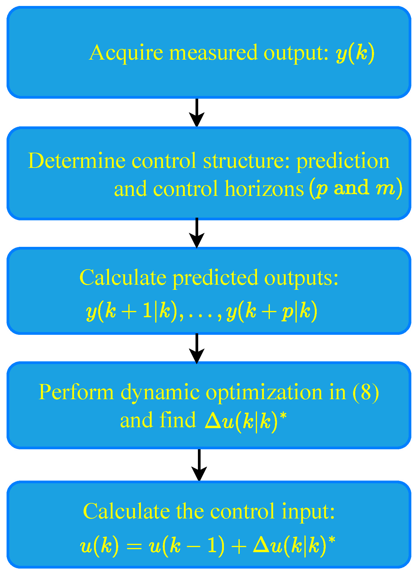
3.3. Model Predictive Control (MPC)

The retrofit MPC scheme employs the robust closed-loop system model in Figure 4 to calculate the required adjustments for control input u to limit interconnection current i i n t within predetermined bounds under the effect of disturbance and measurement noise. MPC actions take place at discrete-time instants. The interval between two consecutive instants is referred to as a sampling period or control interval [32].
The MPC law is shown in Figure 5. At present time k, system output y ( k ) is measured. In order to calculate control input u ( k ) , control horizon [ k k + m 1 ] of length m is considered. Based on this control horizon, the objective is to calculate the sequence of control increments Δ u ( k | k ) , Δ u ( k + 1 | k ) , …, Δ u ( k + m 1 | k ) , in which the notation Δ u ( k + i | k ) ( i = 0 , , m 1 ) denotes the calculated value of the control increment at time k + i in the future given measurement y ( k ) at present time k. The sequence of control increments Δ u ( k + i | k ) ( i = 0 , , m 1 ) is calculated by solving a constrained optimization problem including a cost function in terms of the sequence of control increments and a sequence of predicted system outputs over prediction horizon [ k + 1 k + p ] of length p ( p > m ) . The latter includes y ( k + 1 | k ) , , y ( k + p | k ) , in which the notation y ( k + i | k ) ( i = 1 , , p ) denotes the predicted value of the system output at time k + i in the future given measurement y ( k ) at present time k.
For each of the inverter systems, the discrete state-space model in (5) is used to formulate a constrained optimization problem in the MPC scheme. It consists of three cost functions:
J y = i = 1 p { w i y [ r ( k + i | k ) y ( k + i | k ) ] } 2 J u = i = 1 m { w i u [ Δ u ( k + i 1 | k ) ] } 2 J ϵ = w ϵ ϵ ( k ) 2
where J y , J u , and J ϵ represent the output, control input, and slack variable cost functions, respectively, and w i y , w i u , and w ϵ are dimensionless tuning weights to penalize reference tracking, control input increments, and constraint violations. Moreover, ϵ ( k ) represents the slack variable for the soft constraint in (7). Since the purpose of the retrofit MPC scheme in this paper is not to track a reference signal, r ( k + i | k ) in (6) is taken to be zero, and the ratio of w i y / w i u is chosen such that w i y w i u to put the lowest weight on the tracking objective.
The constraint inequality to restrain the interconnection current is formulated as
y m i n ϵ ( k ) S m i n < y ( k + i | k ) < y m a x + ϵ ( k ) S m a x
where y m i n and y m a x represent the lower and upper bounds of the interconnection current, respectively, and S m i n and S m a x represent the equal concern for the relaxation (ECR) values [32], which determines how much a constraint can be relaxed. The values of these parameters in this study are chosen as follows: y m i n = 10 , y m a x = 10 , and S m i n / m a x = 5 .
Combining all of the cost functions in (6), the optimization problem is formulated as
min Δ u ( k | k ) , , Δ u ( k + m 1 | k ) , ϵ ( k ) J y + J u + J ϵ s . t . ( 5 ) a n d ( 7 )
At each sampling interval k, (8) is solved by using a quadratic programming (QP) solver with respect to the sequence of input increments { Δ u ( k | k ) , , Δ u ( k + m 1 | k ) } and the slack variable ϵ ( k ) . However, according to the receding horizon concept, only the first element of the optimal sequence, Δ u ( k | k ) * , is selected to update the control input as u ( k ) = u ( k 1 ) + Δ u ( k | k ) * . In the case where the QP problem becomes infeasible due to numerical reasons, the second sample from the previous optimal input sequence is employed, as in u ( k ) = u ( k 1 ) + Δ u ( k | k 1 ) * . The flowchart of the MPC design process explained above is illustrated in Figure 6 and is summarized as follows:
  • Acquire the current values of measured output y ( k ) .
  • Determine the control structure: prediction and control horizons (p and m).
  • Calculate predicted outputs: y ( k + 1 | k ) , , y ( k + p | k ) .
  • Perform the optimization in (8) to compute the sequence of control increments Δ u ( k | k ) , Δ u ( k + 1 | k ) , …, Δ u ( k + m 1 | k ) , and set Δ u ( k | k ) * = Δ u ( k | k ) .
  • Calculate the control input: u ( k ) = u ( k 1 ) + Δ u ( k | k ) * .
Although the inverter systems are dynamically coupled as per Equations (4) and (5), the controller of each inverter system is designed independently by considering the neighboring inverter output voltage (state) v n as an external disturbance.
In the next section, the performance of the proposed retrofit MPC strategy is demonstrated and compared with the VI and retrofit LQR as benchmark techniques.

4. Simulation Results

An SSMG consisting of six inverter-based DERs was considered for the simulation studies, as shown in Figure 7. Table 2 lists the parameter values of all of the inverter systems. These systems are connected to each other via interconnection lines illustrated by impedances Z i j that include both inductive and resistive properties.
The proposed retrofit MPC scheme was applied to each of the inverter systems, and several simulation case studies were conducted to assess the performance of the closed-loop SSMG, including time response, peak load, plug-and-play capability, the effect of a nonlinear load, and robustness. All simulation results are compared with those of the VI and retrofit LQR schemes as benchmark methods. A virtual impedance control technique is usually used in the case of strong interconnection couplings among generation systems. Therefore, we used it as the benchmark method. In addition, we also compared our proposed technique with LQR as another extra benchmark method. It should be pointed out that, based on the IEEE 1250 standard [33], the voltage deviations of a bus should not exceed ± 10 % of its nominal value. This criterion is considered in all simulation analyses throughout this section. To save space, only the results for inverter 3 in Figure 7 are illustrated. It is noted that the MPC controller can attenuate system disturbances due to its predictive nature and capability to optimize control actions based on the system model. In other words, MPC solves an optimization problem at each control interval such that it can reduce the effect of unwanted oscillations from peak-load disturbances or harmonics from nonlinear loads. On the other hand, robustness against LC filter parameter variations is guaranteed by designing the inner robust controller using a μ -synthesis framework.

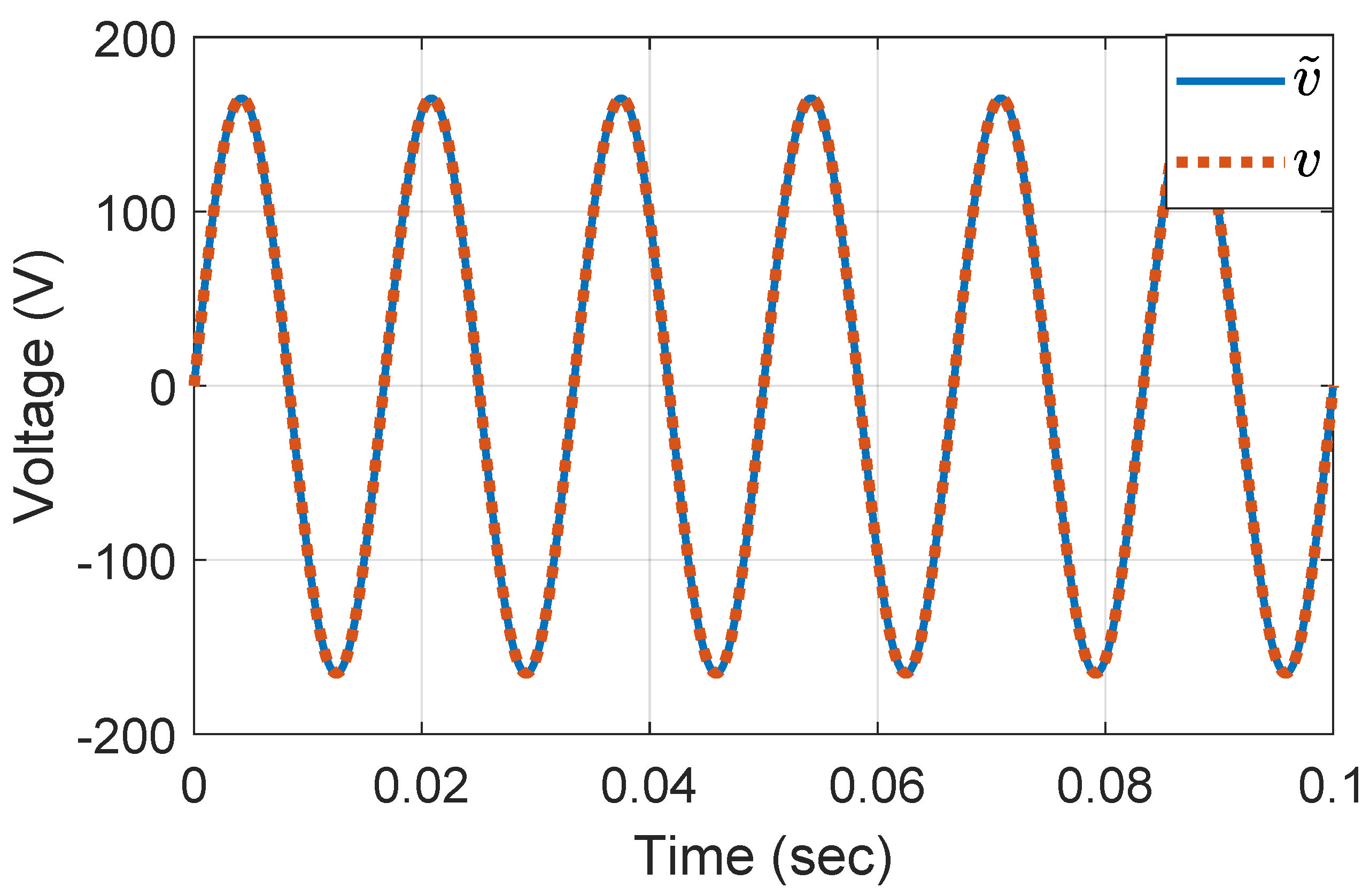
4.1. Time Response for Nominal Load

In this case study, the distance between every two inverter systems in Figure 7 is considered to be 200 (m). The remaining parameters, including LC filter parameters and load, are chosen to be their nominal values in Table 2. Moreover, all loads are assumed to be linear. Figure 8 demonstrates the capacitor voltage of inverter 3 ( I n v 3 ) in Figure 7 with the proposed retrofit MPC technique. The reference voltage amplitude for this inverter is considered to be 165 (V). As is observed, the capacitor voltage tracks the reference voltage. The proposed retrofit MPC structure in Figure 4 stabilizes the unstable system shown in Figure 3b. The performance of the VI control and retrofit LQR (benchmarks) methods is the same as the proposed MPC method for the case of the nominal load in Table 2. However, the amplitude of the reference voltage in the VI control scheme drops to 163 (V), which is still within ± 10 % of the nominal amplitude, 165 (V). Therefore, the retrofit MPC and LQR schemes and the VI control technique are able to stabilize the SSMG with the nominal load when the distances among inverters are 200 (m). However, the superiority of the proposed retrofit MPC scheme over its peers will be demonstrated next.

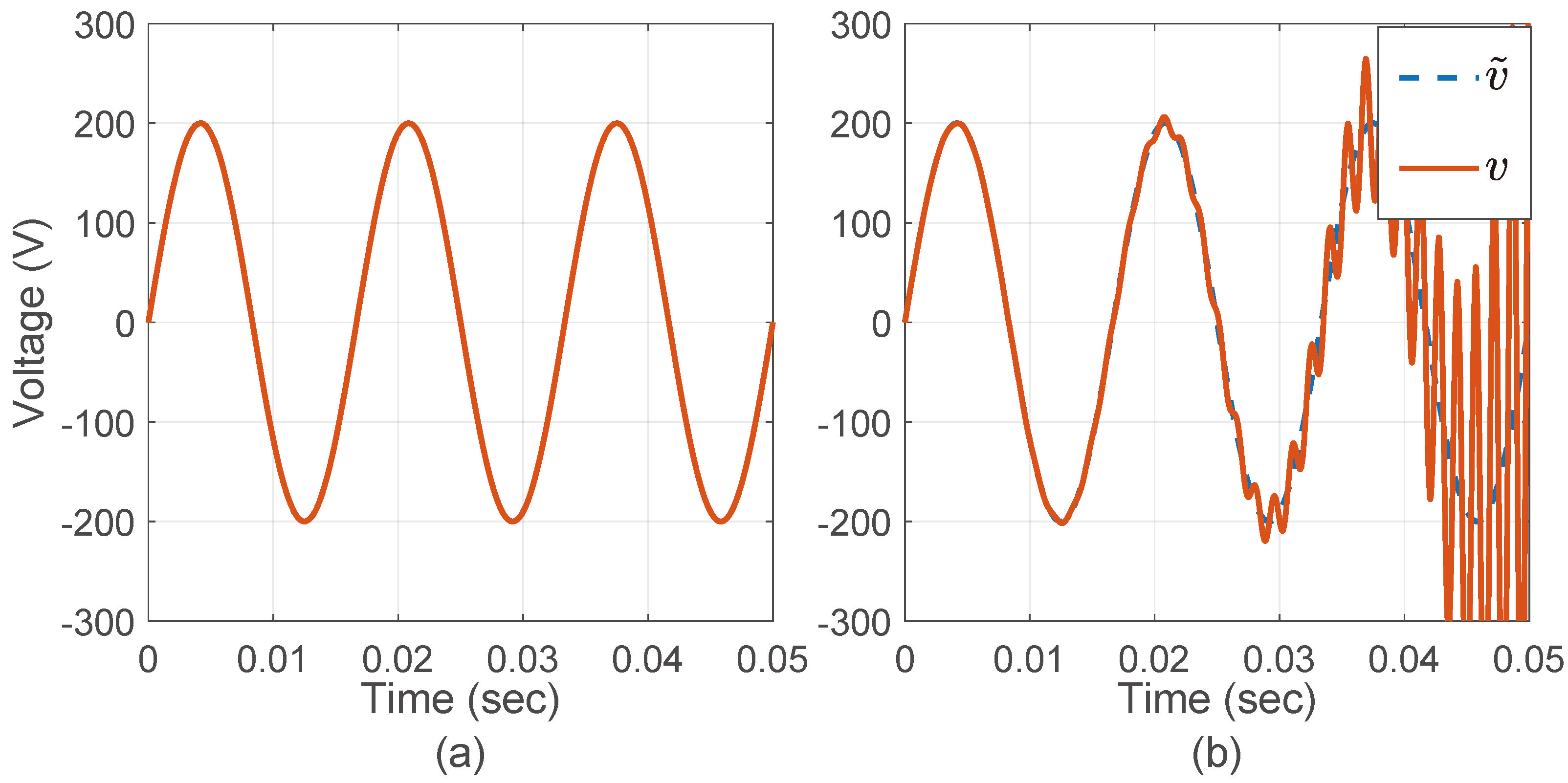
4.2. Peak-Load Analysis

In this case study, the effect of the peak-load demand on the performance of the system is investigated. The load demand of the SSMG can vary depending on the number of appliances used by the customers. The purpose here is to demonstrate that the proposed retrofit MPC scheme can damp the undesired oscillation resulting from the peak-load demand. According to [34], in the worst-case scenario, the active and reactive powers of a residential load are calculated to be around 21 (kW) and 10 (kVAR), respectively. This load is added to the SSMG at 0.054 (sec). The proposed retrofit MPC structure is capable of stabilizing the inverter system as per the capacitor voltage graph of inverter 3 ( I n v 3 ) in Figure 7 demonstrated in Figure 9. It can be observed in Figure 9b that when the load is introduced to the SSMG, the output voltage has a very small deviation from the reference voltage and is within ± 10 % of the nominal level. On the other hand, when its peers are used, the performance of the closed-loop system deteriorates significantly, as shown in Figure 10 and Figure 11. It is clear from Figure 10b and Figure 11b that the capacitor voltages go beyond the ± 10 % margins from the nominal voltage level.

4.3. Plug-And-Play Capability

It is essential that an inverter-interfaced SSMG maintains an acceptable performance in case some of the generation systems are disconnected/connected from/to the SSMG. This feature is called “plug-and-play” capability. Figure 12 illustrates the performance of inverter 3 ( I n v 3 ) in Figure 7 when inverters 5 and 6 are disconnected at t = 0.03 (sec) and connected back at t = 0.04 (sec) for the case of the proposed retrofit MPC scheme. It is observed that the resulting undesired oscillations have small amplitudes and are damped in a very short time. Moreover, the capacitor voltage deviations are within ± 10 % of the nominal value. On the other hand, when its peers are used, the performance of the inverter system deteriorates drastically. As shown in Figure 13 and Figure 14, the capacitor voltages exceed the ± 10 % limit when inverters 5 and 6 in Figure 7 are disconnected at t = 0.03 (sec). It should be noted that the phase of the reference voltage of a stand-alone inverter, before being plugged into the SSMG, is determined by using the phase-locked loop control system, which measures the phase of the SSMG at the point of connection. This procedure is carried out to synchronize the output of the inverters before plugging them into the SSMG.

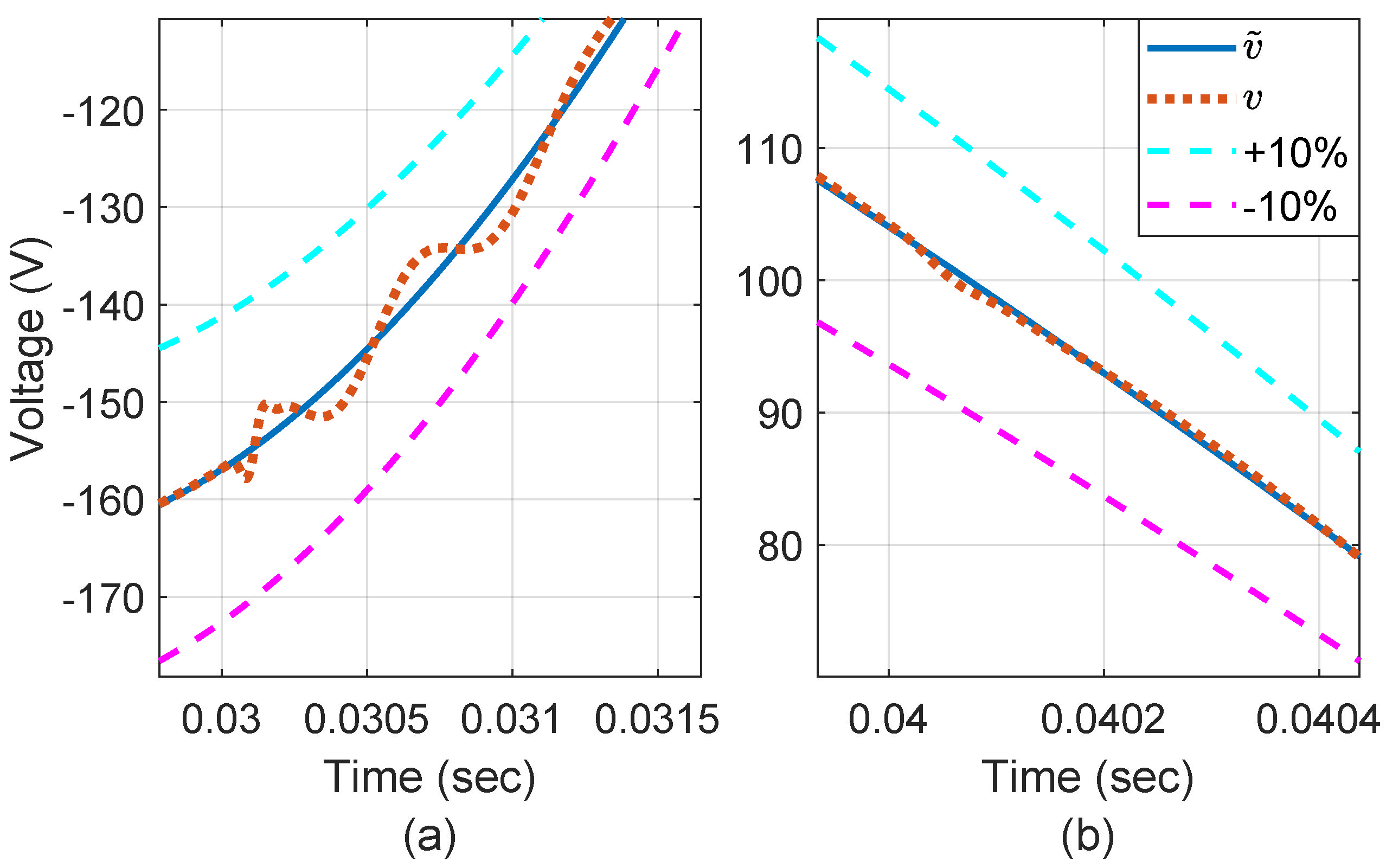
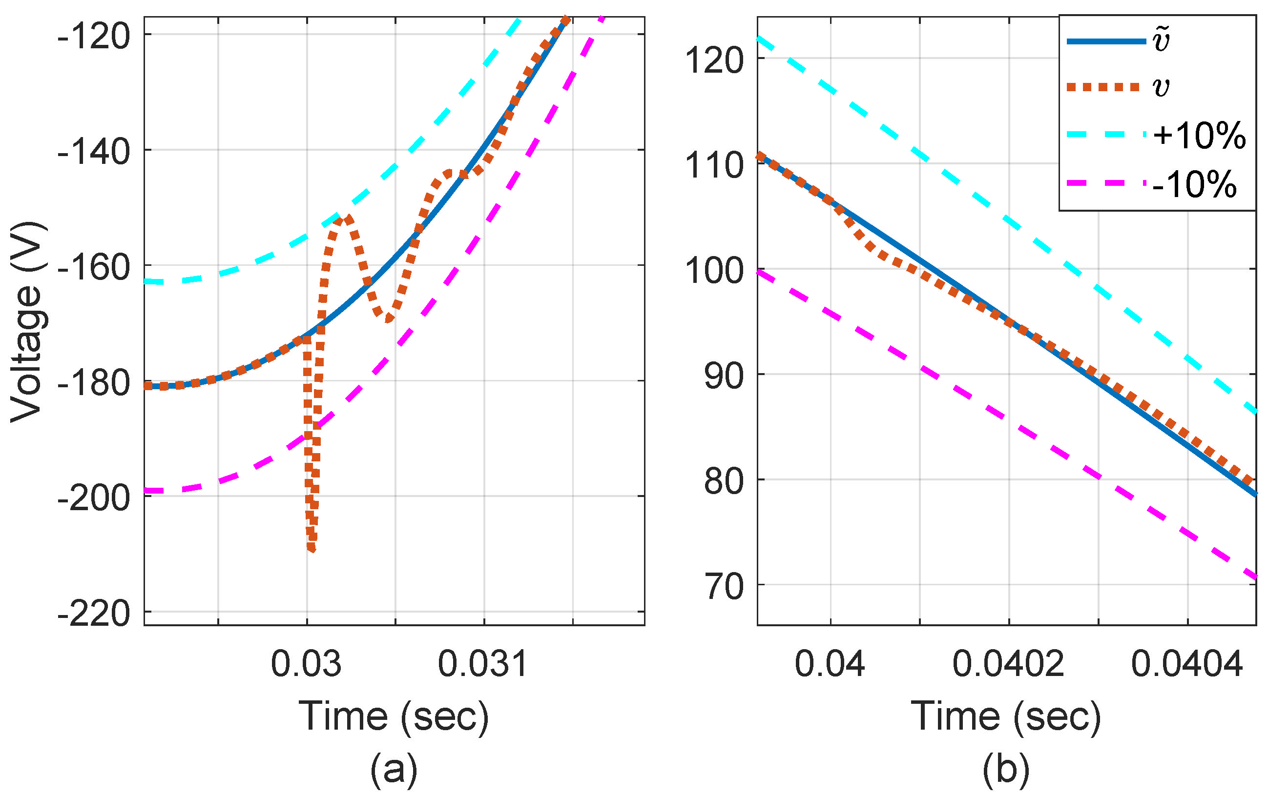
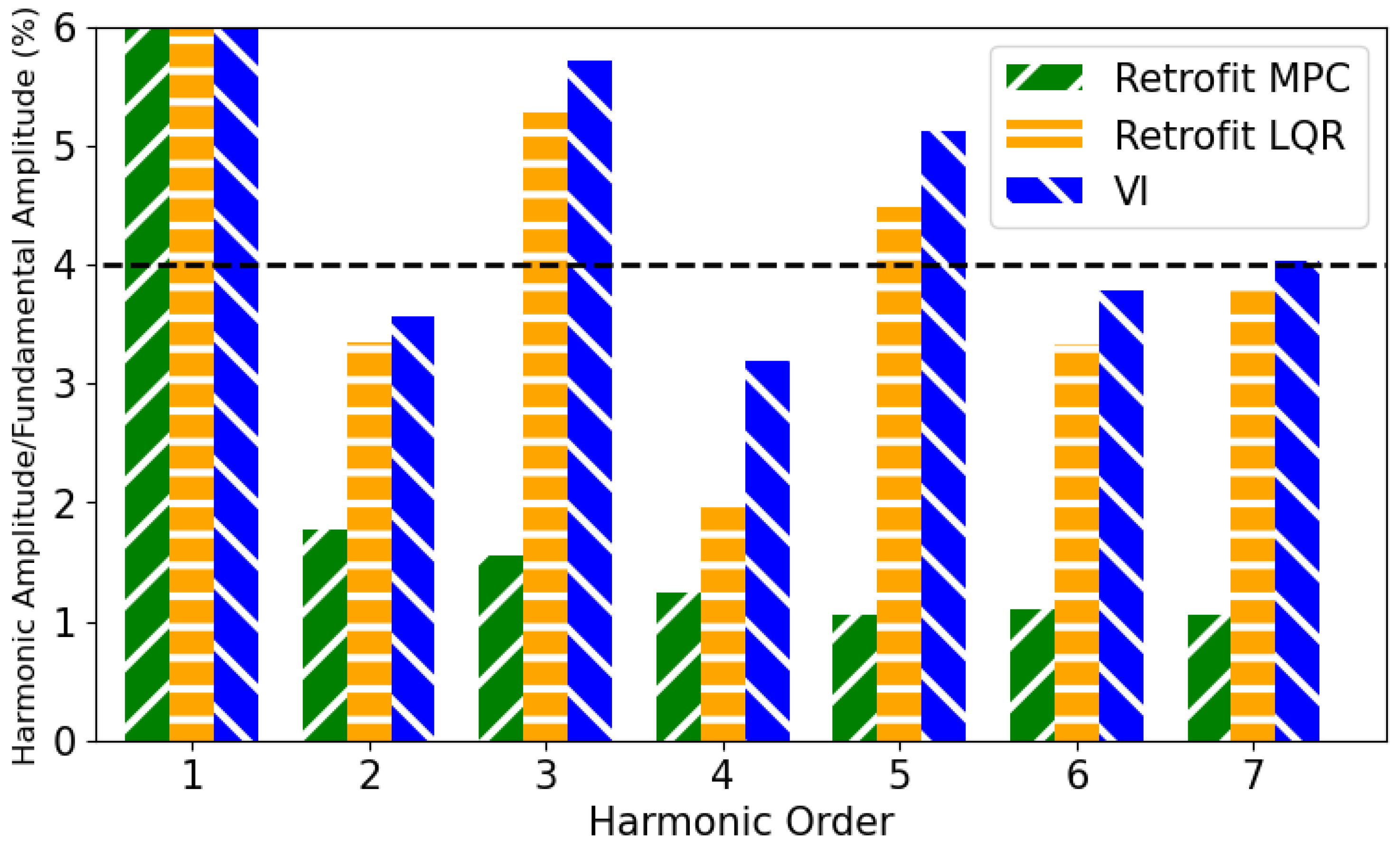
4.4. Effect of Nonlinear Load
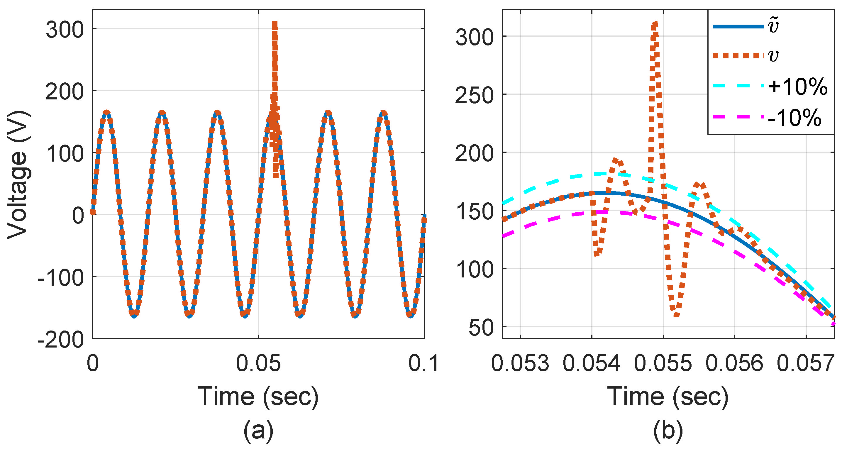
Nonlinear loads have become integral components of modern power systems due to the significant growth of power electronic equipment such as uninterrupted power supply and rectifiers. Nevertheless, such loads introduce harmonics into current and voltage waveforms, which, in turn, negatively impact the quality of the generated electrical power [35]. In this paper, a diode rectifier is employed to model a nonlinear load, which is a ubiquitous model in the study of power systems [36,37]. By applying this nonlinear load, the load current becomes distorted, which consequently impacts the voltage of a capacitor. Figure 15 illustrates the harmonic contents of the capacitor voltage for the distorted nonlinear load current. According to the IEEE 1547 standard [38], the maximum harmonic voltage distortion for harmonics less than 11 should be 4 % . As observed in Figure 15, the proposed retrofit MPC scheme maintains the harmonic voltage distortions below this limit, while its peers exceed the limit for the third and fifth harmonics.

4.5. Robustness

As mentioned in Section 2.2, the closed-loop system should be robust against ± 20 % variations in the LC filter parameters. Figure 16 demonstrates the robust performance of the proposed retrofit MPC strategy against ± 20 % parameter variations. Its peers have the same robust performance. It is observed that all control strategies in this paper have the same robust performance since LC filter parameter uncertainties have been considered in the design of their voltage source inverter robust controllers.

4.6. Inverter Efficiency

Inverter efficiency describes how effectively an inverter can convert DC power into AC power and is measured as the inverter’s output power divided by the inverter’s input power. In this study, we also conducted an inverter efficiency analysis, and the results for the microgrid controllers designed using MPC, VI, and LQR are 98.2 % , 95.6 % , and 96.3 % , respectively. These results demonstrate the superior performance of the proposed controller in terms of inverter efficiency.

5. Conclusions

In this paper, a retrofit model predictive controller is proposed and designed for the decentralized robust control of an SSMG in which the distances among inverter systems are less than 200 (m). This is equivalent to an R / X ratio of 7.74, which is the actual ratio in distribution systems. To the best of our knowledge, none of the existing work has considered this ratio for an SSMG. In such an SSMG, the interconnection couplings among the inverter systems are so strong that they lead to its instability. The design procedure is performed for each inverter system completely independently of the rest of the SSMG. To design a retrofit controller, we require only the models of inverter systems and interconnection lines among them. A voltage source inverter robust controller was previously designed in our prior work [14] for each of the inverter systems by using a μ -synthesis technique, considering the interconnection current as an external disturbance. In this paper, by placing the interconnection model into the system, the interconnection current is measured and fed into the retrofit model predictive controller. This controller generates a control command signal to limit the measured interconnection current within some predefined bounds by solving a constrained optimization problem. The generated control command is then added to the pre-existing control command coming from the voltage source inverter robust controller. The performance of the proposed retrofit model predictive controller is compared with two benchmark methods, i.e., those of the virtual impedance and retrofit linear quadratic regulator. Based on the simulation results, the proposed controller outperforms two benchmarks in the case of peak-load demand, plug-and-play operation, nonlinear loads, and inverter efficiency. Regarding robustness, all controllers have the same performance since their robust controllers are designed similarly by considering the LC filter parameter uncertainties. In conclusion, the proposed retrofit model predictive control technique provides an outstanding solution to the problem of instability in a small-scale microgrid, which includes strongly coupled inverter systems connected by short interconnection lines. However, this approach is more computationally expensive than the other benchmark techniques. Moreover, it needs an extra current sensor to measure the interconnection current. Therefore, in future research work, state estimators will be designed and developed to estimate the interconnection current instead of using an extra current sensor.

Author Contributions

Conceptualization, S.M.A.; methodology, M.S.; software, M.S.; validation, M.S.; data curation, M.S.; writing—original draft preparation, M.S.; writing—review and editing, M.S. and S.M.A.; visualization, M.S.; supervision, S.M.A. All authors have read and agreed to the published version of the manuscript.

Funding

This research received no external funding.

Data Availability Statement

Derived data supporting the findings of this study are available from the corresponding author on request.

Conflicts of Interest

The authors declare no conflict of interest.

References

  1. Haidar, A.M.; Muttaqi, K.; Sutanto, D. Smart Grid and its future perspectives in Australia. Renew. Sustain. Energy Rev. 2015, 51, 1375–1389. [Google Scholar] [CrossRef]
  2. Uski, S.; Kim, I. Assessment of wind power impact on power system transmission losses. In Proceedings of the IEEE PES Innovative Smart Grid Technologies, Europe, Istanbul, Turkey, 12–15 October 2014; pp. 1–5. [Google Scholar]
  3. Shakiba, F.M.; Azizi, S.M.; Zhou, M.; Abusorrah, A. Application of machine learning methods in fault detection and classification of power transmission lines: A survey. Artif. Intell. Rev. 2023, 56, 5799–5836. [Google Scholar] [CrossRef]
  4. The Global Carbon Project. Available online: https://www.globalcarbonproject.org/ (accessed on 16 July 2024).
  5. IEA. Number of People without Access to Electricity Worldwide from 2000 to 2021, by Region (in Millions). Available online: https://www.statista.com/statistics/829803/number-of-people-without-access-to-electricity-by-region/ (accessed on 16 July 2024).
  6. Akinyele, D.; Rayudu, R.; Nair, N. Development of photovoltaic power plant for remote residential applications: The socio-technical and economic perspectives. Appl. Energy 2015, 155, 131–149. [Google Scholar] [CrossRef]
  7. Li, P.; Yu, D.; Yang, M.; Wang, J. Flexible Look-Ahead Dispatch Realized by Robust Optimization Considering CVaR of Wind Power. IEEE Trans. Power Syst. 2018, 33, 5330–5340. [Google Scholar] [CrossRef]
  8. Shim, J.W.; Verbič, G.; Hur, K. Stochastic Eigen-Analysis of Electric Power System With High Renewable Penetration: Impact of Changing Inertia on Oscillatory Modes. IEEE Trans. Power Syst. 2020, 35, 4655–4665. [Google Scholar] [CrossRef]
  9. Shojaee, M.; Azizi, S.M. Sequential Design of Decentralized Robust Controllers for Strongly Interconnected Inverter-Based Distributed Generation Systems: A Comparative Study versus Independent Design. Energies 2022, 15, 8995. [Google Scholar] [CrossRef]
  10. Khan, A.; Khan, M.M.; Li, Y.; Chuanwen, J.; Shahid, M.U.; Khan, I. A robust control scheme for voltage and reactive power regulation in islanded AC microgrids. Electr. Power Syst. Res. 2022, 210, 108179. [Google Scholar] [CrossRef]
  11. Zhong, W.; Tzounas, G.; Milano, F. Improving the power system dynamic response through a combined voltage-frequency control of distributed energy resources. IEEE Trans. Power Syst. 2022, 37, 4375–4384. [Google Scholar] [CrossRef]
  12. Derakhshan, S.; Shafiee-Rad, M.; Shafiee, Q.; Jahed-Motlagh, M.R. Decentralized Robust LMI-based Voltage Control Strategy for Autonomous Inverter-Interfaced Multi-DG Microgrids. IEEE Trans. Power Syst. 2022, 38, 3003–3015. [Google Scholar] [CrossRef]
  13. Sadabadi, M.S.; Shafiee, Q.; Karimi, A. Plug-and-Play Voltage Stabilization in Inverter-Interfaced Microgrids via a Robust Control Strategy. IEEE Trans. Control Syst. Technol. 2017, 25, 781–791. [Google Scholar] [CrossRef]
  14. Azizi, S.M.; Khajehoddin, S.A. Robust inverter control design in islanded microgrids using μ-synthesis. In Proceedings of the 2016 IEEE Energy Conversion Congress and Exposition (ECCE), Milwaukee, WI, USA, 18–22 September 2016; pp. 1–5. [Google Scholar] [CrossRef]
  15. Vijay, A.S.; Parth, N.; Doolla, S.; Chandorkar, M.C. An Adaptive Virtual Impedance Control for Improving Power Sharing Among Inverters in Islanded AC Microgrids. IEEE Trans. Smart Grid 2021, 12, 2991–3003. [Google Scholar] [CrossRef]
  16. Alfaro, C.; Guzman, R.; De Vicuna, L.G.; Komurcugil, H.; Martín, H. Distributed direct power sliding-mode control for islanded AC microgrids. IEEE Trans. Ind. Electron. 2021, 69, 9700–9710. [Google Scholar] [CrossRef]
  17. Mosayebi, M.; Gheisarnejad, M.; Khooban, M.H. An Intelligent Type-2 Fuzzy Stabilization of Multi-DC Nano Power Grids. IEEE Trans. Emerg. Top. Comput. Intell. 2021, 5, 854–859. [Google Scholar] [CrossRef]
  18. Wang, Y.; Qiu, D.; Wang, Y.; Sun, M.; Strbac, G. Graph Learning-Based Voltage Regulation in Distribution Networks with Multi-Microgrids. IEEE Trans. Power Syst. 2023, 39, 1881–1895. [Google Scholar] [CrossRef]
  19. Afshari, A.; Davari, M.; Karrari, M.; Gao, W.; Blaabjerg, F. A Multivariable, Adaptive, Robust, Primary Control Enforcing Predetermined Dynamics of Interest in Islanded Microgrids Based on Grid-Forming Inverter-Based Resources. IEEE Trans. Autom. Sci. Eng. 2023, 11, 92589–92616. [Google Scholar] [CrossRef]
  20. He, L.; Li, Y.; Guerrero, J.M.; Cao, Y. A Comprehensive Inertial Control Strategy for Hybrid AC/DC Microgrid With Distributed Generations. IEEE Trans. Smart Grid 2020, 11, 1737–1747. [Google Scholar] [CrossRef]
  21. Abadi, S.A.G.K.; Khalili, T.; Habibi, S.I.; Bidram, A.; Guerrero, J.M. Adaptive control and management of multiple nano-grids in an islanded dc microgrid system. IET Gener. Transm. Distrib. 2022, 17, 1799–1815. [Google Scholar] [CrossRef]
  22. Rocabert, J.; Luna, A.; Blaabjerg, F.; Rodriguez, P. Control of power converters in AC microgrids. IEEE Trans. Power Electron. 2012, 27, 4734–4749. [Google Scholar] [CrossRef]
  23. Xu, Y.; Yi, Z. Chapter 3–Optimal distributed secondary control for an islanded microgrid. In Distributed Control Methods and Cyber Security Issues in Microgrids; Academic Press: Cambridge, MA, USA, 2020; pp. 59–81. [Google Scholar]
  24. Caiazzo, B.; Lui, D.G.; Petrillo, A.; Santini, S. Cooperative Adaptive PID-Like Voltage Regulation in Inverter-Based Islanded Microgrids Under Unknown Uncertainties. IEEE Syst. J. 2023, 17, 4395–4406. [Google Scholar] [CrossRef]
  25. Jha, S.K.; Kumar, D.; Tripathi, P.R.; Appasani, B.; Zawbaa, H.M.; Kamel, S. An adaptive vector control method for inverter-based stand-alone microgrids considering voltage reduction and load shedding schemes. IET Gener. Transm. Distrib. 2023, 17, 2703–2717. [Google Scholar] [CrossRef]
  26. Amouzegar Ashtiani, N.; Azizi, S.M.; Khajehoddin, S.A. Robust Control Design for High-Power Density PV Converters in Weak Grids. IEEE Trans. Control Syst. Technol. 2019, 27, 2361–2373. [Google Scholar] [CrossRef]
  27. Azizi, S.M. Robust Controller Synthesis and Analysis in Inverter-Dominant Droop-Controlled Islanded Microgrids. IEEE/CAA J. Autom. Sin. 2021, 8, 1401–1415. [Google Scholar] [CrossRef]
  28. Shojaee, M.; Azizi, S.M. Decentralized Robust Control of a Coupled Wind Turbine and Diesel Engine Generator System. IEEE Trans. Power Syst. 2023, 38, 807–817. [Google Scholar] [CrossRef]
  29. Ishizaki, T.; Sadamoto, T.; Imura, J.i.; Sandberg, H.; Johansson, K.H. Retrofit control: Localization of controller design and implementation. Automatica 2018, 95, 336–346. [Google Scholar] [CrossRef]
  30. Sadamoto, T.; Ishizaki, T.; Imura, J.i.; Sandberg, H.; Johansson, K.H. Retrofitting state feedback control of networked nonlinear systems based on hierarchical expansion. In Proceedings of the 2016 IEEE 55th Conference on Decision and Control (CDC), Las Vegas, NV, USA, 12–14 December 2016; pp. 3432–3437. [Google Scholar]
  31. Sadamoto, T.; Chakrabortty, A.; Ishizaki, T.; Imura, J.i. Retrofit control of wind-integrated power systems. IEEE Trans. Power Syst. 2017, 33, 2804–2815. [Google Scholar] [CrossRef]
  32. Bemporad, A.; Morari, M.; Ricker, N.L. Model predictive control toolbox user’s guide. Mathworks 2010. [Google Scholar]
  33. IEEE Std 1250 (Revision of IEEE Std 1250-2011); Guide for Identifying and Improving Voltage Quality in Power System. IEEE: Piscataway, NJ, USA, 2018; p. 27.
  34. Anderson, H.C.; Al Hadi, A.; Jones, E.S.; Ionel, D.M. Power Factor and Reactive Power in US Residences – Survey and EnergyPlus Modeling. In Proceedings of the 2021 10th International Conference on Renewable Energy Research and Application (ICRERA), Istanbul, Turkey, 26–29 September 2021; pp. 418–422. [Google Scholar]
  35. Gheisarnejad, M.; Mohammadi-Moghadam, H.; Boudjadar, J.; Khooban, M.H. Active Power Sharing and Frequency Recovery Control in an Islanded Microgrid With Nonlinear Load and Nondispatchable DG. IEEE Syst. J. 2020, 14, 1058–1068. [Google Scholar] [CrossRef]
  36. Kumar, P.; Kumar, N.; Akella, A. A simulation based case study for control of DSTATCOM. ISA Trans. 2014, 53, 767–775. [Google Scholar] [CrossRef]
  37. Ranjbaran, A.; Ebadian, M. A power sharing scheme for voltage unbalance and harmonics compensation in an islanded microgrid. Electr. Power Syst. Res. 2018, 155, 153–163. [Google Scholar] [CrossRef]
  38. IEEE Std 1547-2003; Standard for Interconnecting Distributed Resources with Electric Power Systems. IEEE: Piscataway, NJ, USA, 2003; pp. 1–28. [CrossRef]
Figure 1. The voltage source inverter with an LC filter.
Electronics 13 02914 g001
Figure 2. A block diagram of a closed-loop robust control system.
Electronics 13 02914 g002
Figure 3. The time response of the robust decentralized controllers for (a) 1 (km) distance and (b) 200 (m) distance between the inverters.
Electronics 13 02914 g003
Figure 4. A block diagram of the proposed retrofit control scheme.
Electronics 13 02914 g004
Figure 5. MPC strategy.
Electronics 13 02914 g005
Figure 6. MPC design flowchart.
Electronics 13 02914 g006
Figure 7. SSMG including six inverter-based DERs.
Electronics 13 02914 g007
Figure 8. The capacitor voltage of inverter 3 ( I n v 3 ) in Figure 7 with the proposed retrofit MPC structure for 200 (m) distance between every two inverters.
Electronics 13 02914 g008
Figure 9. The capacitor voltage of inverter 3 ( I n v 3 ) of the SSMG illustrated in Figure 7 with the proposed retrofit MPC structure when 21 (kW) and 10 (kVAR) loads are applied at 0.054 (sec): (a) full scale and (b) zoomed scale.
Electronics 13 02914 g009
Figure 10. The capacitor voltage of inverter 3 ( I n v 3 ) of the SSMG illustrated in Figure 7 with the VI control scheme (benchmark), when 21 (kW) and 10 (kVAR) loads are applied at 0.054 (sec): (a) full scale and (b) zoomed scale.
Electronics 13 02914 g010
Figure 11. The capacitor voltage of inverter 3 ( I n v 3 ) of the SSMG illustrated in Figure 7 with the retrofit LQR control scheme (benchmark) when 21 (kW) and 10 (kVAR) loads are applied at 0.054 (sec): (a) full scale and (b) zoomed scale.
Electronics 13 02914 g011
Figure 12. The capacitor voltage of inverter 3 ( I n v 3 ) of the SSMG illustrated in Figure 7 with the proposed retrofit MPC structure when inverter systems 5 and 6 are (a) disconnected at t = 0.03 (sec) and (b) connected back at t = 0.04 (sec).
Electronics 13 02914 g012
Figure 13. The capacitor voltage of inverter 3 ( I n v 3 ) of the SSMG illustrated in Figure 7 with the VI control scheme (benchmark) when inverter systems 5 and 6 are (a) disconnected at t = 0.03 (sec) and (b) connected back at t = 0.04 (sec).
Electronics 13 02914 g013
Figure 14. The capacitor voltage of inverter 3 ( I n v 3 ) of the SSMG illustrated in Figure 7 with the retrofit LQR control scheme (benchmark) when inverter systems 5 and 6 are (a) disconnected at t = 0.03 (sec) and (b) connected back at t = 0.04 (sec).
Electronics 13 02914 g014
Figure 15. Harmonic contents of the capacitor voltage of inverter 3 ( I n v 3 ) in Figure 7 for the case of the distorted nonlinear load current. The dashed line represents the IEEE 1547 standard.
Electronics 13 02914 g015
Figure 16. The capacitor voltage of inverter 3 ( I n v 3 ) of the SSMG illustrated in Figure 7 with the proposed retrofit MPC structure subject to 20 % parameter uncertainty.
Electronics 13 02914 g016
Table 1. Characteristics and performance of previous studies as compared to the results of this paper. R / X : Resistance-to-Reactance Ratio, v ^ : harmonic voltage distortion, P & P : plug-and-play capability, NM: Not Mentioned.
Ref.Voltage
Control
Scheme
R/X Robustness
Parameters
Overload
Analysis
Nonlinear
Load
P&P
[19]Multivariable,
adaptive,
robust
0.76NM Δ V < ± 10 % v ^ 4 % NM
[18]MPCNMNM Δ V < ± 10 % NMNM
[24]Adaptive PIDNMNM Δ V < ± 10 % NMNM
[25]AdaptiveNMNM Δ V < ± 10 % NMNM
[10]Impedance
Estimator
+ Optimal
0.32LC filter Δ V < ± 10 % NMNM
[11]PI+washout filter1NM Δ V < ± 10 % NMNM
[12]Robust LMI-based5.3LC filterNMNMYes
[13]Robust LMI-based0.01LC filterNMNMYes
[16]Sliding mode3.33LC filterNM v ^ 4 % Yes
This workRetrofit robust7.74LC filter Δ V < ± 10 % v ^ 4 % Yes
Table 2. The inverter system’s nominal parameter values.
Inverter 1 L 1 = 3.0 (mH), C 1 = 2.0 ( μ F),
L l o a d 1 = 1.0 (H), R l o a d 1 = 630 ( Ω )
Inverter 2 L 2 = 2.8 (mH), C 2 = 2.2 ( μ F),
L l o a d 2 = 1.2 (H), R l o a d 2 = 632 ( Ω )
Inverter 3 L 3 = 2.9 (mH), C 3 = 2.1 ( μ F),
L l o a d 3 = 0.9 (H), R l o a d 3 = 628 ( Ω )
Inverter 4 L 4 = 3.2 (mH), C 4 = 2.3 ( μ F),
L l o a d 4 = 1.3 (H), R l o a d 4 = 635 ( Ω )
Inverter 5 L 5 = 3.1 (mH), C 5 = 2.2 ( μ F),
L l o a d 5 = 1.1 (H), R l o a d 5 = 631 ( Ω )
Inverter 6 L 6 = 2.7 (mH), C 6 = 1.9 ( μ F),
L l o a d 6 = 1.4 (H), R l o a d 6 = 634 ( Ω )
Interconnection Lines R l = 0.642 ( Ω /km),
L l = 2.2 × 10 4 (H/km) [22]
Disclaimer/Publisher’s Note: The statements, opinions and data contained in all publications are solely those of the individual author(s) and contributor(s) and not of MDPI and/or the editor(s). MDPI and/or the editor(s) disclaim responsibility for any injury to people or property resulting from any ideas, methods, instructions or products referred to in the content.

