
Multifrequency Impedance Characterization for Radio Frequency Identification Chip


Abstract
1. Introduction
2. Quality Criteria Definition
2.1. Introduction
2.2. Processing Method
- -
- Generate an “ideal” target signal in MATLAB with consistent rise and fall times throughout the entire frame length, and noise free.
- -
- Perform a fast Fourier transform (FFT) on this target signal to obtain its frequency spectrum. It is the upper grey arrow on Figure 1.
- -
- Select a portion of the frequency range around the carrier frequency from the target signal’s spectrum.
- -
- Reconstruct a transient signal using this restricted spectrum via an inverse fast Fourier transform (IFFT), producing our reconstructed signal. This is represented by the bottom grey arrow on Figure 1.
- -
- Perform I/Q demodulation on both the transient signals to obtain signal envelopes.
- -
- Compare the transition times and envelope amplitudes of the target and reconstructed signals.
- -
- To determine the minimum frequency range, iterate the process by progressively widening the frequency range around the selected carrier frequency. The carrier frequency, denoted as “fc”, is 13.56 MHz.
2.3. Results
2.4. Discussion
3. Multifrequency Impedance Measurement
3.1. Measurement Principle
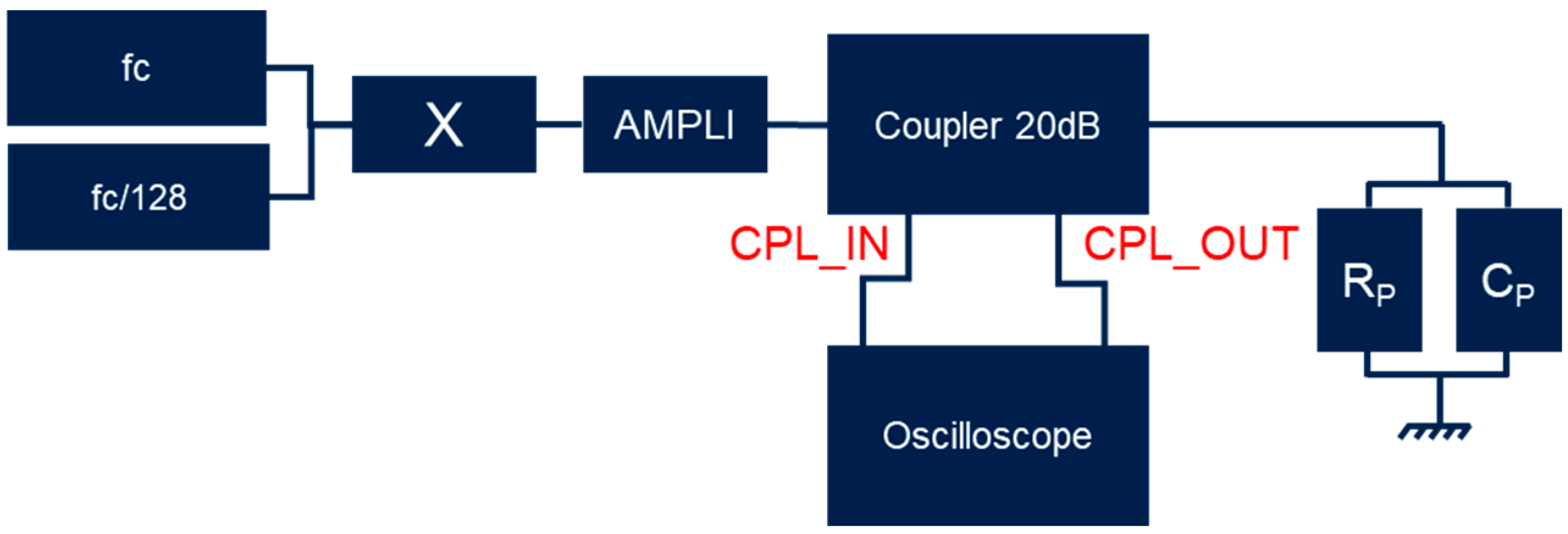
3.2. Measurement Setup
4. Validation of the Method on Passive Components
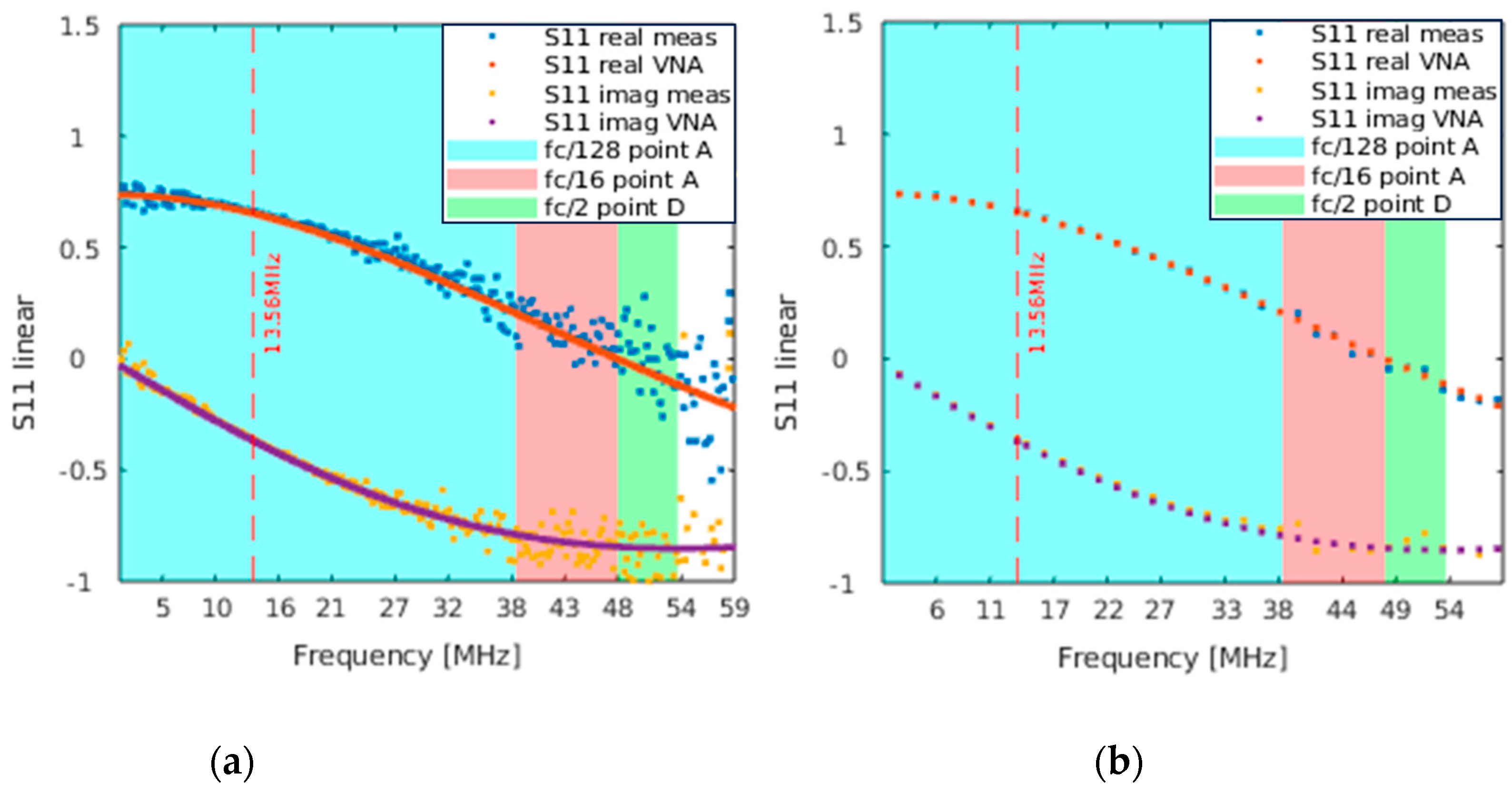
4.1. S11 Measure
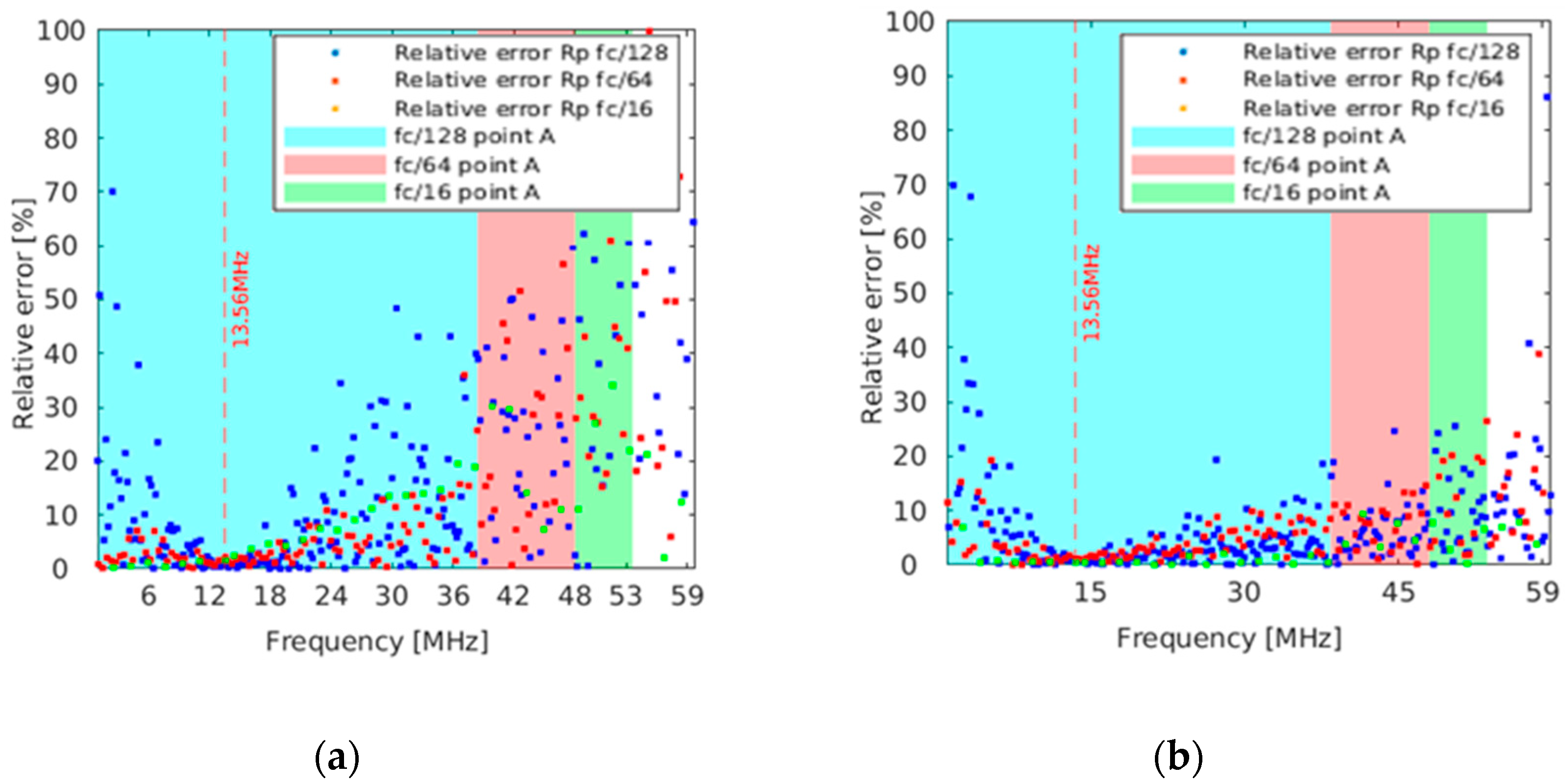
4.2. Equivalent RpCp Model
5. On Chip Measurement
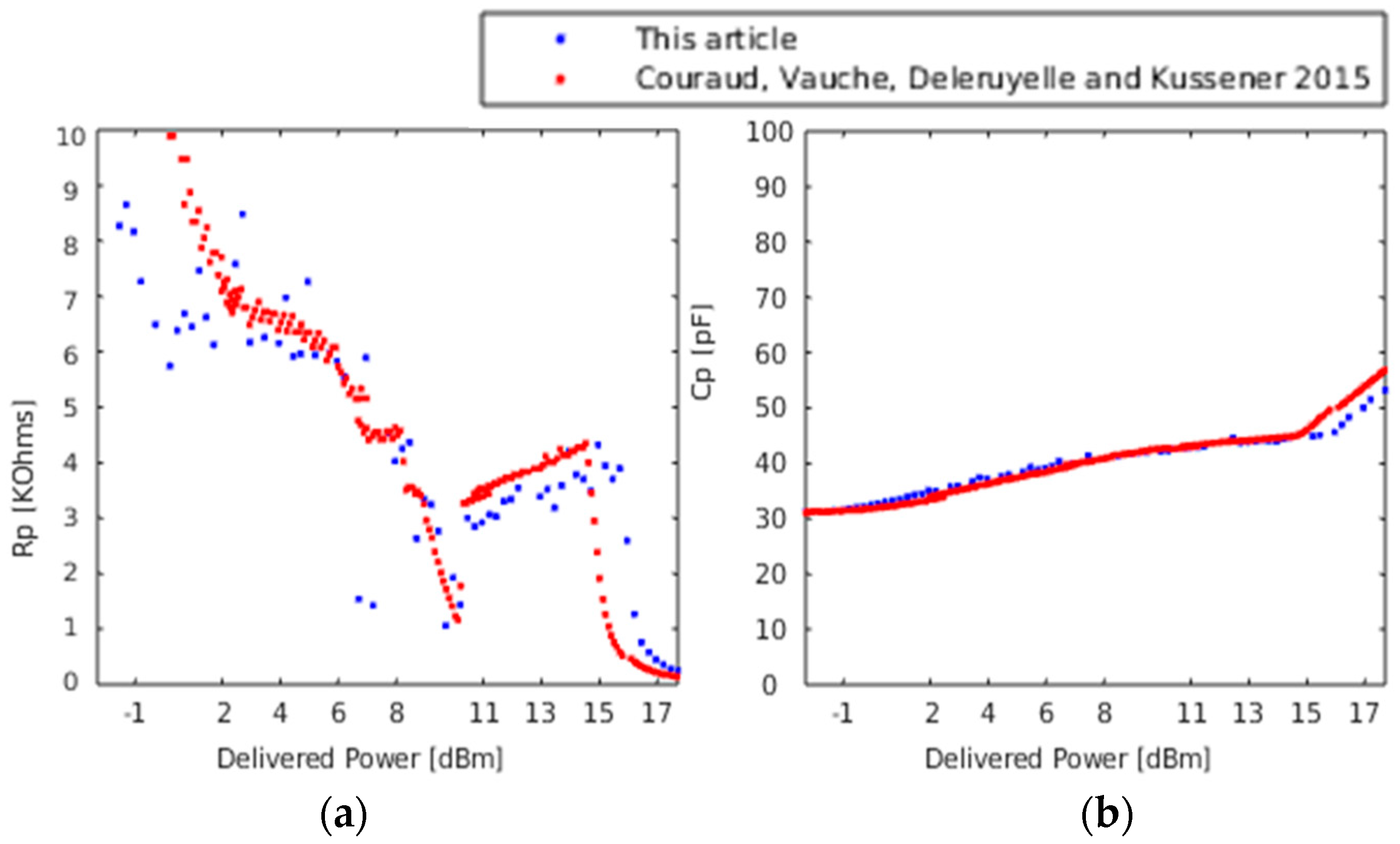
5.1. Mono-Frequency Comparison
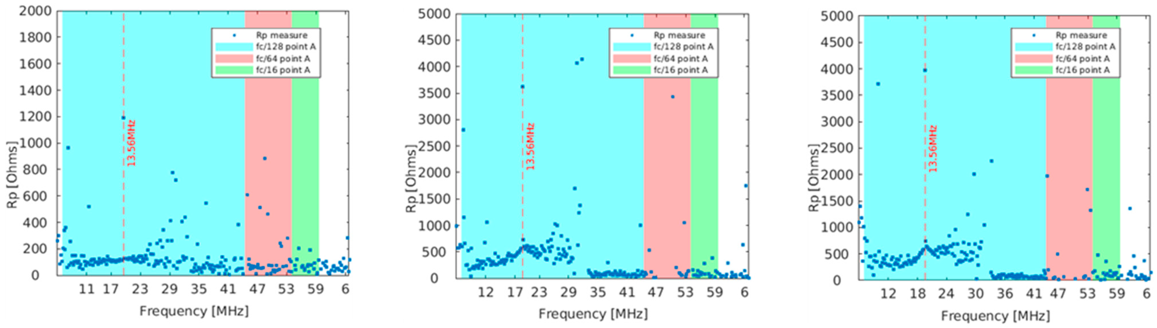
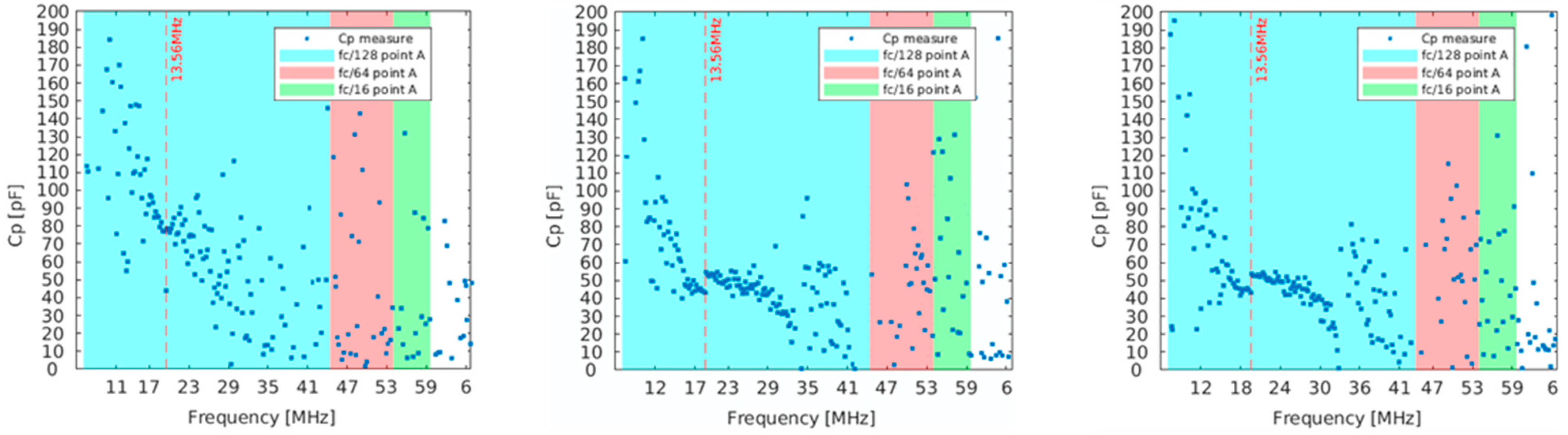
5.2. Multifrequency Measurement
6. Discussion
7. Conclusions
Author Contributions
Funding
Data Availability Statement
Conflicts of Interest
References
- ISO/IEC 14443-2:2020/Cor 2:2023; Cards and Security Devices for Personal Identification—Contactless Proximity Objects—Part 2: Radio Frequency Power and Signal Interface. ISO: Geneva, Switzerland, 2010. Available online: https://www.iso.org/standard/50941.html (accessed on 1 May 2022).
- Standard ISO/IEC 18000-3; Information Technology—Radio Frequency Identification for Item Management—Part 3: Parameters for Air Interface Communications at 13.56 MHz. ISO: Geneva, Switzerland, 2019. Available online: http://www.iso.org/ (accessed on 1 May 2022).
- Grosinger, J.; Deutschmann, B.J.B.; Zoscher, L.; Gadringer, M.; Amtmann, F. HF RFID Tag Chip Impedance Measurements. IEEE Trans. Instrum. Meas. 2022, 71, 1–11. [Google Scholar] [CrossRef]
- Sandler, S.M. Extending the usable range of the 2-port shunt through impedance measurement. In Proceedings of the 2016 IEEE MTT-S Latin America Microwave Conference, Puerto Vallarta, Mexico, 12–14 December 2016; pp. 1–3. [Google Scholar] [CrossRef]
- Couraud, B.; Vauche, R.; Deleruyelle, T.; Kussener, E. A low-cost impedance measurement method for integrated circuits. In Proceedings of the 2015 IEEE 16th International Conference on Communication Technology (ICCT), Hangzhou, China, 18–20 October 2015; pp. 13–16. [Google Scholar]
- Trois méthodes de Mesures D’impédances avec un Analyseur de réseau Vectoriel (VNA). Mesures du Coefficient de Self-Induction de Bobines et de la Capacité de Condensateurs en Radiofréquence (HF, VHF, UHF, SHF). Jean-François Flamée, UBA Liège, 2020; pp. 1–83. Available online: https://on5vl.org/wp-content/uploads/2024/06/Mesures_Impedances.pdf (accessed on 1 May 2022).
- Finkenzeller, K. RFID Handbook—Radio-Frequency Identification Fundamentals and Applications; Wiley: New York, NY, USA, 1999; ISBN 0-471-98851-0. [Google Scholar]
- Dunsmore, J.P. Handbook of Microwave Component Measurements with Advanced VNA Techniques; Wiley: New York, NY, USA, 2020; ISBN 978-1-119-47713-6. [Google Scholar]


| Type and Bit Rate | Type A fc/128 | Type B fc/N |
|---|---|---|
| Target tolerance | ±1% | ±0.5% |
| Bit Rate fc/N | N = 128 | N = 64 | N = 32, 16, 4, 2 |
|---|---|---|---|
| Bit Rate Mbps | 0.106 | 0.212 | 0.424, 0.847, 3.39, 6.78 |
| Target tolerance | ±1/fc | ±0.5/fc | ±0.3/fc |
| Target tolerance [µs] | ±73.74 | ±36.87 | ±24.58 |
| Bit Rate fc/N | Point | Lowest Frequency [MHz] | Highest Frequency [MHz] |
|---|---|---|---|
| N = 128 | D | 10.63 | 16.67 |
| G | 10.03 | 25.05 | |
| A | 1.01 | 38.04 | |
| N = 16 | D | 6.29 | 19.99 |
| G | 1.88 | 25.96 | |
| A | 1.00 | 47.99 | |
| N = 2 | D | F1.00 | 53.64 |
| G | 1.00 | 51.00 | |
| A | 1.06 | 50.92 |
Disclaimer/Publisher’s Note: The statements, opinions and data contained in all publications are solely those of the individual author(s) and contributor(s) and not of MDPI and/or the editor(s). MDPI and/or the editor(s) disclaim responsibility for any injury to people or property resulting from any ideas, methods, instructions or products referred to in the content. |
© 2024 by the authors. Licensee MDPI, Basel, Switzerland. This article is an open access article distributed under the terms and conditions of the Creative Commons Attribution (CC BY) license (https://creativecommons.org/licenses/by/4.0/).
Share and Cite
Scrofani, B.; Deleruyelle, T.; Loussert, A.; Artigue, O. Multifrequency Impedance Characterization for Radio Frequency Identification Chip. Electronics 2024, 13, 3059. https://doi.org/10.3390/electronics13153059
Scrofani B, Deleruyelle T, Loussert A, Artigue O. Multifrequency Impedance Characterization for Radio Frequency Identification Chip. Electronics. 2024; 13(15):3059. https://doi.org/10.3390/electronics13153059
Chicago/Turabian StyleScrofani, Benoît, Thibaut Deleruyelle, Alain Loussert, and Olivier Artigue. 2024. "Multifrequency Impedance Characterization for Radio Frequency Identification Chip" Electronics 13, no. 15: 3059. https://doi.org/10.3390/electronics13153059
APA StyleScrofani, B., Deleruyelle, T., Loussert, A., & Artigue, O. (2024). Multifrequency Impedance Characterization for Radio Frequency Identification Chip. Electronics, 13(15), 3059. https://doi.org/10.3390/electronics13153059