Review

Review of Key Technologies in Modeling and Control of DC Transmission Systems Based on IGCT

1
Electric Power Research Institute of State Grid Henan Electric Power Company, Zhengzhou 450017, China
2
Department of Electrical Engineering, Tsinghua University, Beijing 100084, China
3
NR Electric Co., Ltd., Nanjing 211102, China
4
China Electric Power Research Institute, Beijing 100192, China
5
DC Technology Center of State Grid Corporation of China, Beijing 100053, China
6
State Key Laboratory of Advanced Power Transmission Technology (State Grid Smart Grid Research Institute Co., Ltd.), Beijing 102200, China
*
Author to whom correspondence should be addressed.
Electronics 2024, 13(15), 3061; https://doi.org/10.3390/electronics13153061
Submission received: 14 June 2024 / Revised: 26 July 2024 / Accepted: 29 July 2024 / Published: 2 August 2024

Abstract

:
The integrated gate-commutated thyristor (IGCT) has the advantages of high voltage, high current, high reliability, and low manufacturing costs and has the potential to replace thyristor devices in the field of high-voltage direct current (HVDC) transmission. Over time, the development and manufacture of IGCT devices, drivers, and valve bodies have gradually matured, but the modeling and control technology of HVDC systems based on IGCT needs further research. This review aims to discuss the research status of key technologies of HVDC system modeling and control based on the IGCT in recent years, including the development of HVDC systems and the application potential of the IGCT, the efficient simulation and modeling technology of the IGCT HVDC system, and the key problems of HVDC system control technology based on the IGCT. At the same time, according to the author’s point of view, the existing problems and difficulties are extracted, and the next development ideas are clarified.

1. Introduction

Ensuring the safe and efficient operation of large-scale DC hybrid power grids is a necessary choice for China to build a new type of power system dominated by new energy, optimize resource allocation, and promote the energy revolution. With the rapid development of ultra-high-voltage direct current (UHVDC) transmission, several DC clusters with the same sending and receiving ends, such as Northwest–Central China and Southwest–East China, have been formed domestically [1,2,3]. The coupling effect of AC and DC grids has intensified dramatically. A single fault in the core area of the receiving end AC grid can easily lead to simultaneous or continuous commutation failures and even DC blocking faults of multiple UHVDC lines. This results in strong impacts on the AC grid due to large-scale, high-power, and instantaneous power flow transfers, causing risks such as overvoltage in the sending end grid, new energy grid disconnection, and voltage instability in the receiving end grid [4,5].
Currently, conventional UHVDC transmission technology based on line-commutated converters (LCCs), which use thyristors as the main converter devices, is widely used both domestically and internationally [6,7]. However, since thyristor shutdown relies on the external grid voltage, it is difficult to effectively avoid the risk of DC commutation failure when the grid voltage drops or disturbances occur [8,9,10,11]. Flexible DC transmission represented by insulated-gate bipolar transistors (IGBTs) has the capability of controllable shutdown, but due to the inability to withstand reverse voltage, its performance differs significantly from that of thyristors. Additionally, limitations in capacity, cost, and loss make it challenging to replace thyristors on a large scale in LCC DC systems.
The integrated gate-commutated thyristor (IGCT) offers advantages such as high voltage resistance, high current capacity, high reliability, and low manufacturing cost. Its application in DC projects can effectively suppress commutation failure, prevent voltage instability, and block chain reactions [12,13]. Replacing the thyristors in LCCs with controllable shutdown devices like IGCTs can achieve auxiliary commutation and forced shutdown. Under normal conditions, the commutation process is the same as that of conventional LCCs. When the shutdown angle is insufficient or current zero-crossing conditions are not met, the shutdown capability of the controllable device can be utilized to actively commutate, fundamentally suppressing the risk of commutation failure. Although IGCT has deficiencies in driving power and cost, overall, its application in high-voltage DC systems has certain advantages. Currently, research on the IGCT mainly focuses on improving device and equipment performance, while there is significant room for development in simulation analysis tools for grid stability characteristics after IGCT-type DC grid connection, as well as adaptable DC control protection strategies and collaborative grid operation control.
In recent years, with the improvement of computer computing speed and the emergence of new high-performance computing equipment, modeling, and simulation-solving technologies have shown diversified development trends, providing a necessary foundation for fully exploring the application potential of the IGCT in DC transmission systems. On this basis, control technology for IGCT-based DC transmission systems has received extensive attention and research, providing technical support for the theoretical research on the stability of AC-DC hybrid power grids.
This paper reviews the key technologies in the modeling and control of IGCT-based DC transmission systems in recent years. First, it clarifies the development and application potential of DC transmission systems and IGCT. Then, it analyzes efficient simulation modeling techniques for IGCT DC transmission systems and summarizes the key technologies in modeling and solving DC transmission systems. Subsequently, it summarizes the control technologies for IGCT-based DC transmission systems. Finally, it discusses key issues and solutions in future research on the modeling and control technologies for IGCT-based DC transmission systems.

2. Development of DC Transmission Systems and the Application Potential of the IGCT

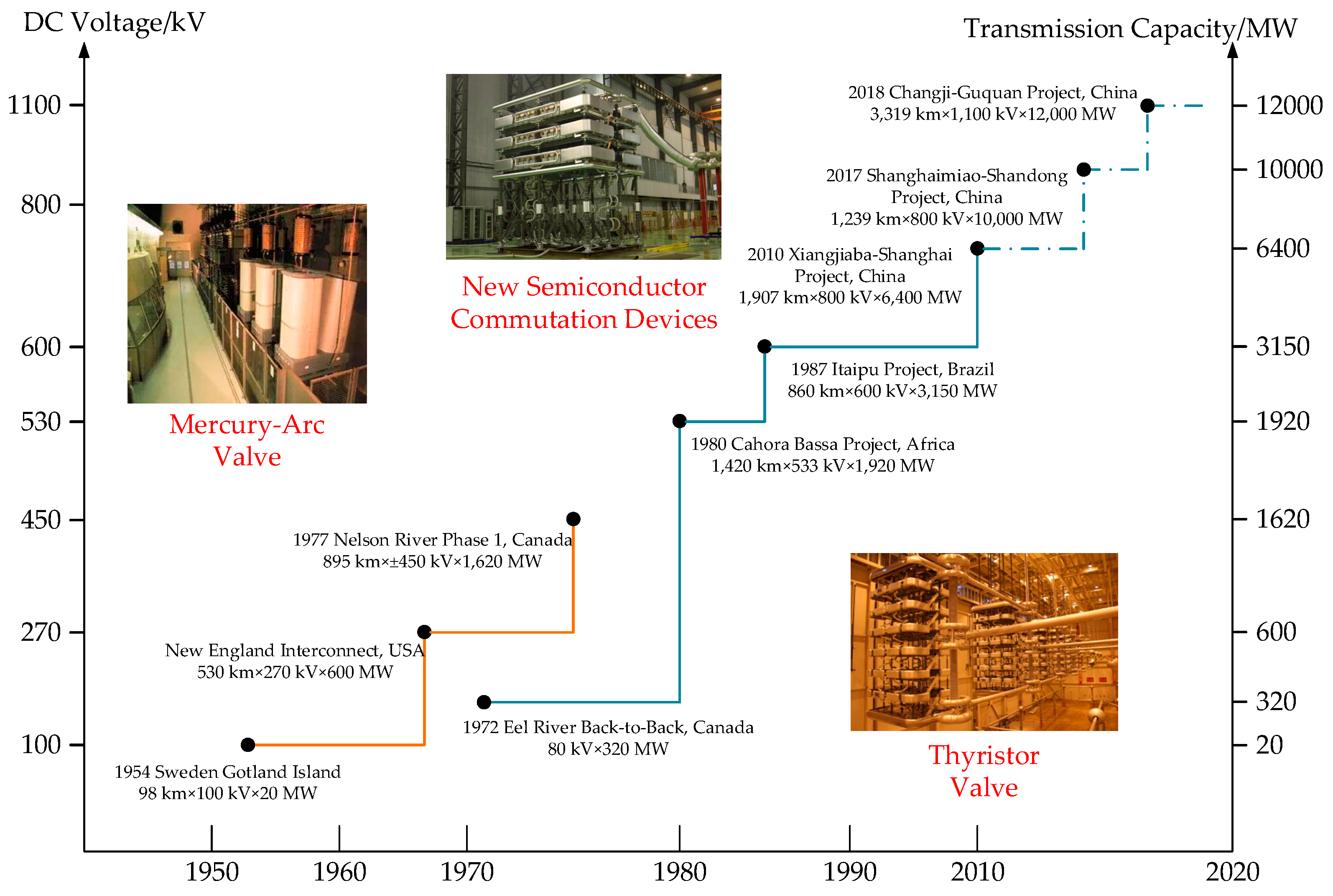
2.1. Development of DC Transmission Systems

The core equipment of a DC transmission system is the converter. The most important and critical component of the converter is the converter valve [14,15]. The condition of this component essentially determines the performance of the converter and the entire DC transmission system. Therefore, the development of converter-valve technology fundamentally represents the development of DC transmission technology [16]. Specifically, it can be divided into the following three periods, as shown in Figure 1.
The first phase is the mercury-arc valve commutation period. The mercury-arc valve commutation technology emerged around 1950. By 1977, a total of 12 DC transmission systems utilizing this technology had been officially built and put into use worldwide, with a transmission capacity of 5000 MW. Although the mercury-arc valve with gate control capability enabled the transmission of electrical energy through DC lines, its manufacturing technology was complex, costly, prone to faults, low in stability, and had high maintenance and repair costs.
The second phase is the thyristor valve period. After the 1970s, high-voltage, high-power thyristors were successfully developed. Compared to the mercury-arc valves of the previous phase, thyristor valves had significant performance advantages, primarily avoiding the drawbacks of mercury-arc valve commutation (i.e., reverse arc issues). In 1970, Sweden first constructed a DC transmission project based on thyristor valves on Gotland Island (with a voltage level of 50 kV and a rated transmission capacity of 10 MW). Thyristor valves did not have the reverse arc defect, were easy to install, and had simpler operation and maintenance after use [16,17].
The third phase is the period of new semiconductor commutation equipment. In the 1990s, insulated-gate bipolar transistors (IGBTs) emerged. In June 1999, the world’s first commercial DC transmission project was put into operation. This project was located on Gotland Island, Sweden, with a DC voltage of 80 kV, a DC current of 350A, a rated capacity of 54 MW, and a transmission distance of 70 km. Flexible DC transmission based on new semiconductor components is a new generation of DC transmission technology based on voltage source converters (VSCs), using fully controlled power devices like IGBT that can independently control the amplitude, frequency, and phase of the output voltage [18]. The converter topologies used in projects mainly include two-level, diode-clamped three-level, and modular multi-level converters (MMCs) [19]. In 2010, the world’s first flexible DC transmission project based on MMCs, the Trans Bay Cable project, was completed and put into operation. Early two-level and three-level flexible DC transmission projects were monopolized by foreign companies because of their unique power device series boosting technology. China independently carried out research on flexible DC transmission technology and commissioned the Shanghai Nanhui flexible DC transmission project in 2011, breaking the foreign monopoly on this technology. Subsequently, China’s flexible DC transmission technology developed rapidly, and in 2013, the world’s first multi-terminal flexible DC transmission project, the Nan’ao flexible DC transmission project, was put into operation. In 2020, the world’s first UHV flexible DC transmission project, the Kunliulong DC project, was completed and put into operation; in the same year, the world’s first DC grid project based on flexible DC transmission technology, the Zhangbei DC grid project, was completed and put into operation. Currently, the number of flexible DC transmission projects in operation worldwide has reached 51, with a total substation capacity exceeding 60 GW. However, although the devices currently used in flexible DC transmission, such as insulated-gate bipolar transistors (IGBTs) and injection-enhanced gate transistors (IEGTs), are capable of controllable shutdown, they cannot withstand reverse voltage. This significant performance difference from thyristors, along with limitations in capacity, cost, and loss, makes it difficult to replace thyristors in LCC DC systems [20,21,22].
To overcome the limitations of IGBTs in terms of capacity, voltage resistance, and current-carrying capability, new semiconductor commutation components such as integrated gate-commutated thyristors (IGCTs) and high-power silicon carbide components have been successfully developed [23]. These components have high voltage and large current-carrying capabilities, showing broad application prospects in DC transmission projects.

2.2. DC Transmission Project

DC transmission systems are an essential component of modern power systems that have made significant technological and application advancements. Through a series of innovative demonstration projects, DC transmission technology has not only achieved technical breakthroughs but also laid a solid foundation for the development of the global energy internet. Currently, China’s key DC transmission demonstration projects include LCC-type DC, hybrid DC, and IGCT-type DC projects [24]. These projects showcase the application of DC transmission technology from theory to practice and its contributions to improving transmission efficiency, enhancing system stability, and promoting technological innovation.

2.2.1. LCC-Type DC Transmission Project

The Changji-Guquan ±1100 kV UHVDC Transmission Project is the world’s highest voltage level, largest transmission capacity, longest transmission distance, and most technologically advanced UHV transmission project. It starts from the Zhundong (Changji) converter station in Xinjiang and ends at the Xuancheng (Guquan) converter station in Anhui. The Changji to Guquan project raises the voltage level from ±800 kV to ±1100 kV, increases the transmission capacity from 6.4 million kW to 12 million kW, and extends the economic transmission distance from 3000 to 5000 km. This project is a significant milestone in the State Grid’s continuous innovation in the UHV transmission field and serves as an important demonstration for the development of the global energy internet. However, the application of LCC technology also faces many challenges, such as reliance on large-scale reactive power compensation and complex harmonic control equipment, which increase the overall cost and operational complexity of the project [25,26].

2.2.2. Hybrid DC Transmission Project

The ±800 kV UHVDC Wudongde–Kunliulong hybrid DC transmission project, constructed by China Southern Power Grid Company, is the country’s first UHV multi-terminal DC demonstration project and the world’s first UHV hybrid DC project. Its topology is shown in Figure 2. The sending end is the Kunbei converter station, which uses a conventional LCC valve structure, while the receiving ends are the Liuzhou and Longmen stations, which adopt a MMC series topology.
The Wudongde–Kunliulong hybrid DC project, due to the use of fully controlled semiconductor devices, effectively avoids commutation failure issues and achieves decoupled control of active and reactive power, which is crucial for enhancing the safety and stability of multi-source DC input systems. Additionally, the use of a hybrid full-bridge and half-bridge modular multi-level converter (MMC) topology endows the system with the capability for automatic DC fault clearance and online valve group switching, thereby eliminating the need for DC circuit breakers [27]. However, this solution also has some disadvantages. On the one hand, the valve hall occupies an area 1.8 times that of traditional DC converter-valve halls, leading to higher construction costs for the converter station; on the other hand, the 4.5 kV/3000A IGBT devices used have higher losses and costs compared to traditional thyristor devices, with the cost being approximately four times that of thyristors for the same capacity [28,29,30].
The Baihetan UHVDC transmission project, as a key component of China’s “West-to-East Power Transmission” strategy, transmits power through two transmission lines with a total capacity of 18 million kW. The first line has a capacity of 8 million kW and utilizes a voltage level of ±800 kV. This project adopts an internationally innovative hybrid cascaded topology, effectively combining the economic benefits of traditional DC transmission systems with the regulatory flexibility of flexible DC transmission systems.
The hybrid cascaded system of the Baihetan UHVDC transmission project not only enhances the stability and efficiency of DC transmission but also achieves optimized power flow control by co-locating LCCs with multiple voltage source converters (VSCs) at the same site. The specific configuration includes a dual 12-pulse converter in series at the sending end and one LCC at the high-voltage end, with three VSCs at the low-voltage end at the receiving end [31]. This configuration strengthens the system’s performance in handling high transmission capacity and long-distance transmission, enabling effective management of transmission distances over 2000 km while maintaining high power supply stability and system reliability [32].

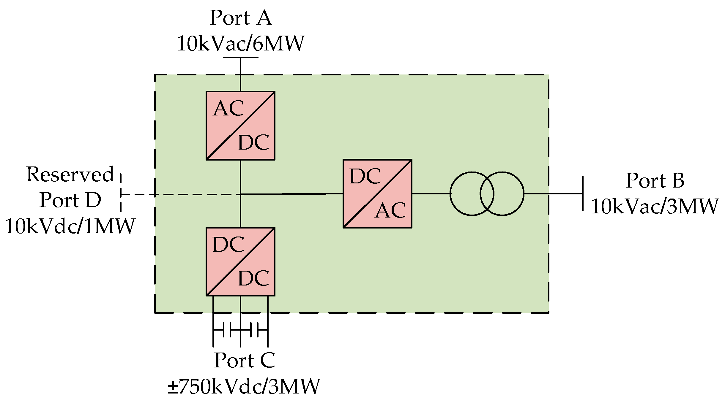
2.2.3. IGCT-Type DC Transmission Project

In the early operation phase in 2005, the Lingbao converter unit I primarily employed light-triggered converter valves based on Siemens technology and electrically triggered converter valves based on ABB technology. These converter valves utilized traditional silicon-controlled rectifier (SCR) technology, which is capable of handling high current and high voltage. However, in recent years, these components have shown issues with aging and maintenance difficulties. To address the limitations of traditional technology and the problems of system aging, IGCT (insulated gate-commutated thyristor) technology has been introduced in the upgrade and optimization of Lingbao converter unit I, bringing the following advantages [33]. Firstly, compared to traditional SCRs and IGBTs, IGCTs exhibit superior capability in handling high voltages and large currents, significantly enhancing the operational efficiency and system reliability of the converter unit. Secondly, the high-speed switching characteristics of IGCTs simplify control logic, allowing faster response times and more precise control, effectively reducing the operational complexity of the system. Thirdly, in the event of a fault, IGCTs can quickly identify and isolate the problem, offering excellent fault isolation and rapid recovery capabilities, which reduces system downtime and potential damage [34].
Additionally, IGCT technology is used in the Ulanqab Source–Grid–Load–Storage Integrated Power Router to enhance system access performance and operational flexibility. The overall architecture of the Ulanqab Source–Grid–Load–Storage Integrated Industrial Park Power Router based on the IGCT is shown in Figure 3. In this power router structure, Port A uses a MMC with fault clearance capability, with an AC rated voltage of 10 kV, a DC rated voltage of 10 kV (±5 kV), and a rated capacity of 6 MVA; Port B uses an isolated MMC, with an AC grid-side rated voltage of 10 kV, a DC rated voltage of 10 kV (±5 kV), and a rated capacity of 3 MVA; Port C uses a DCT based on DAB series-parallel connections, with a high-voltage side rated voltage of 10 kV (±5 kV), a low-voltage side DC voltage of ±750 V, and a rated capacity of 3 MW. The implementation of this project provides important validation for IGCT technology in practical grid applications, highlighting its critical role in high-voltage and high-capacity power applications.

2.3. Application Potential of the IGCT in DC Transmission

Since the 1990s, IGBTs have been widely used in voltage source converters, such as in the world’s first flexible DC transmission project based on MMCs, the Trans Bay Cable project. However, although the IGBT devices currently used in flexible DC transmission have controllable shutdown capabilities, they cannot withstand reverse voltage [13]. This results in significant performance differences compared to thyristors, and they are limited by capacity, cost, and losses, making it difficult to replace thyristors in LCC DC systems [35].
To overcome the limitations of IGBTs in terms of capacity, voltage resistance, and current-carrying capability, new semiconductor commutation components such as IGCTs and high-power silicon carbide elements have been successfully developed [15,36]. Compared to the IGBT, the IGCT has a lower on-state voltage drop, higher reliability, and lower manufacturing costs. It also boasts higher blocking voltage and current-carrying capabilities, making it very suitable for medium to high-voltage, high-capacity applications. In DC grids, critical equipment such as medium to high-voltage high-capacity AC-DC converters, DC transformers, and DC circuit breakers exhibit many new characteristics [19,20,37]. For example, modular multi-level AC-DC converters have extremely low switching frequencies, dual-active bridge DC transformers possess soft switching capabilities, and DC circuit breakers require only a single operation. These equipment designs effectively utilize the characteristics of the IGCT, significantly enhancing its application potential in DC grids. A comparative diagram of the cell structures of IGBTs and IGCTs is shown in Figure 4, and the comparison of the structural features and operational characteristics is listed in Table 1.
Figure 4 presents a schematic diagram of the typical cell structures of the IGCT and IGBT. In the design of IGBTs, a p+ emitter layer is added to the drain side of the N-channel MOSFET [37,38]. This allows the N-channel MOSFET and PNP transistor to coexist within the IGBT chip. The MOSFET provides a base drive current for the PNP transistor, which modulates the drift region’s conductivity, reducing the on-state resistance. However, the parasitic NPNP thyristor within the IGBT chip can be triggered under a high current, bypassing the MOSFET channel (latch-up effect). To mitigate this, a deep p+ base region is introduced to reduce the lateral resistance of the hole current, suppressing the thyristor’s activation. Modern IGBT chips also incorporate an n+ buffer layer between the n− drift region and the p+ emitter [13]. The high space charge density in the n+ buffer layer rapidly attenuates the electric field in the blocking state, preventing it from reaching the p+ emitter of the collector. This design reduces wafer thickness and conduction voltage drop compared to traditional designs without an n+ buffer layer.
Similarly, IGCT chips introduce an n+ buffer layer between the n− drift region and the anode p+ emitter to ensure blocking voltage while reducing conduction voltage drop. IGCT chips also use a transparent anode process similar to IGBT chips, allowing fine control of efficiency on the p+ emitter side. This design ensures high emission efficiency under low current, making the chip easy to turn on while suppressing high current emission efficiency [39]. This allows electrons in the n− drift region to quickly recombine at the metal electrode interface through the transparent anode during turn-off, reducing turn-off tail current and time and lowering turn-off loss. Although both IGBT and IGCT chips use structures like the n+ buffer layer and transparent collector (anode) on the PNP transistor side, the integration of the MOSFET gate structure makes the IGBT’s cell design more complex [22].
Since IGCT originated from thyristors and inherited most of their manufacturing processes, its current conduction principle, capability, and reliability are similar to those of thyristors, but its on-state loss is much lower than that of similarly controllable IGBT and IEGT [19]. Therefore, compared to the IGBT, the IGCT has greater advantages in terms of topology, voltage rating, manufacturing cost, and the degree of domestic production [23]. In the field of IGCT research and manufacturing, China has already achieved full domestic production capabilities for the IGCT. Research and production units such as Tsinghua University and CRRC Zhuzhou Times Semiconductor Co., Ltd., Zhuzhou, China, are actively promoting the research and application of converter-valve technology based on the IGCT. They have successfully developed engineering IGCT chips with an 8 kV voltage rating, 3 kA current-carrying capacity, and 5.5 kA shutdown capability. These units possess independent production capabilities and engineering application conditions for the electrical development, structural design, and operational testing of IGCT-type converter valves.
In addition, China has shown strong growth in the application of IGCT devices. The developed DC control protection platform has been successfully applied in the Tianguang DC control protection system renovation project, the Xiluodu double-circuit DC transmission project, the Qinghai-Tibet DC interconnection project, the Harbin-Zhengzhou UHVDC project, and the Jiuquan-Hunan UHVDC project. The application of IGCT technology in China has also extended to international projects, such as the renovation projects in the Philippines and the Belo Monte renovation project in Brazil. These projects have demonstrated the significant role of IGCT devices in improving valve control and DC control systems.

3. Efficient Simulation Modeling Technology for IGCT DC Transmission Systems

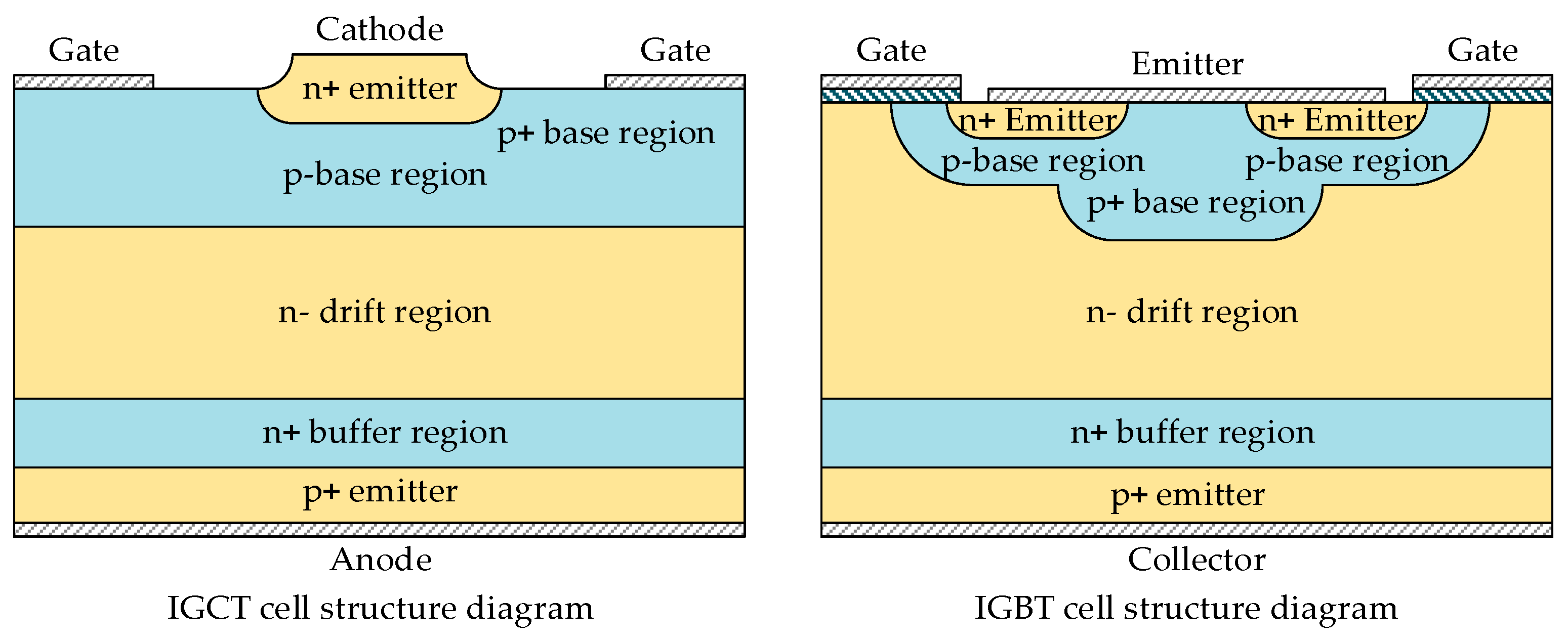
3.1. IGCT Modeling Technology

As a key device in high-voltage direct current (HVDC) transmission systems, the integrated gate-commutated thyristor (IGCT) possesses advantages such as low switching losses, fast response speed, and high thermal stability. Efficient simulation modeling technology for IGCT is essential for achieving performance optimization in HVDC systems.
Reference [20] verifies the effectiveness of the IGCT in suppressing commutation failures by constructing and analyzing a model on the CloudPSS platform. This study demonstrates the stability and reliability provided by IGCT during the commutation process. Reference [33] conducts a simulation study of a H-LCC based on the reverse blocking characteristics of the IGCT and thyristor using a physics-based compact model. It thoroughly analyzes the physical commutation characteristics and provides an effective strategy for mitigating commutation failure. This method helps achieve more accurate time-domain simulations in HVDC systems, thereby optimizing system performance. Combining LCC inverters with a hybrid scheme of full-bridge sub-modules based on the IGCT, Reference [40] shows better resistance to commutation failures, demonstrating significant advantages over existing schemes. By introducing new control strategies, the stability and reliability of the system are further enhanced. Reference [41] proposes an active shutdown control method for a hybrid commutated converter (HCC) based on fault prediction, using RB-IGCT technology to address commutation failure issues. This method significantly improves the operational safety of the system by predicting faults in advance and intervening proactively. Reference [42] suggests that using battery energy storage systems in HVDC systems can provide primary and secondary reserves, thereby stabilizing the grid and supporting the integration of large-scale offshore wind power. The specific topology and the use of bidirectional converters make this approach promising for high-voltage direct current transmission applications.

3.2. Efficient Modeling Technology for DC Transmission Systems

3.2.1. Efficient Modeling Technology Based on the Averaging Method

In the efficient modeling technology for DC transmission systems, the application of IGCT technology provides an effective approach to improving simulation accuracy and efficiency. Traditional averaging modeling techniques, such as state-space averaging (SSA) and generalized additive models (GAMs), although widely used for stability analysis and control strategy research in power systems, may not fully capture the dynamic characteristics of the IGCT and precisely express the complexity of its control logic when dealing with systems containing high-performance switching devices like IGCT. For instance, while SSA models can improve simulation efficiency and are suitable for controller design, they may be inadequate for high-precision switching dynamic analysis required to describe the IGCT’s performance characteristics.
As a device with high blocking voltage and large current-carrying capacity, the IGCT demands high accuracy in simulation models, particularly in simulating its fast-switching behavior and low on-state voltage drop. Therefore, improved modeling methods that can adapt to the characteristics of the IGCT have been proposed by researchers. For example, reference [43] introduces more detailed semiconductor models and optimized numerical computation techniques that can be used to simulate the application of the IGCT in modular multi-level converters (MMCs). This method significantly enhances the simulation efficiency of MMC models while retaining detailed information on module capacitor voltage fluctuations. Additionally, the application of the IGCT optimizes the dynamic analysis of DC circuit breakers and the simulation process of circulating current suppression strategies in multi-terminal DC transmission systems. Averaging techniques can better simulate these specific scenarios. Reference [44] proposes a new average-value model based on detailed numerical models, which does not alter the external characteristics of MMCs while ensuring simulation accuracy and significantly improving simulation speed. This model particularly emphasizes the energy fluctuations of MMC capacitor voltages and circulating current characteristics, making it suitable for circulating current suppression strategies, multi-terminal DC transmission, or DC grid simulation research. Considering IGCT’s key role in high-voltage DC transmission systems, especially in handling the speed and reliability of power electronic switches, IGCT modeling technology can be integrated with these techniques to better reflect IGCT’s dynamic characteristics and its interactions with the system. Reference [45] analyzes the dynamic process of arm capacitor voltage during the startup and DC fault periods of MMCs and proposes an improved equivalent electromagnetic transient simulation model. This model can accurately simulate the dynamic characteristics of total arm capacitor voltage under any operating condition, effectively enhancing the model’s practicality and predictive accuracy, and is expected to be used in simulations of DC systems containing IGCT.

3.2.2. Efficient Modeling Technology Based on the Dynamic Phasor Method

The essence of the dynamic phasor method is a time-varying Fourier series, which has a wider frequency band and can reflect more high-frequency characteristics of the system. In electromagnetic transient analysis, the dynamic phasor model can replace detailed time-domain models within a certain scope of study, and the complexity of the model can be adjusted according to the needs of the analysis [46]. Currently, scholars at home and abroad are conducting extensive modeling work for various power system devices, including MMCs [47,48], microgrids [49], HVDC [46,50,51], static synchronous compensators (STATCOM) [52], converters [53,54], flexible AC transmission systems (FACTS) [55], and others. These models are applied in power system transient analysis and protection design, subsynchronous oscillation analysis, and asymmetric fault analysis in power systems, achieving results comparable to detailed electromagnetic transient models.
Dynamic phasor modeling has been proven to effectively improve the simulation efficiency and accuracy of electrical device models containing power electronic components [47]. Particularly in IGCT application scenarios, since IGCT can handle higher voltages and currents, the advantage of the dynamic phasor method lies in its ability to selectively analyze the dominant frequencies in the system. This is especially important for simulating the performance of the IGCT in complex power grids. By adjusting the order of the Fourier series, the complexity and efficiency of the simulation can be tuned while maintaining model accuracy, catering to the specific requirements of the IGCT in high-performance DC transmission systems. The “scalability” of this method is significant for studying how IGCT affects system dynamic responses.
Dynamic phasor modeling not only has excellent interface characteristics but is also suitable for complex power systems, as demonstrated by the model proposed in reference [56]. This model adopts a method of separately modeling the control part, the internal electrical system of the modular multi-level converter (MMC), and the external electrical system, facilitating interfaces with external control systems and electrical systems. This method is also applicable to IGCT technology, particularly in the dynamic analysis of high-performance switching devices. Additionally, references [57,58] demonstrate the interface between dynamic phasor models and traditional electromechanical transient stability programs, enabling transient stability analysis of large-scale power systems. Dynamic phasor-electromagnetic transient hybrid simulation based on dynamic phasor models provides a higher acceleration ratio for transient stability analysis in ultra-large-scale power systems. Through this simulation, the rapid dynamic behavior of power electronic devices such as IGCT can be accurately simulated, optimizing the performance evaluation and control strategies of the entire system.

3.2.3. Efficient Modeling Technology Based on Parallel Processing

In network partition-based parallel algorithms, particularly when dealing with high-performance power electronic devices such as IGCTs, electromagnetic transient simulation processes fall under “system-level” parallelism. The complex control and fast-switching characteristics of IGCT devices require models to accurately reflect their electrical performance, making each device typically considered an indivisible entity in simulations. To enhance simulation efficiency, applying “component-level” parallel processing technology to these electrical devices becomes crucial. This technology optimizes the use of hardware, such as low-density and high-density parallel modeling, to effectively handle the dynamic behavior and complex topology of the IGCT, thereby improving the overall simulation speed and efficiency.
In low-density parallel modeling, partitioning techniques are used to segment the electrical device’s topology so that each part can be solved simultaneously within each simulation timestep. This method is suitable for multi-core computers or PC clusters. Although the methods proposed in references [59,60] do not directly study IGCT, they can still be applied to systems containing IGCTs. Reference [59] demonstrates the application of the ideal transformer partitioning method to MMCs, using advanced interpolation prediction to address delay issues in real-time simulation, and proposes an electromagnetic transient numerical model to avoid repeated generation of the admittance matrix, achieving ultra-real-time simulation. Reference [60] establishes a MMC model based on the state-space nodal method, supporting synchronous parallel computation of multiple MMC arms, thereby improving the accuracy and real-time performance of the simulation model. These methods can theoretically be applied to IGCT technology simulations to enhance simulation efficiency and accurately reflect IGCT’s dynamic behavior.
In high-density parallel modeling, particularly involving IGCT applications, references [61,62] provide GPU (graphics processing unit)-based methods that decompose the complex control and switching processes of electromagnetic transient simulations into numerous simple calculations that can be processed in parallel. These techniques are especially suitable for IGCT-driven PWM (pulse-width modulation) converter models because they need to handle high-speed switching actions and complex control logic. Additionally, references [63,64] describe FPGA (field-programmable gate array)-based models that offer real-time simulation solutiosns for power electronic components such as IGCT, optimizing the speed and accuracy of electromagnetic transient analysis. References [65,66] specifically show how Kirchhoff’s laws and equivalent transformations can be used to establish large-scale MMC models and achieve efficient parallel computation through FPGA, which is critical for systems containing multiple IGCT submodules. These parallelization technologies not only improve simulation efficiency but also enhance the model’s ability to handle the complex dynamics of the IGCT.

3.3. Efficient Simulation and Solution Technology for DC Transmission Systems

3.3.1. Parallelized Efficient Simulation and Solution Technology

Parallel computing technology has been widely applied to the electromagnetic transient simulation of large-scale complex power systems. Based on the “Diakoptics” technology [67,68], this method divides the power system into multiple subsystems, allowing each subsystem to be calculated in parallel on multiple computers or processors. Information is exchanged through communication technology, and the simulation results are integrated. Although this technology has been extensively studied, efficiently handling the switching process remains a significant challenge, especially in applications involving IGCT. Due to its requirements for switching speed and precise control, the development of parallel simulation technology is even more critical for IGCT. Currently, although parallel simulation technology is mainly applied to AC power systems, it also shows great potential for simulating DC or AC-DC hybrid systems containing IGCT, particularly for multi-rate parallel simulation.
Reference [69] propose an electromagnetic transient algorithm for partitioning and parallelizing AC-DC power systems. This algorithm, based on network partitioning, allows independent parallel computation of AC and DC networks containing IGCT by separately processing the AC and DC networks within the subnet. This method significantly improves the simulation efficiency of systems containing IGCT devices by using only the current of the tie lines between subnets rather than the current of the tie lines between internal AC and DC networks. Reference [70] uses MATE (multi-area Thevenin equivalent) technology to treat switching elements (such as IGCTs) as sub-connection lines, eliminating these sub-connection line currents to partition the subnet, thereby reducing the computational burden of electromagnetic transients. This is particularly important for complex systems involving IGCT switches. This method simplifies the computation process while maintaining network topology consistency, making it particularly suitable for large-scale simulations of power systems containing IGCT.
Reference [71] combines latency technology with the multi-rate concept to significantly improve the efficiency of electromagnetic transient simulation [72]. This method is particularly suitable for power systems containing IGCT because the high-speed switching characteristics of the IGCT require the simulation algorithm to accurately capture rapid dynamics. References [73,74] propose a multi-rate electromagnetic transient simulation based on latency technology, optimizing the solution process of slow dynamic systems and fully utilizing the results of fast dynamic systems (such as IGCT operations), thereby improving the accuracy and efficiency of the simulation. Reference [75] utilizes fully implicit integration and interpolation methods and achieves parallelization of the simulation algorithm through transmission line partitioning, proposing a parallel multi-rate electromagnetic transient simulation algorithm suitable for power systems containing IGCT.

3.3.2. Efficient Simulation and Solution Technology Based on CPU-GPU Co-Processing

The central processing unit (CPU) is suitable for handling computation problems with low parallelism, clear data locality, and complex operations, such as forming the nodal admittance matrix, calculating Norton equivalent currents, and solving nodal voltage equations in electromagnetic transient simulations. These steps involve a large number of branching structures, making them suitable for CPU processing. Conversely, the GPU is suitable for handling computation problems with high computational intensity and high parallelism, which can optimize the simulation process of the IGCT switching actions. On an electromagnetic transient simulation platform based on CPU-GPU co-processing, such as NVIDIA’s CUDA (Compute Unified Device Architecture) shown in Figure 5, the GPU can act as a co-processor to the CPU, handling parallel computation tasks, thereby effectively improving the efficiency and accuracy of IGCT-related computations.
Reference [76] proposes a CPU-GPU co-simulation architecture, specifically using the CULA linear algebra library developed by EM Photonics on the GPU to invert the nodal admittance matrix for solving the nodal voltage equations. This method is particularly suitable for large-scale AC-DC hybrid system simulations, including efficient IGCT simulations. However, the main drawback of this approach is the long data transfer time between the CPU and GPU. To address this, reference [62] proposes a node mapping structure (NMS) based on block-node adjustment. By concentrating the admittance matrix elements into the diagonal region and dividing the large system into multiple smaller systems, this method effectively reduces data transfer time, thereby optimizing the simulation efficiency of systems containing IGCT.

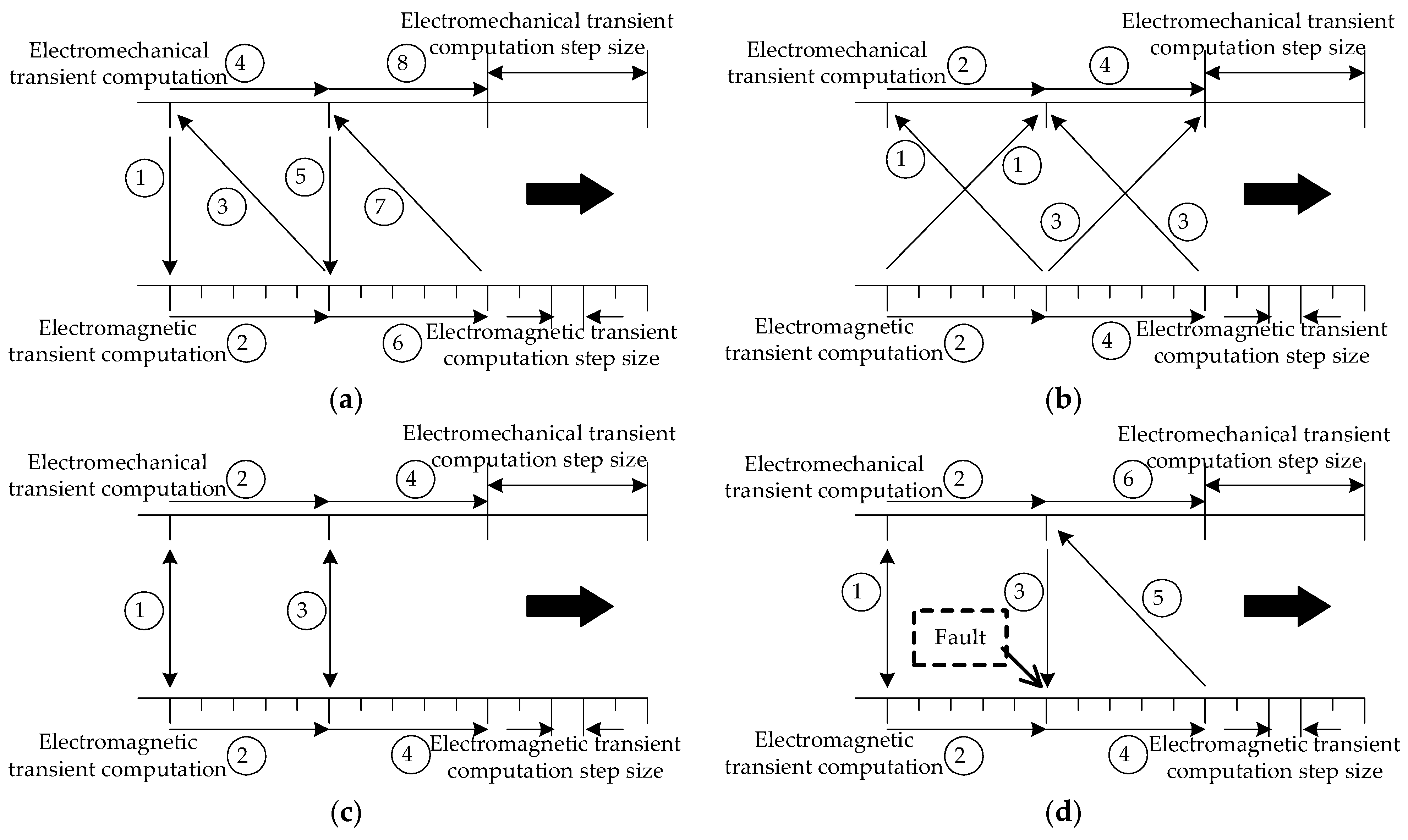
3.3.3. Efficient Simulation and Solution Technology Based on Electromechanical-Electromagnetic Hybrid Mode

In hybrid simulation, the data interaction between the electromechanical transient and electromagnetic transient sides typically occurs at specific time intervals. The main data interaction timing methods currently include serial data interaction [77,78,79], parallel data interaction [80], and iterative data interaction. The interaction sequence of the four interfaces is shown in Figure 6. These interaction methods are particularly critical for the simulation of fast-switching devices such as IGCT. In serial interaction, the handover errors at the moments of fault occurrence and clearance are more pronounced. To address this issue, references [81,82] adopt a combination of serial and parallel methods, using parallel interaction to increase speed during steady-state operation and serial interaction to improve accuracy during changes in network structure. Reference [83], based on the characteristics of iterative solution methods, uses extrapolation of existing results during the electromagnetic side calculations and applies them to each iteration on the electromechanical side. As the number of iterations on the electromechanical side increases, the accuracy of the extrapolated values on the electromagnetic side also improves. This improved parallel method eliminates the need for synchronization waiting processes, enhancing simulation accuracy. Optimizing the timing of hybrid simulation interface interactions is a key focus of future research to meet the requirements for both accuracy and efficiency.

4. Control Technology for IGCT-Based DC Transmission Systems

4.1. Control Technology of New Commutation Techniques for Mitigating Commutation Failures

In high-voltage direct current (HVDC) transmission systems, commutation failure is a critical issue affecting system stability and reliability. With the rapid development of power systems and technological advancements, various research institutions and enterprises have proposed numerous control strategies to prevent and address commutation failures. These control methods play a crucial role in enhancing system operational safety and response speed. Although traditional control techniques can still meet basic needs in some scenarios, their effectiveness may be limited under more complex or extreme conditions. Therefore, developing new commutation techniques and corresponding control strategies is of significant theoretical and practical importance for improving overall system performance and coping with extreme operating conditions.
Reference [84] proposes a commutation failure prediction control method based on the real-time measurement of three-phase AC voltages. This method uses real-time voltage data to predict potential commutation failures and initiate preventive measures to reduce system instability caused by such failures. By utilizing the traditional line-commutated converter (LCC) topology, this method enhances data monitoring and analysis to provide early warnings of potential commutation issues. Reference [85] improves upon the method in [84] by increasing the sensitivity of the algorithm to detect potential commutation failures earlier. The improved method refines the data processing flow and optimizes algorithm logic, thereby enhancing prediction accuracy and response speed and providing system operators with more timely intervention opportunities. Reference [86] proposes a direct measurement-based method for predicting and detecting commutation failures. Unlike traditional model-based predictions, this method extracts key indicators directly from actual system operation data, enabling more real-time and intuitive fault prediction. This method is particularly suitable for complex or rapidly changing grid environments and can effectively improve the detection rate of commutation failures. Reference [87] explores a commutation failure detection method based on the characteristics of arm current variations. By analyzing the current variation patterns in the arm, this method can accurately identify impending commutation failures, allowing the system to adjust control strategies to prevent faults. References [88,89] investigate LCC topologies with auxiliary capacitors on the AC side and arm side. While these studies provide new converter design schemes, they do not propose corresponding control strategies, which limits their effectiveness in practical applications. References [90,91] study different Voltage Dependent Current Order Limiter (VDCOL) methods in multi-terminal DC systems. These methods enhance the stability and adaptability of DC systems in the face of commutation failures by adjusting the system’s voltage control strategies. Reference [92] reduces the impact of a single fault point on the entire system by adjusting the power output of different DC lines. This strategy increases system redundancy and robustness by diversifying risk. Reference [93] investigates collaborative control by adjusting the output of commutation failure prevention (CFPREV). This method aims to enhance the coordination of control strategies, improving system response speed and recovery capability in the event of a fault.
HVDC systems based on integrated gate-commutated thyristors (IGCTs) exhibit significant advantages in resisting commutation failures. As a fully controllable switching device, the IGCT can effectively suppress commutation failures in HVDC systems, ensuring safe and stable grid operation. Reference [20] studies the application of the IGCT in HVDC systems, showing that the IGCT can effectively suppress commutation failures through comprehensive control of switching actions. This study verifies through time-frequency domain analysis that the IGCT has minimal impact on system stability under high-frequency and low-frequency conditions. Reference [94] proposes a control strategy for rapidly reducing DC power to mitigate the risk of continuous commutation failures in HVDC systems under weak AC conditions. The effectiveness of this strategy is validated in actual HVDC transmission systems, where quick adjustments of DC power enhance the system’s recovery capability. By incorporating the IGCT and advanced control strategies, HVDC systems have significantly improved in resisting commutation failures. These technologies and strategies not only enhance system operational reliability but also provide important references for the design and optimization of future HVDC systems.

4.2. Stability Control and Protection Technology for IGCT-Based DC Transmission

In research and engineering applications, the use of insulated-gate bipolar transistors (IGCTs) has primarily focused on medium-voltage, low-capacity scenarios. In December 2018, the world’s first cross-clamp converter valve based on the IGCT-Plus was successfully applied in the Zhuhai Tangjiawan three-terminal flexible DC distribution network project, which is one of the largest capacity flexible DC distribution networks in the world. This marks the practical application achievement of IGCT technology in the field of flexible DC distribution, highlighting its potential and reliability in medium voltage applications.
Although IGCT has performed well in medium voltage, low-capacity applications, its application in high-voltage DC transmission systems remains unexplored. In 2021, CRRC Zhuzhou Institute led research on the IGCT as a new fully controlled switching device, focusing primarily on the IGCT design, turn-on and turn-off characteristics, and valve body parameter optimization. However, these studies did not address the adaptation of DC control protection functions corresponding to IGCT, nor did they explore the coordination of valve control design and the integration of valve control with DC control protection in depth.
Reference [95] provides a conceptual description and comparison of using IGCT as the main topology for high-voltage DC transmission but does not involve specific research on DC control protection functions. Currently, high-voltage and ultra-high-voltage DC transmission systems operating domestically mainly use thyristors as converter devices, and research on DC control protection functions still focuses on line-commutated converter (LCC)-based systems. Reference [96] derives the quantitative relationship between the negative sequence component of commutation voltage and the phase-locked loop and proposes a transient overvoltage suppression scheme, studying commutation failure prevention control strategies and their parameter tuning methods. These studies indicate that while there is extensive research and accumulated knowledge on traditional and ultra-high-voltage DC transmission issues, there is a lack of in-depth analysis of DC control protection strategies and their impacts when applying new converter devices such as IGCT.
As a converter station is about to undergo a comprehensive renovation of its DC control protection equipment, research on the coordination between DC control protection systems and IGCT valve control is becoming increasingly urgent. Future research needs to further explore how to utilize the turn-off characteristics of the IGCT to address commutation failure issues caused by weak AC grids and how to integrate IGCT technology with the design and operation of DC control protection systems.

4.3. Technology for Enhancing Receiving Capacity of IGCT-Based DC Transmission Systems

In the field of research on enhancing the receiving capacity and stability control methods of DC grids, extensive studies have been conducted. These studies primarily focus on how to improve system transient stability through fast power control techniques in DC systems. In terms of enhancing the receiving capacity of DC grids, current research is concentrated on utilizing fast power control to improve transient stability. Open-loop feedforward control strategies rely on preset control logic to adjust output based on the system’s predetermined response. While this approach is simple and easy to implement, it may lack flexibility or effectiveness under complex or nonlinear fault conditions due to the absence of real-time system state feedback. In contrast, closed-loop feedback control strategies continuously monitor system status and adjust control outputs based on real-time data, thereby improving control accuracy and system adaptability.
Reference [97] proposes a coordinated control strategy that combines dynamic area control error (ACE) with flexible DC emergency power support. This strategy evaluates the effectiveness of the control scheme by simulating actual grid data and aims to achieve a more optimized grid operating state. By finely tuning emergency power support, it enhances the transient stability and reliability of the system. Reference [98] analyzes the response characteristics, control costs, and transient security margins of various control measures based on the system’s transient security characteristics and control requirements. Consequently, the study proposes a decision-making method for coordinated stability control of emergency power by integrating multiple types of control measures. This method aims to provide a comprehensive solution to improve the overall stability and efficiency of the system.
The emergency DC power support protocol (EDCSP) has been practically tested in several large-scale AC-DC transmission projects, such as the submarine DC system from Sweden to Finland and the Rihand-Delhi DC system in India. Test results show that EDCSP not only improves the transient stability of the system but also effectively increases the power transmission capacity of parallel AC lines. These cases highlight the practical value of the EDCSP in engineering practice and its significant impact on system performance.
With the integration of IGCT-based DC technology, existing DC systems need to effectively coordinate the stability control strategies of conventional DC and IGCT-based DC systems. The goal of this coordinated control strategy is to maximize the receiving capacity and stable operation of the DC system, ensuring that the DC system maintains efficient and stable performance under various operating conditions.

5. Future Research Prospects

(1)
Full Electromagnetic Transient Simulation Technology for DC Grids Containing IGCT-Based DC, Conventional DC, and Sending-Receiving End AC-DC Hybrid Networks
Integrating DC electromagnetic transient models into a large power grid to form a full electromagnetic transient model of an AC-DC hybrid network is an effective means of studying the mutual impacts of AC and DC after faults, conducting fault inversion, and exploring DC operating mechanisms. The foundation for constructing a full electromagnetic transient model of an AC-DC hybrid large power grid is DC entity modeling. It is necessary to develop high-precision general control protection models that match the functions of actual control protection systems and propose refined valve control system modeling methods to accurately simulate the operating characteristics of IGCT-based DC.
Considering the lack of reference experience in simulation data and tools for simulating large power grids containing DC groups, future research will focus on how to construct full electromagnetic transient models of DC groups containing IGCT-based DC, conventional DC, and AC-DC hybrid large power grids at the sending and receiving ends. This research will promote the development of grid simulation technology, provide practical support for grid design and optimization, and is expected to drive broader industry applications and technological innovation.
(2)
Control Protection Strategies Adapted to IGCT Converter Valves
Control protection strategies for DC determine whether a DC transmission system can fully support grid regulation. Under the background of IGCT converter valves, DC control protection strategies will exhibit different characteristics from conventional LCC converter valves. Balancing steady-state operation and maintaining stable DC operation in the event of faults or disturbances in the external grid will be a key focus of future research. Additionally, analyzing methods to improve commutation failure issues under IGCT converter valves is crucial. Furthermore, since conventional LCC valves consume a large amount of reactive power during operation, future research will explore whether the application of IGCT converter valves and adjustments to DC control protection strategies can reduce reactive power consumption, thus improving the economic efficiency of DC operation.
(3)
Voltage Stability Coordination Control and Methods to Enhance Receiving Capacity of DC Groups with IGCT-Based DC
Power systems containing IGCT-based DC and conventional DC exhibit tightly coupled transient voltage characteristics, complex fault evolution mechanisms, and diverse control and regulation methods. It is urgent to establish a voltage transient characteristic assessment system for grids with IGCT-based DC integration and perform quantitative characterization. Meanwhile, after integrating IGCT-based DC, effective coordination of stability control measures between conventional DC and IGCT-based DC is required to maximize the receiving capacity and stable operation capability of the DC system. Therefore, quantitatively studying the interactive impact mechanism of voltage stability between the sending and receiving end AC grids and proposing multi-resource coordinated voltage stability control technology, along with multi-DC modulation techniques aimed at enhancing the stable receiving capacity of DC groups, are key areas for future research.

6. Conclusions

The modeling and control of IGCT-based DC transmission systems have been a key research topic for scholars both domestically and internationally. This paper summarizes and concludes the key technologies in the modeling and control of IGCT-based DC transmission systems from four aspects: the development of DC transmission systems and the potential application of the IGCT, efficient simulation modeling technology for IGCT-based DC transmission systems, control technology for IGCT-based DC transmission systems, and future research prospects. The conclusions are as follows:
(1)
Efficient simulation modeling technology for IGCT-based DC transmission systems is crucial for optimizing HVDC system performance. By adopting advanced modeling techniques, including the averaging method, dynamic phasor method, and parallel processing, the accuracy and efficiency of simulations can be significantly improved, providing stable and reliable simulation support for DC transmission systems. Additionally, simulation and solution technologies based on CPU-GPU co-processing and electromechanical-electromagnetic hybrid modes further optimize the efficiency and accuracy of IGCT-related calculations. The application and development of these technologies provide strong technical support for the design and operation of high-performance DC transmission systems.
(2)
By adopting new control strategies and efficient fault prediction methods, IGCT-based DC transmission systems can effectively prevent and address commutation failures, thereby enhancing the safe operation of the power grid. Moreover, by combining dynamic area control and emergency power support strategies, the IGCT not only improves the transient stability of the system but also increases the power transmission capacity of the grid. The application and development of these technologies confirm the potential of the IGCT in traditional and ultra-high-voltage DC transmission systems, providing valuable references for the design and optimization of future DC transmission systems.
(3)
Future research will focus on developing full electromagnetic transient models that match IGCT-based and conventional DC transmission systems to accurately simulate the electromagnetic response of DC systems and optimize DC control protection strategies. The control protection strategies suitable for IGCT converter valves aim to enhance the stability and economic efficiency of DC systems under fault conditions and external disturbances. Future research will strive to develop voltage stability coordination control technology and multi-DC modulation technology to enhance the receiving capacity of DC groups and overall system stability, promoting grid design, optimization, and technological innovation.

Author Contributions

Conceptualization, D.Y.; methodology, Z.Y.; software, J.K.; validation, D.Y.; formal analysis, Q.L.; investigation, Z.G.; resources, X.W.; data curation, D.Z.; writing—original draft preparation, Q.L.; writing—review and editing, C.L.; visualization, D.Z.; supervision, T.L.; project administration, K.L.; funding acquisition, C.L. All authors have read and agreed to the published version of the manuscript.

Funding

This research is supported by Science and technology projects of State Grid Corporation of China (5100-202324426A-3-2-ZN).

Data Availability Statement

Not applicable.

Conflicts of Interest

Degui Yao, Di Zhang, Qiang Li, Chenghao Li and Ze Gao were employed by Electric Power Research Institute of State Grid Henan Electric Power Company; Kai Liu was employed by NR Electric Co., Ltd.; Jianshuang Kang was employed by DC Technology Center of State Grid Corporation of China; Tingting Li was employed by State Grid Smart Grid Research Institute Co., Ltd. The remaining authors declare that the research was conducted in the absence of any commercial or financial relationships that could be construed as a potential conflict of interest.

References

  1. Ai, H.; Fang, Y.; Chen, D.; Li, P.; Wu, J.; Wang, Q.; Xe, C.L. Study on stability system and control strategy in Jinbei-Nanjing HVDC project. Power Syst. Prot. Control 2018, 46, 118–125. [Google Scholar]
  2. Guo, H.; Wu, Y.; Chen, D.; Wang, Y.; Zhou, X. Voltage balance control of valves in hierarchical connection mode for ximeng-Taizhou UHVDC system. Autom. Electr. Power Syst. 2019, 43, 176–181. [Google Scholar]
  3. Zhou, X.; Chen, S.; Lu, Z.; Huang, Y.; Zhao, Q. Technology Features of the New Generation Power System in China. Proc. CSEE 2018, 38, 1893–1904. [Google Scholar]
  4. Tang, Y.; Zheng, C. Review on Influencing Factors of Commutation Failure in HVDC Systems. Proc. CSEE 2019, 39, 499–513. [Google Scholar]
  5. Zhou, B.; Hong, C.; Rao, H.; Zhao, Y. Influence of Simultaneous Commutation Failure of Guangdong Multiple HVDC on Power System Secure Operation. South. Power Syst. Technol. 2017, 11, 18–24. [Google Scholar]
  6. Zhu, H.; Hao, L.; He, J.; Guo, Z.; Chen, Z. Mechanism analysis of commutation failure caused by fault of HVDC sending end AC system. Trans. China Electrotech. Soc. 2023, 38, 4465–4478. [Google Scholar]
  7. Wang, J.; Zheng, R.; Fu, C.; Wu, Q. A method based on constant reactive power control of inverter to suppress the subsequent commutation failure in HVDC system. Trans. China Electrotech. Soc. 2023, 38, 4672–4682. [Google Scholar]
  8. Guo, C.; Liu, Y.; Zhao, C.; Wei, X.; Xu, W. Power component fault detection method and improved current order limiter control for commutation failure mitigation in HVDC. IEEE Trans. Power Deliv. 2015, 30, 1585–1593. [Google Scholar] [CrossRef]
  9. Son, H.I.; Kim, H.M. An algorithm for effective mitigation of commutation failure in high-voltage direct-current systems. IEEE Trans. Power Deliv. 2016, 31, 1437–1446. [Google Scholar] [CrossRef]
  10. Su, C.; Yin, C.; Li, F. Commutation failure analysis in HVDC transmission system based on DC current dynamic rise. Electr. Power Autom. Equip. 2023, 43, 204–209. [Google Scholar]
  11. Li, S.; Li, Y.; Tao, D.; Liu, Y.; Yang, W.; Wu, Z. Improved suppression measure to commutation failure at non-fault layer of UHVDC under hierarchical connection mode. Power Syst. Technol. 2022, 46, 4502–4514. [Google Scholar]
  12. Zeng, R.; Zhao, B.; Yu, Z.; Song, Q.; Huang, Y.; Chen, Z. Development and Prospect of IGCT Power Device in DC Grid. Proc. CSEE 2018, 38, 4307–4317. [Google Scholar]
  13. Zhou, W.; Zeng, R.; Zhao, B.; Chen, Z.; Liu, J.; Bai, R. Comparative Analysis of Large-capacity Fully-controlled Press-pack IGBT and IGCT: Principle, Structure, Characteristics and Application. Proc. CSEE 2022, 42, 2940–2956. [Google Scholar]
  14. Guo, Z.; Pu, Y.; Zhong, Q.; Lu, Y.; Zhang, M. The Research of Cooperative Control Strategy for Suppressing LCC-HVDC Commutation Failure. In Proceedings of the 2022 4th International Conference on Smart Power & Internet Energy Systems, Beijing, China, 27–30 October 2022. [Google Scholar]
  15. Xu, C.; Yu, Z.; Zhao, B.; Chen, Z.; Wang, Z.; Ren, C.; Zeng, R. A Novel Hybrid Line Commutated Converter Based on IGCT to Mitigate Commutation Failure for High-Power HVdc Application. IEEE Trans. Power Electron. 2022, 37, 4931–4936. [Google Scholar] [CrossRef]
  16. Lou, Y.; Wang, S.; Zhang, L.; Qu, L.; Wang, J.; Zi, Z.; Li, L.; Wang, Z.; Gao, Q.; Yu, Z.; et al. Mechanism and Analysis of HCC to Suppress DC Commutation Failure. In Proceedings of the 2023 IEEE 7th Conference on Energy Internet and Energy System Integration, Hangzhou, China, 15–18 December 2023. [Google Scholar]
  17. Wang, H.; Huyang, M.; Dong, Q.; Chao, W.; Shi, S.; Dong, X. A Thyristor-Controlled Superconducting Current Limiting Module on Mitigation of Commutation Failure in LCC-Based HVDC Systems. In Proceedings of the 2023 IEEE International Conference on Advanced Power System Automation and Protection, Xuchang, China, 8–12 October 2023. [Google Scholar]
  18. Deng, L.; Zhou, X.; Hong, L.; Yin, H.; Zhu, R. A Damping-Controllable-Commutated Converter for Mitigating Commutation Failure of LCC-HVDC. IEEE Trans. Power Deliv. 2023, 38, 4371–4383. [Google Scholar] [CrossRef]
  19. Vemulapati, U.; Johannesson, D.; Wikström, T.; Stiasny, T.; Corvace, C.; Winter, C. High-Voltage (8.5 kV) Asymmetric IGCT for MVD and HVDC Applications. In Proceedings of the 2023 11th International Conference on Power Electronics and ECCE Asia (ICPE 2023—ECCE Asia), Jeju Island, Republic of Korea, 22–25 May 2023. [Google Scholar]
  20. Li, Y.; Cui, Z.; Sun, R.; Guo, H.; Zhang, D.; Li, C. Time-Frequency Domain Analysis of IGCT-based HVDC System on CloudPSS Platform. IEEE Trans. Ind. Electron. 2023, 70, 12345–12356. [Google Scholar]
  21. Zhou, W.; Zhao, B.; Liu, J.; Chen, Z.; Tang, X.; Yu, Z.; Wu, J.; Zeng, R. Systematic Analysis and Characterization of Extreme Failure for IGCT in MMC-HVdc System—Part I: Device Structure, Explosion Characteristics, and Optimization. IEEE Trans. Power Electron. 2022, 37, 8076–8086. [Google Scholar] [CrossRef]
  22. Zhou, W.; Liu, J.; Zhao, B.; Liu, J.; Chen, Z.; Tang, X.; Yu, Z.; Zeng, R. Comprehensive Analysis, Design, and Experiment of Shoot-Through Faults in MMC Based on IGCT for VSC-HVDC. IEEE Trans. Power Electron. 2021, 36, 6241–6250. [Google Scholar]
  23. Zhou, W.; Zhao, B.; Lou, Y.; Sun, X.; Liu, Q.; Bai, R.; Liu, J.; Chen, Z.; Yu, Z.; Zeng, R. Current Oscillation Phenomenon of MMC Based on IGCT and Fast Recovery Diode with High Surge Current Capability for HVDC Application. IEEE Trans. Power Electron. 2021, 36, 6218–6222. [Google Scholar] [CrossRef]
  24. Lan, T.; Sun, H.; Zhong, W.; Jing, Y.; Zhao, B.; Xu, J. LCC-HVDC’s Systematical Impact on Voltage Stability: Theoretical Analysis and a Practical Case Study. IEEE Trans. Power Syst. 2023, 38, 1663–1675. [Google Scholar] [CrossRef]
  25. Gao, C.; Yang, J.; He, Z.; Tang, G.; Zhang, J.; Li, T.; He, D. Novel Controllable-Line-Commutated Converter for Eliminating Commutation Failures of LCC-HVDC System. IEEE Trans. Power Deliv. 2023, 38, 255–267. [Google Scholar] [CrossRef]
  26. Li, D.; Gao, Y.; Sun, M. A General Self-Adaptive DC Current Control of LCC-HVDC for Eliminating Subsequent Commutation Failure. IEEE Trans. Power Deliv. 2023, 38, 2232–2235. [Google Scholar] [CrossRef]
  27. Li, J.; Zhu, B.; Guo, Y.; Liang, Z.; Wu, H.; Liu, H. The Simulation of Kunliulong Flexible DC Project with Single Station Operation and out of Operation. In Proceedings of the 2021 IEEE/IAS Industrial and Commercial Power System Asia (I&CPS Asia), Chengdu, China, 18–21 July 2021. [Google Scholar]
  28. Wang, Y.; Li, Z. Decision-Making Support Method for Control Strategies of Hybrid Cascaded MTDC System. In Proceedings of the 2023 IEEE/IAS Industrial and Commercial Power System Asia (I&CPS Asia), Chongqing, China, 14–16 July 2023. [Google Scholar]
  29. Liu, Y.; Luo, G.; Yang, Y.; Zhang, X.; Li, D.; Yang, L. Adaptability Analysis of Traveling Wave Protection in Multi-terminal Hybrid DC Transmission Lines. In Proceedings of the 2020 4th International Conference on HVDC (HVDC), Xi’an, China, 6–9 November 2020. [Google Scholar]
  30. Rao, H.; Zhou, Y.; Zou, C.; Xu, S.; Li, Y.; Yang, L.; Huang, W. Design Aspects of Hybrid HVDC System. CSEE J. Power Energy Syst. 2021, 7, 644–653. [Google Scholar]
  31. Gu, J.; Hu, X.; Zheng, W.; Cao, M.; Zou, G. Analysis and Suppression of DC bias in Baihetan-Zhejiang UHVDC Transmission Project. In Proceedings of the 2022 4th International Conference on Intelligent Control: Measurement and Signal Processing (ICMSP), Hangzhou, China, 8–10 July 2022. [Google Scholar]
  32. Tao, Y.; Lin, J.; Zheng, J.; Bin, Z.; Wang, C.; Kong, X. Research on Analysis and Improvement Strategy on Overcurrent After LCC Blocking in Hybrid Cascaded UHVDC Transmission System. In Proceedings of the 2023 International Conference on Power System Technology (PowerCon), Jinan, China, 21–22 September 2023. [Google Scholar]
  33. Yu, Z.; Wang, Z.; Xu, C.; Zhou, X.; Chen, Z.; Ren, C.; Zeng, R. Comprehensive Physical Commutation Characteristic Analysis and Test of Hybrid Line Commutated Converter Based on Physics Compact Model of IGCT. IEEE Trans. Power Electron. 2023, 38, 1924–1934. [Google Scholar] [CrossRef]
  34. Zhao, X.; Liu, W.; Li, X.; Pang, S.; Wang, M.; Zhang, H. Research on Topology of Medium Voltage Hybrid DC Circuit Breaker Based on IGCT. In Proceedings of the 2020 4th International Conference on HVDC (HVDC), Xi’an, China, 6–9 November 2020. [Google Scholar]
  35. Shen, X.; Wang, Y.; Li, M.; Wu, F.; Ma, W. Line Commutated Converter Based on Integrated Gate Commutated Thyristor. In Proceedings of the 2023 IEEE 7th Conference on Energy Internet and Energy System Integration (EI2), Hangzhou, China, 15–18 December 2023. [Google Scholar]
  36. Guedon, D.; Ladoux, P.; Sanchez, S.; Cornet, S. High Voltage IGCTs for HVDC Converter-Stations. In Proceedings of the 2021 AEIT HVDC International Conference (AEIT HVDC), Genoa, Italy, 27–28 May 2021. [Google Scholar]
  37. Zeng, H.; Pan, X.; Chen, F.; Chen, Y.; Zou, P. Power Supply System Design for IGCT Gate Unit in Series Application. In Proceedings of the 2023 IEEE 7th Conference on Energy Internet and Energy System Integration (EI2), Hangzhou, China, 15–18 December 2023. [Google Scholar]
  38. Xu, C.; Yu, Z.; Zhao, B.; Wang, Z.; Chen, Z.; Zeng, R. Ultra-Low Reactive Power Operation and Control Strategy of Hybrid Line Commutated Converter Based on IGCT for HVdc Application. IEEE Trans. Ind. Electron. 2023, 70, 12926–12932. [Google Scholar] [CrossRef]
  39. Xu, C.; Yu, Z.; Zhao, B.; Chen, Z.; Wang, Z.; Ren, C.; Zeng, R. Hybrid Line Commutated Converter With Fast Commutation Characteristic Based on IGCT for HVDC Application: Topology, Design Methodology, and Experiments. IEEE Trans. Power Electron. 2023, 38, 4668–4679. [Google Scholar] [CrossRef]
  40. Liu, Y.; Zeng, X.; Luo, Y.; Qu, H. A modified control strategy for LCC with IGCT-based full-bridge submodules to solve the commutation failure issues. IET Power Electron. 2023, 16, 1234–1245. [Google Scholar] [CrossRef]
  41. Ma, Y.; Yuan, Z.; Lou, Y.; Wang, Z.; Wang, J.; Zhang, L.; Gao, Q.; Huang, Z.; Li, L. Turn-off Control Method of the Hybrid Commutated Converter Based on Fault Prediction. IEEE Trans. Ind. Electron. 2023, 70, 7890–7900. [Google Scholar]
  42. Hellesnes, M.N. Use of Battery Energy Storage for Power Balancing in a Large-Scale HVDC Connected Wind Power Plant. J. Renew. Sustain. Energy 2023, 15, 123–135. [Google Scholar]
  43. Peralta, J.; Saad, H.; Dennetiere, S.; Mahseredjian, J.; Nguefeu, S. Detailed and averaged models for a 401-level MMC-HVDC system. IEEE Trans. Power Deliv. 2012, 27, 1501–1508. [Google Scholar] [CrossRef]
  44. Yu, F.; Wang, X.; Lin, W.; Xie, D. Fast electromagnetic transient simulation models of modular multilevel converter. Power Syst. Technol. 2015, 39, 257–263. [Google Scholar]
  45. Jiang, L.; Zhou, S.; Li, Z.; Xiang, W.; Hu, J.; Cheng, J.; Wen, J. Equivalent electromagnetic model and averaged value model of MMC for operating condition simulation. South. Power Syst. Technol. 2016, 10, 10–17. [Google Scholar]
  46. Qi, Q.; Jiao, L.; Yan, Z.; Ni, Y.; Chen, S.; Wu, F. Modeling and simulation of HVDC with dynamic phasors. Proc. CSEE 2003, 23, 28–32. [Google Scholar]
  47. Xia, H.; Han, M.; Yao, S.; Wan, L. Dynamic phasor modeling of simplified modular multilevel converter. Trans. China Electrotech. Soc. 2015, 30, 120–127. [Google Scholar]
  48. Rajesvaran, S.; Filizadeh, S. Modeling modular multilevel converters using extended-frequency dynamic phasors. In Proceedings of the 2016 Power and Energy Society General Meeting, Boston, MA, USA, 17–21 July 2016. [Google Scholar]
  49. Hu, W.; Sun, J.; Gao, M.; Zha, X.; Liu, F.; Lin, C.; Ma, W. Modeling and simulation of micro-grid including inverter-interfaced distributed resources based on dynamic phasors. In Proceedings of the 1st International Future Energy Electronics Conference, Tainan, Taiwan, 3–6 November 2013. [Google Scholar]
  50. Daryabak, M.; Filizadeh, S.; Jatskevich, J.; Davoudi, A.; Saeedifard, M.; Sood, V.K.; Martinez, J.A.; Aliprantis, D.; Cano, J.; Mehrizi-Sani, A. Modeling of LCC-HVDC systems using dynamic phasors. IEEE Trans. Power Deliv. 2014, 29, 1989–1998. [Google Scholar] [CrossRef]
  51. Sun, H.; Yang, X.; Wang, X.; Sun, J. Improved dynamic phasor model of HVDC system for subsynchronous oscillation study. In Proceedings of the 4th International Conference on Electric Utility Deregulation and Restructuring and Power Technologies, Weihai, Shandong, China, 6–9 July 2011. [Google Scholar]
  52. Liu, H.; Qi, Q.; Li, Y.; Ni, Y. Modeling and simulation of STATCOM system based on 3-level NPC inverter using dynamic phasors. Electr. Power Autom. Equip. 2005, 25, 18–22. [Google Scholar]
  53. Zhang, P.; Zhou, B.; Wang, Y.; Xiong, X. Modeling and simulation of Buck-boost converter with simplified dynamic phasors based on the harmonic characteristics. Mod. Electr. Power 2011, 28, 41–44. [Google Scholar]
  54. Ye, W.; Li, F.; Wang, Y. Dynamic phasors in modeling and analysis of PWM DC/DC Converter. Electron. Packag. 2011, 11, 22–28. [Google Scholar]
  55. Bian, X.; Tse, C.T.; Chung, C.Y.; Wang, K.W. Dynamic modeling of large scale power system with FACTS and DFIG type wind turbine. In Proceedings of the 2nd IEEE International Symposium on Power Electronics for Distributed Generation Systems, Hefei, China, 16–18 June 2010. [Google Scholar]
  56. Lu, X.; Lin, W.; An, T.; Li, Y.; Wen, J.; Yao, W. A unified dynamic phasor modeling and operating characteristic analysis of electrical system of MMC. Proc. CSEE 2016, 36, 5479–5491. [Google Scholar]
  57. Jun, E.Z.; Ying, D.; Chan, K.; Zhang, M.; Fang, D. Application of dynamic phasor in power system simulation. Proc. CSEE 2008, 28, 42–47. [Google Scholar]
  58. Liu, H.; Zhu, H.; Yan, Z.; Qi, Q.; Li, Y.; Cai, Z.; Ni, Y. Study on interface algorithm for power system transient stability hybrid-model simulation with UPFC device. Proc. CSEE 2005, 25, 1–7. [Google Scholar]
  59. Zhang, H.; Hao, Z.; Chen, Z.; Wu, Y.; Xiao, Z.; Yuan, W. Modeling method for real time simulation of modular multilevel converter. Autom. Electr. Power Syst. 2017, 41, 120–126. [Google Scholar]
  60. Saad, H.; Dufour, C.; Mahseredjian, J.; Dennetiere, S.; Nguefeu, S. Real time simulation of MMCs using the state-space nodal approach. In Proceedings of the International Conference on Power Systems Transients, Vancouver, BC, Canada, 18–20 July 2013. [Google Scholar]
  61. Gao, H.; Chen, Y.; Yu, Z.; Xu, Y.; Chen, L. Fast electromagnetic transient simulation method for PWM converters based on averaging theory Part Three improved EMTP parallel algorithm for graphic processing unit. Autom. Electr. Power Syst. 2014, 38, 43–48, 79. [Google Scholar]
  62. Zhou, Z.; Dinavahi, V. Parallel massive-thread electromagnetic transient simulation on GPU. IEEE Trans. Power Deliv. 2014, 29, 1045–1053. [Google Scholar] [CrossRef]
  63. Wang, C.; Ding, C.; Li, P.; Yu, H. Real-time Transient Simulation for Distribution Systems Based on FPGA, Part I: Module Realization. Proc. CSEE 2014, 34, 161–167. [Google Scholar]
  64. Matar, M.; Iravani, R. Massively parallel implementation of AC machine models for FPGA-based real-time simulation of electromagnetic transients. IEEE Trans. Power Deliv. 2011, 26, 830–840. [Google Scholar] [CrossRef]
  65. Xu, J.; Zhao, C.; Liu, W. Accelerated model of Ultra-large scale MMC in electromagnetic transient simulations. Proc. CSEE 2013, 33, 114–120. [Google Scholar]
  66. Gong, W.; Zhu, Z.; Xu, S.; Li, X. A parallel simulation model for electromagnetic transient of diode clamped modular multilevel converter based on equivalent transformation. South. Power Syst. Technol. 2015, 9, 30–37. [Google Scholar]
  67. Kron, G. Tensorial analysis of integrated transmission systems; Part III. The “Primitive” division. Trans. Am. Inst. Electr. Engineers. Part III Power Appar. Syst. 1952, 71, 814–822. [Google Scholar]
  68. Kron, G. Diakoptics: The Piecewise Solution of Large-Scale Systems; Macdonald & Co., Ltd.: London, UK, 1963; p. 162. [Google Scholar]
  69. Tian, F.; Zhou, X. Partition and parallel method for digital electromagnetic transient simulation of AC/DC power system. Proc. CSEE 2011, 31, 1–7. [Google Scholar]
  70. Armstrong, M.; Marti, J.R.; Linares, L.R.; Kundur, P. Multilevel MATE for efficient simultaneous solution of control systems and nonlinearities in the OVNI simulator. IEEE Trans. Power Syst. 2006, 21, 1250–1259. [Google Scholar] [CrossRef]
  71. Semlyen, A.; De Leon, F. Computation of electromagnetic transients using dual or multiple time steps. IEEE Trans. Power Syst. 1993, 8, 1274–1281. [Google Scholar] [CrossRef]
  72. Saleh, R.A.; Newton, A.R. The exploitation of latency and multirate behavior using nonlinear relaxation for circuit simulation. IEEE Trans. Comput.-Aided Des. Integr. Circuits Syst. 1989, 8, 1286–1298. [Google Scholar] [CrossRef]
  73. Moreira, F.A.; Marti, J.R. Latency techniques for time-domain power system transients simulation. IEEE Trans. Power Syst. 2005, 20, 246–253. [Google Scholar] [CrossRef]
  74. Moreira, F.A.; Martí, J.R.; Zanetta, L.C.J.; Linares, L.R. Multirate simulations with simultaneous-solution using direct integration methods in a partitioned network environment. IEEE Trans. Circuits Syst. I Regul. Pap. 2007, 53, 2765–2778. [Google Scholar] [CrossRef]
  75. Mu, Q.; Li, Y.; Zhou, X.; Zhao, P.; Zhang, X. A parallel Multi-rate electromagnetic transient simulation algorithm based on network division through transmission line. Autom. Electr. Power Syst. 2014, 38, 47–52. [Google Scholar]
  76. Chen, L.; Chen, Y.; Xu, Y.; Mei, S. Feasibility study of GPU based electromagnetic transient simulation. Power Syst. Prot. Control 2013, 41, 107–112. [Google Scholar]
  77. Turner, K.S.; Heffernan, M.D.; Arnold, C.P.; Arrillaga, J. Computation of AC-DC system disturbances. Part II—Derivation of power frequency variables from convertor transient response. IEEE Power Eng. Rev. 1981, PER-1, 16. [Google Scholar] [CrossRef]
  78. Chan, K.K.W.; Snider, L.A. Electromagnetic electromechanical hybrid real-time digital simulator for the study and control of large power systems. In Proceedings of the 2000 International Conference on Power System Technology, Perth, WA, Australia, 4–7 December 2000. [Google Scholar]
  79. Chan, K.W.; Snider, L.A.; Dai, R.; Zhang, B. Transient stability simulation with embedded electromagnetic transient SVC model. In Proceedings of the 14th Power Systems Computation Conference (PSCC), Sevilla, Spain, 24–28 June 2002. [Google Scholar]
  80. Su, H.T.; Chan, K.W.; Snider, L.A.; Chung, T.; Fang, D. Recent advancements in electromagnetic and electromechanical hybrid simulation. In Proceedings of the 2004 International Conference on Power System Technology, Singapore, 21–24 November 2004. [Google Scholar]
  81. Yue, C.; Tian, F.; Zhou, X.; Wu, Z.; Li, R. Principle of interfaces for hybrid simulation of power system electromagnetic-electromechanical transient process. Power Syst. Technol. 2006, 30, 23–27, 88. [Google Scholar]
  82. Liu, Y.; Min, Y.; Liang, X. Overview on power system digital hybrid simulation. Power Syst. Technol. 2006, 30, 38–43. [Google Scholar]
  83. Su, H.; Chan, K.W.; Snider, L.A.; Chung, T. A parallel implementation of electromagnetic electromechanical hybrid simulation protocol. In Proceedings of the 2004 IEEE International Conference on Electric Utility Deregulation, Restructuring and Power Technologies, Hong Kong, China, 5–8 April 2004. [Google Scholar]
  84. Zhang, L.; Dofnas, L. A novel method to mitigate commutation failures in HVDC systems. In Proceedings of the International Conference on Power System Technology (IEEE), Kunming, China, 13–17 October 2002. [Google Scholar]
  85. Chen, S.; Li, X.; Yu, J.; Li, T.; Lu, P.; Yin, Y. A method based on the sin-cos components detection mitigatescommutation failure in HVDC. Proc. CSEE 2005, 25, 1–6. [Google Scholar]
  86. Liu, J.; Zheng, L.; Lin, Z.; Li, C. A method of commutation failure detection and prediction based on direct deasurement. Power Electron. 2020, 54, 1–4. [Google Scholar]
  87. Chen, G.; Fu, C.; Zhang, Y. Detection Method of HVDC CF Based on Characteristics of Valve-side Current. Power Syst. Technol. 2019, 43, 43–51. [Google Scholar]
  88. Xue, Y.; Zhang, X.P.; Yang, C. Elimination of Commutation Failures of LCC HVDC System with Controllable Capacitors. IEEE Trans. Power Syst. 2016, 31, 1–11. [Google Scholar] [CrossRef]
  89. Zhao, C.; Li, C.; Li, L.; Liu, Y.; Xu, W.; Yang, Y. Forced Commutation Topology to Improve Ability of HVDC Commutation. High Volt. Eng. 2015, 41, 2370–2377. [Google Scholar]
  90. Zhang, W.; Xiong, Y.; Li, C. Continuous commutation failure suppression and coordinated recovery of multi-infeed DC system based on improved VDCOL. Power Syst. Prot. Control 2020, 48, 63–72. [Google Scholar]
  91. Xu, H.; Yang, W.; Zhang, D.; Miao, S.; Wang, Y. Commutation Failure Judgment Method for Multi-Infeed HVDC Systems Considering the Interaction of Commutation Failures. Trans. China Electrotech. Soc. 2020, 35, 1776–1786. [Google Scholar]
  92. Yin, Y.; Liu, T.; Ai, Q.; Li, B.; Jiang, Q. DC power control method for preventing commutation failure in multi-DC transmission system. Electr. Power Autom. Equip. 2019, 39, 107–113. [Google Scholar]
  93. Li, C.; Tan, Y.; Xiong, Y.; Zhan, J.; Yao, W.; Ai, X.; Rao, Y.; Wen, J. Coordinated Control of UHVDC Multi-infeed System for Commutation Failure Prevention. Power Syst. Technol. 2019, 43, 3532–3542. [Google Scholar]
  94. Lu, Y.; Zhang, H.; Cao, Y.; Ma, C.; Yang, D.; Ma, H. A Control Strategy for Suppressing HVDC Continuous Commutation Failure Risk under Weak AC State. IEEE Trans. Power Electron. 2019, 34, 1234–1245. [Google Scholar]
  95. Li, Z.; Xu, F.; Zhao, C.; Guo, X.; Luan, K.; Luo, J.; Gao, F.; Zhao, C.; Wang, P.; Li, Y. Research Review of Current-source Type Actively Commutated Converter for High Voltage Direct Current Transmission Systems. Proc. CSEE 2021, 41, 1053–1068. [Google Scholar]
  96. Liu, D.; Li, X.; Cai, Z.; Yin, S. Influence analysis of negative sequence components of commutation voltage on commutation of LCC-HVDC transmission system and its suppression strategy. Electr. Power Autom. Equip. 2022, 42, 45–52. [Google Scholar]
  97. Chen, P.; Li, C.; Zhou, B.; Fu, Y.; Yu, R. VSC-HVDC Emergency Power Support and Dynamic Area Control Error Coordinated Control Strategy for Improving the Stability of Asynchronous Interconnected Power Grids. Trans. China Electrotech. Soc. 2019, 34, 3025–3034. [Google Scholar]
  98. Chang, H.; Chen, C.; Liu, F.; Dong, L.; Zhang, S.; Wang, C. Coordinated optimization method for frequency safety emergency control strategy with multi-type control measures. Electr. Power Eng. Technol. 2020, 39, 36–42. [Google Scholar]
Figure 1. The development history diagram of HVDC transmission.
Electronics 13 03061 g001
Figure 2. Structural diagram of the Wudongde–Kunliulong hybrid HVDC transmission project.
Electronics 13 03061 g002
Figure 3. Power router based on the IGCT for the Ulanqab source–grid–load–storage integrated industrial park.
Electronics 13 03061 g003
Figure 4. Comparison diagram of the IGCT and IGBT cell structures.
Electronics 13 03061 g004
Figure 5. Electromagnetic transient simulation platform joint CPU-GPU.
Electronics 13 03061 g005
Figure 6. Interface interaction in hybrid simulation. (a) Serial mode; (b) parallel mode; (c) iterative mode; and (d) hybrid mode.
Electronics 13 03061 g006
Table 1. Comparison of structural characteristics and operating characteristics of the IGCT and IGBT.
Device TypeIGCTIGBT
Chip structureWhole wafer chip, relatively
simple cell structure
Small size chip, relatively complex cell structure
Packaging typeSimple and reliable whole-wafer packagingComplex multi-chip parallel
packaging
Manufacturing costSimple structure, relatively low costComplex structure, relatively high cost
Switching frequencyRelatively low, several hundred hertzRelatively high, several kilohertz and above
Turn-off capabilityRelatively strongStrong
Dynamic withstanddi/dt controllable through driving, high dv/dt withstand capability under black startdi/dt controllable through driving, high dv/dt withstand capability under black start
Operating lossLow turn-on and conduction loss, high turn-off lossHigh turn-on and conduction loss, high turn-off loss after low-frequency optimization
Drive powerRelatively high, significantly decreases at low frequencyRelatively low
Capacity characteristicsCapacity enhancement is relatively easyCapacity enhancement, especially
current, is relatively difficult
Safety characteristicsStrong explosion-proof and failure-short-circuit characteristics of the casingWeak explosion-proof and failure-short-circuit characteristics of the
casing
Disclaimer/Publisher’s Note: The statements, opinions and data contained in all publications are solely those of the individual author(s) and contributor(s) and not of MDPI and/or the editor(s). MDPI and/or the editor(s) disclaim responsibility for any injury to people or property resulting from any ideas, methods, instructions or products referred to in the content.

