Article

High-Frequency Magnetic Pulse Generator for Low-Intensity Transcranial Magnetic Stimulation

Department of Electronic Engineering, Sogang University, Seoul 04107, Republic of Korea
*
Author to whom correspondence should be addressed.
Electronics 2024, 13(16), 3160; https://doi.org/10.3390/electronics13163160
Submission received: 17 July 2024 / Revised: 8 August 2024 / Accepted: 9 August 2024 / Published: 10 August 2024
(This article belongs to the Section Circuit and Signal Processing)

Abstract

:
This paper presents a high-frequency (HF) magnetic pulse generator designed for low-intensity transcranial magnetic stimulation (LI-TMS) applications. HF pulse stimulation can induce a strong electric field with minimal current and enhance the penetration depth of the electric field in human tissue. The HF magnetic pulse generator was designed and fabricated using a microcontroller unit, gate driver, full-bridge coil driver, and stimulation coil. Measurements with a full-bridge circuit supply voltage of 10 V demonstrated an electric field intensity of 6.8 Vpp/m at a frequency of 1 MHz with a power dissipation of 2.45 W. Achieving a similar electric field intensity at a frequency of 100 kHz required approximately ten times the coil current. Additionally, a quasi-resonant LC load was introduced by connecting a capacitor in series with the stimulation coil, which set the resonant frequency to approximately 10% higher than the frequency of 1 MHz. This approach reduced the coil impedance, achieving higher current with the same bias supply voltage. Experimental results showed an enhanced electric field intensity of 19.1 Vpp/m with a supply voltage of only 1.8 V and reduced power dissipation of 1.11 W. The proposed HF pulse train with quasi-resonant coil system is expected to enable a low-power LI-TMS system.

1. Introduction

Brain stimulation is a technique that activates neurons in the brain through electrical and magnetic stimulation to treat neurological disorders. Transcranial magnetic stimulation (TMS) involves passing current pulses through a coil to create a magnetic field, as shown in Figure 1. The magnetic field induces an electric field that noninvasively stimulates the cerebral cortex [1]. Repetitive TMS (rTMS) delivers repeated stimulations to ensure that therapeutic effects persist even after the stimulation session. In this process, stimulation is delivered through pulse signals that mimic neural signals [2]. Figure 2a shows theta burst stimulation (TBS), which is an example of an rTMS stimulation signal. It consists of three 50 Hz pulses delivered over 50 ms, followed by a 150 ms period with no signal. These signals are delivered repeatedly. TBS is classified as continuous TBS (cTBS) and intermittent TBS (iTBS) based on the presence or absence of an inter-stimulus interval. It is known that cTBS suppresses cortical excitability, whereas iTBS enhances cortical excitability [3,4]. Using these protocols, movement disorders such as Parkinson’s disease and sleep disorders like insomnia have shown improvement [5,6]. Furthermore, adjusting the number of treatment sessions can effectively reduce the symptoms of major depressive disorder [7,8].
In traditional TMS protocols, the stimulation frequency is typically less than 100 Hz. According to [9], the therapeutic effect on depression is maximized when the induced electric field is approximately 100 V/m at a pulse frequency of 10 Hz. For generating a large electric field, high voltages of several kV and currents of several kA are the common choice [10,11,12,13,14]. Therefore, conventional TMS systems face challenges because of their substantial size, weight, and power dissipation from significant voltage and current demands. Additionally, cooling systems are required to manage temperature rise in the coil due to large currents, which increase the design complexity and size. As a result, the increased system cost poses an obstacle for the practical application of conventional TMS systems.
However, recent studies have shown that low-intensity TMS (LI-TMS), which induces a small electric field (≤1 V/m) at high pulse frequencies (~1 kHz), exerts antidepressant effects [15,16]. Moreover, an induced electric field of approximately 10 V/m with a relatively low supply voltage of 50 V yielded meaningful results in animal experiments on seizure-like events [17]. The stimulation pulses can be replaced with a high-frequency (HF) pulse train as described in [18] and shown in Figure 2b. In this approach, a current of 0.8 App at 90 kHz was used to generate a magnetic field, and its efficacy was validated through animal experiments. In [19], it is demonstrated that microwave brain stimulation using gigahertz frequencies with an electric field intensity of approximately 29 V/m can improve neurological responses. These results indicate that LI-TMS is an attractive, cost-effective alternative to conventional TMS systems. Therefore, we designed an HF magnetic pulse generator to induce an electric field in human tissue while minimizing power dissipation.
This paper discusses the theory and advantages of HF magnetic pulse stimulation in Section 2. In the same section, an HF magnetic pulse generator with a frequency of ≥1 MHz is designed, which is more than ten times higher than that of previous systems. Fabrication and measurement results are presented in Section 3, with a performance comparison between different frequencies. Finally, Section 4 demonstrates that the quasi-resonant LC load can dramatically reduce power consumption while achieving a high induced electric field.

2. Design of HF Magnetic Pulse Stimulator

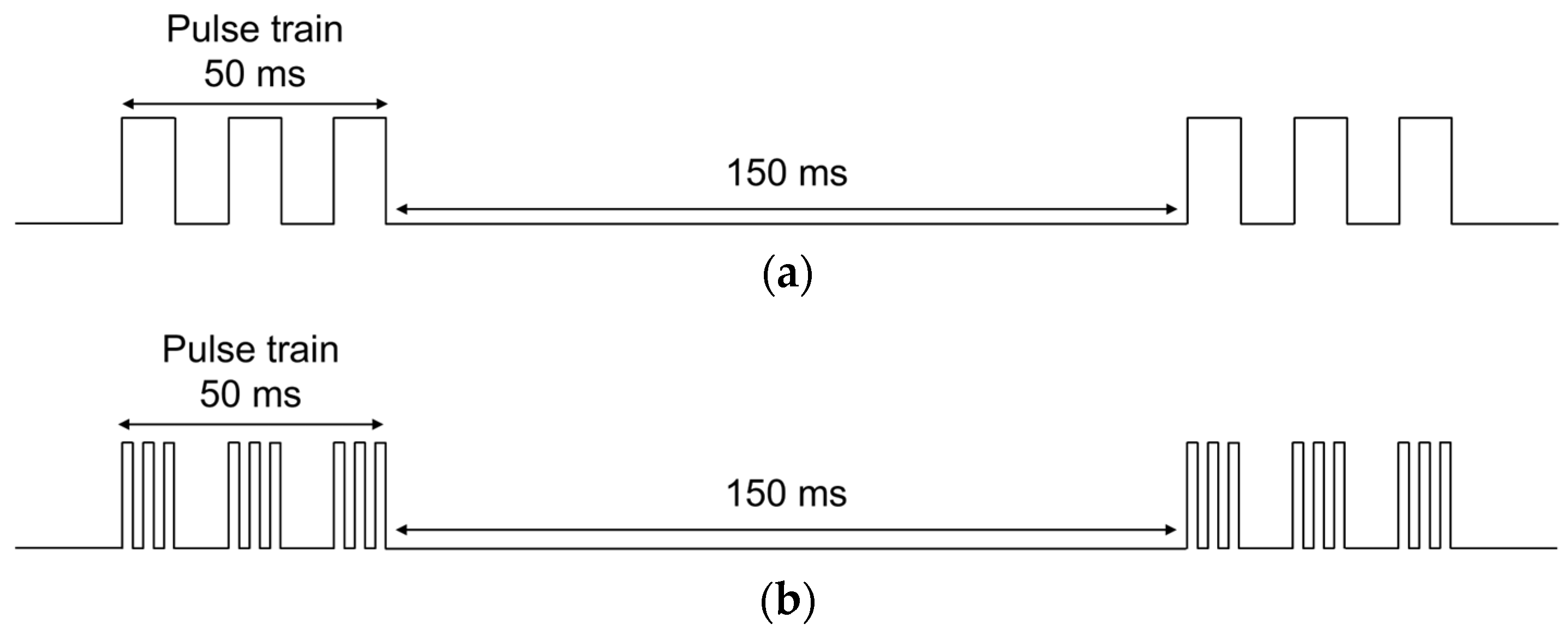
2.1. Theory of HF Magnetic Stimulation

HF pulse stimulation has the advantage of inducing higher electric fields with the same current compared to low-frequency pulses. Faraday’s Law is expressed as
× E i n d = B t ,
where E i n d is the induced electric field intensity and B is the magnetic flux density. This equation implies that even if | B | is small, a high rate of change over time can induce a strong electric field. For example, the magnetic field generated by a single loop ( p ) and current I ( t ) can be expressed as follows using the Biot–Savart law:
B r , t = μ 0 4 π I t p d r × r r r r 3 = × A ,
where μ 0 is the permeability of free space, r is the position vector of the coil, r is the position vector of the observation point, and A is the magnetic vector potential, respectively [20]. By substituting (2) into (1), E i n d can be calculated as
E i n d r , t = A t = μ 0 4 π d I t d t p d r r r .
This equation ultimately implies that the greater the rate of change in the coil current over time, the stronger the induced electric field.
In addition, the HF pulse train can improve the penetration depth of the electric field into biological tissue. The induced electric field from the time-varying magnetic field generates eddy currents that cause losses in the conductive medium. Conventional TMS systems generally use pulse frequencies below 100 Hz and can neglect the displacement current, which is proportional to the rate of time variation of the electric field. However, as the frequency increases, the rate of time variation of the induced electric field becomes sufficiently large to create a magnetic field, which in turn induces another electric field. This allows the electromagnetic field to penetrate deeper into human tissue.
This phenomenon can be corroborated by the electromagnetic simulation of a simplified model of human gray matter using COMSOL Multiphysics, as illustrated in Figure 3a. The simulations were conducted using the AC/DC module for frequencies up to 10 MHz with quasi-static approximation and the RF module for frequencies above 10 MHz with full-wave analysis, as recommended in the manual of the analysis tool. To generate a magnetic field, a single-loop coil with a diameter of 6 mm was placed 2 mm above the gray matter surface. Since the coil diameter does not have a significant effect on the trend of penetration depth according to frequency, a small size was selected considering the simulation time. Gray matter was implemented as a cube with a side of 150 mm, which is sufficiently larger than the coil, and was modeled with permittivity and conductivity that vary depending on frequency [21]. The maximum electric field E m a x at a specific depth ( d ) was approximately obtained below the circumference of the coil, simulated while varying the coil current frequency from 0.1 to 1200 MHz.
Figure 3b shows the E m a x normalized by B c o r e , E m a x / B c o r e , in the gray matter at various depths and frequencies where B c o r e represents the magnetic field at the center of the coil. As the frequency increases, the strength of the electric field also increases, which can be explained by (1)–(3). As the depth increases, the magnetic field decreases, and consequently, the induced electric field also decreases. Simultaneously, the impact of the conductive loss due to the eddy current becomes more significant, particularly at higher frequencies. In this figure, at a depth of 100 mm, this loss causes the electric field strength to decrease beyond 1.1 GHz.
Figure 3c shows the electric field penetration depth, defined as the depth where E m a x is 1/4 of the surface electric field intensity, as a function of frequency. This figure shows that as the frequency increases above 100 MHz, the penetration depth gradually increases, which can be attributed to the displacement current. However, excessively high frequencies can attenuate the electric field due to conductive losses resulting from eddy currents.
To exploit the advantages of HF pulse stimulation, the stimulation pulses can be replaced with HF pulse train. In this study, two HF magnetic pulse generators, operating at frequencies of 100 kHz and 1 MHz, are designed and evaluated.

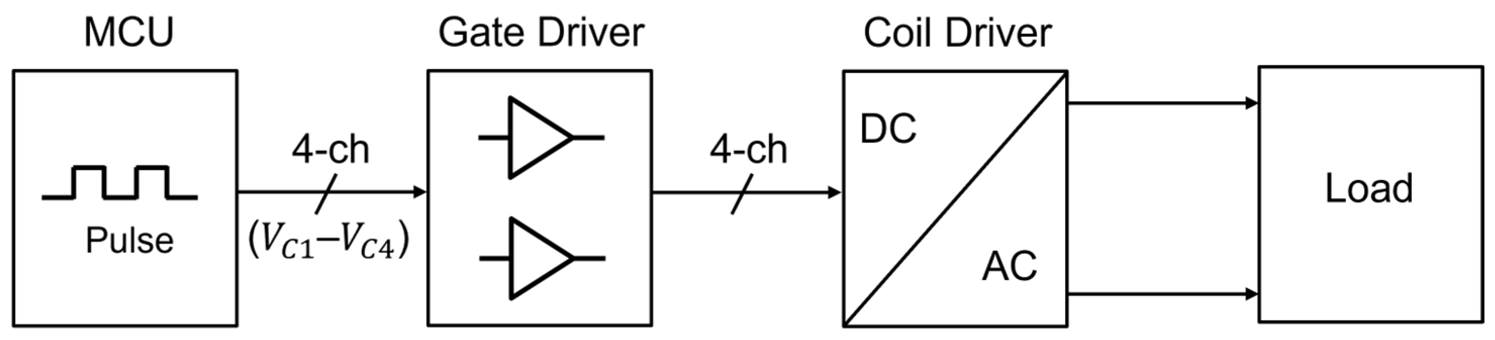
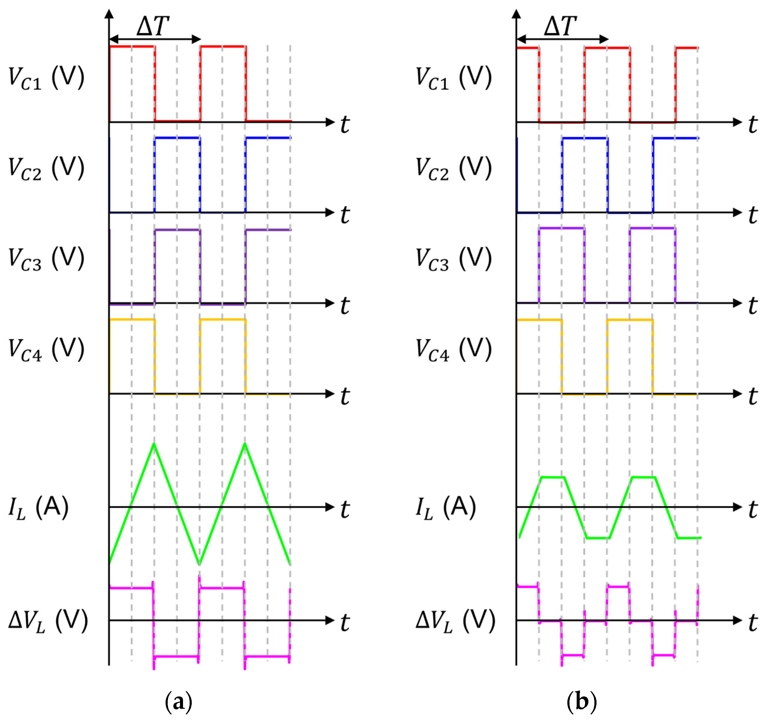
2.2. Design of HF Magnetic Pulse Generator

The proposed HF magnetic field generator is illustrated in the block diagram in Figure 4. The microcontroller unit (MCU) generates the on/off control voltages ( V C 1 V C 4 ). The gate driver is responsible for appropriately controlling the coil driver. The coil driver, supplying current to the load or coil, is implemented as a full-bridge circuit.
A schematic of the proposed gate driver and full-bridge circuit is shown in Figure 5. The gate driver supplies sufficient current to the gates of the MOSFETs in the full-bridge circuit, enabling rapid on/off switching. In a typical full-bridge circuit, pMOSFETs are used for the upper switch ( S 1 and S 2 ); however, in this study, high-speed nMOSFETs are employed for HF operation. To turn these upper nMOSFETs on and off, a bootstrap diode ( D b o o t ) and capacitor ( C b o o t ) circuit are designed, as illustrated in Figure 5.
The full-bridge circuit converts a DC voltage ( V D D , F ) to an AC voltage (pulses) and comprises four transistors ( S 1 S 4 ), each operating as a switch. Typically, a full-bridge circuit in TMS systems consists of insulated gate bipolar transistors to supply high current. However, in this study, nMOSFETs with excellent switching characteristics were used to enable operation at 1 MHz.
Figure 6 illustrates that the waveforms of the coil current ( I L ) in the coil ( L c o i l ) load shown in Figure 5 can be adjusted based on switching conditions of the transistors ( S 1 S 4 ) which are determined by the control voltages ( V C 1 V C 4 ). For example, a triangular waveform is synthesized in Figure 6a. During the first Δ T / 2 , where Δ T is the pulse period, S 1 and S 4 are turned on while S 2 and S 3 are turned off, causing the voltage across the coil to be V D D , F and the coil current to increase linearly. Then, the on/off states of each set of switches are reversed for the next Δ T / 2 , and the coil voltage is also reversed to V D D , F , causing the current to decrease linearly. This process results in a triangular waveform of the coil current with a peak value of V D D , F / L c o i l × Δ T / 2 . Therefore, the peak current can be controlled by adjusting V D D , F and Δ T .
The same circuit can produce a trapezoidal current waveform by adjusting the phase of S 1 S 4 , as illustrated in Figure 6b. When the coil current increases linearly in one direction, turning on both upper-side switches ( S 1 and S 2 ) (or both lower-side switches ( S 3 and S 4 )) while turning off all other switches results in no voltage difference across the coil, thus maintaining a constant coil current and leading to a trapezoidal waveform. The peak current can also be controlled in this configuration by adjusting the duty cycles of control signals.
At high frequencies, such as in the MHz range, parasitic inductance of the transistors and the transmission line ( L p in Figure 5) can cause ringing in the coil voltage. When two switches ( S 1 and S 4 or S 2 and S 3 ) are turned on, magnetic energy ( E p = L p I L 2 / 2 ) is stored in the L p . When the switching direction is reversed, the stored energy generates an LC-ringing waveform at the nodes A and B in Figure 5 [22]. Such ringing not only distorts the signal but also poses a risk of device damage due to excessive energy. To mitigate this problem, a bypass capacitor ( C b y p ) and damping resistor ( R d a m p ) are utilized, as illustrated in Figure 5. Bypass capacitors of 10 μF, 1 μF, and 0.1 μF in parallel were connected on the DC bias line to mitigate the effect of L p . R d a m p is connected in series with the gate of the MOSFET and, along with the MOSFET’s input capacitance ( C i n ), acts as an RC low-pass filter. This configuration suppresses the overshoot caused by rise time and L p . However, a large R d a m p can increase the rise and fall times, potentially degrading the switching performance.
HF switching of transistors leads to the increase in switching losses. In the gate driver, switching loss is significantly influenced by the gate charge ( Q g ) of the MOSFETs in the full-bridge circuit and the switching frequency ( f s w ). In the full-bridge circuit, the on-resistance ( R o n ) of the MOSFETS also contributes to channel loss. To reduce the overall power dissipation, MOSFETs with low Q g and R o n were employed. In addition, shoot-through current, which might directly flow from the power supply to ground during transition periods, can cause huge power dissipation and device failure. To avoid shoot-through current, dead time is incorporated in the control signals.

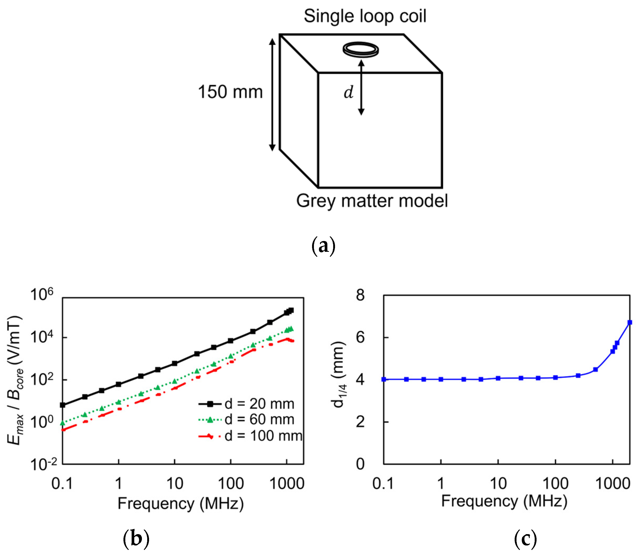
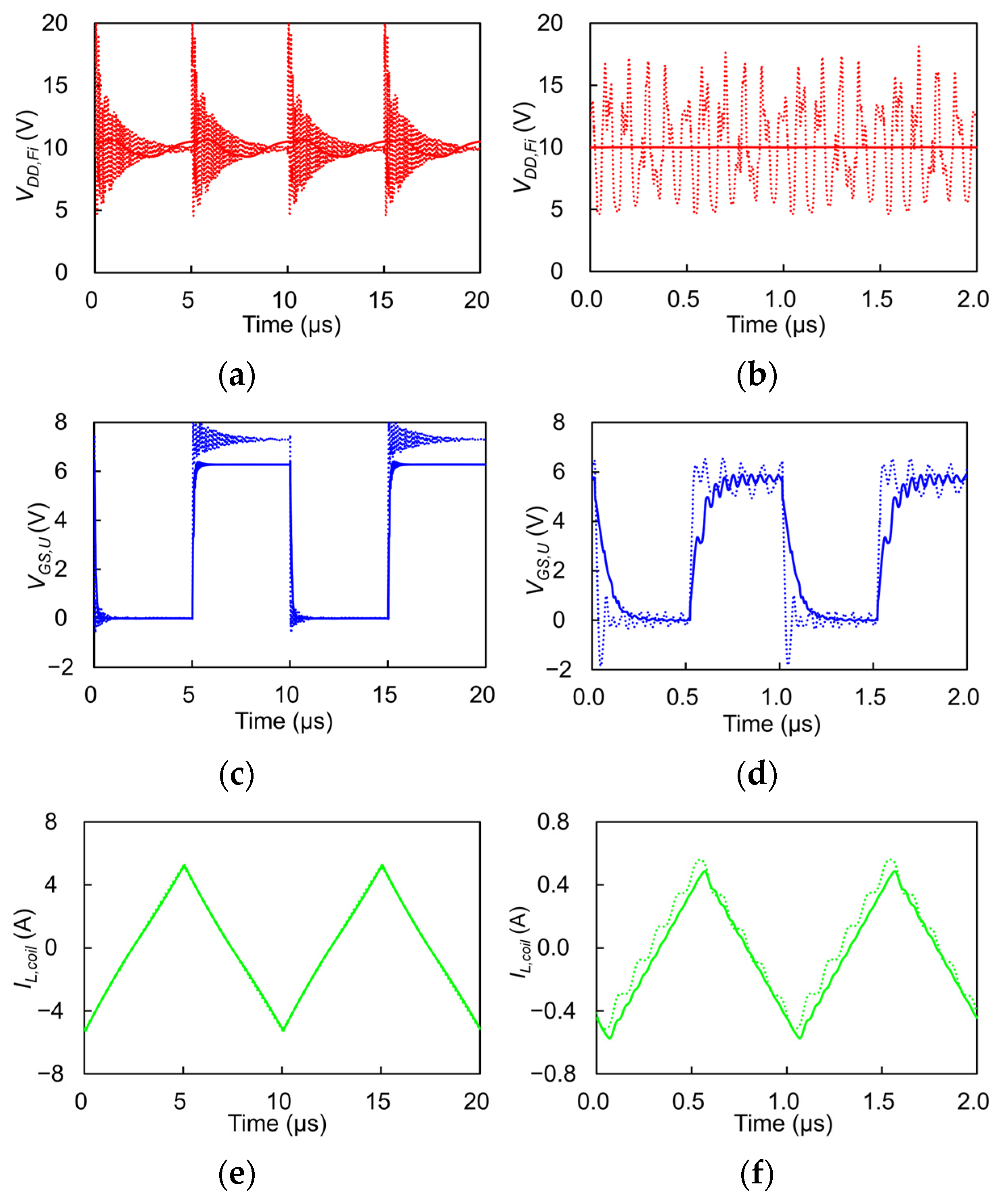
2.3. Simulation of HF Magnetic Pulse Generator

The gate driver, UCC27282 from Texas Instruments, was selected to rapidly charge and discharge the nMOSFETs in the full-bridge circuit. The full-bridge circuit is implemented using four nMOSFETs, CSD18511KCS from Texas Instruments. These transistors have the electrical characteristics of C i n = 4.6 nF, Q g = 31 nC, and R o n = 3.2 mΩ, making them suitable for low-power and high-speed operation. Considering the C i n , R d a m p is set to 6.8 Ω to obtain a cut-off frequency of 4.5 MHz, which suppresses overshoot without affecting the target frequency. The simulation was conducted using PSpice for TI from Texas Instruments.
For precise design, the parasitic inductances in the printed circuit board (PCB) traces were extracted using Keysight ADS electromagnetic simulation and incorporated into the overall simulation. Additionally, the inductance of the stimulation coil is set to 5 μH for high-speed operation, and its parasitic resistance and capacitance were included in the simulation.
Figure 7 shows the simulation results for the full-bridge circuit’s DC line voltage ( V D D , F i ), upper-side gate-source voltage ( V G S , U ), and current flowing through the coil ( I L , c o i l ) at operating frequencies of 100 kHz and 1 MHz, respectively, illustrating the impact of the presence or absence of the C b y p and R d a m p . V D D , F and V D D , G D were set to 10 V and 5.5 V, respectively. The theoretical maximum currents flowing through the coil are 10 App at 100 kHz and 1 App at 1 MHz. In Figure 7a,b, the addition of ringing suppression techniques visibly reduced the voltage ripple on the bias line. In Figure 7c,d, the presence of R d a m p reduces overshoot and ringing in V G S , U , but it also extends the rise time, leading to a slight reduction in the amplitude of V G S , U . In Figure 7e, although ringing is present in I L , c o i l , its absolute magnitude is very small compared to the current flowing through the coil, indicating that it does not pose a significant problem. However, as shown in Figure 7f, the current flowing through the coil at higher frequencies was relatively small, thereby magnifying the ringing impact. The use of C b y p and R d a m p effectively suppresses this ringing.

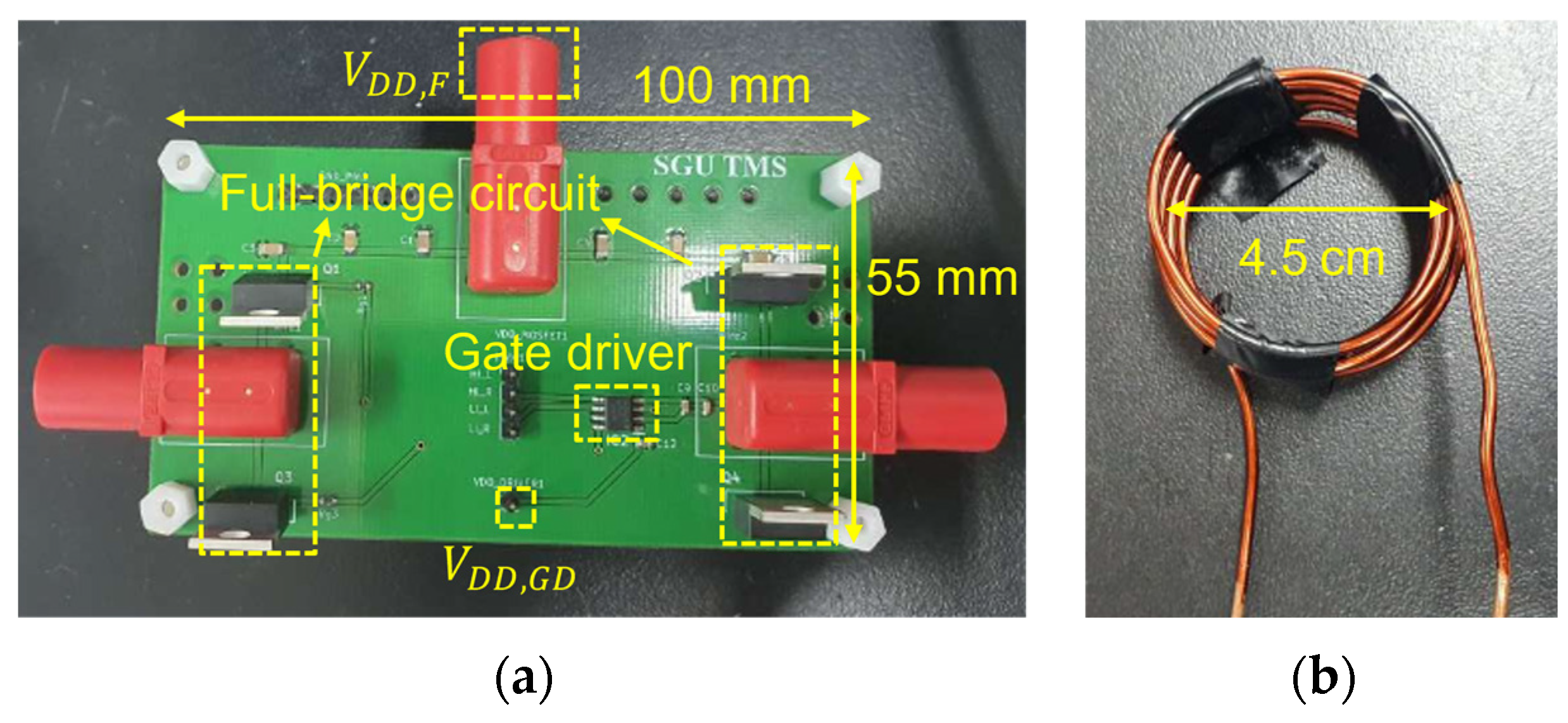
3. Fabrication and Experimental Results

Figure 8a shows the fabricated gate driver and full-bridge circuit on a single PCB measuring 100 mm × 55 mm. The coplanar waveguides with ground structure in a 35-μm thick copper layer were utilized to interconnect the devices and circuits on the FR4 substrate, which has a relative permittivity of 4.6 and a thickness of 2 mm. The circuit layout was designed to minimize parasitic inductance ( L p ) by shortening the interconnection lengths and to ensure symmetry between the left and right branches to minimize phase differences in the control signals. The fabricated coil, consisting of ten turns of AWG12 copper wire with a diameter of 4.5 cm, is shown in Figure 8b. It exhibits an inductance L c o i l of 4.7 μH and a resistance R c o i l of 75 mΩ, respectively.
For HF pulse generation, the Arduino Due MCU was selected due to its high system clock frequency of 84 MHz. Additionally, it features four or more independent timers, enabling precise phase control of the four control signals. The voltage and current waveforms in the circuit were measured using an oscilloscope (DSOX2014A from Keysight, Santa Rosa, CA, USA) with a voltage probe (TPP0201 from Tektronix, Beaverton, OR, USA) and a current probe (P6022 from Tektronix), respectively. The induced electric field by the stimulation coil was measured by using a search coil, as shown in Figure 9. The search coil is a single-turn circular coil with a radius ( R s ) of 2.25 cm, the same size as the stimulation coil. According to (4), the voltage ( V s ) measured from the search coil can be converted to calculate E i n d as follows [23]:
E i n d = V s 2 π R s .
The search coil was precisely positioned using an XYZ station (ST-JFGR-404060 from ST1, Incheon, Republic of Korea). A DC power supply (E3649A from Keysight) was used to apply the DC voltages and currents.
Figure 10 presents the measured time-domain waveforms of I L , c o i l and E i n d for a coil load at different frequencies: (a) and (c) correspond to 100 kHz, while (b) and (d) correspond to 1 MHz. The DC power supply voltages V D D , F = 10 V and V D D , G D = 5.5 V were applied to the banana connector and pin header, respectively, as shown in Figure 8a. The induced electric field was measured 1.5 mm away from the load coil. Figure 10a,b show that as the pulse frequency increases tenfold from 100 kHz to 1 MHz, the coil current decreases proportionally, approximately from 9.6 App to 1.1 App. This reduction was due to the increased impedance of the load coil by a factor of ten. However, as shown in Figure 10c,d, the measured induced electric field remained consistent with values of 6.5 and 6.8 Vpp/m, despite the reduction in coil current. This constancy arises because the induced electric field is proportional to the temporal rate of change in the coil current (i.e., d I L , c o i l / d t ). Thus, we demonstrate that the same electric field can be induced with a proportional decrease in current as the pulse frequency increases.
At 100 kHz, the power dissipation was 0.08 W for the gate driver and 2.24 W for the full-bridge circuit, totaling 2.32 W. At 1 MHz, the power dissipation was 0.74 W for the gate driver and 1.71 W for the full-bridge circuit, totaling 2.45 W. As the frequency increased, the current through the coil decreased, leading to reduced power dissipation in the full-bridge circuit ( P d i s s , F ). The reduction in coil current is advantageous as it decreases the losses in the coil, thereby reducing heat generation. However, the power dissipation in the gate driver ( P d i s s , G D ) increased due to higher switching losses. These values are summarized in Table 1. Overall, total power dissipation ( P d i s s , t o t a l ) was similar in both cases. The power dissipation can be reduced by employing the LC quasi-resonant load, as demonstrated in the following section.

4. Quasi-Resonant LC Load

The larger the current flowing through the coil, the stronger the magnetic field generated. As the pulse frequency increases, the impedance due to the coil inductance also increases, resulting in a decrease in current when the same voltage is applied. This phenomenon was confirmed in the experiments presented in Figure 10. In the same circuit, a larger current can be achieved at the same load voltage by reducing the load impedance. This can be achieved by connecting a capacitor ( C r e s ) in series with an inductor to exploit the resonance phenomenon. The resonant frequency ( ω 0 ) of the coil and capacitor and the load impedance ( Z l o a d ) can be expressed as
ω 0 = 1 / L c o i l C r e s ,
Z l o a d = R c o i l + j ω 0 L c o i l 1 / ω 0 C r e s .
At ω 0 , the load impedance equals R c o i l , which is typically small, enabling a large current to flow through the load.
A capacitance C r e s of 5.4 nF can resonate with a coil inductance L c o i l of 4.7 μH at f 0 = 1 MHz. However, this resonant configuration may result in a substantial voltage across the capacitor, posing a risk of component damage. In addition, excessive current can lead to significant coil heating. Therefore, a quasi-resonant load was designed in this study. Specifically, a 5.0 nF capacitor was utilized instead of a resonant 5.4 nF capacitor, resulting in a resonant frequency approximately 10% higher than the frequency of 1 MHz. Figure 11 shows the measured time-domain waveforms of I L , L C and E i n d , L C at the same distance as in the previous experiments, conducted with a quasi-resonant LC load at a frequency of 1 MHz. The coil current was measured to be 2.1 App, as shown in Figure 11a, exhibiting a quasi-sinusoidal waveform. It is noteworthy that only 1.8 V of the full-bridge circuit supply voltage V D D , F was required to generate this amount of the coil current due to the quasi-resonant configuration, while the supply voltage of the gate driver V D D , G D was maintained at 5.5 V. In Figure 11b, the measured electric field reached as high as 19.1 Vpp/m, which is about 2.8 times higher than the values obtained with the coil load at V D D , F = 10 V. Compared to the coil load, the quasi-resonant LC load exhibited a significant decrease in the power dissipation of the full-bridge circuit P d i s s , F , from 1.71 W to 0.44 W. This reduction contributed to lowering the total power dissipation to 1.11 W, approximately half of that with the coil load. Therefore, the quasi-resonant LC load offers the advantage of generating a larger current and consequently a stronger magnetic field and induced electric field, with reduced power dissipation, as compared in Table 1.

5. Conclusions

This paper presents the design and implementation of an HF magnetic pulse generator, specifically in the MHz range, for LI-TMS applications. Comparative experiments demonstrate that the HF pulse train can induce the same electric field with a smaller current compared to low frequency. Additionally, it is experimentally verified that the quasi-resonant LC load can generate a larger induced electric field while reducing power dissipation. This paper has implemented a system suitable for cost-effective LI-TMS, and we expect to validate its effectiveness in future in vivo experiments.

Author Contributions

Conceptualization, S.S. and J.J.; methodology, S.S. and H.K.; software, S.S. and H.K.; validation, S.S. and H.K.; formal analysis, S.S. and J.J.; investigation, S.S.; resources, J.J.; data curation, S.S.; writing—original draft preparation, S.S., H.K. and J.J.; writing—review and editing, S.S. and J.J.; visualization, S.S.; supervision, J.J.; project administration, J.J.; funding acquisition, J.J. All authors have read and agreed to the published version of the manuscript.

Funding

This research was supported by the Bio and Medical Technology Development Program of the National Research Foundation (NRF) funded by the Korean government (MSIT) (No. 2022M3E5E8081204).

Data Availability Statement

The original contributions presented in the study are included in the article, further inquiries can be directed to the corresponding author.

Conflicts of Interest

The authors declare no conflicts of interest.

References

  1. Barker, A.T.; Jalinous, R.; Freeston, I.L. Non-invasive magnetic stimulation of human motor cortex. Lancet 1985, 325, 1106–1107. [Google Scholar] [CrossRef] [PubMed]
  2. Hoogendam, J.M.; Ramakers, G.M.J.; Di Lazzaro, V. Physiology of repetitive transcranial magnetic stimulation of the human brain. Brain Stimul. 2010, 3, 95–118. [Google Scholar] [CrossRef] [PubMed]
  3. Huang, Y.Z.; Edwards, M.J.; Rounis, E.; Bhatia, K.P.; Rothwell, J.C. Theta burst stimulation of the human motor cortex. Neuron 2005, 45, 201–206. [Google Scholar] [CrossRef] [PubMed]
  4. Chung, S.W.; Hoy, K.E.; Fitzgerald, P.B. Theta-burst stimulation: A new form of TMS treatment for depression? Depress. Anxiety 2015, 32, 182–192. [Google Scholar] [CrossRef] [PubMed]
  5. Mi, T.-M.; Mei, S.-S.; Liang, P.-P.; Gao, L.-L.; Li, K.-C.; Wu, T. Repetitive transcranial magnetic stimulation improves Parkinson’s freezing of gait via normalizing brain connectivity. Npj Park. Dis. 2020, 6, 16. [Google Scholar] [CrossRef] [PubMed]
  6. Lanza, G.; Ferri, R.; Bella, R.; Pennisi, G.; Cantone, M. Repetitive transcranial magnetic stimulation in primary sleep disorders. Sleep Med. Rev. 2023, 67, 101735. [Google Scholar] [CrossRef]
  7. Bulteau, S.; Brunelin, J.; Duprat, R.; Bouaziz, N.; Szekely, D.; Giraud, P.; Renoult, L.; Le Bas, P.; Camus, V.; Januel, D. Intermittent theta burst stimulation (iTBS) versus 10 Hz high-frequency repetitive transcranial magnetic stimulation (rTMS) to alleviate treatment-resistant unipolar depression: A randomized controlled trial (THETA-DEP). Brain Stimul. 2022, 15, 870–880. [Google Scholar] [CrossRef] [PubMed]
  8. Hutton, T.M.; Downar, J.; Rajji, T.K.; Krepel, N.; Vila-Rodriguez, F.; Daskalakis, Z.J.; Blumberger, D.M. Dosing transcranial magnetic stimulation in major depressive disorder: Relations between number of treatment sessions and effectiveness in a large patient registry. Brain Stimul. 2023, 16, 1510–1521. [Google Scholar] [CrossRef] [PubMed]
  9. Paulus, W.; Peterchev, A.V.; Ridding, M. Transcranial electric and magnetic stimulation: Technique and paradigms. Handb. Clin. Neurol. 2013, 116, 329–342. [Google Scholar]
  10. Selvaraj, J.; Ganesan, S.; Yoganathan, S.; Palanisamy, P.; Vairamuthu, J. Transcranial magnetic stimulation: Design of a stimulator and a focused coil for the application of small animals. IEEE Trans. Magn. 2018, 54, 1–5. [Google Scholar] [CrossRef]
  11. Kagan, Z.B.; Chari, A.; Fried, P.J.; Pascual-Leone, A.; Kaye, H.L.; Islam, R. Reduced heat generation during magnetic stimulation of rat sciatic nerve using current waveform truncation. IEEE Trans. Neural Syst. Rehabil. Eng. 2019, 27, 937–946. [Google Scholar] [CrossRef] [PubMed]
  12. Sorkhabi, M.M.; Zamanian, A.; Soltani, M.; Vosoughi Vahdat, B.; Mosavi, M.R.; Jafari, S.; Shahi, F. Programmable transcranial magnetic stimulation: A modulation approach for the generation of controllable magnetic stimuli. IEEE Trans. Biomed. Eng. 2020, 68, 1847–1858. [Google Scholar] [CrossRef] [PubMed]
  13. Li, Z.; Guo, F.; Shi, H.; Hu, X.; Yu, S.; Yang, X. Modular pulse synthesizer for transcranial magnetic stimulation with fully adjustable pulse shape and sequence. J. Neural Eng. 2022, 19, 066015. [Google Scholar] [CrossRef] [PubMed]
  14. Fang, X.; Zhang, Y.; Li, J.; Wang, M.; He, L. An Efficient Pulse Circuit Design for Magnetic Stimulation with Diversified Waveforms and Adjustable Parameters. Sensors 2024, 24, 3839. [Google Scholar] [CrossRef] [PubMed]
  15. Capone, F.; Dileone, M.; Profice, P.; Pilato, F.; Musumeci, G.; Minicuci, G.; Ranieri, F.; Cioni, B.; Di Lazzaro, V. Does exposure to extremely low frequency magnetic fields produce functional changes in human brain? J. Neural Transm. 2009, 116, 257–265. [Google Scholar] [CrossRef] [PubMed]
  16. Rohan, M.L.; Parow, A.M.; Stoll, A.L.; Demopulos, C.M.; Friedman, S.; Dager, S.R.; Hennen, J.; Cohen, B.M.; Renshaw, P.F. Rapid mood-elevating effects of low field magnetic stimulation in depression. Biol. Psychiatry 2014, 76, 186–193. [Google Scholar] [CrossRef] [PubMed]
  17. Khokhar, F.A.; Budelmann, V.; Baron, E.; Navab, N.; Frangi, A.F.; Sotiras, A. Design and demonstration in vitro of a mouse-specific transcranial magnetic stimulation coil. IEEE Trans. Magn. 2021, 57, 1–11. [Google Scholar] [CrossRef]
  18. Sun, S.; Cho, Y.H.; Lee, S.Y.; Lee, C. Mouse Somatosensory Cortex Stimulation Using Pulse Modulated Transcranial Magnetic Stimulation. J. Korean Inst. Electromagn. Eng. Sci. 2016, 27, 482–485. [Google Scholar] [CrossRef]
  19. Hussain, I.; Park, S.M.; Shahzad, A.; Hong, S.M.; Looney, D.; Ahn, J. Quantifying physiological biomarkers of a microwave brain stimulation device. Sensors 2021, 21, 1896. [Google Scholar] [CrossRef]
  20. Zhang, N.; Sun, S.; Li, J.; Wang, M.; Lee, S.Y. Theoretical Analysis and Design of an Innovative Coil Structure for Transcranial Magnetic Stimulation. Appl. Sci. 2021, 11, 1960. [Google Scholar] [CrossRef]
  21. Gabriel, S.; Lau, R.W.; Gabriel, C. The dielectric properties of biological tissues: II. Measurement in the frequency range 10 Hz to 20 GHz. Phys. Med. Biol. 1996, 41, 2251–2269. [Google Scholar] [CrossRef] [PubMed]
  22. Taylor, R.; Manack, R. Controlling switch-node ringing in synchronous buck converters. Analog Appl. 2012. Available online: https://www.ti.com/lit/an/slyt464/slyt464.pdf (accessed on 16 July 2024).
  23. Asbeck, P.M.; Hang, A.; Mirbozorgi, S.A.; Wu, R.; Carrillo, R.E.; Shapiro, M.G.; Poon, A.S.Y. An Efficient Circuit for Pulsed Magnetic Neural Stimulation. IEEE J. Electromagn. RF Microw. Med. Biol. 2023, 7, 258–265. [Google Scholar] [CrossRef]
Figure 1. Basic principles of the TMS system.
Electronics 13 03160 g001
Figure 2. Stimulation protocols. (a) Traditional theta burst stimulation. (b) Proposed high-frequency stimulation.
Electronics 13 03160 g002
Figure 3. Simulation of the electric field intensity in human gray matter. (a) Simulation structure. (b) Normalized E m a x as a function of frequency. (c) Penetration depth of the electric field as a function of frequency.
Electronics 13 03160 g003
Figure 4. Block diagram of the proposed HF magnetic pulse generator.
Electronics 13 03160 g004
Figure 5. Schematic of the full-bridge circuit with boot-strapped gate driver.
Electronics 13 03160 g005
Figure 6. Simulated waveforms for the control signal ( V C 1 V C 4 ), the coil current ( I L ), and the voltage across the coil ( Δ V L ). (a) Triangular current wave. (b) Trapezoidal current wave.
Electronics 13 03160 g006
Figure 7. Simulated waveforms in the full-bridge circuit with (solid) and without (dot) bypass capacitor and damping resistor for V D D , F = 10 V and V D D , G D = 5.5 V. (a) V D D , F i , (c) V G S , U , and (e) I L , c o i l at 100 kHz. (b) V D D , F i , (d) V G S , U , and (f) I L , c o i l at 1 MHz.
Electronics 13 03160 g007
Figure 8. (a) Fabricated HF magnetic pulse generator. (b) Fabricated stimulation coil.
Electronics 13 03160 g008
Figure 9. Measurement setup for the induced electric field intensity.
Electronics 13 03160 g009
Figure 10. Measured waveforms for the inductor load with DC bias voltages, V D D , F = 10 V and V D D , G D = 5.5 V. (a) I L , c o i l and (c) E i n d at 100 kHz. (b) I L , c o i l and (d) E i n d at 1 MHz.
Electronics 13 03160 g010
Figure 11. Measured waveforms for the quasi-resonant LC load at the frequency of 1 MHz with DC bias voltages, V D D , F = 1.8 V and V D D , G D = 5.5 V. (a) I L , L C and (b) E i n d .
Electronics 13 03160 g011
Table 1. Summary of measurement results.
LoadFrequency
(MHz)
V D D , F
(V)
I L *
(App)
E i n d *
(Vpp/m)
P d i s s , F
(W)
P d i s s , G D
(W)
P d i s s , t o t a l
(W)
L0.1109.66.52.240.082.32
L1101.096.81.710.742.45
LC11.82.0919.10.440.671.11
* Peak-to peak value.
Disclaimer/Publisher’s Note: The statements, opinions and data contained in all publications are solely those of the individual author(s) and contributor(s) and not of MDPI and/or the editor(s). MDPI and/or the editor(s) disclaim responsibility for any injury to people or property resulting from any ideas, methods, instructions or products referred to in the content.

