Article

A Review of Multifunctional Antenna Designs for Internet of Things

by
Dimitrios G. Arnaoutoglou
,
Tzichat M. Empliouk
,
Theodoros N. F. Kaifas
,
Michael T. Chryssomallis
and
George Kyriacou
*
Department of Electrical and Computer Engineering, Democritus University of Thrace, 67100 Xanthi, Greece
*
Author to whom correspondence should be addressed.
Electronics 2024, 13(16), 3200; https://doi.org/10.3390/electronics13163200
Submission received: 5 July 2024 / Revised: 5 August 2024 / Accepted: 9 August 2024 / Published: 13 August 2024
(This article belongs to the Special Issue Antenna Designs for 5G/IoT and Space Applications, 2nd Edition)

Abstract

:
The Internet of Things (IoT) envisions the interconnection of all electronic devices, ushering in a new technological era. IoT and 5G technology are linked, complementing each other in a manner that significantly enhances their impact. As sensors become increasingly embedded in our daily lives, they transform everyday objects into “smart” devices. This synergy between IoT sensor networks and 5G creates a dynamic ecosystem where the infrastructure provided by 5G’s high-speed, low-latency communication enables IoT devices to function more efficiently and effectively, paving the way for innovative applications and services that enhance our awareness and interactions with the world. Moreover, application-oriented and multifunctional antennas need to be developed to meet these high demands. In this review, a comprehensive analysis of IoT antennas is conducted based on their application characteristics. It is important to note that, to the best of our knowledge, this is the first time that this categorization has been performed in the literature. Indeed, comparing IoT antennas across different applications without considering their specific operational contexts is not practical. This review focuses on four primary operational fields: smart homes, smart cities, and biomedical and implantable devices.

1. Introduction

Around the world, technology is advancing at a pace that surpasses anything previous generations could have imagined. Today, wireless communication has transformed from a privileged good to a necessary need in developed countries. To further increase the quality of life, a trend has emerged that exploits mobile communication protocols to interconnect more and more devices [1]. For this revolution to materialize, there is a need to establish a way to ensure that everything is connected to everything else. The Internet of Things (IoT) encapsulates this vision by integrating a diverse range of systems. Some popular examples include intelligent homes, industrial applications, advanced farming techniques, urban innovations, and the smart energy grid [2].
The IoT is an extensive network that connects a wide array of devices, enabling them to exchange data with one another at relatively high speeds [2]. For this vast network to function, these devices must incorporate some form of communication system, whether wired or wireless. Wired communication is generally preferred due to its high data transfer rates, low latency, reliability in packet delivery, and efficient power consumption. However, the necessity of physical connections makes it impractical for many applications, limiting its appeal. On the other hand, wireless communication offers flexibility and adaptability, allowing devices to be placed in various environments without the need for complex installation procedures. The goal is to make it available anywhere and at any time. Despite these advantages, wireless communication faces reliability issues. The quality of a wireless link between two devices can be influenced by several factors, including range, environmental conditions (such as humidity and proximity to the ground), interference, and more. These factors can lead to increased data loss, jamming, connection drops, high latency, and even loss of control over the devices [2]. Therefore, there is a pressing need to develop more reliable and efficient wireless communication methods while also minimizing the power consumption of the devices involved.
The wireless connection of two devices involves communication via electromagnetic (EM) waves that can be divided into two major categories: optical and microwave links. Optical systems utilize EM waves in the infrared or visible light spectrum, enabling high data transmission rates. However, optical communication is primarily limited to line-of-sight (LoS) applications because light cannot penetrate obstacles like walls and can be disrupted by weather and environmental conditions. In contrast, microwaves, while they are relatively immune to weather and environmental conditions, allow the penetration of signals through various objects, facilitating non-line-of-sight (non-LoS) communication. Within microwave systems, antennas play a crucial role in wireless communication. Antennas are capable of emitting or receiving EM waves from their radiating surface, efficiently converting them to or from electrical currents, thereby enabling the exchange of information over distances without the need for physical connections.
Designing antennas for IoT applications presents unique challenges due to the diverse requirements of each application field (such as vehicle-to-vehicle communications (V2V), biomedical implants, smart sensors, etc.). A versatile antenna designed for IoT purposes must tackle several objectives, including easy deployment, minimal physical size, and the capability to efficiently receive a wideband response. Often, these demands are met by designing antennas that are omnidirectional or quasi-isotropic and support multiple polarizations, often in the form of printed antennas [3], especially for smart home applications. Depending on the specific application, more specialized antenna types may be necessary. For instance, durable antennas are essential for use in harsh environmental conditions (e.g., agricultural fields), whereas biomedical applications may require antennas that are more flexible and efficient to be placed in a patient and immersed in the highly lossy human body [4]. In scenarios requiring high data throughput, antennas capable of wideband, dual-band, or even multi-band operation become critical. For 5G and future generations where space-division multiple access (SDMA) is utilized, antennas with reconfigurable radiation patterns that can produce non-overlapping multi-beams while operating within a specific communication protocol are prioritized [5]. Additionally, the EM link may need to exhibit different polarizations, such as linear and circular–elliptical (right- or left-hand rotating). This feature calls for multi-polarized IoT antennas to allow parallel simultaneous propagation of orthogonal signals, increasing the communication capacity. These situations underscore the need to develop novel antennas or re-engineer existing ones to enhance the designer’s toolkit. The goal is to accommodate a broader range of applications while also enabling precise adjustments to optimize critical performance indicators of the antenna.
In recent years, a growing number of innovative antenna designs have been introduced in the academic literature, targeting one or more of the above objectives to ensure their compatibility with IoT devices. Various methods are employed in the design and optimization of these antennas, including characteristic mode analysis [6,7], full-wave solvers [8], equivalent circuits [9], and analytical solutions [10]. Currently, the most common approach involves using numerical full-wave electromagnetic or multiphysics solvers. This process starts with a basic antenna structure, such as a rectangular patch antenna, which is then modified through the addition of slots, new elements, or even a complete redesign [11]. Subsequently, parametric or optimization methods are applied to fine-tune the antenna’s performance to meet specific operational criteria. Once the design is finalized, a prototype is manufactured and tested under small-signal conditions to evaluate its S-parameters, radiation pattern, and efficiency [8].
The effectiveness of an antenna is typically assessed based on its size, bandwidth, axial ratio (for circularly polarized antennas), reconfigurability, and manufacturability. Recent reviews on IoT antennas classify them based on attributes such as reconfigurable properties [12], design methodology [8], type [13], bandwidth [14], and the kinds of tunable elements utilized [15]. Occasionally, review papers introduce new metrics to facilitate a more equitable comparison among different antenna designs. One such metric, the axial-to-impedance bandwidth ratio, was proposed to evaluate an antenna’s capability to function as circularly polarized (CP) throughout its entire operational bandwidth [15]. This metric and similar others aim to quantify the performance and suitability of antennas for specific applications.
The term “IoT” includes a wide range of applications, each with its unique requirements, making it overly simplistic to presuppose that any IoT antenna is suitable for all IoT applications. When an antenna is identified as suitable for IoT, it is essential to specify its operational domain. For instance, a wideband, high-gain, and beamforming-capable antenna might be ideal for IoT applications in 5G networks but less suitable for others [4]. Therefore, comparing IoT antennas across different applications without considering their specific operational contexts is impractical.
To address this issue, we undertake a comprehensive review of IoT antennas, categorizing them based on their field of operation within IoT. This approach requires selecting the most representative categories of IoT applications, considering the unique nature of each application and the specific antenna characteristics it demands. This review focuses on four primary operational fields: biomedical and implantable devices, smart homes, and smart cities. It is important to note that even within these categories, there are sub-categories with vastly different requirements (for example, the differences between implantable and wearable antenna specifications). This review represents the first attempt, to the authors’ knowledge, to compare IoT antennas based on characteristics tailored to specific applications, providing a clear understanding of how antenna designs can meet the diverse needs of the IoT landscape.

2. Materials and Methods

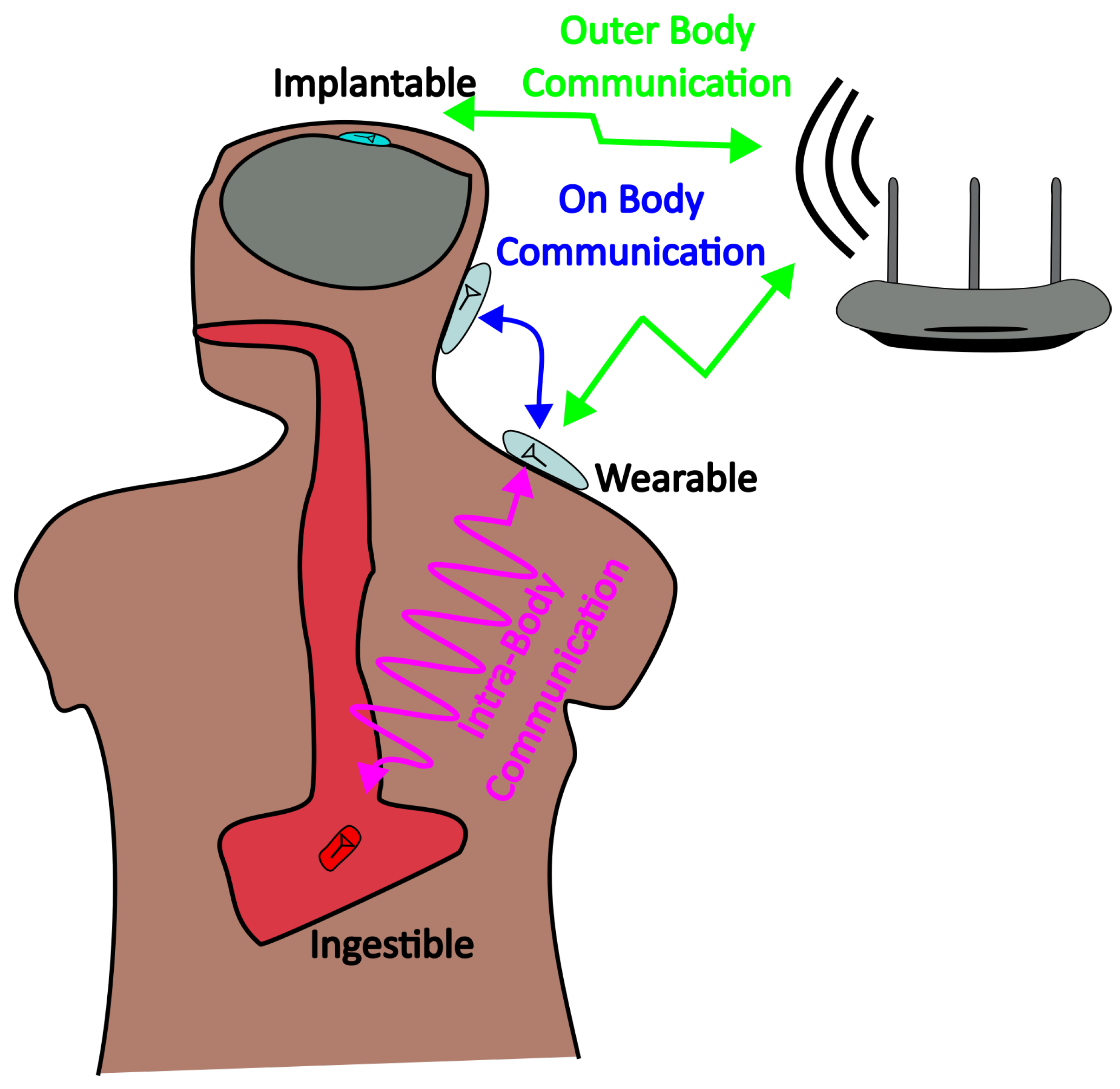
2.1. Biomedical Devices

The Medical Internet of Things (Medical IoT) represents a groundbreaking integration of medical devices with individuals, utilizing wireless communication to enable the exchange of healthcare data, facilitate remote patient monitoring, and significantly improve the quality of life for patients [4]. This innovation not only promises to enrich lives but also aims to enhance the quality of care and introduce cost efficiencies within healthcare institutions. The implementation of the Medical IoT in the healthcare sector is rapidly expanding on a global scale, though it encounters a variety of obstacles that need to be addressed to widen its application. These challenges include, but are not limited to, scalability, mobility, cost, complexity, management, trust, security, and interoperability.
Medical IoT applications can range from simple biological metrics, such as blood pressure [6] or temperature [16], to more complex measurements like the concentrations of certain substances [17]. The devices responsible for this monitoring need to be sufficiently small to be implantable [6], ingestible in the form of a capsule [18], or wearable [16]. Beyond the real-time wireless monitoring of various physiological parameters, a variety of emerging applications have been highlighted in recent studies. These include:
  • The management/treatment of brain disorders [19] through brain–computer interfaces (BCIs) that enable direct communication between the brain and an external device [20,21];
  • The Tongue Drive System (TDS), which allows for control of devices through tongue movements [22];
  • Leadless pacemakers that provide cardiac rhythm management without the need for wired leads [23];
  • Neurostimulators that deliver electrical stimulation to targeted areas of the brain or nervous system [24];
  • Techniques for imaging blood vessels to support diagnosis and treatment planning [25];
  • Drug delivery systems designed to release medications in a controlled manner at targeted locations within the body [26].
These advancements illustrate the broad and evolving scope of the Medical IoT in enhancing healthcare delivery and patient care.

2.1.1. Challenges of Ingestible and Implantable Antennas

In recent years, there has been a rapid development of wearable sensors and transmitters, making them an easily accessible and commercially available option where simple patch antennas are sufficient [4]. Different examples of biomedical antennas are presented in Figure 1. However, IoT antennas for implantable and ingestible devices present a significant challenge for the designer. The human body is conductive and presents high dielectric constants [27], primarily due to its water content and the electrodes. This electromagnetically hostile environment complicates the development of miniature and efficient antennas capable of penetrating human tissue to transmit data to an external receiver when the sensor is located inside the patient’s body. For these applications, the antenna must achieve high efficiency, operate at low frequencies, and have a small footprint.
High efficiency is crucial for these devices as their power supply is limited; they either use small batteries, which cannot be frequently replaced, or rely on energy harvesting or wireless power transfer techniques [4]. Additionally, to ensure that the signal can be transmitted outside of the human body, operating at a longer wavelength is beneficial, as it facilitates easier signal transmission through heterogeneous human tissues. Moreover, given the requirement for these devices to be implanted or ingested, it is imperative that the antennas have a low profile to fit within the confined spaces of a small capsule [18] or implantable device [28]. Based on the application, the size and the shape of the implantable antenna may differ, but in most cases, a few dozen mm3 of volume is needed for their placement inside the human body. On the other hand, the data rate is not deemed a critical factor for these types of devices, as the data collection from measurements is expected to occur at relatively low sampling frequencies (less than 1 Hz), focusing instead on the reliable transmission of crucial health metrics. As a result, electrically small antennas have become increasingly attractive for such applications [4].
Designing electrically small antennas presents significant challenges, primarily due to their extremely low efficiency, often a result of the platform effect seen in printed structures, and the complexity of their operation in the near field, which complicates the analysis [4]. Furthermore, due to their low operating frequencies, their bandwidth is limited to low-data-rate applications. The preferred operating frequency for most implantable antennas falls within the free bands allocated for industrial, scientific, and medical (ISM) applications (433, 915, and 2450 MHz). Among the various designs, printed planar loop antennas are the most commonly utilized for these applications [19,29]. These antennas are favored for their compact size and high efficiency, attributed to their primary excitation of magnetic fields, which are more capable of penetrating the highly dielectric and lossy human tissue compared to electric fields. This makes printed loop antennas particularly well suited for implantable devices, where efficient communication through human tissue is essential. On the other hand, in a conformal configuration, the antenna is wrapped inside the device package to minimize the occupied space while maintaining a large electrical size [30]. This structure is observed in capsule-like ingestible antennas (endoscopy). Their cylindrical shape is optimal, providing a smooth curvature for antenna wrapping [31]. However, in recent years, different types of magnetoelectric antennas have been proposed to achieve low operating frequencies while maintaining a low footprint (<10 mm3) in order to fit inside leadless pacemakers and brain devices [32,33].

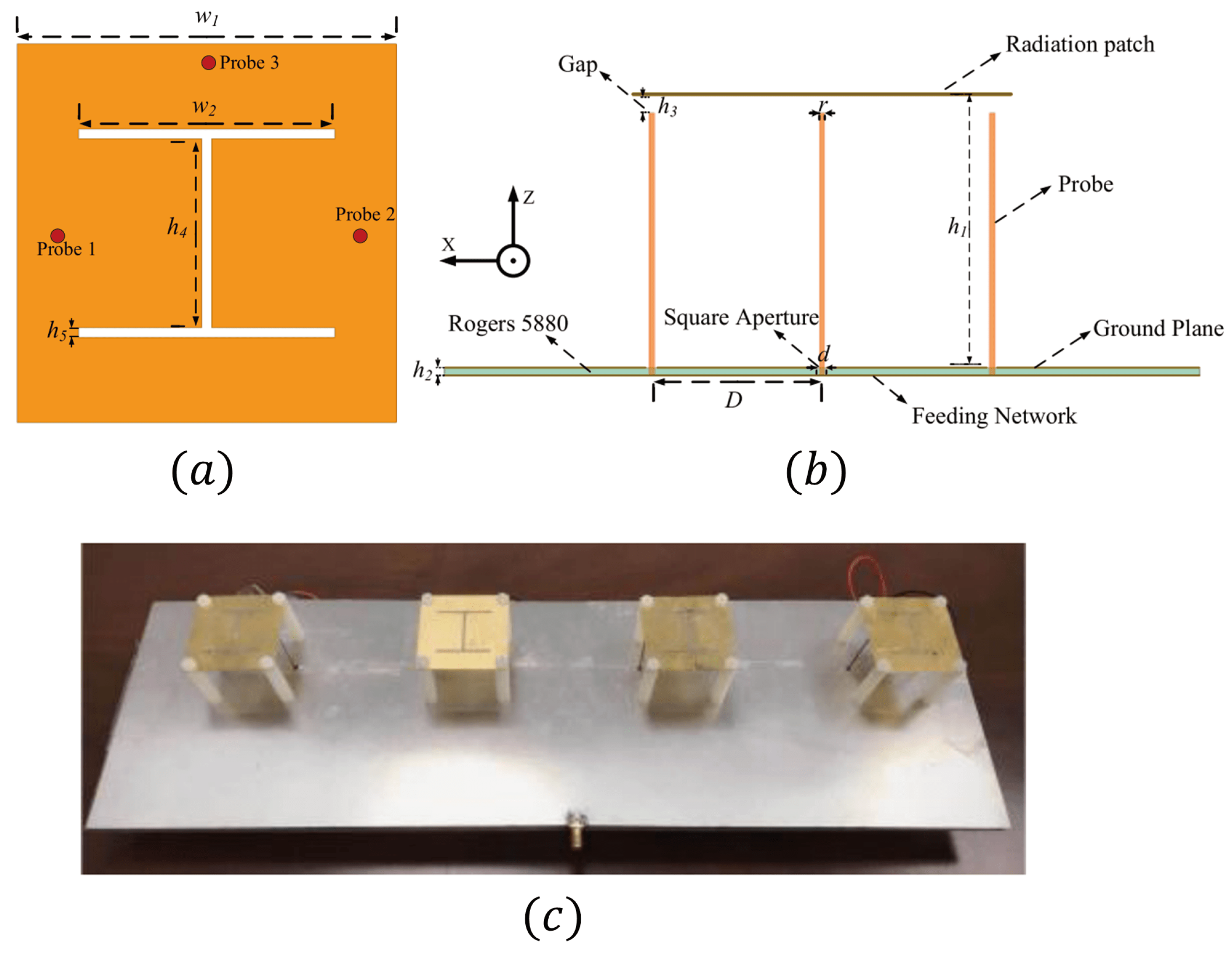
2.1.2. Planar Loop Antennas

A novel rectangular loop implantable antenna design featuring three concentric loops was introduced, utilizing an I-shaped ground to significantly enhance tuning across operational bands [34]. Polydimethylsiloxane (PDMS) was chosen as the material for both the substrate and superstrate due to its favorable properties for implantable medical devices. The performance and safety of the overall antenna structure were evaluated using realistic human scalp phantom models and a homogeneous skin box to closely mimic the conditions of implantation. The simulation studies of this antenna design indicated that it operates effectively around 5.8 GHz. Concerning safety, the specific absorption rate (SAR), which measures the rate at which energy is absorbed by the human body when exposed to an RF field, was found to be 0.28 W/kg for the skin box and 0.26 W/kg for human scalp phantoms. The safety levels based on Institute of Electrical and Electronics Engineers (IEEE) and Federal Communications Commission (FCC) standards [35] are 1.6 W/kg and 2 W/kg when 1 g and 10 g of head tissue is exposed to EM radiation. It is important to note that these limits are valid for the RF frequency range of 100 kHz–300 GHz. This demonstrates the antenna’s suitability for safe use within the specified operational parameters (1 mW input power). The transmitting system is powered by a battery source, which limits the operational period, particularly for cranial implants. Additionally, while selecting a high operating frequency can reduce the size of the system compared to other designs, it also results in a decreased gain of −32 dB. This reduction in gain confines the system’s application primarily to shallow implants, where such low gain is less critical.
To further simplify the RF transceiver circuitry and eliminate the need for Baluns (balance to unbalance converters) required by single-ended antennas, differential loop antennas have been introduced as a solution [18,36]. These antennas feature an inductively coupled feed structure alongside dual-band meandered radiators, achieving a −10 dB impedance fractional bandwidth of 10.2% with the circular-shaped foldable circuitry frequently used in commercial ingestible capsules. Utilizing a realistic phantom for testing at 2.45 GHz, the antenna demonstrated a gain of −27.9 dB, indicating potential suitability for applications in wireless ingestible capsule technology. However, the frequency of operation was adjusted due to the structural complexity, which may be attributed to the flexibility of the foam. This raises concerns about the behavior of the system when inserted inside the human body. Furthermore, such antennas present high reactive impedance due to the inductive coupling, making the matching between the antenna and chip a complex procedure.

2.1.3. Meander Antennas

Meandered patch radiators are an innovative approach to minimizing antenna size, particularly effective in scenarios requiring biocompatible materials. Such antennas are normally placed inside a plastic capsule in the shape of a pill in order to be swallowable (Figure 2). In one specific design [21], alumina serves as the dielectric substrate. This antenna incorporates a defected ground structure and a shorting pin to optimize its performance. It is strategically positioned between the cortical bone and dura layer within a seven-layer human brain phantom to assess its effectiveness in facilitating the transmission of neural signals to external devices or computers, a key function in the brain–computer Interface (BCI). The SAR was determined to be an enormous value of 682 W/kg when averaged for a 1 g tissue sample and 77.1 W/kg averaged over a 10 g tissue sample for 1 W power input. These findings demand that to avoid harmful effects on human brain tissue the antenna can safely operate at input power levels of 25 μ W and 3.24 μ W, respectively, much smaller than the expected power around 1 mW. The SAR limit is the same as defined earlier.
A dual-band meandered patch antenna design is demonstrated in [37]. This miniaturized antenna, with dimensions of 5 × 5 × 0.635 mm3, displayed a wideband response, namely, 300 MHz in the 1.4 GHz band and 380 MHz in the 2.45 GHz band. Its meander-shaped microstrip patch configuration not only provides a low-profile form factor but also simplifies integration with other circuits. The meandered slots play a critical role in tuning the antenna, enhancing its bandwidth, and minimizing its size. To achieve further size reduction, a material with a high relative permittivity ( ϵ r = 10.2 ) was chosen for the antenna’s substrate (Rogers RT/Duroid 6010). Additionally, the introduction of ground slots adds a parasitic element that boosts the antenna’s radiation efficiency to a total of 1%. The proposed antenna’s functionality in wireless bio-telemetry applications is demonstrated through the use of a pair of wireless transceivers. This setup highlights the antenna’s capability for sustainable and stable wireless data transmission, achieving a high data rate of 2 Mb/s over a distance of up to 20 cm when the receiver is placed on the body surface.

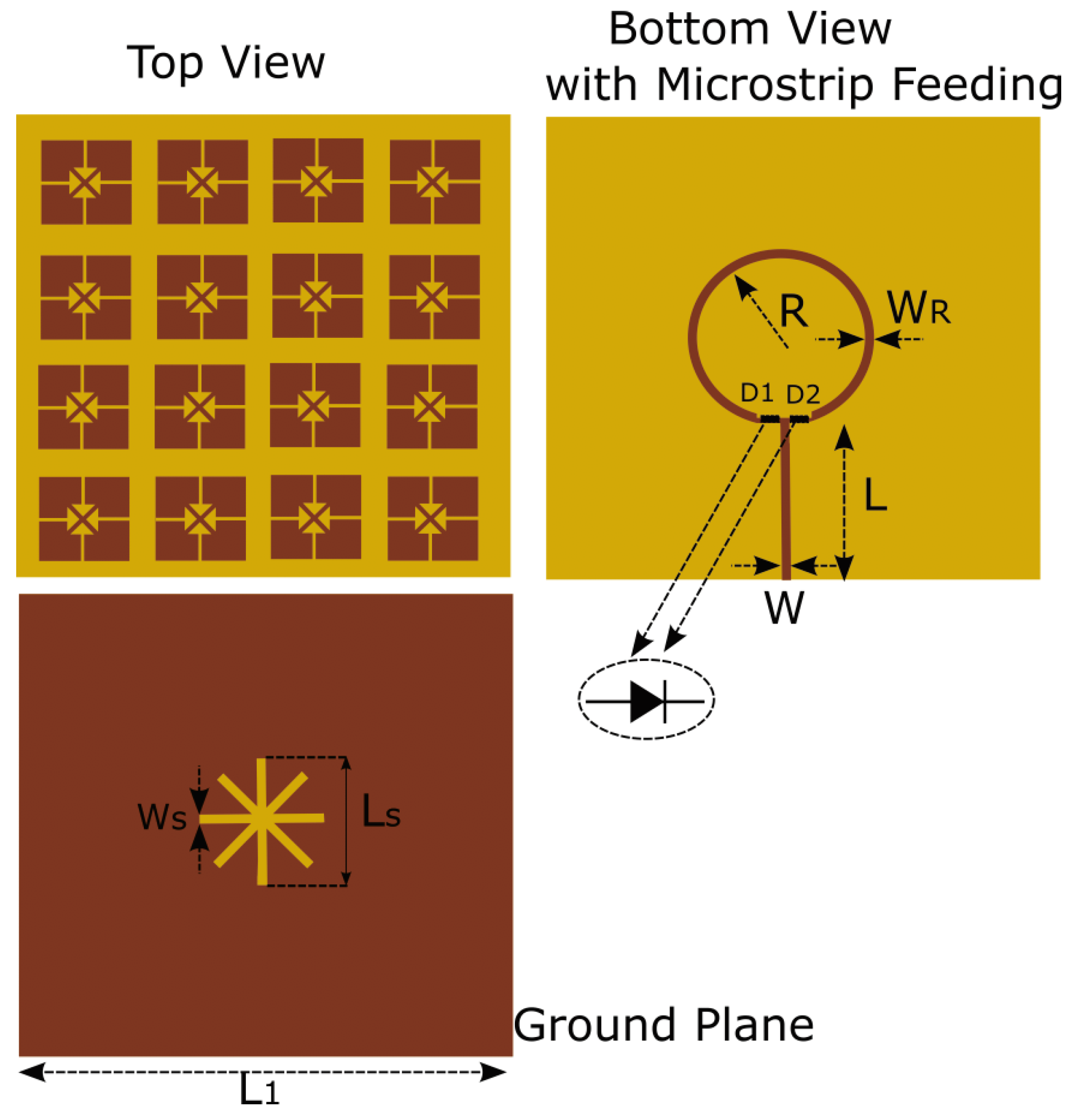
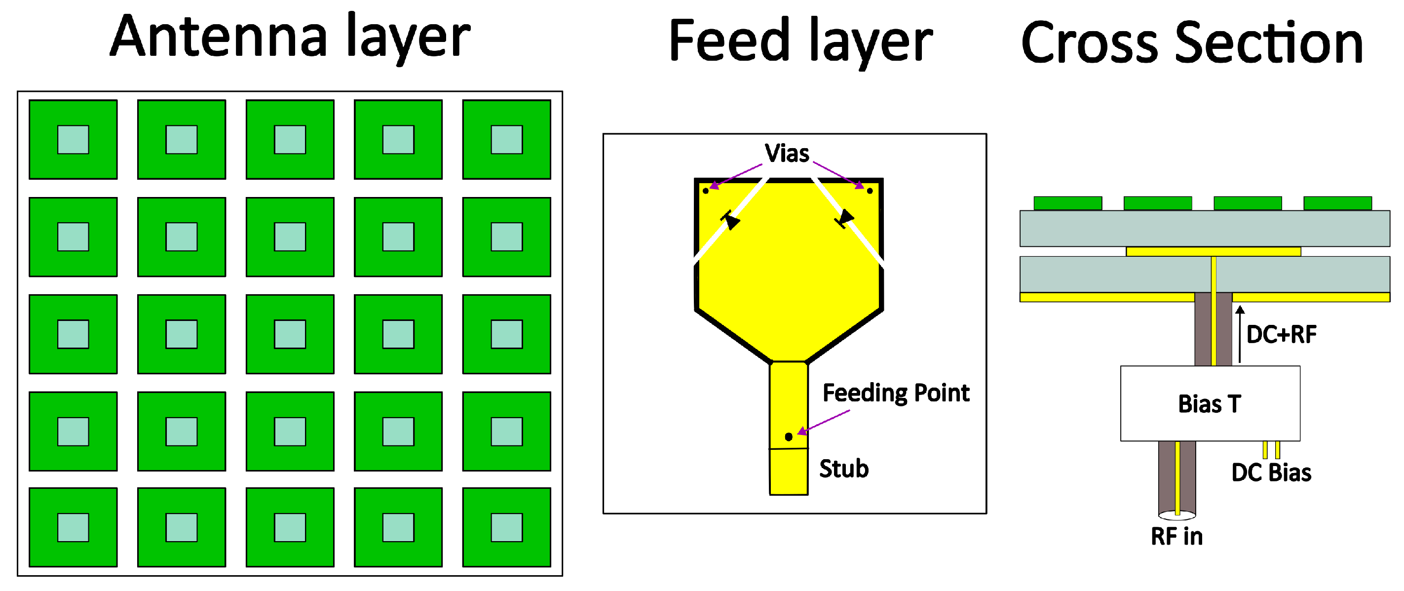
2.1.4. Various Antenna Types

In the realm of antenna design, especially for applications requiring operation within or around the human body, a variety of innovative electrical structures have been explored and documented in the literature. Some indicative examples include planar inverted-F antennas (PIFAs) [38,39], dielectric resonator antennas (DRAs) [40], metamaterial-based antennas [41], and Vivaldi antennas [42]. Each of these designs offers unique advantages for specific applications, addressing different challenges related to size, efficiency, and bandwidth.
In particular, the Vivaldi antenna [42], when embedded vertically against the dura mater within a skull phantom, demonstrates particularly noteworthy performance characteristics. This configuration results in increased radiation gain directed toward the end-fire orientation of about 30 % with respect to the conventional antenna, namely, with an average gain of 15.7 dBi across a wide bandwidth range from 3 to 5 GHz. This extensive bandwidth may go underutilized because even the most bandwidth-intensive modulation schemes used in such applications will not exceed 100 MHz. However, this antenna can offer versatility in its frequency of operation, particularly if certain frequencies experience high attenuation. Furthermore, a link budget analysis of this skull-embedded Vivaldi antenna underscores its potential for reliable wireless communication within the challenging harsh environment of the human body. The analysis indicates that effective communication can be maintained over a distance of 10.8 cm between the two antennas (receiver and transmitter), even with a transmitted power as low as 25 dBm [42]. Another advantage of the antenna is the low SAR, which permits higher power input in comparison with previously mentioned antennas (5 mW).

2.1.5. Magnetoelectric Antennas

A novel class of antennas, particularly suitable for low-frequency (LF) applications where compact size and device integration are critical has been gaining attention. For example, the absorption of LF magnetic fields in human tissue is notably lower, enhancing the suitability of antennas generating dominant magnetic fields for use in or near the human body. These antennas exploit magnetoelectric (ME) coupling and electromechanical resonance (EMR) to address the limitations traditionally associated with conventional electric field antennas, particularly in terms of efficiency and miniaturization, for very high frequency (VHF) and ultrahigh-frequency (UHF) applications. Unlike conventional EM antennas that resonate based on electromagnetic properties, LF ME antennas operate by resonating at the mechanical frequency of their physical structure, which allows for a significant reduction in their overall size.
In ME or multiferroic or mechanical antennas, a low-frequency AC magnetic field ( H A C ) interacts with a magnetostrictive layer, causing a periodic rotation of magnetic domains and a shift in domain boundaries [43]. This interaction generates a mechanical strain, which, when transferred to an acoustically coupled piezoelectric layer, results in electrical polarization (or the reverse process, depending on the operation mode). Acoustically driven antennas can operate at resonant wavelengths that are up to 10 5 times smaller than their electrical counterparts, providing a substantial advantage in terms of miniaturization and efficiency for specific applications. It is important to note that the term high efficiency is denoted for ME when compared with the same dimensions of electric current-based antennas at the same frequency. This means that the efficiency may not be high as compared to conventional antennas, but their size is smaller while keeping the efficiency at acceptable levels.
One of the standout features of acoustic antennas is their real resonant impedance, while electrically small antennas of similar size present high reactance [43]. Notably, high real input impedance means that the antenna can accept and then radiate a significant amount of power. On the contrary, high input reactance causes the reflection of the power fed to the antenna. This unique operation mechanism allows LF ME antennas to achieve remarkable miniaturization and higher efficiency compared to embedded traditional EM antennas. Moreover, ME antennas can possess the dual functionality of wireless energy harvesting and sensing at different frequencies, expanding their utility beyond data transfer [44]. This dual capability, combined with their compact size and acceptable efficiency ( 0.5 % ), positions ME antennas as a promising solution for advancing the functionality and performance of a wide range of low-frequency applications, including those in the medical field.
Despite the above benefits, it is important to note that the radiation efficiency of acoustic antennas can vary widely depending on how the acoustically driven antenna is implemented [45]. While the impedance characteristics are a common trait among most acoustic antennas, leading to enhanced matching efficiency, the specific design and fabrication of an acoustically driven antenna play a crucial role in determining its overall radiation efficiency.
A groundbreaking development in ME antenna technology involves a self-biased, miniaturized LF ME antenna, as proposed in [46]. This antenna operates at an electromechanical resonant frequency of 49.9 kHz, and its volume has been significantly reduced to only 1.75 mm3, making it substantially smaller than comparable EM antennas. The design features a piezoelectric layer sandwiched between two magnetostrictive layers, effectively leveraging the magnetoelectric effect for signal generation and reception. The performance of this antenna was evaluated both in air and within a specially optimized three-layered (skin, fat, and muscle) human tissue-mimicking phantom as a function of the frequency, to explore its potential for deep-body communication applications. In tests, the maximum received power was recorded at 20 nW in air and 8 nW in the phantom media at a distance of 1.2 m from the source. Notably, this ME antenna exhibits a significantly lower path loss of only 0.57 dB/m, compared to antennas operating at higher frequencies. In such cases, due to low operating frequency, the data rate is limited as in the case of [47], where for a center frequency of 274 kHz a rate of 220 kbps was achieved. However, in the tests, vibrations due to the body were not taken into consideration, which eventually will degrade the efficiency of the antenna.
In a similar approach to advance implantable medical devices, an ME antenna described in [44] has been integrated within a CMOS energy harvester chip. This combination aims to establish a wireless communication link specifically designed for fully integrated implantable devices, targeting the dual objectives of energy harvesting and signal transmission. The system is designed to perform two critical functions: first, to receive pulse-modulated power from a nearby transmitter, enhancing the device’s operational longevity without the need for physical connections; and second, to accurately sense and transmit low-magnitude neural signals, facilitating advanced medical monitoring and therapeutic interventions. A piezoelectric layer made of aluminum nitride (AlN) was connected via epoxy with a magnetostrictive layer composed of iron gallium boron (FeGaB). The antenna operates at two different frequencies, corresponding to its width and thickness resonances, which are optimized for the specific requirements of neural implant applications.
To evaluate the efficacy of ME antennas, a wireless test platform was developed in [44], serving as a valuable tool for neural implant design and testing, as seen in Figure 3. This setup includes an RF measuring system to test the ME antenna behavior, while coils are used to produce AC and DC magnetic fields. In more detail, the DC magnetic field is needed to bias the magnetostrictive material, and the AC low-frequency magnetic field is sensed through the antenna. An RF signal is transmitted through software defined radio (SDR), which is collected from the antenna acting as a harvesting device, and measured using a spectrum analyzer. Finally, the SDR can receive an RF signal from the ME, which carries the information about the intensity of the low-frequency magnetic field. Utilizing this platform, the integrated system demonstrated its capability by successfully transmitting a magnetically modulated action potential waveform. Neuronal activity generates small transient currents that produce small neural magnetic fields (NMFs) [48]. The ME antenna is capable of detecting these NMF signals due to its low operating frequency. The test configuration was developed to simulate the magnetic field generated by brain activity using Helmholtz coils activated by an SDR. To achieve a realistic testing environment, the ME antenna was stimulated with neural action potentials to facilitate magnetic modulation of low-frequency signals. This setup reproduces the action potential’s voltage waveform, generating a corresponding magnetic field. The process activates the ME antenna, enabling it to perform wireless sensing and data transmission over a 63.63 MHz frequency link. The received signal was then processed utilizing the microprocessor of the SDR to estimate the action potential.

2.1.6. Discussions and Perspectives through Interdisciplinary Collaborations

The aforementioned antennas are summarized in Table 1, which displays their most crucial parameters for these applications. It is evident that there is a trade-off between the size of the antenna and its gain, as electrically smaller antennas typically present low efficiency. Furthermore, in many cases, the operational bandwidth of the antenna is not mentioned, indicating a small bandwidth that leads to low data rates. To increase the data rate, multiple-band planar inverted-f antennas (PIFAs) have been investigated by different researchers [38,39]. To further increase the gain and the antenna efficiency metamaterials may be used, as seen in [41]. Another way to enhance the efficiency and minimize the volume of the structure is by exploiting magnetoelectric (ME) materials, though this approach sacrifices bandwidth. In magnetoelectric antennas, radiation is achieved through the acoustic resonance of the antenna, which induces magnetic oscillations. This phenomenon is utilized to surpass the radiation bounds defined by Chu–Harrington’s limit, particularly originating from the distance between the ground plane and the radiator [49]. It is important to highlight that this behavior is observed for general electrically small antennas due to the longer wavelengths. Despite these advantages, the efficiency of magnetoelectric antennas remains poor due to acoustic mismatches between the piezoelectric and magnetostrictive materials, as well as the low piezoelectric and piezomagnetic coefficients. In summary, the concept of magnetoelectric antennas appears to be more appealing at radio frequencies than in the microwave region based on current data.
The most challenging task in designing wearable, and especially implantable, antennas is that they primarily operate in the near field due to the highly lossy dielectric medium of the human body. This medium absorbs electromagnetic waves, significantly affecting antenna performance. Therefore, designing an effective implantable or ingestible antenna requires precise measurements within the human body to verify its operation and ensure reliable communication. However, for practical and ethical reasons human test subjects (clinical trials) cannot be used in the initial stages of design. Consequently, phantoms made from materials that mimic human tissue, such as minced meat or agarose gel [37] or an agarose matrix [52], are used for testing. These phantoms allow researchers to simulate the electromagnetic environment of the human body, providing valuable insights into antenna performance without the need for live human trials. By using these realistic models, engineers can refine antenna designs to enhance their efficiency, safety, and effectiveness before moving on to more advanced testing stages.
However, actual clinical trials to fully validate a device’s functionality are performed in very few cases after the initial design stage. In this context, the optimal development and exploitation of antennas and wireless communication systems for biomedical devices cannot be achieved solely by engineers. Close collaboration with medical doctors and other healthcare professionals is essential to ensure continuous dialogue and bidirectional feedback throughout the design process. Such collaboration ensures that antenna designs meet both technical and clinical requirements, addressing practical healthcare challenges and patient needs.
Although the importance of interdisciplinary collaboration is well understood, related efforts often lack systematic organization. This can lead to communication gaps and misaligned priorities between engineers and medical professionals. Establishing structured frameworks for collaboration, such as interdisciplinary teams and regular meetings, can enhance the integration of medical insights into the engineering design process. By fostering a more organized and collaborative approach, the development of biomedical devices can better align with the realities of clinical practice, ultimately improving patient outcomes and advancing the field of medical technology.
In addition, implantable or wearable antennas and devices require complicated and miniaturized mechanical designs, and any materials used must be biocompatible. This issue can greatly benefit from recent advancements in 3D printing if they are appropriately directed through feedback from scientists developing antennas or biomedical devices. This perspective was emphasized a decade ago by organizations and universities, such as in the MIT white paper [53]. To our knowledge, this enlightening idea is not yet widely established. Organizing interdisciplinary committees at each university, possibly managed by national forums, could be a good approach.

2.2. Smart Home Appliances

Smart homes represent the combination of IoT technology with residential living, offering the ability to remotely control various home functions via a smartphone or computer [54]. This integration has led to remarkable progress in making our living spaces more comfortable, secure, energy-efficient, and convenient. By incorporating an array of technologies such as sensors, interactive interfaces, monitoring systems, and intelligent appliances, smart homes are interconnected environments that facilitate both automated and manual management of domestic activities [54]. These technologies, controlled by advanced information and communication systems and enhanced by machine learning algorithms, allow smart homes to analyze the behaviors and preferences of their inhabitants. This capability enables the home environment to adapt its operations to the specific needs and habits of its residents, thereby elevating their overall quality of life. Furthermore, smart homes are adept at optimizing energy consumption, ensuring that appliances and other household features operate more efficiently [55]. This not only contributes to a healthier and more eco-friendly living space but also promotes a more sustainable approach to residential living.

2.2.1. Antenna Specifications

To ensure connectivity among various sensors and actuators within a household, the development of novel multifunctional antennas is critical. Given the requirement for all devices within a home to be interconnected, there are primarily two antenna design strategies to consider, as illustrated in Figure 4. One approach involves antennas that generate multiple beams, adaptively steering their main beam toward other IoT devices. Alternatively, antennas can be designed with omnidirectional or nearly isotropic radiation patterns to ensure comprehensive coverage across the entire household space. Examples of omnidirectional and isotropic radiation patterns are depicted in Figure 5, for which the radiation is emitted almost in every direction. However, in such cases the antenna gain is minimized, decreasing the covering range of the antenna, so an appropriate analysis must be performed to ensure the entire coverage of a home. While a hybrid of these approaches is also feasible [56], this review will focus on the latter strategy. This decision is based on the assumption that many wireless sensors may lack the size or power capabilities to support multi-beam functionality.
Regarding operating frequencies, most smart home applications use widely adopted communication protocols such as Wi-Fi, Bluetooth, and Zigbee, which operate in the ISM bands. The prevalence of these technologies is due to their mass production capabilities, cost-effectiveness, and ease of programming for IoT devices. Additionally, these protocols support high data rates within the small, controlled environment of a home network. Consequently, the majority of IoT antennas currently operate within the Wi-Fi bands. However, there have been research efforts to explore mmWave wireless systems, which offer higher data rates and reduced interference from crowded Wi-Fi bands, as well as miniaturized sizes [57]. Despite these advancements, commercial availability of mmWave systems remains limited. In this review, we will not limit our discussion to Wi-Fi bands but will also cover the entire sub-6 GHz band and some millimeter-wave (mmWave) bands. This broader scope aims to provide readers with a comprehensive view of emerging technologies, extending beyond commercially available bands. The primary goal of this review is to highlight multifunctional antennas that could potentially be used in future IoT devices. Additionally, many of the presented devices can be appropriately tuned to operate in the desired frequency bands, even if those frequencies are not currently licensed for use.
Non-directive antennas, therefore, are required to offer multi-polarization capabilities to cope with the polarization mismatch due to the highly reflective environment of modern homes. Notably, wave reflection is expected to alter the orientation of the electric field, thus causing a change in its polarization. This is very well understood in free space propagation, where a horizontally polarized wave may generate both horizontal and vertical fields when it is reflected at an obstacle. Thus, the multi-polarization feature is essential for maintaining reliable communication. Additionally, it is usually preferred for frequency-agile antennas to operate in different frequency bands of 5G because wideband behavior is difficult to achieve [15]. Such flexibility in antenna design is crucial for achieving comprehensive connectivity within smart homes, enhancing the integration and functionality of IoT devices.
Incorporating antennas with versatile polarization capabilities into communication systems necessitates meeting two key criteria: (i) the antenna must possess a structure capable of supporting multiple polarizations, and (ii) it requires a sophisticated feeding network designed to excite or receive the specific polarization needed at any given time. Achieving these requirements using only passive elements presents significant challenges, leading to the proposal of electrically and mechanically reconfigurable antennas as a solution [15]. Reconfigurability in antennas allows for adjustments in the electrical size and/or shape of the antenna, thereby controlling its operational characteristics, such as frequency, polarization, and radiation pattern. The polarization of an antenna is fundamentally linked to its physical configuration, as the direction of surface currents on its radiating elements is influenced by the shape of the antenna radiator and the manner in which it is excited. Recall that the electric field of the generated wave retains a direction (polarization) parallel (or following) to that of its source electric current density. An antenna can shift its polarization sensing between different types, such as from linear (LP) to circular (CP), or from RHCP to LHCP, and so on [58]. A simple example is depicted in Figure 6, where a cross-dipole antenna can be operated in three polarization configurations.
Various methods exist for tuning antenna characteristics, including mechanical adjustments (e.g., motor-based steerable systems) [59], pumping liquid metals into special hollow cavities to alter substrate permittivity and permeability [60], and the use of photo-conductive switches activated by laser light on semiconductor materials [61]. However, electrical tunability remains particularly attractive for sub-6 GHz integrated antennas. The ease with which electronic components can be integrated into antenna systems allows for efficient and effective modification of antenna properties. This form of reconfigurability at RF often employs electronic switches, such as PIN diodes and varactor diodes, to alter an antenna’s operational characteristics [12].

2.2.2. Characteristic Mode Analysis as IoT Design Tool

The design process of reconfigurable antennas presents a complex challenge that requires the utilization of various techniques to transform a conventional antenna into a multifunctional one. The literature highlights a diversity of methodologies, each bearing unique characteristics tailored to specific design goals. Notably, there has been a growing trend in recent years towards the use of characteristic mode analysis (CMA) in antenna design [62]. CMA is valued for its effectiveness as a design tool, primarily because it provides direct insights into the radiating behavior of antennas. This facilitates a more systematic and informed approach to design, as opposed to relying solely on the engineer’s experience or trial and error. CMA can be particularly effective in determining the optimal locations for excitation on the radiator. In this context, CMA emerges as a powerful technique, equipping designers with a deeper understanding of the antenna’s operational mechanisms and allowing for the strategic manipulation of its properties to achieve desired reconfigurability and functionality.
Various CMA-based antenna designs have been proposed for the IoT [6,7,63,64,65]. A notable example of leveraging CMA is presented in the design of an electronically reconfigurable 6-port dual-band dual-mode microstrip ring antenna (Figure 7) [7]. The design process, facilitated by CMA, identified two non-conventional higher-order modes suitable for operation within two sub-6 GHz frequency bands. The selection of these modes capitalized on the natural orthogonality of the characteristic modes. This orthogonality translated into achieved isolation exceeding 37 dB in both bands, negating the need for complex decoupling strategies typically required to mitigate interference between multiple ports. To enable dynamic switching between the two identified operational modes, an integrated electronically reconfigurable matching network was developed, incorporating six PIN diodes and six varactor diodes. The antenna displayed a peak gain of 4.7 dB for both modes and radiation efficiency values of 44.3 % and 64 % at the two frequency bands, respectively. Unfortunately, the radiation pattern exhibits nulls in certain directions due to the selected characteristic mode, deviating from the desired quasi-isotropic pattern. Additionally, the selected modes differ by only about 300 MHz, which is insufficient for IoT devices that may need to switch between different Wi-Fi bands, such as 2.4 GHz and 5 GHz.
Two LP states is not quite enough for a polarization-agile antenna, due to the use of CP waves in an increasing number of applications to mitigate mismatch losses. For this purpose, a linear array employing square patch slotted elements was introduced in [6]. This innovative design (Figure 8) facilitates LP, RHCP, and LHCP by exploiting two LP orthogonal modes that possess equal modal significance and a 90° angle difference at 2.4 GHz. A strategically designed simple feeding network incorporating PIN diodes is employed to excite the various combinations of these two modes, depending on the state of excitation chosen. Notably, a common bandwidth (with | S 11 | −10 dB) that accommodates all three polarization states has been identified within the range of 2.25 to 2.55 GHz, equating to a 12.5 % fractional bandwidth and 3 dB gain BW range from 2.25 to 2.7 GHz in the LP state. The axial ratio of the LHCP and RHCP states maintained values below 3 dB in their operation bands. The 1 × 4 antenna array showed measured maximum gains of 7.2 dBi for LP and 9.78 dBic and 9.8 dBic for LHCP and RHCP states, respectively. However, such a directive radiation pattern without the ability to manipulate its beam orientation, has questionable usability in IoT appliances. However, it can indeed be used when “Things” are placed at known angular directions, as in that case they may offer a more efficient link.
An alternative approach to achieving triple polarization involves using metasurfaces (MSs) as polarization transformation components [66] or even purely as metantennas [63]. An innovative solution features a miniaturized reconfigurable tri-polarization metantenna [63], which uniquely serves as the antenna radiator aperture itself, rather than as an auxiliary component. This metantenna (Figure 9) is composed of windmill-like units derived from square patch units, with design optimization based on characteristic mode analysis (CMA). This approach leads to a significant 46 % reduction in size compared to traditional designs, while the radiation pattern presents only one wide beamwidth front lobe due to the ground plane. The metantenna shows remarkable maximum impedance bandwidths of 24.6 % (ranging from 3.24 to 4.15 GHz) for circular polarization (CP) and 24.1 % (spanning 3.26 to 4.05 GHz) for linear polarization (LP), accompanied by a peak gain of 5.25 dBi. However, to properly bias the diodes, a complex external network is required. A clever way to mitigate this was proposed in [66], where the authors managed to bias the diodes without using a self-bias network, significantly reducing the complexity of the overall structure, as seen in Figure 10. A notable implementation involves leveraging a metasurface to significantly enhance the CP bandwidth while also enabling LP operation, with a microstrip patch serving as the main radiator. The measurements from this design confirm an impressive overlapped bandwidth of 12.4 % and a broadside gain exceeding 5.8 dBi for all polarization states. These examples highlight the versatility and effectiveness of employing metasurfaces in developing antennas capable of supporting multiple polarization states.

2.2.3. Alternative Methods for Agile Antennas

Microfluidically polarization-tunable probe-fed patch antennas represent a fascinating advancement in antenna technology, as detailed in [67]. The proposed design is presented in Figure 11. This functionality is achieved through the alternative insertion or removal of metallic ink within 3D-printed channels made of polylactic acid (PLA), demonstrating the potential of integrating microfluidic systems with an antenna. For the second antenna discussed in [67], both polarization states exhibit stable reflection coefficients, with a fractional bandwidth of 9.6 % (ranging from 4.48 to 4.93 GHz) and a 3 dB axial ratio bandwidth (ARBW) of 5.2 % (spanning 4.48 to 4.72 GHz). The design incorporates slots etched into the top copper layer of the patch antenna, with fluidic channels filled with EGaIn (eutectic gallium–indium) liquid metal ink serving as switching elements. These elements can create open or shortcircuit electrical connections, enabling the antenna’s polarization reconfigurability. Additionally, two slots are etched on a diagonally fed patch antenna to excite two modes, T M 10 and T M 01 , simultaneously, contributing to the antenna’s ability to support multiple polarizations effectively. This tuning mechanism is quite intriguing, but it is challenging to incorporate into a fully integrated system due to the complex process required to pump fluid in and out of the cavity.
Quad-polarized antennas represent a significant advancement in antenna technology, offering support for four distinct polarizations [68,69,70,71]. To approximate an all-polarization-capable antenna, it is essential to accommodate both right-hand circular polarization (RHCP) and left-hand circular polarization (LHCP), as well as two linear polarizations, typically horizontal polarization (HP) and vertical polarization (VP). This capability ensures that any arbitrarily polarized wave can be detected with minimal efficiency degradation.
A noteworthy antenna design is proposed in [69], featuring a 1 × 4 crossed inverted-V antenna array combined with a dual-Butler-matrix-based feed network (Figure 12). This setup facilitates both polarization diversity and beam-steering capabilities. The crossed inverted-V array incorporates a planar director to boost antenna gain. The outputs from the dual-Butler-matrix network are connected to each pair of the gain-enhanced inverted-V antenna elements. Additionally, the dual Butler matrix is integrated with a polarization mode selection switch matrix. This polarization selector, comprising a simple switch matrix, allows the RF signal to be directed into a single or both Butler matrices with a relative phase difference. This arrangement enables the generation of quad-polarization based on the switching operations performed. Excluding the contributions of the dual Butler matrix, the measured gain averages 12.8 dBi across all polarizations. However, the beamforming capabilities of the antenna are limited due to the use of a 4 × 4 Butler matrix, which only covers the azimuth range between −30° and +30°. Additionally, the occupied volume of the entire structure poses a challenge, especially due to its height when integrated into an IoT device.
There are cases where antennas with four linear polarizations (LPs) are referred to as quad-polarized [72]. In the design proposed by Takato et al. (Figure 13), a stacked structure is employed that passively receives four distinct linear polarizations without relying on diodes for tuning. This design consists of a three-stacked element configuration. The bottom patch is dedicated to orthogonal-polarized elements, while the upper patch is rotated at a 45° angle to facilitate slant-polarized elements. A significant feature of this design is the reduction in mutual coupling between the two antenna layers. This is achieved through the introduction of side walls on the upper element and conductor posts. These components not only maintain the necessary distance between the two antenna layers but also serve as an electrical shield for the feeding cable to the upper antenna. This effectively mitigates potential interference and preserves the integrity of the signal transmission. The tuning in this antenna design can only be accomplished mechanically, requiring an electronically controlled rotor system. The large size and complexity of this system make it impractical for IoT applications, where compactness and simplicity are often critical requirements.
In the realm of advanced antenna design, the pursuit of multi-polarization capabilities has led to the exploration of innovative configurations that extend far beyond conventional solutions. Such approaches involve the use of high-order-mode cavity-fed patch antenna arrays (Figure 14) [73], which leverage the electric field distribution of high-order modes to achieve diverse polarization states. Similarly, high-order cavity-based resonant circular slot arrays [74] and orthogonally placed bowtie antennas with double printed rings [75] may be employed.
A particularly interesting design feature is exhibited by a 16-switchable linear polarization sectioned circular stacked antenna, which operates within a reconfigurable frequency band ranging from 1.84 GHz to 2.64 GHz [76]. A schematic of this circular antenna is presented in Figure 15, along with its biasing network. This antenna employs an odd–even strategy to manage polarization states, with diode control facilitated by a field-programmable gate array (FPGA) coupled with the biasing network. This sophisticated control mechanism allows for significant reductions in linear polarization (LP) mismatching loss and equips the antenna with robust anti-interference capabilities, making it well suited for operation in modern, electromagnetically complex environments. The reconfiguration behavior of this antenna is achieved through the strategic distribution of PIN diodes across the slots on both patch surfaces. By activating different groups and numbers of sector patches, the effective current paths within the antenna are altered, thereby adjusting its operating frequency band.
A quite intriguing and smart realization of an all-polarization reconfigurable antenna (Figure 16) was introduced in [77]. The patch antenna is capable of altering its polarization states among arbitrary LPs, LHCP, and RHCP. The core of this design is a truncated square patch antenna featuring two isolated H-shaped aperture-coupling feeds, tailored for operation at 2.45 GHz. This configuration enables the antenna to operate in two orthogonal CP modes with minimal cross-talk. The mechanism for achieving polarization reconfigurability in this antenna involves the selective excitation of one of two feeding microstrip lines. Port 1 generates LHCP and port 2 RHCP; this means with the appropriate use of variable attenuators someone can generate only one. Furthermore, by simultaneously exciting both feeding microstrip lines with equal amplitudes—but with differing initial phases (phase shifters)—the antenna can produce different LP modes. Remarkably, the orientation of the LP mode’s polarization plane can be steered to any desired azimuth direction, offering unprecedented control over the antenna’s polarization state. Simulated and measured performance metrics for this antenna demonstrate its efficacy, with a consistent peak gain of approximately 6.8 dBi at 2.45 GHz. Moreover, the antenna’s impedance-matched bandwidth, which spans from 2.25 to 2.60 GHz, fully accommodates all polarization states without compromise.

2.2.4. Recent Feedback on Smart Homes

In Table 2, the characteristics of various IoT antennas for smart home applications are displayed. Different methodologies have been implemented to ensure multi-polarization-capable antennas while maintaining small footprints. One group of antennas capable of integrating into the smallest devices operates in the millimeter-wave spectrum, using either cavities or frequency-selective surfaces to increase their directivity (gain) and form narrow-beamwidth main lobes in the radiation pattern. Cavity-backed antennas are a solution for the next generation of IoT devices, offering higher data rates due to their large bandwidth, compact structures, and increased efficiency.
However, this feature is not always desirable in smart home applications because IoT devices must communicate with different “Things” that may be placed in arbitrary directions. Highly directive antennas require a beamforming network to ensure a reliable link between nearby devices. Various solutions to this problem have been partially proposed in different works [78,79,80,81,82], but we are quite far from establishing a holistic, commercially ready cavity-backed antenna along with its feeding network. In addition, cavity-backed antennas operate at millimeter range preferably in the ISM band, but currently, there is only one below 100 GHz (24.1 GHz). The previously presented millimeter antennas do not belong in that band, meaning that more research is needed towards exploiting this specific band for smart home communications.
Therefore, we believe that in the coming years more researchers will propose novel electronically reconfigurable compact beamforming networks for smart home appliances. In this direction, metasurfaces and frequency-selective surfaces [83,84,85,86,87] can either enhance the beam-steering capabilities of the antenna or enable multi-polarization reception, albeit with the drawback of increasing the volume of the structure.
In the sub-6 GHz region, implementing a cavity-backed or metasurface antenna array is challenging due to the longer wavelengths in this band, making them unsuitable for small IoT devices. As explained previously, a quasi-isotropic radiation pattern is a more realistic option to meet this requirement. As depicted in Table 2, most radiation patterns show a main front lobe with almost no back lobe due to the ground plane. Therefore, there is a need for multi-polarization antennas with nearly isotropic radiation patterns. In this context, monopole antennas [88,89,90,91,92] exhibit omnidirectional or quasi-isotropic radiation patterns and operate in multiple bands [90]. They can also be printed on flexible substrates to wrap around any IoT device [56,92].
The smart home industry has already attracted major companies and seems too large to be driven solely by individual efforts. However, many innovative devices and antennas are initially inspired, developed, and published by university researchers. These innovations are then often modified and exploited by industry research and development departments. Consequently, smart home research evolves slowly and lacks a clear direction, which is often unfair to university researchers who do not fully benefit from their creations. To address this issue, a framework for collaboration between businesses and universities is needed. Such a framework could be established through a state-issued open memorandum of understanding. Within this framework, multinational and domestic firms could announce their technical needs regarding the next generation of smart home facilities through white papers. This would motivate researchers worldwide to devise more advanced antennas and devices to optimally support smart home environments. In turn, national organizations should implement mechanisms to ensure researchers benefit from their inventions. While patenting is one such mechanism, it is often too expensive and complicated for individual researchers, resulting in most patents being monopolized by multinational firms rather than universities. A more accessible system that encourages collaboration and rewards innovation could help balance the relationship between academia and industry, ensuring that university researchers receive fair recognition and benefits for their contributions to smart home technology.

2.3. Smart Cities

Smart cities harness technology and data to significantly improve the quality of life for their citizens by enhancing efficiency, promoting sustainability, and encouraging economic growth [93]. By integrating a network of interconnected technologies, these cities enable real-time data collection and analysis, which, in turn, allows for informed decision making and optimal resource utilization. Through the incorporation of sensors, IoT devices, artificial intelligence (AI), and machine learning, smart cities can efficiently manage and improve various urban services, such as transportation, energy usage, waste management, and public safety. The transition to smart cities requires significant investments in infrastructure and innovation, but the benefits are manifold. For residents, it means living in environments that are safer, more convenient, and more responsive to their needs. For businesses, it opens up new opportunities for growth and innovation. In terms of the environment, smart cities promise reduced pollution and more sustainable living practices. Ultimately, the goal of smart cities is to create more resilient and adaptable urban spaces that can rise to the challenges of the 21st century. By minimizing the environmental impact of urban living and fostering economic development, smart cities aim to redefine what it means to live in urban areas, making them better places for future generations.
In this context, the demand for highly directive antennas becomes evident, driven by the unique challenges and opportunities presented by urban environments. Unlike the more confined spaces of homes, where omnidirectional antennas might suffice, smart cities require a more strategic approach to signal transmission due to their large scale and the longer distances between sensors and base stations. Directive antennas, especially those with electronically controllable beamforming capabilities, emerge as optimal solutions in this setting. Beamforming allows for focused signal coverage, directing power efficiently towards intended targets or users rather than dispersing it indiscriminately. This targeted approach not only conserves energy but also enhances the quality of communication, leveraging the urban landscape’s potential for line-of-sight (LoS) connections. These LoS pathways between sensors or between sensors and base stations minimize latency and ensure high-quality signal transmission, which is crucial for the stable operation of smart city infrastructure.

2.3.1. Challenges for Next-Generation Smart City Antennas

For smart city applications, planar antenna arrays with high gain are preferred because they can significantly extend signal coverage without increasing power consumption. These advanced antenna systems feature beam steering, which allows for signal direction adjustments, enhancing their utility. Beam steering can be limited to a single plane, such as the azimuth, or it can encompass both planes (azimuth and elevation) for comprehensive 3D spatial scanning. Although the size of the antennas is a secondary concern compared to their performance capabilities, minimizing their footprint remains a design objective to ensure seamless integration into the urban landscape without being obtrusive. Size miniaturization is particularly important for IoT devices. Typically, such antenna systems are placed near highly populated metropolitan areas on rooftops, buildings, and lighting poles, so selecting appropriate dimensions is crucial. Moreover, the ability to reconfigure polarization and frequency is essential for IoT devices spread across smart cities. These features ensure that the communication infrastructure can adapt to diverse and changing demands, accommodate various devices and technologies, and make the system indispensable for the efficient and flexible operation of smart city networks.
In contrast to smart home antennas, which primarily operate within the ISM bands using well-established protocols such as ZigBee, Bluetooth, and Wi-Fi for short-range communication within a house [94], smart cities require solutions that can handle longer distances between sensors and more challenging environmental conditions. To address these needs, it has been proposed that IoT devices utilize the 5G spectrum for long-range communications [95]. Currently, the 5G spectrum covers almost the entire sub-6 GHz region as well as millimeter-wave bands (26–28 GHz). Looking forward, Beyond 5G is expected to expand to include additional millimeter-wave bands [96], while early 6G systems will utilize the FR3 band (7–24 GHz) [97,98]. For distances shorter than 1 km, millimeter-wave bands are preferred due to their capability to provide higher data rates [99]. Considering these factors, both lower and higher bands of the 5G spectrum will be utilized for future fully connected IoT networks, depending on the specific topology and requirements of the deployment.
In the early stages of steerable antenna development, largely driven by radar system applications, mechanical mechanisms were used to rotate antennas and point beams in various directions. These systems were capable of controlling the main beam’s direction in both azimuth and elevation angles, setting the groundwork for advanced directional communication. However, in the context of smart cities, mechanically steered antennas pose significant challenges due to their large size and maintenance demands, making them less feasible for urban deployment.
The trend toward electronically steerable antennas has been motivated by the need for more compact, rapidly adjustable, and energy-efficient solutions [100]. These antennas replace mechanically controlled parts with electronic components, enabling rapid changes in beam direction without any physical movement of the antenna structure itself. Printed multifunctional antenna arrays have emerged as a potent solution, meeting the demanding requirements of IoT devices in smart cities and supporting space-division multiple access (SDMA) or even MIMO (multiple-input multiple-output) communications. A linear antenna array allows beam steering within a two-dimensional plane ( θ ), while a planar array enables three-dimensional space steering ( θ , ϕ ) by feeding each element with the appropriate phased current [10]. The phase or time delay of the input current to each antenna element is critical for determining the direction of the main beam. Additionally, the uniform amplitude distribution feeding the array elements may also be adjusted to reduce the side lobe level (SLL), thereby minimizing interference between different antenna systems.
While the theoretical foundations for antenna arrays have been well established for decades [10], the challenge today lies in designing the individual antenna elements and their associated feeding networks. Explicitly, the design challenges that an antenna engineer usually faces are:
  • Most antennas and feeding networks suffer from narrow band response, limiting the applications.
  • In uniform arrays, the distance of the elements (d) limits the operation bandwidth due to beam squint ( d = λ m i n / 2 , λ m i n = c 0 / f m a x ).
  • To efficiently steer the beam in space (3D) huge planar arrays are normally needed, which significantly increases the size and the complexity (feeding network) of the system.
  • To adaptively steer an antenna demands huge computational resources (usually incorporating a microprocessor in the device), making it more power hungry while increasing latency.
  • Off-the-shelf electronically tunable elements (e.g., phase shifter) are limited in the market and when they are found their tunability is small.
  • All-polarization arrays are difficult to develop due to the complexity of the array’s elements and feeding network.
Research is increasingly focused on developing novel structures that integrate the antenna array with its feeding network. The goal is to achieve electronic tunability through the incorporation of nonlinear elements, thereby enhancing the functionality and adaptability of antenna systems for the complex needs of modern smart cities.
Achieving continuous electronic scanning in antenna arrays poses significant challenges and is typically viable for arrays with a limited number of elements, often in conjunction with software-defined radio (SDR) or cognitive radio (CR) [56,101,102]. These cutting-edge technologies enable dynamic adjustment and optimization of the radio’s operating parameters to meet specific needs or adapt to changing environmental conditions. Despite the potential for continuous scanning, in many practical scenarios, antenna arrays are operated with a predefined set of beams, utilizing either analog [103] or digital [104] control methods. This selective approach is particularly relevant for smaller antenna arrays, which tend to have relatively wide beamwidths. Such beamwidths limit the precision with which the antenna can steer its beam, making it challenging to achieve the level of accuracy required for certain applications, such as space-division multiple access (SDMA) or direction of arrival (DoA). In such applications, a beamwidth of 3 dB around 20° is demanded, while the acceptable overlapping beams Δ G = 3 dB need to be at Δ θ = 20 ° . Consequently, the diversity in radiation pattern states available for selection is directly related to the complexity of the antenna’s feeding network and the number of controllable elements within the system, such as PIN diodes or RF switches.

2.3.2. State-of-the-Art Compact Antennas

In [9], a simplified unique single-fed four-faced cubical array with slotted inset-fed patch antenna designed for operation at 2.45 GHz is introduced. This antenna, structured as a cube and referred to as a 4 × 2 × 1 antenna array (Figure 17), incorporates four RF switches, located at each arm of the four faces. These switches play a critical role in selective pattern reconfigurability choosing from six different azimuth states. A significant advantage of this design is its ability to switch beam while maintaining stability in the reflection coefficient. This offers full 360° azimuth coverage by six beams with average H P B W = 50 ° in azimuth. On the other hand, this specific design was originally intended for CubeSat applications. However, it can also be utilized in IoT applications as a gateway in a local area network to receive signals from all directions.
In contrast, another study [105] presents a low-profile, compact 16 × 16 antenna array that offers reconfigurability in frequency, radiation pattern, and polarization but at the expense of a complicated system. This advanced antenna design features a square patch element loaded with four capacitors and four switchable feeding ports, all controlled by an FPGA. The innovative aspect of this design lies in its frequency adjustability, which ranges from 1.35 to 2.19 GHz, achieved by selecting capacitance values between 0.31 and 3.14 pF. Additionally, by setting specific coding patterns for the digital radiating elements, the antenna can produce various radiation beams embodying three distinct LP states ( 0 , 45 , 90 ° ). This level of versatility and control, however, necessitates the use of 64 PIN diodes and 64 tunable capacitors, underscoring the complexity and advanced nature of the antenna’s design. However, the 12 different radiation pattern states present peculiar behavior such as the creation of multiple front lobes and randomness in beam steering on the azimuth and elevation planes.
A dual-polarized frequency-reconfigurable patch antenna array designed for millimeter-wave (mmWave) frequencies was investigated in [106]. The use of varactor diodes, strategically positioned at the four corners of the square patch antenna, allows for dynamic adjustment of the antenna’s operational frequency. This design enables the antenna array to be tuned across a broad frequency range from 23.2 to 30.2 GHz, at millimeter range, simply by varying the capacitance of the varactor diodes. A key feature of the proposed antenna array is its exceptional isolation capabilities—achieving over 20 dB isolation between orthogonally polarized antenna elements and more than 15 dB isolation between antenna elements with the same polarization. This high level of isolation is critical for reducing interference and improving the quality of signal transmission and reception in densely populated frequency bands. Additionally, the antenna array exhibits impressive gain performance, with peak gains ranging from 8.9 to 10.5 dBi across its tunable frequency range. The beamforming capability of this 1 × 8 uniform linear array further enhances its utility in advanced communication systems. By feeding the different ports with appropriate phase differences, the array can continuously steer its main beam across a wide azimuth angular range, from 60 ° to 60°, with a mean H P B W = 30 ° . However, this property was estimated using the antenna element radiation pattern with the use of the analytical array factor without any numerical validation and prototype implementation of its feeding network.
In contrast with the previously referred to antennas, a 1 × 4 CP patch array antenna was introduced in [103] for the higher bands of 5G. This antenna employs an ortho-hexagonal patch element, incorporating three groups (comprising in total six elements) of parasitic patches and varactor diodes to facilitate continuous tuning in frequency and switching polarization reconfiguration between LHCP and RHCP. Further enhancing the antenna’s reconfigurability, four switchable feeding probes, each one integrated with a designed single-pole four-throw (SP4T) switch, are employed to feed each element. This setup permits feeding the array’s ports with different initial phases. Consequently, by appropriately switching the feeding probes for the four elements, the radiation beam of the antenna array can be dynamically reconfigured among five distinct beam states ( 40 ° , 20 ° , 0, 20°, 40°), while presenting a beamwidth of 22°.
Electronically steerable parasitic array radiators (ESPARs) represent a significant category of antenna arrays that blend active and passive (parasitic) antenna elements. By switching these elements between the ON and OFF states, ESPARs achieve a reconfigurable behavior, notably in their beam-switching capabilities [107]. A key characteristic of classical ESPAR antennas is the incorporation of varactor diodes at the base of the parasitic elements [107]. This is normally achieved utilizing a variable reactive load, as depicted in Figure 18. The adapted voltage-controlled reactances of these diodes are adapted at producing varied antenna radiation patterns, enabling dynamic beam steering. As such, ESPARs are an attractive option for applications requiring directional communication capabilities but are constrained by budget and complexity considerations. Some notable examples of ESPAR designs include:
  • A fan-shaped patch antenna system capable of producing four end-fire beams [104];
  • A 14-beam slot-based cylindrical cavity antenna, which exemplifies the use of ESPARs in more complex configurations, offering a higher number of beam directions for enhanced coverage and flexibility [108];
  • A 12-beam metasurface-based antenna, complemented by a reflector made of an artificial magnetic conductor reflector [107].
In recent advancements within antenna technology, efforts have been directed towards developing compact antenna arrays capable of performing beamforming in three-dimensional space. One notable contribution in this area is the development of a polarization-reconfigurable slot-ring phased array antenna designed specifically for C-band applications [109]. This antenna demonstrates operational capabilities across a frequency range from 5.42 to 7.87 GHz, achieving a significant 37 % fractional bandwidth along with a gain of 7.6 dBi. The strategic placement of the microstrip line diagonally within the perimeter of a single antenna element enhances the antenna’s performance and facilitates scalability. A 2 × 2 array configuration was realized with an element spacing of 0.5 λ 0 . This compact array is uniquely capable of supporting vertical, horizontal, or circular polarization, a flexibility achieved by feeding each antenna element port with the appropriate phase shift of the antenna elements. To excite horizontal LP, the second and fourth elements must present at 180° with respect to the first and third. Moreover, the array demonstrates the ability to perform beam scanning across a range of ± 30 ° with a beamwidth of 60°. The main drawback of ESPAR antennas is their large volume requirement, which necessitates designing radomes to protect the antenna from harsh environmental conditions.
Expanding upon the versatility seen in reconfigurable antennas, a novel non-uniform all-polarization 2 × 2 array featuring Γ -dipoles (Figure 19) is introduced in [56], offering an innovative solution as well as advanced beamforming capabilities. This design uniquely incorporates Γ -dipoles arranged and rotated in such a way that the array mirrors the polarization agility of a crossed-dipole in each corner, enabling it to adapt to a wide range of polarization requirements. The clever positioning and orientation of the Γ -dipoles provide the array with a remarkable beamforming versatility. When operating near the broadside orientation (normal to the array’s surface), and with appropriate phasing, the array mimics the behavior of a uniform planar array. This configuration facilitates conventional beamforming techniques. Conversely, when operating near the end-fire orientation (parallel to the array’s surface), the array’s behavior transitions to that of a uniform circular array. This shift not only showcases the array’s flexible beamforming capabilities but also highlights its adaptability to different operational modes based on orientation. One of the most striking features of this antenna array is its physical flexibility. The array can be curved or even distorted to conform to the surface of the package of an IoT device it serves, while maintaining nearly identical operational behavior but losing some of its beamforming capabilities. However, for future work an appropriate feeding network must be developed to fully harness the benefits of the proposed antenna.
An attempt to further minimize the antenna’s footprint was investigated in [110] where a multi-sectoral annular antenna with electrical length 0.018 λ 0 was designed, as depicted in Figure 20a. This antenna employs slits and vias as methods for enhancing mutual coupling, resulting in a simplified configuration. By feeding the antenna’s sectors through different ports, the design supports digital beamforming techniques, allowing for dynamic adjustment of the antenna’s directional pattern. One of the standout features of this antenna is its ability to produce various polarization states with different radiation patterns (Figure 20c), including both LP and CP. Despite its innovative design and impressive efficiency and gain—up to 78 % and 4.62 dBi, respectively—the antenna faces challenges in terms of its impedance bandwidth and return loss. These limitations suggest areas for further research and development, as overcoming these obstacles could significantly enhance the antenna’s applicability and performance in real-world scenarios. A challenging feature of this non-uniform array is the implementation of its controllable feeding network. This has not been presented yet but it is expected to be feasible based on a low-cost software-defined radio or even a dedicated chip.

2.3.3. Necessity of Integrated Social–Technical Systems—Smart Cities

The properties of the presented antennas are summarized in Table 3. In the literature, two major methodologies for designing antenna arrays are proposed: designing only the phased array or designing the array with the beamforming/feeding network. In the first approach [56,103,110], the design techniques are presented along with results such as angle coverage, polarization, and gain. The beam coverage is then estimated by feeding each port with the appropriate phase-shifted current. This technique saves researchers a lot of trouble, as they only need to devise a design plan for the antenna, leaving the feeding network for a future phase. However, this methodology is impractical for real-life applications, where the realization of smart cities demands all-in-one wireless systems capable of being integrated into each IoT device. These elements need to incorporate both the antenna and an electronically reconfigurable feeding network (controlled by a microprocessor or microcontroller) capable of steering the main lobe and enabling space-division multiple access (SDMA). The biggest challenge in this direction is the electronically tunable feeding network and its integration with the microcontroller.
In most cases in the literature, due to the limitation of tunable components, only a finite number of desirable beams (states) can be issued to cover all the space [9]. Despite these efforts, in the future, the next-generation of the IoT will demand versatile antenna systems, permitting a main lobe scanning along every azimuth and elevation angle in real time. Following this path, adaptive continuous beamforming networks have emerged, targeting full control of currents’ amplitude and phase [111,112,113,114]. Despite these efforts, such networks generally have a small number of ports ( N = 4 ). Therefore, there is still a long way to go and there is a need for fully adaptive beamforming networks for large phased arrays to pave the way for establishing cognitive radio.
Despite significant efforts to develop smart city technologies, there remains a lack of essential dialogue between all stakeholders, including the citizens themselves. Although the concept of a “smart” city is widely discussed, many cities still fail to utilize available technologies effectively, leaving them “dumb” in aspects such as street lighting and wireless metering. What is missing is an integrated systems approach that ensures fairness and equity for all stakeholders through open dialogue. A promising initiative could begin with local universities taking the lead in addressing city officials and councils, while actively involving citizen organizations. This collaborative platform would allow citizens to voice their requests, while university engineers propose technical solutions that can be modified for implementation by municipal authorities. Additionally, ideas for addressing the economic and financial dimensions of smart city projects, such as crowdfunding or projecting future cost savings to benefit citizens, could be presented and discussed by the forum.
Engineers play a crucial role in the development of novel, low-cost, and highly efficient integrated electronic systems, where the RF front end, antennas, and digital processing units are implemented on the same chip (system on a chip). These compact systems need to be deployable in various parts of the city, such as traffic lights, rooftops, and electric poles, to provide seamless wireless communication between different IoT devices, ensuring the convenience and safety of citizens. An important lesson from wired digital communications (DSL, ADSL, and VOIP) is that their success lies in backward compatibility, meaning they all build upon the same infrastructure (copper lines). Building on this concept, antennas and electronic devices should, at least in their initial implementation, focus on retrofitting existing infrastructure to make it “smart”. This approach allows for gradual integration of new technologies while leveraging existing resources, making the transition to smart cities more efficient and cost effective.

3. Conclusions

This report has provided a comprehensive overview of various antenna designs, tailored to meet the diverse requirements of the Internet of Things (IoT). We categorized these antennas based on their suitability for different IoT applications, highlighting the evolution and specialization within the field.
In biomedical applications, including in-body monitoring and actuation, the focus has been on developing compact and efficient antennas that can be implanted or encapsulated. Electrically small antennas with meandered or loop structures have become prevalent due to their favorable size and performance characteristics. More recently, there has been growing interest in magnetoelectric antennas, which offer unique advantages in terms of miniaturization and efficiency at lower frequencies. However, their adoption has been limited by poor radiation characteristics and sensitivity to vibrations.
In the context of smart homes, all-polarization antennas with frequency agility have been identified as promising solutions for enhancing the connectivity of household appliances. The tunability of these antennas can be achieved through various means, including nonlinear electrical elements like PIN diodes and varactors, as well as innovative materials such as liquid metal. However, the latter is not yet suitable for integrated devices.
For smart city applications, pattern-reconfigurable antennas are highlighted for their ability to provide high gain and support space-division multiple access, which is essential for efficient data traffic management between the multiple IoT sensors and actuators in metropolitan areas. Despite advancements, achieving electronically controlled continuous steering of the antenna’s beam poses significant design challenges, with beam-switching methods remaining the most commonly explored technique in the literature.
As the field of antennas continues to evolve, the drive toward multifunctional designs is becoming increasingly important for commercial use as the era of the IoT rapidly approaches. Industries demand antennas that can accommodate the specific needs of various applications—from biomedical devices to smart home systems—creating an overwhelming need for innovative solutions. This pursuit of multifunctionality not only challenges traditional antenna concepts but also opens up new avenues for research and development of novel designs. To fully achieve these targets, it is essential to foster synergy between engineers and non-engineers. Collaborative efforts with experts in fields such as biology, healthcare, urban planning, and user experience design are crucial to ensure that antenna designs are not only technically sound but also aligned with the practical and social needs of users. By integrating diverse perspectives and expertise, the development of IoT antennas can better address real-world challenges and enhance the functionality and adaptability of IoT systems.

Author Contributions

Conceptualization, G.K. and M.T.C.; methodology, D.G.A.; validation T.M.E.; formal analysis, D.G.A. and T.N.F.K.; investigation, D.G.A., T.N.F.K. and T.M.E.; resources, D.G.A.; data curation, M.T.C.; writing—original draft preparation, D.G.A. and T.M.E.; writing—review and editing, D.G.A., G.K. and M.T.C.; visualization, D.G.A. and M.T.C.; supervision, G.K. and M.T.C. All authors have read and agreed to the published version of the manuscript.

Funding

This research received no external funding.

Data Availability Statement

The original contributions presented in the study are included in the article, further inquiries can be directed to the corresponding author.

Conflicts of Interest

The authors declare no conflict of interest.

References

  1. Bahalul Haque, A.K.M.; Oahiduzzaman Mondol Zihad, M.; Rifat Hasan, M. 5G and Internet of Things—Integration Trends, Opportunities, and Future Research Avenues. In 5G and Beyond; Bhushan, B., Sharma, S.K., Kumar, R., Priyadarshini, I., Eds.; Springer Nature: Singapore, 2023; pp. 217–245. [Google Scholar] [CrossRef]
  2. Chan, R.; Yan, W.K.; Ma, J.M.; Loh, K.M.; Yu, T.; Low, M.Y.H.; Yar, K.P.; Rehman, H.; Phua, T.C. IoT devices deployment challenges and studies in building management system. Front. Internet Things 2023, 2, 1254160. [Google Scholar] [CrossRef]
  3. Roges, R.; Malik, P.K. Planar and printed antennas for Internet of Things-enabled environment: Opportunities and challenges. Int. J. Commun. Syst. 2021, 34, e4940. [Google Scholar] [CrossRef]
  4. Kiourti, A.; Nikita, K.S. A Review of In-Body Biotelemetry Devices: Implantables, Ingestibles, and Injectables. IEEE Trans. Biomed. Eng. 2017, 64, 1422–1430. [Google Scholar] [CrossRef] [PubMed]
  5. Dai, L.; Wang, B.; Ding, Z.; Wang, Z.; Chen, S.; Hanzo, L. A Survey of Non-Orthogonal Multiple Access for 5G. IEEE Commun. Surv. Tutorials 2018, 20, 2294–2323. [Google Scholar] [CrossRef]
  6. Li, K.; Shi, Y.; Shen, H.; Li, L. A Characteristic-Mode-Based Polarization-Reconfigurable Antenna and its Array. IEEE Access 2018, 6, 64587–64595. [Google Scholar] [CrossRef]
  7. Russo, N.E.; Zekios, C.L.; Georgakopoulos, S.V. A CMA-Based Electronically Reconfigurable Dual-Mode and Dual-Band Antenna. Electronics 2023, 12, 3915. [Google Scholar] [CrossRef]
  8. Tubbal, F.; Matekovits, L.; Raad, R. Antenna Designs for 5G/IoT and Space Applications. Electronics 2022, 11, 2484. [Google Scholar] [CrossRef]
  9. Alkurt, F.; Unal, E.; Palandoken, M.; Abdulkarim, Y.; Hasar, U.C.; Karaaslan, M. Radiation pattern reconfigurable cubical antenna array for 2.45 GHz wireless communication applications. Wirel. Netw. 2022, 29, 235–246. [Google Scholar] [CrossRef]
  10. Balanis, C.A. Antenna Theory: Analysis and Design; JOHN WILEY & SONS: Hoboken, NJ, USA, 2005. [Google Scholar]
  11. Huang, B.B.; Liu, N.W. A Low-Profile Circularly Polarized Antenna Array for Beam Steering. In Proceedings of the TENCON 2022—2022 IEEE Region 10 Conference (TENCON), Hong Kong, China, 1–4 November 2022; pp. 1–3. [Google Scholar] [CrossRef]
  12. Subbaraj, S.; Thomas, S.B. Reconfigurable Antennas and Their Practical Applications—A Review. Radio Sci. 2023, 58, e2023RS007656. [Google Scholar] [CrossRef]
  13. Kumar, S.; Dixit, A.S.; Malekar, R.R.; Raut, H.D.; Shevada, L.K. Fifth Generation Antennas: A Comprehensive Review of Design and Performance Enhancement Techniques. IEEE Access 2020, 8, 163568–163593. [Google Scholar] [CrossRef]
  14. Dahri, M.H.; Jamaluddin, M.H.; Abbasi, M.I.; Kamarudin, M.R. A Review of Wideband Reflectarray Antennas for 5G Communication Systems. IEEE Access 2017, 5, 17803–17815. [Google Scholar] [CrossRef]
  15. Alhamad, R.; Almajali, E.; Mahmoud, S. Electrical Reconfigurability in Modern 4G, 4G/5G and 5G Antennas: A Critical Review of Polarization and Frequency Reconfigurable Designs. IEEE Access 2023, 11, 29215–29233. [Google Scholar] [CrossRef]
  16. Kim, S.; Park, J.; So, S.; Ahn, S.; Choi, J.; Koo, C.; Joung, Y.H. Characteristics of an Implantable Blood Pressure Sensor Packaged by Ultrafast Laser Microwelding. Sensors 2019, 19, 1801. [Google Scholar] [CrossRef] [PubMed]
  17. Kaefer, K.; Krüger, K.; Schlapp, F.; Uzun, H.; Celiksoy, S.; Flietel, B.; Heimann, A.; Schroeder, T.; Kempski, O.; Sönnichsen, C. Implantable Sensors Based on Gold Nanoparticles for Continuous Long-Term Concentration Monitoring in the Body. Nano Lett. 2021, 21, 3325–3330. [Google Scholar] [CrossRef] [PubMed]
  18. Wang, H.; Feng, Y.; Guo, Y.X. Design of a Miniaturized Ingestible Antenna with Complex Input Impedance for Biotelemetry Applications. In Proceedings of the 2022 Asia-Pacific Microwave Conference (APMC), Yokohama, Japan, 29 November–2 December 2022; pp. 37–39. [Google Scholar] [CrossRef]
  19. Ma, S.; Björninen, T.; Sydänheimo, L.; Voutilainen, M.H.; Ukkonen, L. Double Split Rings as Extremely Small and Tuneable Antennas for Brain Implantable Wireless Medical Microsystems. IEEE Trans. Antennas Propag. 2021, 69, 760–768. [Google Scholar] [CrossRef]
  20. An, H.; Nason-Tomaszewski, S.R.; Lim, J.; Kwon, K.; Willsey, M.S.; Patil, P.G.; Kim, H.S.; Sylvester, D.; Chestek, C.A.; Blaauw, D. A Power-Efficient Brain-Machine Interface System with a Sub-mw Feature Extraction and Decoding ASIC Demonstrated in Nonhuman Primates. IEEE Trans. Biomed. Circuits Syst. 2022, 16, 395–408. [Google Scholar] [CrossRef] [PubMed]
  21. Mainul, E.A.; Hossain, M.F. Design of a Compact Implantable Antenna in Seven-layer Brain Phantom for Brain-machine Interface Applications. In Proceedings of the 2021 International Conference on Electronics, Communications and Information Technology (ICECIT), Khulna, Bangladesh, 14–16 September 2021; pp. 1–4. [Google Scholar] [CrossRef]
  22. Kong, F.; Zada, M.; Yoo, H.; Ghovanloo, M. Triple-Band Transmitter with a Shared Dual-Band Antenna and Adaptive Matching for an Intraoral Tongue Drive System. In Proceedings of the 2018 IEEE International Symposium on Circuits and Systems (ISCAS), Florence, Italy, 27–30 May 2018; pp. 1–5. [Google Scholar] [CrossRef]
  23. Faisal, F.; Zada, M.; Yoo, H.; Mabrouk, I.B.; Chaker, M.; Djerafi, T. An Ultra-Miniaturized Antenna with Ultra-Wide Bandwidth for Future Cardiac Leadless Pacemaker. IEEE Trans. Antennas Propag. 2022, 70, 5923–5928. [Google Scholar] [CrossRef]
  24. Feng, Y.; Li, Y.; Li, L.; Ma, B.; Hao, H.; Li, L. Tissue-Dependent Co-Matching Method for Dual-Mode Antenna in Implantable Neurostimulators. IEEE Trans. Antennas Propag. 2019, 67, 5253–5264. [Google Scholar] [CrossRef]
  25. Ullah, S.; Yoo, H. High-Resolution Implantable Microcoil Antennas for Blood-Vessel Imaging in High-Field MRIs. IEEE Trans. Antennas Propag. 2021, 69, 2560–2570. [Google Scholar] [CrossRef]
  26. Khan, A.N.; Wen, D.; Liu, Y.; Sukhorukov, G.; Hao, Y. An Ultrawideband Conformal Antenna for Implantable Drug Delivery Device. In Proceedings of the 2020 14th European Conference on Antennas and Propagation (EuCAP), Copenhagen, Denmark, 15–20 March 2020; pp. 1–3. [Google Scholar] [CrossRef]
  27. Gabriel, C.; Gabriel, S. Compilation of the Dielectric Properties of Body Tissues at RF and Microwave Frequencies; Internet Document. 1996. Available online: http://safeemf.iroe.fi.cnr.it (accessed on 8 August 2024).
  28. Panunzio, N.; Ligresti, G.; Losardo, M.; Masi, D.; Mostaccio, A.; Nanni, F.; Tartaglia, G.; Marrocco, G. Cyber-Tooth: Antennified Dental Implant for RFID Wireless Temperature Monitoring. In Proceedings of the 2021 IEEE International Conference on RFID Technology and Applications (RFID-TA), Delhi, India, 6–8 October 2021; pp. 211–214. [Google Scholar] [CrossRef]
  29. Nikolayev, D.; Skrivervik, A.K.; Ho, J.S.; Zhadobov, M.; Sauleau, R. Reconfigurable Dual-Band Capsule-Conformal Antenna Array for In-Body Bioelectronics. IEEE Trans. Antennas Propag. 2022, 70, 3749–3761. [Google Scholar] [CrossRef]
  30. Wang, Y.; Yan, S.; Huang, B. Conformal Folded Inverted-F Antenna with Quasi-Isotropic Radiation Pattern for Robust Communication in Capsule Endoscopy Applications. IEEE Trans. Antennas Propag. 2022, 70, 6537–6550. [Google Scholar] [CrossRef]
  31. Basir, A.; Cho, Y.; Shah, I.A.; Hayat, S.; Ullah, S.; Zada, M.; Shah, S.A.A.; Yoo, H. Implantable and Ingestible Antenna Systems: From imagination to realization [Bioelectromagnetics]. IEEE Antennas Propag. Mag. 2023, 65, 70–83. [Google Scholar] [CrossRef]
  32. Yousaf, M.; Mabrouk, I.B.; Faisal, F.; Zada, M.; Bashir, Z.; Akram, A.; Nedil, M.; Yoo, H. Compacted Conformal Implantable Antenna with Multitasking Capabilities for Ingestible Capsule Endoscope. IEEE Access 2020, 8, 157617–157627. [Google Scholar] [CrossRef]
  33. Basir, A.; Yoo, H. A Quadband Implantable Antenna System for Simultaneous Wireless Powering and Biotelemetry of Deep-Body Implants. In Proceedings of the 2020 IEEE/MTT-S International Microwave Symposium (IMS), Los Angeles, CA, USA, 4–6 August 2020; pp. 496–499. [Google Scholar] [CrossRef]
  34. Janapala, D.K.; Moses, N.; Bhagavathsingh, J. Compact size antenna for skin implantable medical devices. Int. J. Microw. Wirel. Technol. 2023, 1–10. [Google Scholar] [CrossRef]
  35. IEEE C95. 1-2019; IEEE Standard for Safety Levels with Respect to Human Exposure to Electric, Magnetic, and Electromagnetic Fields, 0 Hz to 300 GHz. BOG/ICES—International Committee on Electromagnetic Safety: New York, NY, USA, 2019; pp. 1–312. [CrossRef]
  36. Wang, H.; Feng, Y.; Guo, Y. A Differentially Fed Antenna with Complex Impedance for Ingestible Wireless Capsules. IEEE Antennas Wirel. Propag. Lett. 2022, 21, 139–143. [Google Scholar] [CrossRef]
  37. Zhang, J.; Das, R.; Hoare, D.; Wang, H.; Ofiare, A.; Mirzai, N.; Mercer, J.; Heidari, H. A Compact Dual-Band Implantable Antenna for Wireless Biotelemetry in Arteriovenous Grafts. IEEE Trans. Antennas Propag. 2023, 71, 4759–4771. [Google Scholar] [CrossRef]
  38. Pournoori, N.; Sydänheimo, L.; Rahmat-Samii, Y.; Ukkonen, L.; Björninen, T. Small Triple-Band Meandered PIFA for Brain-Implantable Biotelemetric Systems: Development and Testing in a Liquid Phantom. Int. J. Antennas Propag. 2021, 2021, 6035169. [Google Scholar] [CrossRef]
  39. Kumar, R.; Singh, S.; Singh Chauhan, A.P. Multiband antenna design based on Gosper fractal for implantable biomedical devices. Int. J. Microw. Wirel. Technol. 2022, 14, 970–980. [Google Scholar] [CrossRef]
  40. Shanmughavel, S.; Sona, S. Design of PET Substrate Based Independently Controllable Triangular DRA for Implantable Devices. In Proceedings of the 2023 International Conference on Emerging Research in Computational Science (ICERCS), Coimbatore, India, 7–9 December 2023; pp. 1–4. [Google Scholar] [CrossRef]
  41. Shaw, T.; Mandal, B.; Mitra, D.; Rangaiah, P.K.; Perez, M.D.; Augustine, R. Metamaterial integrated highly efficient wireless power transfer system for implantable medical devices. AEU-Int. J. Electron. Commun. 2024, 173, 155010. [Google Scholar] [CrossRef]
  42. Sapari, L.; Hout, S.; Chung, J.Y. Brain Implantable End-Fire Antenna with Enhanced Gain and Bandwidth. Sensors 2022, 22, 4328. [Google Scholar] [CrossRef] [PubMed]
  43. Cui, Y.; Wang, C.; Song, X.; Wu, M.; Zhang, Q.; Yuan, H.; Yuan, Z. A survey of mechanical antennas applied for low-frequency transmitting. iScience 2023, 26, 105832. [Google Scholar] [CrossRef] [PubMed]
  44. Das, D.; Xu, Z.; Nasrollahpour, M.; Martos-Repath, I.; Zaeimbashi, M.; Khalifa, A.; Mittal, A.; Cash, S.S.; Sun, N.X.; Shrivastava, A.; et al. Circuit-Level Modeling and Simulation of Wireless Sensing and Energy Harvesting with Hybrid Magnetoelectric Antennas for Implantable Neural Devices. IEEE Open J. Circuits Syst. 2023, 4, 139–155. [Google Scholar] [CrossRef] [PubMed]
  45. Hassanien, A.E.; Breen, M.; Li, M.H.; Gong, S. A theoretical study of acoustically driven antennas. J. Appl. Phys. 2020, 127, 014903. [Google Scholar] [CrossRef]
  46. Mukherjee, D.; Mallick, D. A self-biased, low-frequency, miniaturized magnetoelectric antenna for implantable medical device applications. Appl. Phys. Lett. 2023, 122, 014102. [Google Scholar] [CrossRef]
  47. Hosur, S.; Karan, S.K.; Priya, S.; Kiani, M. Short-Range Communication for Small Biomedical Implants using Magnetoelectric Effect. In Proceedings of the 2023 IEEE International Symposium on Circuits and Systems (ISCAS), Monterey, CA, USA, 21–25 May 2023; pp. 1–5. [Google Scholar] [CrossRef]
  48. Nunez, P.; Srinivasan, R. A theoretical basis for standing and traveling brain waves measured with human EEG with implications for an integrated consciousness. Clin. Neurophysiol. Off. J. Int. Fed. Clin. Neurophysiol. 2006, 117, 2424–2435. [Google Scholar] [CrossRef] [PubMed]
  49. Yao, Z.; Wang, Y.E.; Keller, S.; Carman, G.P. Bulk Acoustic Wave-Mediated Multiferroic Antennas: Architecture and Performance Bound. IEEE Trans. Antennas Propag. 2015, 63, 3335–3344. [Google Scholar] [CrossRef]
  50. Nan, T.; Lin, H.; Gao, Y.; Matyushov, A.; Yu, G.; Chen, H.; Sun, N.; Wei, S.; Wang, Z.; Li, M.; et al. Acoustically actuated ultra-compact NEMS magnetoelectric antennas. Nat. Commun. 2017, 8, 296. [Google Scholar] [CrossRef] [PubMed]
  51. Li, N.; Li, X.; Xu, B.; Zheng, B.; Zhao, P. Design and Optimization of a Micron-Scale Magnetoelectric Antenna Based on Acoustic Excitation. Micromachines 2022, 13, 1584. [Google Scholar] [CrossRef] [PubMed]
  52. Lodi, M.B.; Makridis, A.; Kazeli, K.; Samaras, T.; Angelakeris, M.; Muntoni, G.; Fanti, A.; Mazzarella, G. A methodology for the measurement of the specific absorption rate of magnetic scaffolds. In Proceedings of the 2023 24th International Conference on Applied Electromagnetics and Communications (ICECOM), Dubrovnik, Croatia, 27–29 September 2023; pp. 1–4. [Google Scholar] [CrossRef]
  53. MIT. MIT White Papers. Available online: https://connection.mit.edu/white-papers (accessed on 27 July 2024).
  54. Chakraborty, A.; Islam, M.; Shahriyar, F.; Islam, S.; Zaman, H.; Hasan, M. Smart Home System: A Comprehensive Review. J. Electr. Comput. Eng. 2023, 2023, 7616683. [Google Scholar] [CrossRef]
  55. Athanasiadis, C.L.; Pippi, K.D.; Papadopoulos, T.A.; Korkas, C.; Tsaknakis, C.; Alexopoulou, V.; Nikolaidis, V.; Kosmatopoulos, E. A Smart Energy Management System for Elderly Households. In Proceedings of the 2022 57th International Universities Power Engineering Conference (UPEC), Istanbul, Turkey, 30 August–2 September 2022; pp. 1–6. [Google Scholar] [CrossRef]
  56. Arnaoutoglou, D.G.; Kyriakou, A.A.G.; Kaifas, T.N.F.; Sirakoulis, G.C.; Kyriacou, G.A. An All-Polarization, Beamforming, and DoA Ready, Γ–Dipole Antenna Array. IEEE Trans. Antennas Propag. 2024, 72, 2323–2336. [Google Scholar] [CrossRef]
  57. Mazaheri, M.; Ruiz, R.; Giustiniano, D.; Widmer, J.; Abari, O. Bringing Millimeter Wave Technology to Any IoT Device. In Proceedings of the 29th Annual International Conference on Mobile Computing and Networking, 2–6 October 2023; Association for Computing Machinery: New York, NY, USA, 2023. [Google Scholar]
  58. Hu, R.; Lin, W.; Yun, X.; Xu, D.; Zhang, B.; Zeng, Z. A High-Gain Ultra-Compact ME Antenna Design for Portable RF Wireless Communication. In Proceedings of the 2022 IEEE 9th International Symposium on Microwave, Antenna, Propagation and EMC Technologies for Wireless Communications (MAPE), Chengdu, China, 26–29 August 2022; pp. 165–168. [Google Scholar] [CrossRef]
  59. Vaquero, Á.F.; Teixeira, J.; Matos, S.A.; Arrebola, M.; Costa, J.R.; Felício, J.M.; Fernandes, C.A.; Fonseca, N.J.G. Design of Low-Profile Transmitarray Antennas with Wide Mechanical Beam Steering at Millimeter Waves. IEEE Trans. Antennas Propag. 2023, 71, 3713–3718. [Google Scholar] [CrossRef]
  60. Wang, C.; Yeo, J.C.; Chu, H.; Lim, C.T.; Guo, Y.X. Design of a Reconfigurable Patch Antenna Using the Movement of Liquid Metal. IEEE Antennas Wirel. Propag. Lett. 2018, 17, 974–977. [Google Scholar] [CrossRef]
  61. Selvam, Y.P.; Sangamithira, N.; Karuppasamy, T.; Puvvadi, M.; Jayapalan, A. Optically Reconfigurable Slotted Waveguide Antenna Array for 5G Applications. In Proceedings of the 2023 International Conference on Computer Communication and Informatics (ICCCI), Coimbatore, India, 23–25 January 2023; pp. 1–4. [Google Scholar] [CrossRef]
  62. Elias, B.B.Q.; Soh, P.J.; Al-Hadi, A.A.; Akkaraekthalin, P.; Vandenbosch, G.A.E. A Review of Antenna Analysis Using Characteristic Modes. IEEE Access 2021, 9, 98833–98862. [Google Scholar] [CrossRef]
  63. Huang, H.; Wen, H. Miniaturized reconfigurable tri-polarization metantenna based on characteristic mode analysis with high-aperture efficiency. Int. J. RF Microw. Comput.-Aided Eng. 2021, 31, e22867. [Google Scholar] [CrossRef]
  64. Molins-Benlliure, J.; Antonino-Daviu, E.; Cabedo-Fabrés, M.; Ferrando-Bataller, M. Design Procedure for 5G/IoT Multiple-Port Cavity-Backed Antennas. In Proceedings of the 2021 15th European Conference on Antennas and Propagation (EuCAP), Dusseldorf, Germany, 22–26 March 2021; pp. 1–5. [Google Scholar] [CrossRef]
  65. SR, V.K.; Venkatesh, T.; Rajanna, P.K.T. Characteristic Mode Analysis of Polarization Reconfigurable Compact Metasurface Antenna for sub-6GHz 5G Application. In Proceedings of the 2023 3rd International Conference on Mobile Networks and Wireless Communications (ICMNWC), Tumkur, India, 4–5 December 2023; pp. 1–6. [Google Scholar] [CrossRef]
  66. Tran, H.H.; Park, H.C. Wideband Reconfigurable Antenna with Simple Biasing Circuit and Tri-Polarization Diversity. IEEE Antennas Wirel. Propag. Lett. 2019, 18, 2001–2005. [Google Scholar] [CrossRef]
  67. Kiani, H.; Chatzichristodoulou, D.; Nadeem, A.; Quddious, A.; Shoaib, N.; Vryonides, P.; Anagnostou, D.E.; Nikolaou, S. Microfluidically Frequency & Polarization Reconfigurable Patch Antennas. In Proceedings of the 2022 16th European Conference on Antennas and Propagation (EuCAP), Madrid, Spain, 27 March–1 April 2022; pp. 1–5. [Google Scholar] [CrossRef]
  68. Kim, J.H.; Joo, C.H.; Ahn, S.H.; Lee, W.S. A quadruple-polarized reconfigurable antenna for 915 MHz ISM band applications. In Proceedings of the 2018 IEEE International Conference on Consumer Electronics (ICCE), Las Vegas, NV, USA, 12–14 January 2018; pp. 1–2. [Google Scholar] [CrossRef]
  69. Dong, H.J.; Kim, Y.B.; Lee, H.L. Reconfigurable Quad-Polarization Switched Beamforming Antenna with Crossed Inverted-V Array and Dual-Butler Matrix. IEEE Trans. Antennas Propag. 2022, 70, 2708–2716. [Google Scholar] [CrossRef]
  70. Liu, M.; Zhai, Z.J.; Lin, F.; Sun, H.J. Wideband Quad-Polarization-Reconfigurable Bidirectional Antenna with a Simple Wideband Switchable Feeding Network. IEEE Antennas Wirel. Propag. Lett. 2023, 22, 1346–1350. [Google Scholar] [CrossRef]
  71. Row, J.S.; Wei, Y.H. Wideband Reconfigurable Crossed-Dipole Antenna with Quad-Polarization Diversity. IEEE Trans. Antennas Propag. 2018, 66, 2090–2094. [Google Scholar] [CrossRef]
  72. Takato, S.; Arai, H.; Moon, Y.C.; Kim, D.Y. Decoupling Design of Quad-Polarization Overlay Antenna Element with a Stacked Structure. IEEE Antennas Wirel. Propag. Lett. 2023, 22, 1336–1340. [Google Scholar] [CrossRef]
  73. Zhao, W.; Li, X.; Qi, Z.; Zhu, H. High-Order-Mode Cavity Fed Antenna Arrays for Diverse Polarizations with Compact Size, High Gain, and High Efficiency. IEEE Trans. Antennas Propag. 2022, 70, 1045–1056. [Google Scholar] [CrossRef]
  74. Chen, S.L.; Liu, Y.; Zhu, H.; Chen, D.; Guo, Y.J. Millimeter-Wave Cavity-Backed Multi-Linear Polarization Reconfigurable Antenna. IEEE Trans. Antennas Propag. 2022, 70, 2531–2542. [Google Scholar] [CrossRef]
  75. Tran, H.H.; Nguyen-Trong, N.; Le, T.T.; Park, H.C. Wideband and Multipolarization Reconfigurable Crossed Bowtie Dipole Antenna. IEEE Trans. Antennas Propag. 2017, 65, 6968–6975. [Google Scholar] [CrossRef]
  76. Guo, P.; Zhong, W.; Chen, S.L.; Chen, D.; Liu, Y. A Novel Programmable Stacked Patch Antenna with the Diversity of Sixteen Linear Polarizations and Four Frequency Bands. IEEE Trans. Antennas Propag. 2023, 71, 1035–1040. [Google Scholar] [CrossRef]
  77. Wang, S.; Yang, D.; Geyi, W.; Zhao, C.; Ding, G. Polarization-Reconfigurable Antenna Using Combination of Circular Polarized Modes. IEEE Access 2021, 9, 45622–45631. [Google Scholar] [CrossRef]
  78. Mohamed, I.M.; Sebak, A.R. 60 GHz 2-D Scanning Multibeam Cavity-Backed Patch Array Fed by Compact SIW Beamforming Network for 5G Applications. IEEE Trans. Antennas Propag. 2019, 67, 2320–2331. [Google Scholar] [CrossRef]
  79. Li, Q.; Hirokawa, J.; Tomura, T.; Takahashi, Y.; Kita, N.; Fonseca, N.J.G. A Two-Dimensional 6×4-Way Hollow Waveguide Beam-Switching Matrix. IEEE Access 2023, 11, 74239–74249. [Google Scholar] [CrossRef]
  80. Zhu, H.; Peng, J.; Gao, C.; Qian, Z. A Two-Dimensional Beam Scanning 60 GHz Antenna Array Based on SIW Butler Matrix. In Proceedings of the 2023 Cross Strait Radio Science and Wireless Technology Conference (CSRSWTC), Guilin, China, 10–13 November 2023; pp. 1–3. [Google Scholar] [CrossRef]
  81. Li, Q.; Hirokawa, J.; Tomura, T.; Fonseca, N.J.G. Two-Dimensional One-Body 3 × 3-Way Hollow-Waveguide Nolen Matrix Using a Two-Plane Unequal Division Coupler. IEEE Trans. Microw. Theory Tech. 2024, 72, 376–390. [Google Scholar] [CrossRef]
  82. Wang, D.; Xu, K.D.; Cao, Y.; Guo, C.; Yan, S. A Butler Matrix-Based Multibeam W-Band Slot Antenna Array Fabricated by Metal Additive Manufacturing Technology. IEEE Trans. Antennas Propag. 2024, 72, 5349–5354. [Google Scholar] [CrossRef]
  83. Ji, L.Y.; Guo, Y.J.; Qin, P.Y.; Gong, S.X.; Mittra, R. A Reconfigurable Partially Reflective Surface (PRS) Antenna for Beam Steering. IEEE Trans. Antennas Propag. 2015, 63, 2387–2395. [Google Scholar] [CrossRef]
  84. Dutta, R.K.; Jaiswal, R.K.; Saikia, M.; Srivastava, K.V. Beam-Forming Antenna Based on Electrically Reconfigurable Frequency Selective Surface. In Proceedings of the 2022 IEEE Microwaves, Antennas, and Propagation Conference (MAPCON), Bangalore, India, 12–16 December 2022; pp. 511–515. [Google Scholar] [CrossRef]
  85. Ali, H. Spherical Active Frequency-Selective Surface for 3-D Beam-Scanning Antenna. In Proceedings of the 2024 18th European Conference on Antennas and Propagation (EuCAP), Glasgow, UK, 17–22 March 2024; pp. 1–4. [Google Scholar] [CrossRef]
  86. Chen, Y.; Chernogor, L.F.; Zheng, Y.; Jin, Z.; Sun, Z.; Yao, Z.; Wang, C.; Liu, T. Dual-Band Dual-Polarized Antenna Based on TDLS Metasurface for 4G/5G Base Station Applications. IEEE Trans. Circuits Syst. II Express Briefs 2024, 71, 577–581. [Google Scholar] [CrossRef]
  87. Vinod, G.V.; Khairnar, V.V. A Wideband Beam Steering and Beamwidth Reconfigurable Antenna Using Coding Metasurface. IEEE Access 2024, 12, 97143–97153. [Google Scholar] [CrossRef]
  88. Raza, M.U.; Zhang, Z.; Liu, T.; Shoukat, M.U.; Niaz, A.; Luo, K. Flexible Monopole Antenna for IoT Applications: A Survey. In Proceedings of the 2021 7th International Conference on Computer and Communications (ICCC), Chengdu, China, 10–13 December 2021; pp. 2154–2159. [Google Scholar] [CrossRef]
  89. Bhardwaj, S.; Malik, P.; Islam, T.; Gehlot, A.; Das, S.; Asha, S. A Printed Monopole Antenna for Next Generation Internet of Things: Narrow-Band Internet of Things (NB-IoT). Prog. Electromagn. Res. C 2023, 138, 117–129. [Google Scholar] [CrossRef]
  90. Muzaffar, S.; Turab, D.; Zahid, M.; Amin, Y. Dual-Band UWB Monopole Antenna for IoT Applications. Eng. Proc. 2023, 46, 29. [Google Scholar] [CrossRef]
  91. Yahya, M.S.; Soeung, S.; Singh, N.S.S.; Yunusa, Z.; Chinda, F.E.; Rahim, S.K.A.; Musa, U.; Nor, N.B.M.; Sovuthy, C.; Abro, G.E.M. Triple-Band Reconfigurable Monopole Antenna for Long-Range IoT Applications. Sensors 2023, 23, 5359. [Google Scholar] [CrossRef] [PubMed]
  92. Li, J.; Huang, J.; He, H.; Wang, Y. An Ultra-Thin Multi-Band Logo Antenna for Internet of Vehicles Applications. Electronics 2024, 13, 2792. [Google Scholar] [CrossRef]
  93. Gracias, J.S.; Parnell, G.S.; Specking, E.; Pohl, E.A.; Buchanan, R. Smart Cities—A Structured Literature Review. Smart Cities 2023, 6, 1719–1743. [Google Scholar] [CrossRef]
  94. Singh, P.; Goswami, P.K.; Sharma, S.; Goswami, G. Frequency Reconfigurable Multiband Antenna for IoT Applications in WLAN, Wi-Max, and C-Band. Prog. Electromagn. Res. C 2020, 102, 149–162. [Google Scholar] [CrossRef]
  95. Syed, A.S.; Sierra-Sosa, D.; Kumar, A.; Elmaghraby, A. IoT in Smart Cities: A Survey of Technologies, Practices and Challenges. Smart Cities 2021, 4, 429–475. [Google Scholar] [CrossRef]
  96. Doré, J.B.; Belot, D.; Mercier, E.; Bicaïs, S.; Gougeon, G.; Corre, Y.; Miscopein, B.; Kténas, D.; Strinati, E.C. Technology Roadmap for Beyond 5G Wireless Connectivity in D-band. In Proceedings of the 2020 2nd 6G Wireless Summit (6G SUMMIT), Levi, Finland, 17–20 March 2020; pp. 1–5. [Google Scholar] [CrossRef]
  97. Kim, H.; Kim, J.; Oh, J. Communication A Novel Systematic Design of High-Aperture-Efficiency 2D Beam-Scanning Liquid-Crystal Embedded Reflectarray Antenna for 6G FR3 and Radar Applications. IEEE Trans. Antennas Propag. 2022, 70, 11194–11198. [Google Scholar] [CrossRef]
  98. Empliouk, T.; Kapetanidis, P.; Arnaoutoglou, D.; Kolitsidas, C.; Lialios, D.; Koutinos, A.; Kaifas, T.N.F.; Georgakopoulos, S.V.; Zekios, C.L.; Kyriacou, G.A. Compact, Ultra-Wideband Butler Matrix Beamformers for the Advanced 5G Band FR3—Part I. Electronics 2024, 13, 2763. [Google Scholar] [CrossRef]
  99. NYBSYS. Low to High 5G Bands Explained. Available online: https://nybsys.com/5g-bands/ (accessed on 27 July 2024).
  100. Chaloun, T.; Boccia, L.; Arnieri, E.; Fischer, M.; Valenta, V.; Fonseca, N.J.G.; Waldschmidt, C. Electronically Steerable Antennas for Future Heterogeneous Communication Networks: Review and Perspectives. IEEE J. Microwaves 2022, 2, 545–581. [Google Scholar] [CrossRef]
  101. Liu, T.Y.; Row, J.S. A scanning phased array based on a polarization reconfigurable antenna with compact aperture size. Int. J. RF Microw. Comput.-Aided Eng. 2021, 31, e22902. [Google Scholar] [CrossRef]
  102. Kim, B.; Park, J.; Choi, D.; Hong, W. A Software-Defined Reconfigurable Phased-Array Architecture for Beyond 5G Applications. In Proceedings of the 2021 International Conference on Microwave and Millimeter Wave Technology (ICMMT), Nanjing, China, 23–26 May 2021; pp. 1–3. [Google Scholar] [CrossRef]
  103. Hu, J.; Yang, X.; Ge, L.; Guo, Z.; Hao, Z.C.; Wong, H. A Reconfigurable 1 × 4 Circularly Polarized Patch Array Antenna with Frequency, Radiation Pattern, and Polarization Agility. IEEE Trans. Antennas Propag. 2021, 69, 5124–5129. [Google Scholar] [CrossRef]
  104. Santamaria, L.; Ferrero, F.; Staraj, R.; Lizzi, L. Electronically Pattern Reconfigurable Antenna for IoT Applications. IEEE Open J. Antennas Propag. 2021, 2, 546–554. [Google Scholar] [CrossRef]
  105. Wu, J.; Lu, X.; Wang, W.; Han, J.; Xu, G.; Huang, Z. Design of a Compact Polarization-Agile and Frequency-Tailored Array Antenna with Digital-Controllable Radiation Beams. IEEE Trans. Antennas Propag. 2022, 70, 813–822. [Google Scholar] [CrossRef]
  106. Chen, Q.; Ala-Laurinaho, J.; Khripkov, A.; Ilvonen, J.; Moreno, R.M.; Viikari, V. Varactor-Based Frequency-Reconfigurable Dual-Polarized mm-Wave Antenna Array for Mobile Devices. IEEE Trans. Antennas Propag. 2023, 71, 6628–6638. [Google Scholar] [CrossRef]
  107. Singh, V.; Khalily, M.; Tafazolli, R. A metasurface-based electronically steerable compact antenna system with reconfigurable artificial magnetic conductor reflector elements. iScience 2022, 25, 105549. [Google Scholar] [CrossRef] [PubMed]
  108. Santamaria, L.; Ferrero, F.; Staraj, R.; Lizzi, L. Slot-Based Pattern Reconfigurable ESPAR Antenna for IoT Applications. IEEE Trans. Antennas Propag. 2021, 69, 3635–3644. [Google Scholar] [CrossRef]
  109. Hasan, Z.; Gong, X. Design of A Reconfigurable-Polarization Slot-Ring Phased Array Antenna. In Proceedings of the 2023 IEEE International Symposium on Antennas and Propagation and USNC-URSI Radio Science Meeting (USNC-URSI), Portland, OR, USA, 23–28 July 2023; pp. 91–92. [Google Scholar] [CrossRef]
  110. Zandamela, A.; Marchetti, N.; Ammann, M.J.; Narbudowicz, A. Pattern and Polarization Diversity Multisector Annular Antenna for IoT Applications. IEEE Trans. Antennas Propag. 2023, 71, 7241–7249. [Google Scholar] [CrossRef]
  111. Palazzi, V.; Mezzanotte, P.; Roselli, L. A Novel Agile Phase-Controlled Beamforming Network Intended for 360° Angular Scanning in MIMO Applications. In Proceedings of the 2018 IEEE/MTT-S International Microwave Symposium—IMS, Philadelphia, PA, USA, 10–15 June 2018; pp. 624–627. [Google Scholar] [CrossRef]
  112. Wei, Z.; Zhu, X.; Chi, P.L.; Xu, R.; Yang, T. A Fully Reconfigurable 1 × 4 Filtering Beamforming Network with Continuous Phase and Amplitude Control. IEEE Trans. Microw. Theory Tech. 2024, 72, 348–362. [Google Scholar] [CrossRef]
  113. Wang, X.Z.; Chen, F.C.; Chu, Q.X. A Compact Broadband 4 × 4 Butler Matrix with 360° Continuous Progressive Phase Shift. IEEE Trans. Microw. Theory Tech. 2023, 71, 3906–3914. [Google Scholar] [CrossRef]
  114. Yu, D.; Liu, H.; Li, S.; Wang, Z.; Fang, S. Control-Relaxed Wideband 2 × 4 Nolen Matrix with 360° Continuously Tuned Differential Phase. IEEE Trans. Circuits Syst. II Express Briefs 2024, 71, 1979–1983. [Google Scholar] [CrossRef]
Figure 1. Architecture of communication systems involving implantable, ingestible, and wearable antennas.
Electronics 13 03200 g001
Figure 2. Differentially fed antenna enclosed in a capsule shell for ingestible wireless capsules.
Electronics 13 03200 g002
Figure 3. Measurement setup for simultaneous magnetic field sensing and energy harvesting of a magnetoelectric antenna presented in [44].
Electronics 13 03200 g003
Figure 4. Typical smart home architecture denoting the antenna utilization. Arrows denote some of the plethora of possible communication lines.
Electronics 13 03200 g004
Figure 5. Radiation pattern of (a) an omnidirectional and (b) an isotropic antenna.
Electronics 13 03200 g005
Figure 6. Simple switchable polarization cross-antenna configuration enabled by electronically controlled RF switches.
Electronics 13 03200 g006
Figure 7. (a) A 6-port reconfigurable dual-band dual-mode microstrip ring antenna designed exploiting characteristic mode analysis: (b) its feeding network and (c) scattering parameters [7].
Electronics 13 03200 g007
Figure 8. Geometrical configuration of multi-polarization slotted patch antenna in (a) top and (b) side views, designed based on CMA [6]. (c) Photograph of fabricated prototype [6].
Electronics 13 03200 g008
Figure 9. Tri-polarized metantenna designed based on CMA [63].
Electronics 13 03200 g009
Figure 10. Triple-polarized metasurface antenna [66].
Electronics 13 03200 g010
Figure 11. Double CP antenna manufactured by 3D printing and tuned through metallic ink [67].
Electronics 13 03200 g011
Figure 12. Configuration of inverted-V antenna array fed by a dual Butler matrix, enabling beam or polarization switching [69].
Electronics 13 03200 g012
Figure 13. Mechanically tuned quad-polarized stacked patch antenna [72].
Electronics 13 03200 g013
Figure 14. Multi-polarized high-order-mode cavity-fed antenna 2 × 2 sub-array [73].
Electronics 13 03200 g014
Figure 15. Multi-polarized circular section stacked antenna, switched by digitally driven (FPGA) PIN diodes [76].
Electronics 13 03200 g015
Figure 16. Configuration of the dual-circularly polarized square patch element: top layer and bottom layer along with the feeding network [77].
Electronics 13 03200 g016
Figure 17. Designed cubical array along with the printed slotted patch antenna (radiated element) [9].
Electronics 13 03200 g017
Figure 18. An electronically steerable parasitic array radiator (ESPAR) antenna, where the variable load is implemented with an electronically activated capacitive load loop [107].
Electronics 13 03200 g018
Figure 19. (a) Schematic and (b) fabricated all-polarization Γ -dipole array [56].
Electronics 13 03200 g019
Figure 20. (a) Top view of multi-sectoral annular antenna: (b) measured S-parameters and (c) beam-steering capabilities [110].
Electronics 13 03200 g020
Table 1. Comparison table of different antenna designs for implantable and digestible devices.
AntennaGain (dBi)Size (mm3)QFrequencyReference
Meandered Patch−32.1/−31.55 × 5 × 0.6354.05/6.451.4/2.45 GHz[37]
Dif. Meandered Patch−27.925 × 11 × 11102.45 GHz[18]
Impl. Vivaldi−15.74424 GHz[42]
Rectangular Loop−325 × 7 × 0.35.95.9 GHz[34]
Meandered Patch−28.656 × 9.55 × 0.25.212.4 GHz[21]
Dif. Meandered Loop−28.625 × 11 × 1119.62.45 GHz[36]
Diel. Resonator−25.73 × 4.7 × 1-2.45 GHz[19]
Metamaterial−15.28 × 8 × 0.15-2.45 GHz[41]
Conformal Loop−28.9/−18.628 × 9 × 9-0.434/2.45 GHz[29]
PIFA−33.6/−21/−15.49/−10.251543.19/2.25/8.33/140.403/0.915/1.4/2.45 GHz[39]
PIFA−45.6/−27.6/−25.411 × 20.5 × 1.8-0.403/0.902/2.45 GHz[38]
ME−18.10.2 × 0.05 × 0.0016322.53 GHz[50]
ME Disc−15.590.2 × 0.2 × 0.001162.49 GHz[51]
Self-biased ME−613.5 × 5 × 0.025197049.9 kHz[46]
Table 2. Comparison of different antenna designs for smart home appliances.
Antenna TypeMax Gain (dBi)Size (cm2)Rad. PatternPolar. (States)FrequencyFBW (%)Ref.
Ring Patch4.720.45 × 20.45Omnidirec.LP(1)1.6 * GHz0.5/1[7]
Slotted Patch9.835 × 10.5DirectiveLP(1), CP(2)2.4 GHz12.5[6]
Metasurface5.83.75 × 3.75Front LobeLP(1), CP(2)5.2 GHz12.4[66]
Windmill Metantenna5.254.8 × 4.8Front LobeLP(1), CP(2)3.65 GHz24.1[63]
Microfluid7.34 × 4Front LobeCP(2)4.6 * GHz5.2[67]
Crossed Inverted F12.818.5 × 15BF (−30°:30°)LP(2), CP(2)5.8 GHz15.7[69]
Crossed Inverted F7.65.3 × 5.3Front LobeLP(4)3.4 GHz5[72]
High-Order Cavity2510.4 × 10.4DirectiveLP(4), CP(2)38.5 GHz13.3[73]
High-Order Cavity16.86.1DirectiveLP(5)28.8 GHz<0.1[74]
Crossed Bowtie Dipole6.69.5 × 9.5Front LobeLP(3), CP(2)2.7 GHz37.1[75]
Circular Sectored4.792.25Front LobeLP(16)2.2 * GHz35[76]
Truncated Patch6.810 × 10DirectiveAll2.45 GHz12.8[77]
BF: beamforming; * frequency-agile antenna.
Table 3. Comparison table of different antenna designs for smart city antennas.
Antenna ArrayMax. Gain (dBi)No. BeamsAngle Cover.Polar. (No)Freq.FBW * (%)Freq. Reconf.Ref.
Cubical5.66360°LP(1)2.45 GHz2No[9]
Planar15.281260°LP(3)1.8 GHz46Yes[105]
Linear10.8Cont.120°LP(2)27 GHz26Yes[106]
Ortho-hexagonal10.85100°CP(2)2.58 GHz33Yes[103]
Fan shaped3.94360 °N/A2.4 GHz12.5No[104]
Cylindrical4.29146LP (1)2.44 GHz3No[108]
ESPAR4.2912360°LP (1)2.65 GHz1No[107]
Slot ring7.6Cont.60°LP(2), CP(2)6.65 GHz37No[109]
Γ -Dipole6.87Cont.60°ALL2.5 GHz9.6No[56]
Annular4.62Cont.60°/90°LP (3), CP(2)4.16 GHz<1No[110]
* For frequency-reconfigurable antennas the tuning range is presented.
Disclaimer/Publisher’s Note: The statements, opinions and data contained in all publications are solely those of the individual author(s) and contributor(s) and not of MDPI and/or the editor(s). MDPI and/or the editor(s) disclaim responsibility for any injury to people or property resulting from any ideas, methods, instructions or products referred to in the content.

