Article

Decoupling Uplink and Downlink Access for NGEO Satellite Communications with In-Line Interference Avoidance

National Key Laboratory of Wireless Communication, University of Electronic Science and Technology of China, Chengdu 611731, China
*
Authors to whom correspondence should be addressed.
Electronics 2024, 13(16), 3245; https://doi.org/10.3390/electronics13163245
Submission received: 12 June 2024 / Revised: 5 August 2024 / Accepted: 13 August 2024 / Published: 15 August 2024

Abstract

:
Decoupling uplink and downlink access (DUDA) has latterly proven to effectively enhance transmission efficiency in wireless communication systems, with particular effectiveness observed in both terrestrial and unmanned aerial vehicle (UAV) systems. In this paper, we propose an innovative DUDA approach specifically designed for non-geostationary orbit (NGEO) multi-layer satellite systems (MSS), integrating strategies to mitigate in-line interference to ensure spectral coexistence between geostationary Earth orbit (GEO) and NGEO satellites. Notably, the interference from the main lobe of directional antennas on NGEO satellites is meticulously characterized using a spherical surface model based on the geocentric angle. Within the framework of proposed DUDA method, a user terminal (UT) can establish communication with the satellite which provides the highest average power of received signal in compliance with the unique exclusion angle constraints of NGEO satellites. The association probability of DUDA is analyzed based on stochastic geometry. The performance evaluation, conducted in terms of transmission rate, reveals that the proposed DUDA methodology yields significant improvements when compared to conventional access schemes.

1. Introduction

In response to the increasing connectivity demands across all terrains, weather conditions, and scenarios, satellite communication systems are expected to play a crucial role in future 6G architectures [1]. Based on their operational orbital altitudes, satellites can be categorized into geostationary Earth orbit (GEO) satellites and non-geostationary Earth orbit (NGEO) satellites. Due to their lower transmission delay and reduced manufacturing costs, NGEO satellites, including low Earth orbit (LEO) and medium Earth orbit (MEO) satellites, are poised to offer more versatile services like mobile communications and the Internet of Things (IoT) [2,3,4].
To achieve superior wireless connectivity and increased transmission speeds, novel access technologies [5,6] have been meticulously designed in numerous specialized scenarios. Recently, decoupling uplink and downlink access (DUDA) has garnered considerable attention in terrestrial heterogeneous systems (THS) [7,8,9]. Such systems encompass various types of base stations (BS), including Femto BS and Macro BS. Concretely, Macro BSs generally exhibit lower deployment density due to their greater transmission power and broader cell coverage. Often, the user terminal (UT) is located closer to Femto BSs, while the downlink reference signal’s signal-to-interference-plus-noise ratio (SINR) from MBS is higher. Evidently, downlink and uplink coupled access (DUCA), wherein a UT typically connects to the same BS for both links, is not conducive for optimizing THS performance. In [10], the authors examined the probability of coverage and rate coverage probability for multi-antenna THS by employing DUDA. In [11], different user distributions based on stochastic geometry were analyzed alongside DUDA’s energy and spectral efficiency. More recently, in [12], DUDA was shown to be effective in UAV heterogeneous systems, with UAVs positioned in cuboid space. In [13], UAV-aided THS was considered, utilizing DUDA to mitigate interference between terrestrial UTs and UAVs.
Current DUDA methodologies for THS or UAV-aided THS, however, are not applicable to NGEO multi-layer satellite systems (MSS). MSS is also a heterogeneous system due to the different communication abilities of satellites. Geometrically, the BSs in THS follow a two-dimensional planar distribution and the UAVs are distributed in a three-dimensional cube; however, the satellites in MSS are positioned at a spherical surface, which presents a significant challenge for depicting the distribution of satellites. Secondly, the antenna employed in MSS is distinct from those of other systems; thus, the decoupled criterion necessitates redesign. Moreover, as depicted in Figure 1, spectrum coexistence between the NGEO MSS and the GEO system is a unique problem should be considered. Specifically, satellite communication priority is determined by filing date, necessitating that the planned NGEO MSS must avoid interfering with the satellites which have higher communication priority. In-line interference, which occurs when an NGEO satellite traverses the line-of-sight path between a GEO satellite and its served UT, presents a significant challenge. To address this, we investigate DUDA to enhance the transmission performance of NGEO MSS in the presence of in-line interference.
To mitigate in-line interference, ITU endorses three conventional methodologies encompassing equivalent power flux density (EPFD), protection area, and exclusion angle strategies [14]. The EPFD of the proposed satellite system should comply with the threshold to guarantee minimal interference. The exclusion angle and protection area, also predicated on the EPFD threshold, are configured for the fixed satellite service to safeguard the UT of high priority. In [15], the authors minimized the downlink power of the NGEO satellite under the interference threshold and carrier-noise radio constraints, then the transmission rate of uplink is maximized by controlling the transmit power. In [16], the authors further studied the interference of a fixed-satellite service of GEO system caused by an NGEO satellite; then, a cognitive power control strategy based on range and a traffic-aware strategy were proposed. In [17], the authors proposed a spatial spectrum sharing method by setting protection area to reduce the outage probability of the GEO system. In [18], the authors employed exclusion angles to evade interference; then, downlink performance was analyzed via equivalent power flux density, while in-line interference suppression technologies have been explored for NGEO systems, the avoidance strategy based on uplink and downlink decoupling transmission remains an unaddressed challenge.
In this paper, we propose a DUDA method for NGEO MSS that incorporates in-line interference mitigation by modeling spherical surface through geocentric angles to elucidate satellite and UT distribution. Specifically, to maintain the integrity of the angle-based model, the exclusion angle α delineates the boundary within which NGEO satellites can operate. Given the distinctive exclusion angles for different links within the DUDA methodology, an enhanced number of uplink opportunities exist within the NGEO MSS.
To evaluate the performance of the proposed scheme, we utilize stochastic geometry to analysis the association probability and transmission rate as the performance metric. Simulations indicate that DUDA confers a substantial improvement over comparable access schemes.

2. System Model

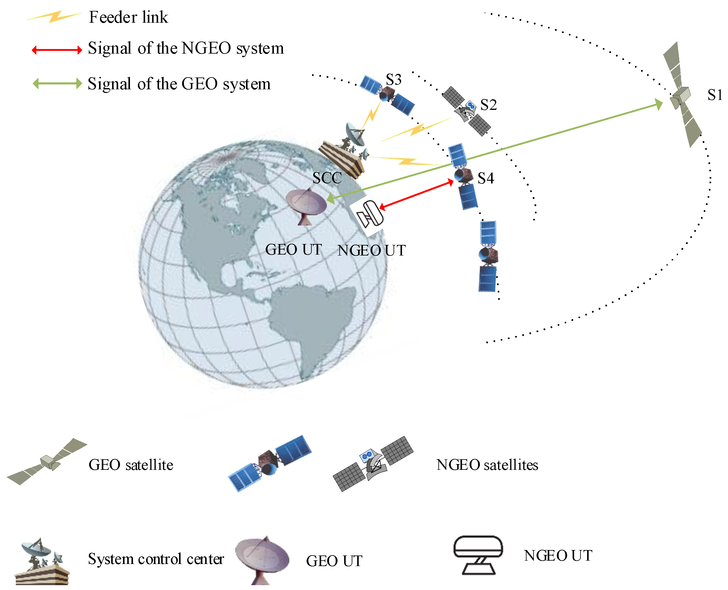
2.1. Multi-Layer Satellite System

As depicted in Figure 1, a co-frequency three-tier satellite system is considered wherein the GEO satellite and its UT are communicated with fixed links, NGEO UTs can flexible access the two-tier NGEO satellite networks controlled by a system control center (SCC) via Feeder link. Specifically, the SCC oversees and manages the system status, handling access control and allocating communication resource. Typically, GEO Satellite S1 operates as a non-cooperative satellite with communication priority, whereas S2, S3, and S4 operate in different non-stationary orbits within the NGEO system. Notably, S3 and S4 share the same orbit, while S2 is positioned in a higher orbit than S3. The satellite position at GEO is fixed, with the GEO UT positioned at the system’s origin.
We consider single-beam antenna satellites, with the beam center of the NGEO satellite aligned with the core of Earth, disregarding the effects of beamforming. In the Ku/Ka band, the high gain directional antenna is widely used for the NGEO UT/satellite to compensate for large-scale fading. In-line interference, however, is the side effect when directed to the GEO system. We assume that NGEO UT has multiple beams for tracking the targeted satellites (i.e., S2–S4) and can accordingly align its boresight to the satellite for optimal transmission.

2.2. Geometry Model Based on Geocentric Angle

Traditionally, models for terrestrial heterogeneous systems (THS) and UAV-aided THS rely on omnidirectional antennas, where the received signal power is predominantly determined by transmit power and the Euclidean distance between user terminal (UT) and base stations (BS). However, satellite systems necessitate directional antennas due to significant propagation losses over vast transmission distances spanning thousands of kilometers. The performance of such directional antennas is intricately influenced by the angle away from the prime orientation, presenting a challenge in accurately modeling multi-layer satellite systems (MSS) due to the nuanced relationship between distance and off-axis angle.
The model presented for the NGEO MSS, as illustrated in Figure 2, is rooted in stochastic geometry structures. Specifically, let r k , ϑ , ζ : r k = r E + H k , 0 ϑ ϑ max , 0 ζ 2 π denote the coordinates in R 3 spherical surface, wherein r E denotes the Earth radius, ϑ represents the angular offset from the axis of the line O G connecting the Earth core to the GEO satellite, ζ denotes the rotation angle and H k represents the k-th layer sphere’s altitude. We account for the potential interference of NGEO UTs with a GEO UT within a finite zone and model the geometry range above the horizon of the GEO UT, as depicted in Figure 2, the maximum off-axis angle ϑ max is given by
ϑ max = arccos r E r E + H k ,
where arccos · represents the trigonometrical function.
In light of the employment of directional antennas by the NGEO UTs, we presuppose no mutual interference between them. Furthermore, it is postulated that the operational range of NGEO UTs aligns with the identical maximum off-axis angle, designated as ϑ max , as those of the NGEO satellites. The uniformly distributed Bernoulli point process (BPP) surpasses the Poisson point process (PPP) for approximating the global satellite system [19], where the number of satellites is finite and static. Nonetheless, the scenario examined in our manuscript involves a finite domain and the number of observable satellites fluctuates dynamically due to the Earth/satellite mobility. Thus, the approximation methodology for global satellite system is inadequate for our scenario. Subsequently, the positions of NGEO UTs and satellites encapsulated within a designated region are simulated utilizing three-tier concentric spherical PPPs, denoted by Φ E and Φ k , respectively, with corresponding densities [20]
ρ E = N U 4 π r E 2 ,
ρ k = N S , k 4 π r k 2 ,
where N U and N S , k are the number of UTs and k-th tier satellites, respectively.
For convenience, let us place a typical GEO satellite and its corresponding UT positioned on the axis O G within Figure 2, treating it as the off-axis angle’s origin. Using basic geometry, the angle θ of a NGEO satellite antenna, related to the geocentric angle ϑ ^ k , is expressed as
θ ϑ ^ k = arcsin r E sin ϑ ^ k d ϑ ^ k ,
where ϑ ^ k represents the geocentric angular between the UT and a satellite of k-th tier and the distance of that is
d ϑ ^ k = r E + H k 2 + r E 2 2 r E r E + H k cos ϑ ^ k .
By utilizing (4) and (5), we can elucidate the gain G ( θ ) of the antenna and the separation between satellite and UT using the geocentric angle ϑ ^ k for NGEO satellites.
Similar to the approach in [18], NGEO satellites are restricted from communicating within the exclusion zone. Let α U , α D denote the exclusion angle of uplink and downlink, respectively. The corresponding off-axis angle ϑ 0 l , l U , D of the axis O G can then be expressed as
ϑ 0 l = α l + arcsin r E sin α l r E + H k .
Without loss of generality, such as the geocentric angle P O Q depicted as ϑ ^ k in Figure 2, this could alternatively be denoted as
ϑ ^ k = arccos O P O Q O P O Q = arccos sin ϑ k sin ϑ E cos ζ k ζ E + cos ϑ k cos ϑ E ,
where ϑ E and ϑ k represent the off-axis angles of the axis O G for the UT and a satellite of k-th tier, respectively, with rotation angles ζ E and ζ k . Based on (7), the representation of a spherical surface can be succinctly conveyed through the use of the geocentric angle.

2.3. Propagation Model

Utilizing the basic large-scale propagation characteristics of the satellite-terrestrial channel, the channel coefficient h k linking the satellite with the UT can be represented by
h k = c 0 4 π f c d k ϑ ^ G UT φ G k Sat θ κ B T 1 / 2 h ,
where f c represents the carrier frequency; c 0 signifies the light speed; κ stands for Boltzmann constant; B represents the bandwidth of the signal; T corresponds to the noise temperature of the receiver. Furthermore, G UT ( φ ) denotes the antenna gain of the UT with respect to the off-axis angle φ and G k Sat ( θ ) refers to the antenna gain of a satellite with regard to the off-axis angle θ . h represents the coefficient of the small-scale fading and follows a shadowed Rician (SR) distribution. The probability density function (PDF) of h is represented by the following:
f h 2 x = 2 n p c 2 n p c + V n 1 2 p c exp x 2 p c F 1 1 n , 1 , V x 2 p c 2 n p c + V .
In the above, F 1 1 ( · , · , · ) represents the hypergeometric function, while n, pc, and V denote the Nakagami fading coefficient, half-power of the scattering component, and half-power of the direct path, respectively. According to ITU-R. S. 672-4 [21], the antenna pattern of the GEO satellite is given by
G GEO Sat θ = G max 0 < θ θ 3 d B G max 3 ( θ / θ 3 dB ) 2 θ 3 dB < θ Y 1 θ 3 dB G max + L s Y 1 θ 3 dB < θ Y 2 θ 3 dB G max + L s + 20 25 log θ / θ 3 dB Y 2 θ 3 dB < θ θ 1 0 θ 1 < θ , ( dBi )
where θ 3 dB is the angle corresponding to the half of the maximum gain, Ls = −25, Y 1 = 2.887 , and Y2 = 6.32. G max = 10log(η(πDf/c)2) is the antenna maximum gain, where η and D are the antenna efficiency and the antenna diameter, respectively. The antenna pattern of the NGEO satellite is obtained from ITU-R. S. 1528 [22] as
G NGEO Sat θ = G max 0 < θ θ 3 dB G max 3 ( θ / θ 3 dB ) 2 θ 3 dB < θ Y 3 G max + L s 25 log θ / θ 3 dB Y 3 < θ Y 4 L F Y 4 < θ , ( dBi ) .
In the above, Y3 = θ3dB(−Ls/3)1/2, Y4 = Y3100.04(Gmax+Ls+LF) and LF = 5. Based on ITU-R. S. 465-6 [23] and ITU-R. S. 1428 [24], the antenna pattern of GEO UT and NGEO UT are, respectively, given by
G GEO UT θ = G max 0 < θ θ t 32 25 log θ θ t < θ 48 ° 10 48 ° < θ , ( dBi ) .
G NGEO UT θ = G max 2.5 × 10 3 D λ 2 0 < θ θ m G max 25 log 95 λ D θ m < θ 95 λ D G max 25 log θ 95 λ D < θ 33.1 ° 9 33.1 ° < θ 80 ° 4 80 ° < θ 120 ° 9 120 ° < θ 180 ° , ( dBi ) .
where θt = max(2°, 144(D/λ)−1.09) and θ m = 20 λ / D G max ( 29 25 log ( 95 λ D ) ) are the threshold parameters; λ is the wavelength.

3. The Proposed Decoupling Uplink and Downlink Access Scheme

3.1. Signal Interference Noise Ratio

Assume that a typical NGEO UT u0 is served by the satellite k0 from the k-th tier, To mitigate the ping-pong effect during the association process, we employ the expectation of the received signal power
E S u 0 , k 0 UP = E P n , UT h u 0 2 = P n , UT 2 c 0 + V Z u 0 ϑ ^ k 0 ,
E S u 0 , k 0 Down = E P k h u 0 2 = P n , UT 2 c 0 + V Z u 0 ϑ ^ k 0 ,
as the access criterion, where 2pc + V is value of E [ | h | 2 ] and
Z u i ϑ ^ = G n UT G n Sat θ ϑ ^ k d u i 2 ϑ ^ ,
then the SINR for uplink communication is given by
S I N R u 0 , k 0 UP = P n , UT h u 0 2 u i Φ E u 0 P n , UT h u i 2 + P g , UT h g , UT 2 + σ 2 = P n , UT Z u 0 ϑ ^ u 0 u i Φ E u 0 P n , UT Z u i ϑ ^ u i + P g , UT d g 2 G g UT G n Sat + σ 0 2 ,
where k ∈ {1, …, K} subscripts g and n representing the GEO and NGEO systems, respectively. Furthermore σ 2 and σ 0 2 , stand for the noise power and equivalent noise power, respectively. The SINR at u0 of the downlink and its corresponding satellite k1 (or k0) can be represented as
S I N R u 0 , k 1 Down = P k h k 1 2 k i Φ k k 1 P k h k i 2 + v j Φ v P v h v j 2 + P g h g 2 + σ 2 = P k Z k 1 ϑ ^ k 1 k i Φ k k 1 P k Z k i ϑ ^ k i + v j Φ v P v Z v j ϑ ^ v j + P g d g 2 G n UT G g Sat + σ 0 2 ,
where i { 1 , , K } / { k } ; h k i (or h v i ) is the channel coefficient of the UT u0 and satellite ki (or vj), respectively.

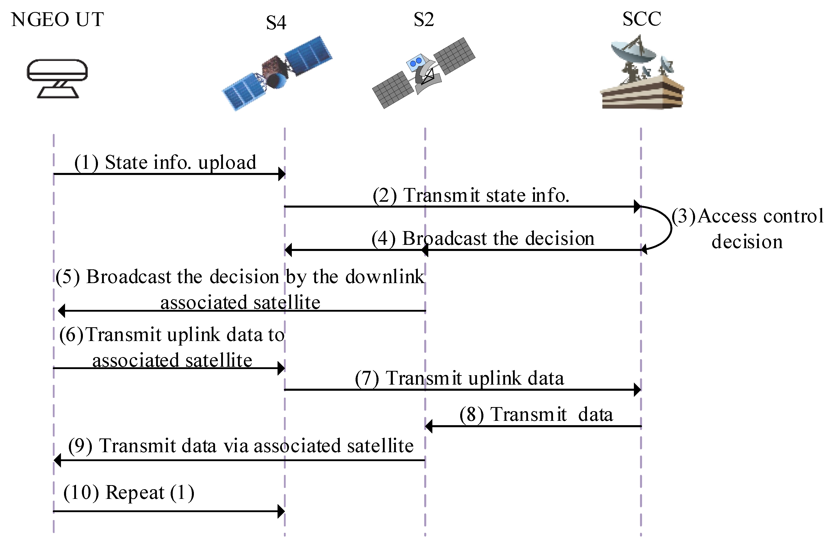
3.2. DUDA Protocol for Centralized Network Systems

Without loss of generality, we consider two-tier satellites, i.e., k ∈ {L, H}. Let ϑ L 0 and ϑ h 0 represent the off-axis angle of two typical NGEO satellites belonging to different tiers. Without loss of generality, we consider a scenario with two tiers of satellites, denoted as k ∈ {L, H}. Let ϑ L 0 and ϑ H 0 represent the off-axis angles of two typical NGEO satellites belonging to different tiers.
Within the proposed DUDA scheme, NGEO UTs invariably opt for the satellite exhibiting the maximum uplink SINR for uplink transmission. Similarly, these same NGEO UTs select the intended satellite boasting the peak downlink SINR for their downlink transmission. Thus, we can distinguish between four distinct scenarios: (a) Both link transmissions of the NGEO UT are accessed via S a t L . (b) Both link transmissions of the NGEO UT are accessed via S a t H . (c) The uplink of the NGEO UT is directly connected to S a t L while the downlink utilizes S a t H . (d) The uplink transmission of the NGEO UT is linked to S a t H while the downlink utilizes S a t L . These scenarios (a)–(d) correspond to four mathematical expressions, outlined as follows
  • Case 1: Both access S a t L in UL and DL:
    { Z u 0 , L ( ϑ ^ L 0 ) Z u 0 , H ( ϑ ^ H 0 ) > P H P L Z u 0 , L ( ϑ ^ L 0 ) Z u 0 , H ( ϑ ^ H 0 ) > 1 } .
  • Case 2: Both access S a t H in UL and DL
    { Z u 0 , L ( ϑ ^ L 0 ) Z u 0 , H ( ϑ ^ H 0 ) < P H P L Z u 0 , L ( ϑ ^ L 0 ) Z u 0 , H ( ϑ ^ H 0 ) < 1 } .
  • Case 3: Access S a t L in UL while access S a t H in DL
    { Z u 0 , L ( ϑ ^ L 0 ) Z u 0 , H ( ϑ ^ H 0 ) < P H P L Z u 0 , L ( ϑ ^ L 0 ) Z u 0 , H ( ϑ ^ H 0 ) > 1 } .
  • Case 4: Access S a t H in UL while access S a t L in DL
    { Z u 0 , L ( ϑ ^ L 0 ) Z u 0 , H ( ϑ ^ H 0 ) > P H P L Z u 0 , L ( ϑ ^ L 0 ) Z u 0 , H ( ϑ ^ H 0 ) < 1 } .
From the perspective of routing, the DUDA scheme decouples the route table between uplink and downlink transmission. The centralized network framework is considered to facilitate the route table update. The rule of routing first hop, constrained by the SINR and the exclusion zones, is proposed as the DUDA scheme. The standard procedure of the DUDA protocol is encapsulated in Figure 3. The state data of step (1) incorporate the UT location and channel state information (CSI). Through the relay of the satellite, the SCC computes Z u 0 , L ( ϑ ^ L 0 ) Z u 0 , H ( ϑ ^ H 0 ) and Z u 0 , L ( ϑ ^ L 0 ) Z u 0 , H ( ϑ ^ H 0 ) to determine the associated satellites for uplink and downlink access. The UT is informed by the associated satellite in downlink, subsequently, the UT transmits uplink data inclusive of confirm information and UT data to the associated satellite in uplink. The access process concludes and repeats periodically. It is straightforward to execute this strategy in MSS as the SCC can be the ground station or a satellite.

3.3. Performance Analysis

The association performance analysis of the proposed DUDA scheme is conducted based on stochastic geometry. Initially, the specific number of satellites located within a finite region R of the PPP with density ρ k is given by
Pr N = n = 1 n ! ρ k R n exp ρ R ,
where R = 2 π r E + r k 2 1 cos ϑ is the area of the spherical dome. Let n = 0 and substitute (3) into (23), then the cumulative distribution function (CDF) of the geocentric angle ϑ 0 can be approximated as [20]
F ϑ 0 ϑ 1 exp N k 2 1 cos ϑ .
Then, the PDF of the geocentric angle is obtained as
f ϑ 0 ϑ = N k 2 sin ϑ exp 1 cos ϑ .
Given the UT position as the reference point, ϑ ^ also follows the above PDF. Assume that P H > P L ; then, the association probability for these cases are calculated as
Pr Case 1 = Pr Z u 0 , L ( ϑ ^ L 0 ) > P H P L Z u 0 , H ( ϑ ^ H 0 ) = 1 F Z u 0 , H P H P L z L f Z u 0 , L z L d x L ,
Pr Case 2 = Pr Z u 0 , L ( ϑ ^ L 0 ) < Z u 0 , H ( ϑ ^ H 0 ) = F Z u 0 , H z L f Z u 0 , L z L d x L ,
Pr Case 3 = Pr Z u 0 , H ( ϑ ^ H 0 ) < Z u 0 , L ( ϑ ^ L 0 ) < P H P L Z u 0 , H ( ϑ ^ H 0 ) = F Z u 0 , H P H P L z L 1 F Z u 0 , H z L f Z u 0 , L z L d x L ,
Pr Case 4 = Pr P H P L Z u 0 , H ( ϑ ^ H 0 ) < Z u 0 , L ( ϑ ^ L 0 ) < Z u 0 , H ( ϑ ^ H 0 ) = 0 ,
where F Z u 0 , H · and f Z u 0 , L · are CDF and PDF of (16). We utilize the Monte Carlo method to obtain them due to the inverse function in (16) is not closed-form. We further appraise the transmission rate as a benchmark of performance, which is obtained by
R l = B log 2 1 + S I N R l ,
where l { U , D } . Then, the throughput capacity of the NGEO system is obtained by
R total = u p Φ E B log 1 + S I N R u p D + k q Φ k B log 1 + 1 S I N R k q U ,
and
1 S I N R k q U = S I N R k q U , UT access k q in UL 0 , others .

4. DUDA Scheme for Interference Avoidance

4.1. Interference Avoidance Criteria

The NGEO satellites, being dynamic and positioned at much lower orbital altitudes compared to the GEO satellite in MSS, pose a significant challenge during in line with the GEO satellite. The downlink signal of a NGEO satellite can severely interfere with the GEO UT. Typically, the antenna gain of the NGEO satellite main lobe is approximately tens of dB, significantly degrading the downlink communication quality of the GEO satellite system. Therefore, in-line interference avoidance is imperative for multi-layer satellite systems.
We commence by analyzing the fundamental criteria of the interference avoidance employed in the DUDA system, which formulates whether or not an NGEO satellite can gain access by the UTs. In other words, if the NGEO satellites fall outside the interference avoidance zone, the satellites possessing the highest SINR will consequently be selected for access to the UTs, and vice versa. When discussing uplink transmission, it is crucial to acknowledge that NGEO UTs have a fixed transmission power and must attain a minimum 35,786 km propagation distance. Given such constraints, uplink interference poses fewer challenges compared to downlink transmission. We postulate that α U will always be lesser than α D , thereby implying ϑ 0 U will be smaller than ϑ 0 D . Consequently, the interference avoidance guidelines for DUDA in relation to NGEO satellites can be summarized as follows
can not be accessed , ϑ k i ϑ 0 U
only uplink can be accessed , ϑ 0 U < ϑ k i ϑ 0 D
Both links can be accessed , ϑ 0 U < ϑ k i ϑ 0 D .
Based on (32b), the innovative DUDA scheme offers considerable protection to the uplink transmission, thereby providing additional accessible satellites for enhanced performance of the MSS service.

4.2. Satellite Association

Given a typical moment, a satellite may reside in the exclusion area for uplink, the exclusion area for both links, or the areas without interference avoidance. Utilizing the satellite’s exact position, we can classify its positioning into a total of five distinct scenarios: (a) Both satellites reside entirely within the exclusion zone for both links. (b) Both satellites fall within the confines of the exclusion zone for downlink, with at least one satellite not overlapping within either the exclusion zone for both links. (c) One satellite is situated within the exclusion zone for both links, whilst the second is positioned within the normal zone. (d) One satellite remains in the exclusion zone for downlink, whilst the second is situated within the normal zone. (e) Both satellites are occupying positions within the normal zone. These distinctive (a)–(e) position-based situations align with the four access scenarios delineated by (32), as illustrated below:
Case 1: Failed access
max ϑ L 0 , ϑ H 0 ϑ 0 U ,
which emerges when (a) happens and both satellites in exclusion zone are not accessible stipulated by (32a).
Case 2: UT connected to marked satellites solely in uplink,
ϑ H 0 > ϑ 0 U ϑ L 0 > ϑ 0 U ; max ϑ L 0 , ϑ H 0 < ϑ 0 D ,
which corresponds with situation (b) exclusively. It is a distinctive characteristic of the DUDA platform as distinguished from DUCA, which does not permit individual link access.
Case 3: Decoupling uplink and downlink access, i.e.,
ϑ 0 U < min ϑ L 0 , ϑ H 0 ϑ 0 D ; max ϑ L 0 , ϑ H 0 > ϑ 0 D min ϑ L 0 , ϑ H 0 > ϑ 0 D ; Z L 0 ϑ ^ L 0 Z H 0 ϑ ^ H 0 > P H P L Z L 0 ϑ ^ L 0 Z H 0 ϑ ^ H 0 1 Z L 0 ϑ ^ L 0 Z H 0 ϑ ^ H 0 P H P L Z L 0 ϑ ^ L 0 Z H 0 ϑ ^ H 0 > 1 .
Situations (d) and (e) align with this case. In MSS, the significance of decoupling operation lies in two aspects. Firstly, it involves the disparity between the average power of received signals, a principle akin to that of THS. Secondly, situation (c) arises from interference avoidance, wherein certain satellites can solely receive uplink signals, necessitating the transmission of downlink signals through another satellite. Therefore, (35) comprises the union of two components, with the former describing situation (d) and the latter representing situation (e). For an exhaustive comprehension, we recommend consulting the derivations in [10,12].
Case 4: UT connected to a satellite for both links, i.e.,
min ϑ L 0 , ϑ H 0 < ϑ 0 U ; max ϑ L 0 , ϑ H 0 > ϑ 0 D min ϑ L 0 , ϑ H 0 > ϑ 0 D ; Z L 0 ϑ ^ L 0 Z H 0 ϑ ^ H 0 P H P L Z L 0 ϑ ^ L 0 Z H 0 ϑ ^ H 0 1 Z L 0 ϑ ^ L 0 Z H 0 ϑ ^ H 0 > P H P L Z L 0 ϑ ^ L 0 Z H 0 ϑ ^ H 0 > 1 .
The derivation of (36) accounts for situations (c) and (e). Situation (c) denotes the presence of an inaccessible satellite alongside a normal one, resulting in the UT communicating with a normal satellite for both links. As for situation (e), the latter segment of (36) serves as Case 3’s complement.

5. Simulation Results

5.1. Parameters Setting

In simulations, the value of the Boltzmann constant is 1.380649 × 10 23 J/K, the speed of light is 3 × 10 8 m/s, the Earth’s radius is 6371 km, and the GEO satellite altitude is 35,786 km. The noise temperature is same with [17], implying 300 K for the GEO UT. The remaining system parameters are detailed in Table 1. Simulation results are the expected results of channels following 1000 random generations.

5.2. Baseline

Let us introduce the in-line interference mitigation technique employed by DUCA. In this scheme, an exclusion angle α 0 is delineated as the most significant intersection of α U and α D . The interference avoidance rule of DUCA is explicitly outlined by
can not be accessed , ϑ k i ϑ 0 both links can be accessed , ϑ 0 < ϑ k i ϑ max .
The satellite association rule for DUCA is segmented into two scenarios, as follows: Case 1: Failed access. The condition of exclusion angle for Case 1 is the same with (33). Case 2: Successful access for both links,
min ϑ L 0 , ϑ H 0 < ϑ 0 U ; max ϑ L 0 , ϑ H 0 > ϑ 0 D min ϑ L 0 , ϑ H 0 > ϑ 0 D .

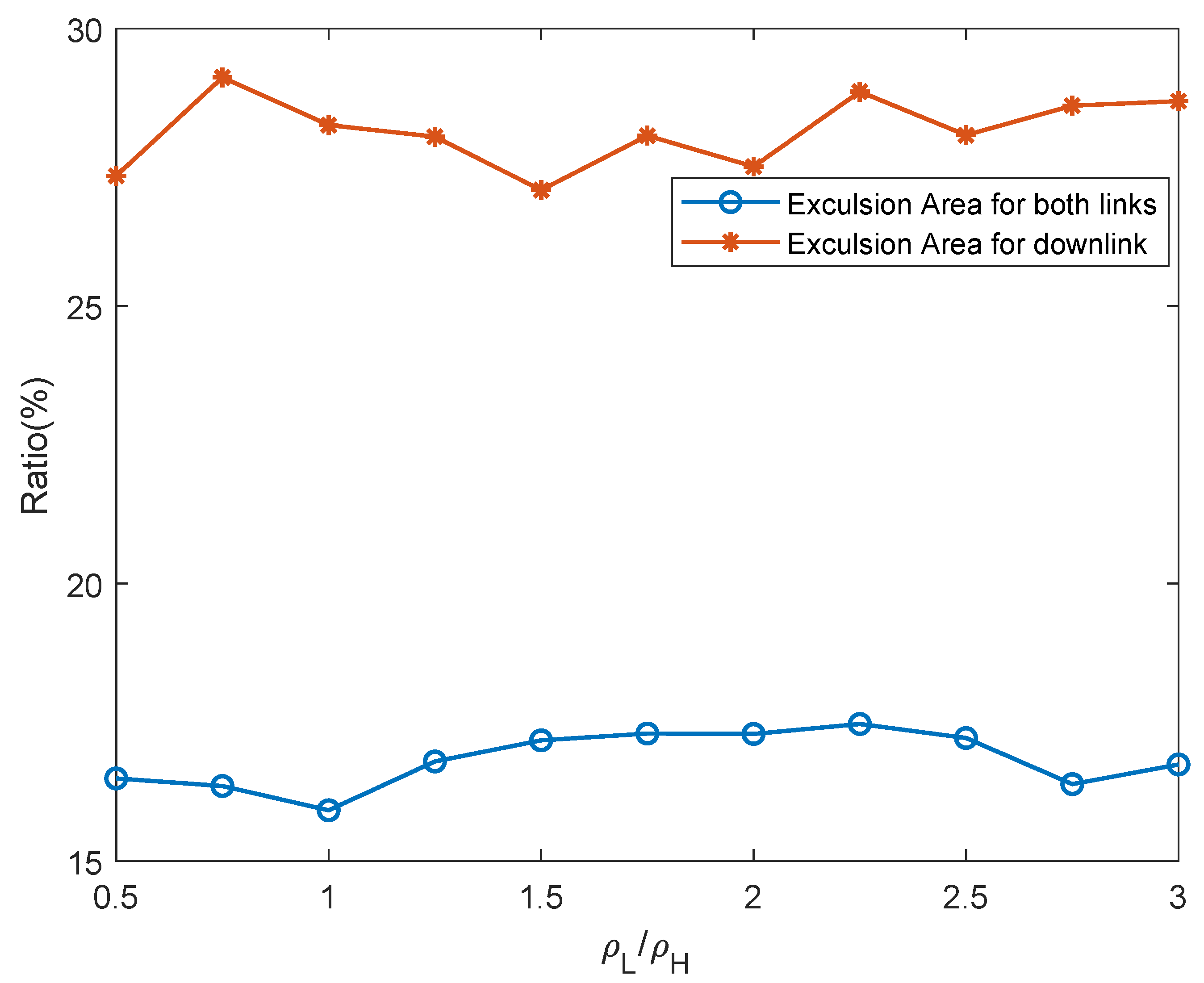
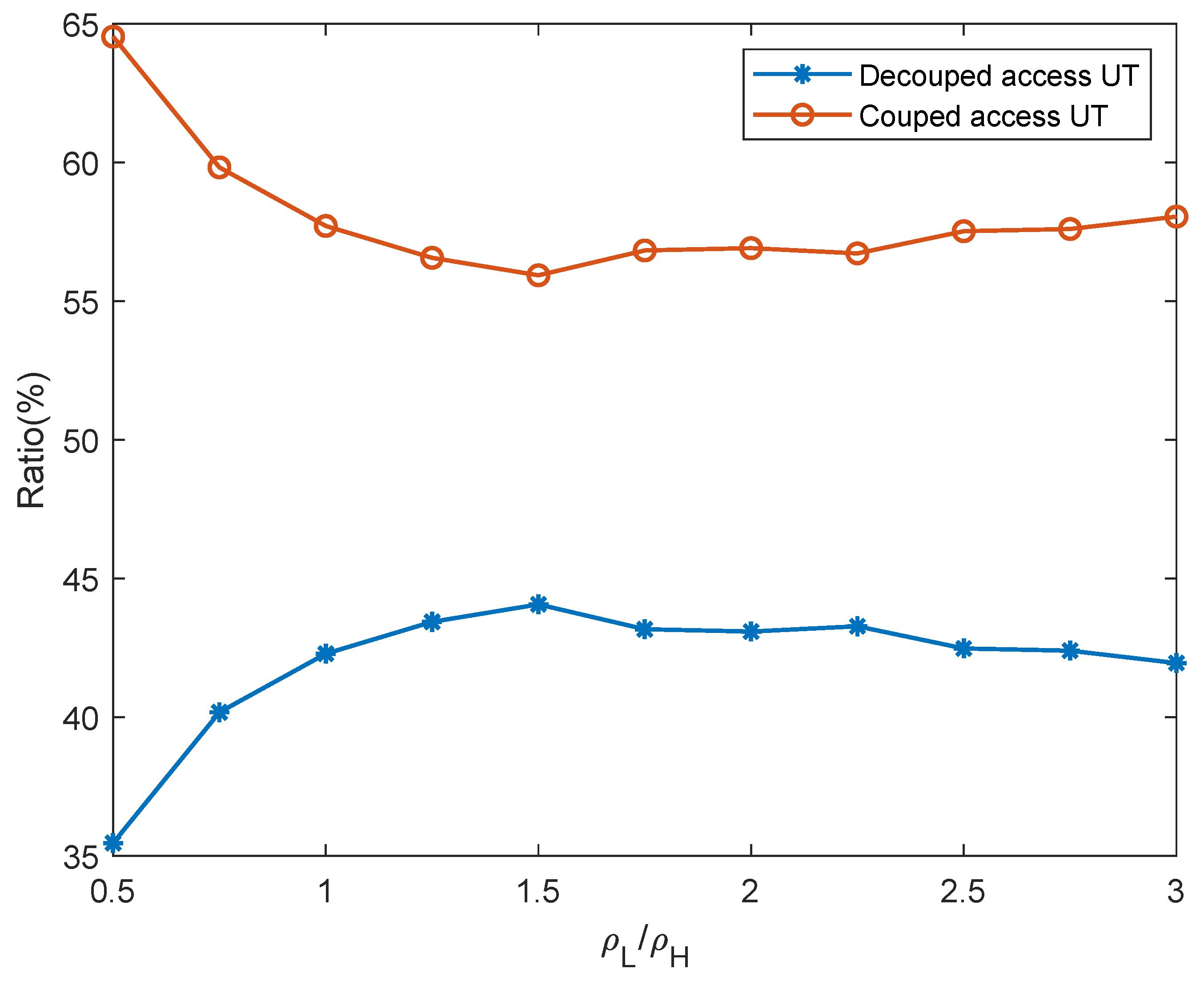
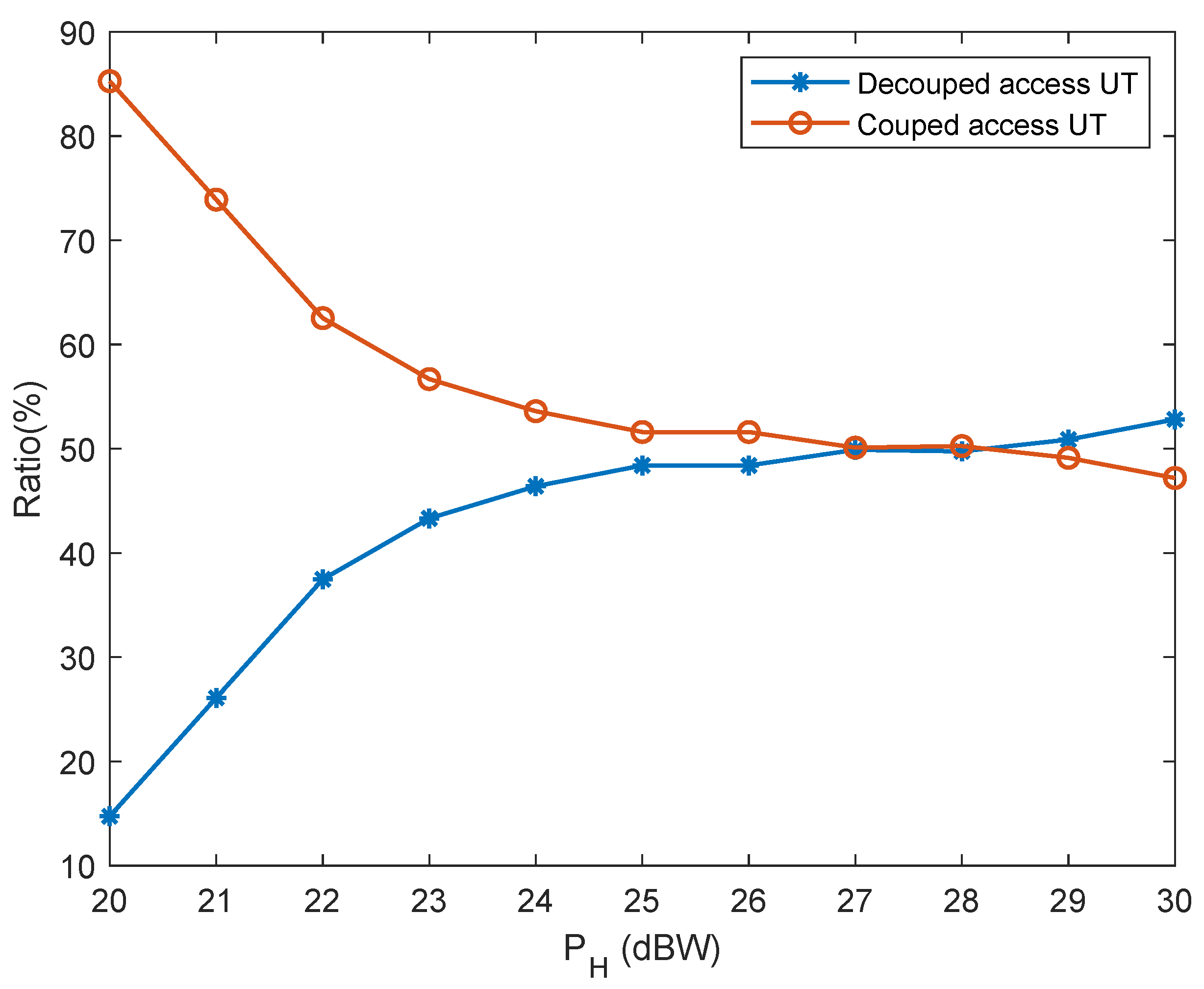
5.3. Probability Results

As depicted in Figure 4, it is apparent that approximately 28 percent of the NEO satellites are located within the uplink exclusion region, whilst approximately another 16.5 percent fall under the joint uplink and downlink exclusion zone. It is notable that the likelihood of occupying this exclusion area remains relatively consistent. Moreover, it can be observed that approximately 16.5 percent of the NGEO satellites have the capability of utilizing accessible uplinks within the inline interference avoidance area. This proportion remains stable despite an increase in the number of satellites.
As illustrated in Figure 5, the quantity of decoupled access UTs attains its peak value at ρ L / ρ H = 1.5 , subsequently diminishing gradually as ρ L / ρ H escalates. This is due to the downlink SINR of the L-th layer satellite progressively surpasses that of the H-th layer satellites; hence, the ratio of case 1 augments.
Figure 6 accentuates that the quantity of coupled access UTs enhances with augmenting P H . Consequently, if the H-th layer satellites possess elevated transmission power, the likelihood of downlink and uplink decoupling tends to escalate. We discern from this figure that the probability of case 3 will not exhibit substantial growth when P H > 26 dBW.

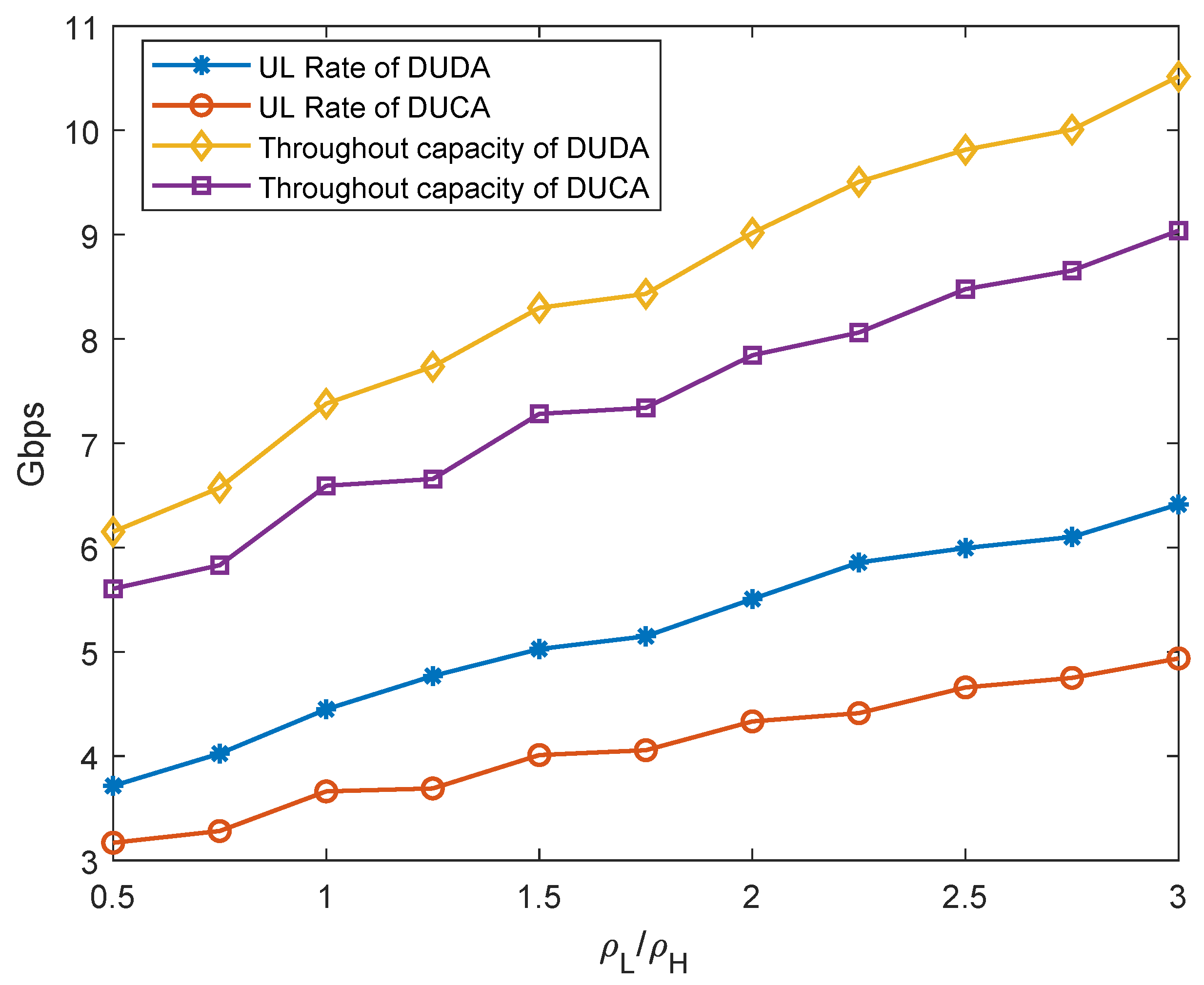
5.4. Comparison of the Throughout Capacity

As depicted in Figure 7, a comparison of transmission rate performance is made between DUDA and DUCA. Figure 7 reveals that the DUDA system’s throughput capacity achieves a maximum value of about 10 Gbps at ρ L ρ H = 3 , while in comparison, utilizing DUCA yields merely an operational rate of 9 Gbps. Specifically, analysis illustrated within Figure 8 underscores the superiority of DUDA, demonstrating its potential to amplify the uplink transmission speed by a significant 20 percent. Additionally, it is noteworthy that the overall system performance significantly enhances by approximately 17 percent when P H = 23 dBW is in place. Significantly, both the overall system’s efficiency as well as the rate ratio improve proportionally when the ratio ρ L ρ H increases.
Figure 8 illustrates that while the uplink rate and throughout capacity of the DUDA approach exceed those of the DUCA scheme, the uplink rate in DUDA remains invariant as P H augmentation occurs. We observe that the uplink rate of DUCA diminishes as P H escalates. This is due to the fact that the DUCA scheme selects the satellite with highest SINR in downlink as the associated satellite for both links, consequently, the uplink transmission distance is longer than that of the L-th layer satellite.

6. Conclusions

In this work, we explored the DUDA scheme for NGEO MSS, aiming to enhance the transmission performance while addressing in-line interference issues. We introduced a spherical surface model based on geocentric angle to succinctly capture the interplay between distance and antenna gain within NGEO MSS. Leveraging this model, we devised the DUDA scheme, incorporating strategies to mitigate in-line interference. Our results illustrate the substantial superiority of the proposed DUDA scheme over conventional DUCA, particularly in scenarios involving in-line interference. Notably, the uplink transmission rate experiences significant improvements without the need for additional physical resources. We also ascertain that if the density of lower orbit satellite is substantial, the decoupled access probability will diminish.
These results underscore the potential deployment of the DUDA scheme for centralized NGEO MSS. In future work, the DUDA protocol for distributed satellite networks and the decoupled criterion grounded in service demand are worthy of exploration.

Author Contributions

Methodology, Y.L. (Yilun Liu), and Y.L. (Yujie Liu); software, Y.L. (Yilun Liu) and validation, Y.L. (Yilun Liu) and Y.L. (Yujie Liu); investigation, X.K.; resources, X.K.; writing—original draft preparation, Y.L. (Yilun Liu); writing—review and editing, and X.K. All authors have read and agreed to the published version of the manuscript.

Funding

This paper was funded by the National Key R&D Program of China under Grant 2021YFB2900404, the National Key Laboratory of Wireless Communications Foundation under Grant 6142102222102 and IFN20230203, and the National Natural Science Foundation of China under Grant 62371098.

Data Availability Statement

Data are contained within the article.

Conflicts of Interest

The authors declare no conflicts of interest.

References

  1. You, X.; Wang, C.X.; Huang, J.; Gao, X.; Zhang, Z.; Wang, M.; Huang, Y.; Zhang, C.; Jiang, Y.; Wang, J.; et al. Towards 6G wireless communication systems: Vision, enabling technologies, and new paradigm shifts. Sci. China Inf. Sci. 2021, 64, 110301. [Google Scholar] [CrossRef]
  2. Centenaro, M.; Costa, C.E.; Granelli, F.; Sacchi, C.; Vangelista, L. A Survey on Technologies, Standards and Open Challenges in Satellite IoT. IEEE Commun. Surv. Tutorials 2021, 23, 1693–1720. [Google Scholar] [CrossRef]
  3. Wei, T.; Feng, W.; Chen, Y.; Wang, C.X.; Ge, N.; Lu, J. Hybrid Satellite-Terrestrial Communication Networks for the Maritime Internet of Things: Key Technologies, Opportunities, and Challenges. IEEE Internet Things J. 2021, 8, 8910–8934. [Google Scholar] [CrossRef]
  4. Ahmed, A.; Al-Dweik, A.; Iraqi, Y.; Damiani, E. Integrated Terrestrial-Wired and LEO Satellite With Offline Bidirectional Cooperation for 6G IoT Networks. IEEE Internet Things J. 2024, 11, 15767–15782. [Google Scholar] [CrossRef]
  5. Zhang, Y.; Ni, W.; Mao, Y.; Ning, B.; Xiao, S.; Tang, W.; Niyato, D. Rate-Splitting Multiple Access for Covert Communications. IEEE Wirel. Commun. Lett. 2024, 13, 1685–1689. [Google Scholar] [CrossRef]
  6. Bing, L.; Gu, Y.; Hu, L.; Aulin, T.; Yin, Y.; Wang, J. QoS Provision for Industrial IoT Networking: Multiantenna NOMA Based on Partial CSIT. IEEE Trans. Ind. Inform. 2024, 20, 8239–8250. [Google Scholar] [CrossRef]
  7. Elshaer, H.; Boccardi, F.; Dohler, M.; Irmer, R. Downlink and Uplink Decoupling: A disruptive architectural design for 5G systems. In Proceedings of the 2014 IEEE Global Communications Conference, Austin, TX, USA, 8–12 December 2014; pp. 1798–1803. [Google Scholar]
  8. Boccardi, F.; Andrews, J.; Elshaer, H.; Dohler, M.; Parkvall, S.; Popovski, P.; Singh, S. Why to decouple the uplink and downlink in cellular systems and how to do it. IEEE Commun. Mag. 2016, 54, 110–117. [Google Scholar] [CrossRef]
  9. Smiljkovikj, K.; Popovski, P.; Gavrilovska, L. Analysis of the Decoupled Access for Downlink and Uplink in Wireless Heterogeneous Networks. IEEE Wirel. Commun. Lett. 2015, 4, 173–176. [Google Scholar] [CrossRef]
  10. Bacha, M.; Wu, Y.; Clerckx, B. Downlink and Uplink Decoupling in Two-Tier Heterogeneous Networks With Multi- Antenna Base Stations. IEEE Trans. Wirel. Commun. 2017, 16, 2760–2775. [Google Scholar] [CrossRef]
  11. Zhang, L.; Nie, W.; Feng, G.; Zheng, F.C.; Qin, S. Uplink Performance Improvement by Decoupling Uplink/Downlink Access in HetNets. IEEE Trans. Veh. Technol. 2017, 66, 6862–6876. [Google Scholar] [CrossRef]
  12. Arif, M.; Wyne, S.; Navaie, K.; Nawaz, S.J.; Alvi, S.H. Decoupled Downlink and Uplink Access for Aerial Terrestrial Heterogeneous Cellular Networks. IEEE Access 2020, 8, 111172–111185. [Google Scholar] [CrossRef]
  13. Shi, Y.; Alsusa, E.; Baidas, M.W. Downlink-Uplink Decoupled Access in Heterogeneous Cellular Networks with UAVs. In Proceedings of the 2020 IEEE 31st Annual International Symposium on Personal, Indoor and Mobile Radio Communications, London, UK, 31 August–3 September 2020; pp. 1–6. [Google Scholar]
  14. Veeravalli, V.; El Gamal, A. Interference Management in Wireless Networks: Fundamental Bounds and the Role of Cooperation; Cambridge University Press: Cambridge, UK, 2018. [Google Scholar]
  15. Sharma, S.K.; Chatzinotas, S.; Ottersten, B. In-line interference mitigation techniques for spectral coexistence of GEO and NGEO satellites. Int. J. Satell. Commun. Netw. 2016, 34, 11–39. [Google Scholar] [CrossRef]
  16. Pourmoghadas, A.; Sharma, S.K.; Chatzinotas, S.; Ottersten, B. On the apectral coexistence of GSO and NGSO FSS systems: Power control mechanisms and a methodology for inter-site distance determination. Int. J. Satell. Commun. Netw. 2016, 35, 443–459. [Google Scholar] [CrossRef]
  17. Zhang, C.; Jiang, C.; Kuang, L.; Jin, J.; He, Y.; Han, Z. Spatial Spectrum Sharing for Satellite and Terrestrial Communication Networks. IEEE Trans. Aerosp. Electron. Syst. 2019, 55, 1075–1089. [Google Scholar] [CrossRef]
  18. Wang, H.; Wang, C.; Yuan, J.; Zhao, Y.; Ding, R.; Wang, W. Coexistence Downlink Interference Analysis Between LEO System and GEO System in Ka Band. In Proceedings of the 2018 IEEE/CIC International Conference on Communications in China (ICCC), Beijing, China, 16–18 August 2018; pp. 465–469. [Google Scholar]
  19. Wang, R.; Kishk, M.A.; Alouini, M.S. Evaluating the Accuracy of Stochastic Geometry Based Models for LEO Satellite Networks Analysis. IEEE Commun. Lett. 2022, 26, 2440–2444. [Google Scholar] [CrossRef]
  20. Al-Hourani, A. An Analytic Approach for Modeling the Coverage Performance of Dense Satellite Networks. IEEE Wirel. Commun. Lett. 2021, 10, 897–901. [Google Scholar] [CrossRef]
  21. ITU-R S.672-4. Satellite Antenna Radiation Pattern for Use as a Design Objective in the Fixed-Satellite Service Employing Geostationary Satellites. January 2010. Available online: https://www.itu.int/rec/R-REC-S.672/en (accessed on 12 August 2024).
  22. ITU-R S.1528. Satellite Antenna Radiation Patterns for Nongeostationary Orbit Satellite Antennas Operating in the Fixed Satellite Service Below 30 GHz. 2001. Available online: https://www.itu.int/rec/R-REC-S.1528/en (accessed on 12 August 2024).
  23. ITU-R S.465-6. Reference Radiation Pattern for Earth Station Antennas in the Fixed-Satellite Service for Use in Coordination and Interference Assessment in the Frequency Range from 2 to 31 GHz. January 2010. Available online: https://www.itu.int/rec/R-REC-S.465/en (accessed on 12 August 2024).
  24. ITU-R S.1428. Reference FSS Earth Station Radiation Patterns for Use in Interference Assessment Involving Non-GSO Satellite in Frequency Bands between 10.7 GHz and 30 GHz. 2000. Available online: https://www.itu.int/dms_pubrec/itu-r/rec/s/R-REC-S.1428-1-200102-I!!PDF-E.pdf (accessed on 12 August 2024).
Figure 1. The system diagrammatic sketch.
Electronics 13 03245 g001
Figure 2. The architecture of the NGEO MSS comprises several key components: a GEO satellite (denoted by the black point G), a GEO user terminal (UT) represented by the green point D, a NGEO UT depicted by the orange point Q, and k-th tier NGEO satellites denoted by the red and purple points M, N, and P. The red points denote satellites positioned within the visible area, while the purple point corresponds to a satellite outside the scope of this work, residing in a non-visible region.
Electronics 13 03245 g002
Figure 3. The DUDA protocol for centralized network systems.
Electronics 13 03245 g003
Figure 4. Probability of satellite locations.
Electronics 13 03245 g004
Figure 5. Association probability with P H = 23 dBW and P L = 20 dBW.
Electronics 13 03245 g005
Figure 6. Association probability with ρ L / ρ H = 2 .
Electronics 13 03245 g006
Figure 7. Throughout capacity of DUDA and DUCA, P H = 23 dBW and P L = 20 dBW.
Electronics 13 03245 g007
Figure 8. Throughout capacity of DUDA and DUCA, ρ L / ρ H = 2 .
Electronics 13 03245 g008
Table 1. Simulation Parameters.
ItemsValues
Carrier frequency for uplink30 GHz
Carrier frequency for downlink20 GHz
Signal bandwidth10 MHz
Maximum antenna gain of the GEO satellite47 dBi
Maximum antenna gain of the GEO UT41 dBi
Maximum antenna gain of NGEO satellites41 dBi
The mean number of the NGEO satellites ( ρ H · ϑ max )40 (H-th tier)
EIRP of the NGEO UTs54 dBW
Maximum antenna gain of the NGEO UTs37 dBi
The mean number of NGEO UTs ( ρ E · ϑ max )100
Exclusion angle for uplink ( α U ) 3
Exclusion angle for downlink ( α D ) 8
Disclaimer/Publisher’s Note: The statements, opinions and data contained in all publications are solely those of the individual author(s) and contributor(s) and not of MDPI and/or the editor(s). MDPI and/or the editor(s) disclaim responsibility for any injury to people or property resulting from any ideas, methods, instructions or products referred to in the content.

