Article

A Compact V-Band Transit Time Oscillator with Reflective Modulation Cavity

College of Advanced Interdisciplinary Studies, National University of Defense Technology, Changsha 410073, China
*
Authors to whom correspondence should be addressed.
Electronics 2024, 13(16), 3290; https://doi.org/10.3390/electronics13163290
Submission received: 24 July 2024 / Revised: 15 August 2024 / Accepted: 18 August 2024 / Published: 19 August 2024

Abstract

:
Improving compactness is essential for high-power microwave (HPM) sources. In this paper, a novel reflective modulation cavity is proposed and investigated in a V-band relativistic coaxial transit-time oscillator (RCTTO). The cold cavity analyses and particle-in-cell simulations show that the reflective modulation cavity has larger reflection coefficients of TEM mode and stronger electron beam modulation capability when compared with a uniform modulation cavity. When the input diode voltage is 391 kV, the beam current is 4.91 kA, and when the guiding magnetic field is 0.6 T, the compact V-band RCTTO produces an output microwave power of 518 MW (conversion efficiency of 27.0%). Compared with the original RCTTO, the compact V-band RCTTO featuring a reflective modulation cavity exhibits a 24.8% increase in output power and a 5.4% improvement in efficiency, and the axial length of the magnetic field uniform region is reduced by 24.2%. The compact V-band RCTTO also demonstrates a broad operation voltage range, indicating potential for stable operation with voltage fluctuations in experiments. Furthermore, the reflective modulation cavity can be integrated into other high-frequency O-type HPM devices to enhance compactness, thereby diminishing the demands on the magnetic field region, which is advantageous for the future permanent packaging of HPM sources.

1. Introduction

As required for widespread applications in high-frequency, high-power microwave (HPM), such as high-energy physics and high-power radiation [1,2,3,4], HPM sources are increasingly being developed towards higher frequency bands. Meanwhile, compactness is also an important development trend for HPM sources. Compact devices with small dimensions, light weight, and short regions for the uniform magnetic field are more suitable for practical applications. Furthermore, the short region required for the magnetic field also expands the feasibility of permanent magnetic packaging, which can further remove the energy consumption of the supply system associated with the magnetic field. Consequently, high-frequency and compact HPM sources possess great latent demand for applications.
In recent years, the research on high-frequency HPM sources and the prospect of growing applications for V-band electromagnetic radiation have led to a significant development of V-band devices [5,6,7,8]. However, the magnetic field of recent V-band devices is large, and the conversion efficiency is low [5,6,7,8]. At lower frequency bands, HPM sources that achieve high efficiency tend to have complex structures, long axial lengths, and poor compactness. Combined with practical needs, this study aims to improve the conversion efficiency and compactness of the V-band device without increasing the structural complexity.
Although many compact HPM sources have been reported, most of them are achieved by parameter optimization of their structures [9,10], and only a few have been realized by introducing special structures (e.g., all-metal metamaterial slow-wave structure) [11] or mechanisms (e.g., TEM mode feedback mechanisms) [12]. As a promising HPM source, the relativistic coaxial transit time oscillator (RCTTO) has the potential for compact design due to its advantages of low magnetic field and stable operation [13]. Typically, in high frequencies, RCTTOs adopt reflectors to prevent the TEM mode from leaking into the diode region, which can perturb the generation and transmission of the intense relativistic electron beam (IREB) [13]. Thus, the reflectors can reduce the requirement for magnetic fields and improve the beam–wave conversion efficiency. However, the drift tubes upstream and downstream of the reflector weaken the compactness of the RCTTOs. To remove the reflector while ensuring isolation of the TEM mode, this paper proposes a novel reflective modulation cavity in an RCTTO. This reflective modulation cavity combines the functions of reflecting TEM mode and modulating the electron beam’s velocity, which can shorten the axial length of the RCTTO. It is worth mentioning that the utilization of a reflective modulation cavity in an HPM oscillator has never been reported before, and this novel design of reflective modulator can also be applied to other O-type HPM devices to improve compactness.
In this paper, both electromagnetic simulation and particle-in-cell (PIC) simulation are used to investigate the reflectivity and modulation capability of the reflective modulation cavity. The reflective modulation cavity has been further applied in a novel V-band RCTTO, resulting in a 24.2% reduction in axial length and a 5.4% increase in efficiency. This demonstrates that the reflective modulation cavity ensures modulation capability while improving the compactness of the device. In Section 2, the PIC simulation results of the original V-band RCTTO are given for comparison. The design and function of the reflective modulation cavity are analyzed in Section 2. Section 4 shows typical PIC simulation results of the compact V-band RCTTO with a reflective modulator. Finally, conclusions are given in Section 5.

2. Performance of Original RCTTO

A schematic of the original RCTTO with modulation cavity is illustrated in Figure 1. The device is mainly composed of solenoid, focusing cathode, cathode cavity, reflector, uniform modulation cavity, drift cavity, extractor, and output waveguide. When a high input voltage is added, the focusing cathode emits an annular electron beam through explosive emission [14]. After entering the coaxial channel, the electron beam undergoes velocity modulation in the uniform modulation cavity [13]. After that, the velocity modulation is turned to density modulation in the drift cavity [13]. Finally, in the extractor, microwaves extract energy from the electron beam through beam–wave interaction and output through the output waveguide [13].
The simulation model is built with a PIC code CHIPIC 2.0.03 [15], which is widely used in HPM devices’ design. Different from the perfect conductor, oxygen-free copper with a conductivity of 5.99 × 10⁷ S/m is used as the conductor material in PIC simulations with the consideration of ohmic loss as in experiments [13,16,17]. When the input parameters are diode voltage 391 kV, beam current 4.91 kA, and guiding magnetic field 0.6 T, the output microwave power of the original V-band RCTTO is 415 MW, with a conversion efficiency of 21.6% (see Figure 2). The output microwave saturates at approximately 15 ns when the microwave frequency is stable at 58.69 GHz. Like a V-band RCTTO [13], the modulation cavity is designed to operate with a positive electron load conductivity, and therefore the backward power flux into the modulation cavity is important for the establishment of the electric field in the modulation cavity. Figure 3 illustrates that the backward power flux into the modulation cavity amounts to 388 MW. Meanwhile, Figure 3 also indicates that the backward power flux in the diode region is much smaller than that within the modulation cavity as the reflector isolates the leakage TEM mode. Hence, the effectiveness of the reflection can be evaluated by injecting a backward power flux (such as 388 MW) into the modulation cavity and observing the amplitude of the backward power flux that leaks into the diode region.

3. Design of Reflective Modulation Cavity

To elucidate the design principles of the reflective modulation cavity, an analysis of the modulation cavity’s operation is conducted. In RCTTO’s operation, the modulation cavity can be modeled as in Figure 4a. During the establishment of the electric field in the modulation cavity, the microwave reflected from the end of the modulation cavity determines positive feedback (R1 and R2 are the reflection coefficients of the left and right end of the modulation cavity, respectively). However, R2 should not be excessively large, otherwise it will be detrimental to the backward power flux entering the modulation cavity, resulting in a weak electric field. Therefore, in order to appropriately enhance the electric field in the modulation cavity to improve its modulation capability, increasing R1 can be a more reliable approach, which can also improve reflection capability.
The geometric structure between coaxial input channel and drift cavity (the dotted box in Figure 1) with different modulation cavities is shown in Figure 4b. The primary difference between the original modulation cavity and the reflective modulation cavity is the structure of the first gap, where the improved first gap is similar to a miniature reflector. Notably, changes to the gap structure can lead to variations in the reflection coefficients at both the left and right ports of the gap. Hence, based on the previous analysis, this paper only chooses the first gap of the modulation cavity to optimize for minimizing the impact on the device, while maintaining the original uniform structure of the other four gaps unchanged. Finally, as the reflector is removed, the distance from the input channel to the drift cavity can be significantly reduced, and the length of the drift tube preceding the modulation cavity is shortened, resulting in a more compact device.
Since the reflector is removed, the reflective modulation cavity needs to reflect the electromagnetic wave within the first gap. Therefore, the first gap’s reflection coefficient should be increased. The reflective modulation cavity’s first gap is designed similarly to the structure of the original reflector; in fact, other structures of the first gap can also be applied to increase the reflection coefficient at the operation frequency.
The reflection coefficient for TEM mode (the coaxial channel cut-off other modes) of different first gaps is obtained by the electromagnetic simulation software CST Microwave Studio 2020 [9]. As shown in Figure 5a, it can be seen that the reflection coefficient of the reflective modulation cavity’s first gap is larger than that of the uniform modulation cavity. Thus, it can be predicted that the reflective modulation cavity will have greater reflective and modulation capabilities.
The reflective modulation cavity’s first gap has a stronger reflection coefficient at lower frequencies, which means that the positive feedback to the electric field at lower frequencies is stronger, so the actual frequency of the RCTTO loaded with the reflective modulation cavity will be lower than that of the original device. Figure 5b shows the reflection coefficient of the reflective modulation cavity, which has a minimum value of 0.723 at 58.65 GHz. A lower operation frequency of the improved device with the reflective modulation cavity is found to be 58.19 GHz, corresponding to a larger reflection coefficient of 99.99%.

3.1. Reflection of TEM Mode

To confirm the reflection characteristics of the reflective modulation cavity, a TEM mode of 388 MW at 58.2 GHz is injected from the right port near the fifth gap. Figure 6 demonstrates the electric field amplitude distribution for both the uniform modulation cavity and reflective modulation cavity, showing that there is no appreciable microwave leakage from the left port of the reflective modulation cavity, whereas significant leakage occurs in the case of the uniform modulation cavity. Compared with the uniform modulation cavity, an enhanced electric field is observed in the reflective modulation cavity due to the reflection of most microwave power, which is consistent with the previous analyses. As presented in Figure 7, the leakage power from the left port of the reflective modulation cavity is approximately 16.97 W. This proves that the reflective modulation cavity’s reflection coefficient to the TEM mode is close to 100%. Meanwhile, Figure 7 also shows that the microwave power leaked from the left port of the uniform modulation cavity is approximately 7.84 MW, much larger than that of the reflective modulation cavity.
To investigate the longitudinal operation mode, Ez distribution is obtained and normalized, as shown in Figure 8. The longitudinal operation mode of the reflective modulation cavity is similar to the π mode of the five-gap uniform one, which indicates that the improved first gap does not change the longitudinal mode of the uniform one. Furthermore, the maximum electric field in the first gap in the reflective modulation cavity (20.2%) is much lower than that in the uniform modulation cavity (60.8%). The first gap is closest to the diode region among the five gaps; thus, the field strength in it should be reduced as well if the modulation cavity reflects most of the TEM mode. Therefore, it can also be deduced that the reflective modulation cavity reflects a majority of the microwaves.

3.2. Modulation of Electron Beam

In RCTTOs, the modulation cavity’s main role is to modulate the electron beam’s velocity. The modulation capability of the cavity can be assessed based on the amplitude of gap voltage and fundamental harmonic current [12]. A higher amplitude of gap voltage and fundamental harmonic current can demonstrate a stronger modulation capability. To enhance the power handling capability, the uniform modulation cavity is designed to operate in TM02 mode, which is also adapted in the design of the reflective modulation cavity. The field distribution of longitudinal modes of TM02 mode of the reflective modulation cavity is obtained by the electromagnetic simulation software Poisson Superfish 7 [13,18], which is shown in Figure 9. It is clear that there are five longitudinal modes of TM02 mode in the reflective modulation cavity, with 0 mode, 1/4π mode, 2/4π mode, 3/4π mode, and π mode corresponding to the eigenfrequencies of 51.14 GHz, 52.56 GHz, 53.47 GHz, 56.29 GHz, and 58.95 GHz, respectively. The operation longitudinal mode of the reflective modulation cavity is designed to be π mode. The frequency gap between the operation mode and other modes is larger than 2.66 GHz, indicating a low probability of mode competition between resonant modes.
The cavity’s external quality factor, Q, also determines the strength of beam–wave interaction in the cavity [19], which is positively correlated with the modulation capability of the cavity. Using CST Microwave Studio 2020, the modulation cavity’s Q-factor is calculated with the phase’s change rate of the transmission coefficient S21 relative to the frequency [13]:
Q L = τ g w 0 2 = w 0 2 d φ S 21 d w   w = w 0
where τg is the group delay time of the modulation cavity. Figure 10 shows the main differences between the Q-factor of the reflective modulation cavity and the uniform modulation cavity. The maximum value of the Q-factor of the reflective modulation cavity is 11,385.1 at 58.34 GHz, which is much higher than that of the uniform modulation cavity, thus suggesting a stronger electron modulation capability.
Furthermore, there are two peaks of the Q-factor of the reflective modulation cavity, and the peak value at the lower frequency (58.34 GHz) is much larger than that at the higher frequency, which means that there is a greater possibility that the reflective modulation cavity’s operation frequency is close to the lower frequency.
To evaluate the modulation capability, a TEM mode with a power of 388 MW is injected from the right port of the modulation cavity (as seen in Figure 6). The gap voltage of the reflective modulation cavity is four times higher than that of the uniform modulation cavity, as shown in Figure 11, which proves that the reflective modulation cavity has a better modulation capability, and this is consistent with the cold cavity analyses.
Another important characterization in HPM applications, the fundamental harmonic current, I1, is generally regarded as the current component at the operational frequency [20,21,22,23]. This current component is typically associated with electron modulation [9]. Higher fundamental currents are commonly believed to have a greater modulation and a higher potential output power for HPM sources [9,20,21,22,23]. As illustrated in Figure 12, at most positions the fundamental harmonic current in the reflective modulation cavity is higher than that in the uniform modulation cavity. The reflective modulation cavity also has a peak current twice higher than that of the uniform one, which demonstrates a greater modulation capability. However, due to the strong reflection ability of the reflective modulation cavity, there may be a problem with excessive electric field intensity in the modulation cavity, which leads to the reduction of the power capacity of the device. Therefore, the device’s power capacity and modulation capacity should both be considered in the optimization process.

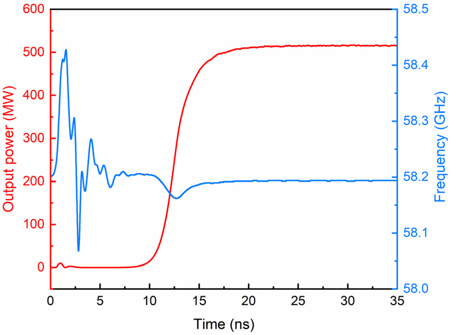
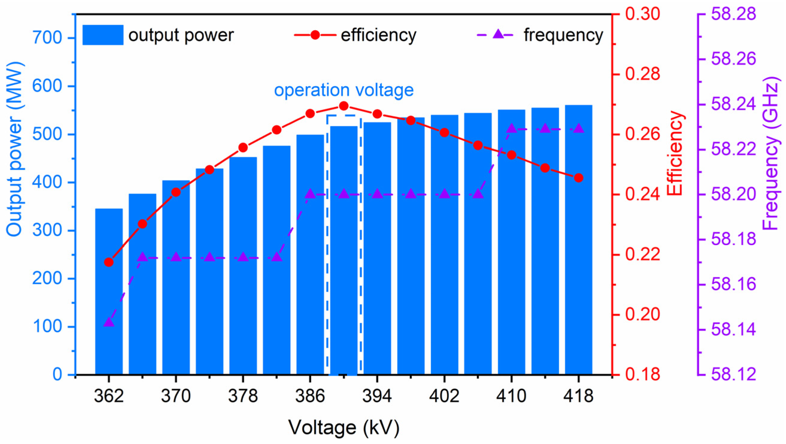
4. Typical Simulation Results

Based on the preceding analysis, the compact V-band RCTTO with reflective modulation cavity shown in Figure 13 is studied by CHIPIC 2.0.03, considering the ohmic loss due to oxygen-free copper as the conductor material. With a diode voltage of 391 kV, beam current of 4.91 kA, and guiding magnetic field of 0.6 T, the output microwave saturates at approximately 15 ns, with a stable frequency at 58.19 GHz, as shown in Figure 14. The output power is 518 MW, corresponding to a conversion efficiency of 27.0%. In comparison with the original device, the compact V-band RCTTO has three significant features: (1) the reflective modulation cavity combines the reflection and modulation function in one cavity in the RCTTO to achieve a simplified or compact structure. This allows for a substantial reduction in the axial length of the RCTTO, consequently reducing the weight and volume of the magnet system beneficial for the applications of HPM devices. Currently, most O-type HPM devices adopt separately designed reflectors and modulators, which results in the extension of the axial length of the device due to the reflector with a followed drift tube. However, in this design the distance from the input channel to the drift cavity is greatly reduced due to the removal of the reflector (as seen in Figure 4b), and the axial length of the uniform zone of the guiding magnetic field required for the device is reduced by 24.2%. (2) The output power has been increased by 24.8%, and the conversion efficiency is improved by 5.4%, which proves that the reflective modulation cavity can improve the working condition of RCTTO and can be applied to low magnetic field RCTTOs. (3) The output microwave frequency is lower than the 58.69 GHz of the original device, which is consistent with the previous analyses that the application of the reflective modulation cavity reduces the operation frequency of the device.
The distributions of the fundamental harmonic current modulation coefficient of the two devices are illustrated in Figure 15. The maximum fundamental harmonic current modulation coefficient of the compact RCTTO is 1.26, higher than that of the original device (1.19), proving that the reflective modulation cavity has a stronger modulation capability, which leads to the improvement in output power and efficiency. Furthermore, as shown in Figure 16, the axial momentum of the electron beam within the reflective modulation cavity disperses more than that within the uniform modulation cavity, indicating a greater velocity modulation depth.
Notably, Figure 17 shows the microwave output when the voltage is varied within the range of 362 kV to 418 kV at the same guiding magnetic field (0.6 T). The microwave frequency and output power gradually increase with the voltage, while efficiency rises to peak values but then declines as the voltage deviates from the optimum operating voltage. When the voltage varies from 374 kV to 418 kV, the device can maintain efficiency above 24%, indicating that the device has a wide range of operation voltages.

5. Conclusions

In order to improve the compactness of RCTTOs, a novel reflective modulation cavity that combines the functions of reflector and modulation cavity is proposed and investigated.
Cold cavity analyses and PIC simulations indicate that the reflectivity of the TEM mode of this reflective modulation cavity is close to 100% near the operation frequency. Moreover, the reflective modulation cavity has a higher gap voltage and fundamental harmonic current than the traditional uniform modulation cavity, which indicates a superior modulation capability. The main challenge in this work is to find the key structural component to efficiently optimize the reflection coefficient and modulation capacity of the reflective modulation cavity simultaneously. It has been found that the first gap of the modulation cavity can effectively improve its reflection coefficient and enhance modulation capability.
With a diode voltage of 391 kV, beam current of 4.91 kA, and guiding magnetic field of 0.6 T, the output microwave power of the compact V-band RCTTO with a reflective modulation cavity is 518 MW (conversion efficiency of 27.0%). The output microwave saturates at approximately 15 ns and the microwave frequency is stable at 58.19 GHz. Compared with the original device, the compact V-band RCTTO is characterized by 24.8% higher output power, 5.4% higher efficiency, and 24.2% shorter axial length of the uniform region of the magnetic field.
The compact V-band RCTTO has also shown a wide range of diode voltages (374–418 kV), promising stable operation with voltage fluctuations in experiments. In addition, the reflective modulation cavity can be applied to other high-frequency O-type HPM devices to increase compactness, which reduces the requirements for the region of magnetic fields, benefiting the HPM source with permanent packaging in the future.

Author Contributions

Conceptualization, Z.C., J.L. and J.H.; data curation, Z.C.; formal analysis, Z.C.; funding acquisition, L.W., J.H. and J.Y.; investigation, Z.C., J.L. and L.S.; methodology, Z.C., L.W., J.L., L.S. and J.H.; project administration, J.L. and L.S.; resources, Z.C. and J.H.; software, Z.C. and J.L.; supervision, Z.C. and J.H.; validation, L.W. and J.H.; visualization, L.W.; writing—original draft, Z.C., L.W. and W.X.; writing—review and editing, Z.C. and L.W. All authors have read and agreed to the published version of the manuscript.

Funding

This work was supported by the National Natural Science Foundation of China (No. 12205369) and the Third High-level Innovative Talent Cultivation Plan of National University of Defense Technology-Young Talents.

Data Availability Statement

The data presented in this study are available in this article.

Conflicts of Interest

The authors declare no conflicts of interest.

References

  1. Rostov, V.V.; Totmeninov, E.M.; Tsygankov, R.V.; Kurkan, I.K.; Kovalchuk, O.B.; Elchaninov, A.A.; Stepchenko, A.S.; Gunin, A.V.; Konev, V.Y.; Yushchenko, A.Y.; et al. Two-wave ka-band nanosecond relativistic Cherenkov oscillator. IEEE Trans. Electron. Devices 2018, 65, 3019–3025. [Google Scholar] [CrossRef]
  2. Zhang, D.; Zhang, J.; Zhong, H.; Jin, Z. Analysis of the mode composition of an X-band overmoded O-type Cerenkov high-power microwave oscillator. Phys. Plasmas 2012, 19, 103102. [Google Scholar] [CrossRef]
  3. Teng, Y.; Cao, Y.; Song, Z.; Ye, H.; Shi, Y.; Chen, C.; Sun, J. A ka-band TM02 mode relativistic backward wave oscillator with cascaded resonators. Phys. Plasmas 2014, 21, 123108. [Google Scholar] [CrossRef]
  4. Bai, Z.; Zhang, J.; Zhong, H. A dual-mode operation overmoded coaxial millimeter-wave generator with high power capacity and pure transverse electric and magnetic mode output. Phys. Plasmas 2016, 23, 043109. [Google Scholar] [CrossRef]
  5. Agafonov, M.A.; Arzhannikov, A.V.; Ginzburg, N.S.; Ivanenko, V.G.; Kalinin, P.V.; Kuznetsov, S.A.; Peskov, N.Y.; Sinitsky, S.L. Generation of hundred joules pulses at 4-mm wavelength by FEM with sheet electron beam. IEEE Trans. Plasma Sci. 1998, 26, 531–535. [Google Scholar] [CrossRef]
  6. Ye, H.; Chen, C.; Ning, H.; Tan, W.; Teng, Y.; Shi, Y.; Wu, P.; Song, Z.; Cao, Y.; Du, Z. Preliminary research on overmoded high-power millimeter-wave Cerenkov generator with dual-cavity reflector in low guiding magnetic field. Phys. Plasmas 2015, 22, 123110. [Google Scholar] [CrossRef]
  7. Chen, S.; Zhang, J.; Zhang, J.; Gao, J.; Zhang, P.; Ge, X. Experimental Research of the V-Band High Power Microwave Generation With Coaxial Cerenkov Oscillator. IEEE Electron. Device Lett. 2022, 43, 288–291. [Google Scholar] [CrossRef]
  8. Chen, S.; Zhang, J.; Zhang, J.; Wang, H. A V-Band Overmoded Coaxial Millimeter-Wave Oscillator Based on a New Method of Asymmetric Modes Suppression. IEEE Trans. Electron. Devices 2020, 67, 2573–2579. [Google Scholar] [CrossRef]
  9. Yang, F.; Dang, F.; Ge, X.; He, J.; Ju, J.; Zhang, X. A compact coaxial relativistic klystron amplifier with three cascaded single-gap bunching cavities for efficient output. Phys. Plasmas 2022, 29, 093111. [Google Scholar] [CrossRef]
  10. Zhang, P.; Ge, X.; Dang, F.; Chi, H.; Yang, H.; He, J. Research on sub-microsecond compact L-band relativistic Cherenkov oscillator. IEEE Trans. Electron. Devices 2022, 69, 6352–6357. [Google Scholar] [CrossRef]
  11. Lyu, Z.; Luo, H.; Wang, X.; Jiang, S.; Jin, D.; Gong, Y.; Chen, M.; Duan, Z. Compact reversed Cherenkov radiation oscillator with high efficiency. Appl. Phys. Lett. 2022, 120, 053501. [Google Scholar] [CrossRef]
  12. Zhang, W.; Ju, J.; Zhang, J.; Zhou, Y.; Zhong, H. Theoretical research on TEM mode feedback for compact design of an X-band triaxial klystron amplifier. Phys. Plasmas 2019, 26, 053102. [Google Scholar]
  13. Deng, B.; He, J.; Ling, J.; Song, L.; Wang, L. Preliminary research of a V-band coaxial relativistic transit-time oscillator with traveling wave output structure. Phys. Plasmas 2021, 28, 103103. [Google Scholar] [CrossRef]
  14. Miller, R.B. An Introduction to the Physics of Intense Charged Particle Beams; Springer: Berlin/Heidelberg, Germany, 1984; pp. 306–308. [Google Scholar]
  15. Zhou, J.; Liu, D.; Liao, C.; Li, Z. CHIPIC: An Efficient Code for Electromagnetic PIC Modeling and Simulation. IEEE Trans. Plasma Sci. 2009, 37, 2002–2011. [Google Scholar] [CrossRef]
  16. Livreri, P. Design of a High-Efficiency Ka-Band TWT Power Amplifier for Radar Applications. IEEE Trans. Plasma Sci. 2022, 50, 2824–2829. [Google Scholar] [CrossRef]
  17. Iihara, T.; Ito, Y.; Fukuoka, K.; Suehiro, K.; Maki, K. Enhancing the Properties of Oxygen-Free Copper for High-Current Applications through Trace Element Additions. Mater. Trans. 2024, 65, 434–439. [Google Scholar] [CrossRef]
  18. de Jong, M.S.; Adams, F.P.; Hutcheon, R. Computation of RF Fields for Applicator Design. J. Microw. Power Electromagn. Energy 1992, 27, 136. [Google Scholar] [CrossRef]
  19. Vlasov, A.N.; Shkvarunets, A.G.; Rodgers, J.C.; Carmel, Y.; Antonsen, T.M.; Abuelfadl, T.M.; Lingze, D.; Cherepenin, V.A.; Nusinovich, G.S.; Botton, M.; et al. Overmoded GW-class surface-wave microwave oscillator. IEEE Trans. Plasma Sci. 2000, 28, 550–560. [Google Scholar]
  20. Xiao, R.; Chen, K.; Shi, Y.; Chen, C. Toward 80% Efficiency in a Super Klystron-Like Relativistic Backward Wave Oscillator with Second and Third Harmonic Coaxial-Premodulation Cavity. IEEE Trans. Electron. Devices 2023, 70, 2521–2525. [Google Scholar] [CrossRef]
  21. Lemke, R.W.; Clark, M.C.; Marder, B.M. Theoretical and experimental investigation of a method for increasing the output power of a microwave tube based on the split-cavity oscillator. J. Appl. Phys. 1994, 75, 5423–5432. [Google Scholar] [CrossRef]
  22. Xiao, R.; Chen, C.; Wu, P.; Song, Z.; Sun, J. Role of dc space charge field in the optimization of microwave conversion efficiency from a modulated intense relativistic electron beam. J. Appl. Phys. 2013, 114, 214503. [Google Scholar] [CrossRef]
  23. Xiao, R.; Chen, K.; Wang, H.; Wang, D.; Shi, Y.; Gao, L. Theoretical calculation and particle-in-cell simulation of a multi-mode relativistic backward wave oscillator operating at low magnetic field. Phys. Plasmas 2022, 29, 043103. [Google Scholar] [CrossRef]
Figure 1. Schematic of an original V-band RCTTO.
Electronics 13 03290 g001
Figure 2. Temporal output of power and frequency of the original V-band RCTTO.
Electronics 13 03290 g002
Figure 3. Axial distribution of backward power flux.
Electronics 13 03290 g003
Figure 4. (a) Equivalent model of the modulation cavity and (b) geometric structure between coaxial input channel and drift cavity for both uniform and reflective modulation cavity.
Electronics 13 03290 g004
Figure 5. Reflection coefficient for TEM mode of (a) different first gaps and (b) reflective modulation cavity.
Electronics 13 03290 g005
Figure 6. Distribution of the |E| field at the operation frequency when injecting a TEM mode from the right port of (a) uniform modulation cavity and (b) reflective modulation cavity.
Electronics 13 03290 g006
Figure 7. Leakage power from the left port when injecting a TEM mode from the right port.
Electronics 13 03290 g007
Figure 8. The normalized Ez distribution at the operation frequency of different modulation cavities.
Electronics 13 03290 g008
Figure 9. Different longitudinal modes in the reflective modulation cavity.
Electronics 13 03290 g009
Figure 10. The Q-factor of the uniform modulation cavity and reflective modulation cavity.
Electronics 13 03290 g010
Figure 11. Gap voltage of the uniform modulation cavity and reflective modulation cavity.
Electronics 13 03290 g011
Figure 12. Fundamental harmonic current distribution when injecting a TEM mode from the right port.
Electronics 13 03290 g012
Figure 13. Schematic of the compact V-band RCTTO.
Electronics 13 03290 g013
Figure 14. Temporal output of power and frequency of the compact low magnetic field V-band RCTTO.
Electronics 13 03290 g014
Figure 15. Fundamental harmonic current modulation coefficient.
Electronics 13 03290 g015
Figure 16. Phase space plot of axial momentum.
Electronics 13 03290 g016
Figure 17. Output power, efficiency, and frequency versus voltage.
Electronics 13 03290 g017
Disclaimer/Publisher’s Note: The statements, opinions and data contained in all publications are solely those of the individual author(s) and contributor(s) and not of MDPI and/or the editor(s). MDPI and/or the editor(s) disclaim responsibility for any injury to people or property resulting from any ideas, methods, instructions or products referred to in the content.

