Article

Frequency Support Coordinated Control Strategy of Renewable Distributed Energy Resource Based on Digital Twins

1
State Grid Shanxi Electric Power Company Electric Power Research Institute, Taiyuan 730087, China
2
College of Electrical Engineering, Shanghai University of Electric Power, Shanghai 200090, China
*
Author to whom correspondence should be addressed.
Electronics 2024, 13(17), 3403; https://doi.org/10.3390/electronics13173403
Submission received: 8 July 2024 / Revised: 6 August 2024 / Accepted: 23 August 2024 / Published: 27 August 2024
(This article belongs to the Special Issue Power-Electronic-Based Smart Grid and Its Control Technology)

Abstract

:
The integration of high-penetration renewable energy sources is playing an increasingly important role in the frequency regulation of the power system. However, due to the varying output characteristics and response speeds of different renewable distributed energy resources (DERs), the overall response from the collective output of these distributed energy resources may not meet expected requirements and could have adverse effects on the grid. One drawback of traditional distributed coordinated control is its high communication requirements. This paper proposes using digital twin (DT) technology for the coordinated control of distributed energy resources, which can minimize the communication needs between various distributed energy resources while achieving coordinated control. Verification of the frequency support coordinated control strategy based on digital twin technology shows that it can effectively enhance the individual output characteristics and overall response of each distributed energy resource, providing effective support for grid frequency.

1. Introduction

With various decarbonization targets set around the world, the power system has become a major area for low-carbon transformation. Renewable distributed energy resources, represented by wind and solar power, have continued to grow rapidly in the power grid due to their economic and geographical characteristics and have become the main driving force for the development of the global new energy sector [1,2,3].
However, the large-scale integration of renewable DERs into the power system [4,5] poses adverse effects on the coordination of supply and demand balance and on the reliability of power supply. This is especially true in distribution networks that incorporate many power electronic devices, which significantly impact the inertia and stability of the distribution network, leading to a decline in power quality. For example, during sudden power imbalance events in the grid, the inherent randomness, intermittency, and high volatility of renewable energy generation increase the difficulty of maintaining active power balance and reduce system stability. This can cause renewable energy power electronic devices to easily disconnect during frequency disturbances, negatively affecting system frequency stability. On 28 September 2016, extreme weather conditions led to a large-scale disconnection of wind power units in the South Australia grid, where renewable energy penetration was high, causing the system frequency to drop below 47 Hz and taking more than 50 h for full power supply restoration [6]. On 9 August 2019, a lightning strike caused a chain of events, including distributed energy exit and frequency protection actions, leading to a major blackout in the UK, resulting in power outages in several major cities and significant load losses [7].
Although the integration of numerous renewable DERs presents operational challenges to the grid, effective control of renewable energy sources—given their controllability and considerable capacity—can bring many benefits to the power system, such as providing voltage support, frequency support, improving power quality, reducing power supply losses, and enhancing reliability. This is particularly evident in the role of renewable DERs in power system frequency control [8,9]. Reference [10] proposes an emergency frequency control optimization model for the safety of the sending-end grid under DC blocking, which involves coordinated control of renewable DERs and conventional units to meet frequency requirements with minimal system control costs, although it does not account for the uncertainties in the output of renewable DERs. Reference [11] suggests a hierarchical coordinated control strategy for the active power of large-scale clustered renewable energy, optimizing active control targets layer by layer to ensure the safety, economy, and fairness of the controlled system. Reference [12] aims to minimize costs by proposing a coordinated control strategy for wind power storage systems and synchronous units, reducing the overall frequency regulation cost and the load of each wind farm while meeting frequency regulation needs. Reference [13] introduces a hierarchical control strategy for active power composed of wind power and energy storage systems, reducing wind turbine operating costs; however, due to the high construction costs of energy storage systems, large-scale application in the grid is currently not feasible. Traditional coordinated control methods have not considered the increased communication issues associated with the coordinated control of renewable DERs, where excessive communication channels can adversely affect the overall output of renewable DERs.
Digital twin technology plays a key role in Industry 4.0 [14,15], and in the power system, digital twin technology is more specifically defined as “a software-based abstraction that connects complex physical system through continuous data streams, which can reflect the operation statues of physical system simultaneously” [16], as shown in Figure 1. There are three main methods for creating digital twin models: physics-based modeling [17], data-driven modeling [18], and physics-data hybrid modeling [19]. In recent years, digital twin technology has gradually been applied in the power system field, mostly for grid fault diagnosis and online analysis [20,21,22].
The DERs under the proposed coordinated control should belong to the same/allied operator aiming to actively support local network frequency, which may be a microgrid, renewable aggregator, or virtual power plant. Besides, the proposed method focuses on DERs within the same/allied operator in the local network and only considers the support for the local network. It is worth mentioning that the proposed method can solve the challenges of communications. For the traditional distributed coordinated control method, mutual communication among DERs often faces problems such as a complex and massive number of communication channels, asynchronous signals, etc. [23], making it difficult to achieve communication among DERs. While the proposed coordinated control strategy is based on digital twins, which only require communication between each DER and the server where DTs of DERs and distributed coordinated control are built. In this way, the communication burden can be significantly reduced.
For renewable integration protocols, according to several standards and guides, such as Chinese National Standard GB/T19963-2021 [24], IEC62116-2014 [25], and Cigre Benchmark Systems for Network Integration of Renewable and Distributed Energy Resources [26], which all indicate the technical integrating requirements for DERs. According to EN50549-1:2019 [27] from Europe and Grid Code OC6 [28] from the UK, DERs should have the ability to respond quickly after frequency events occur, with a response time of less than 5–10 s to meet the requirements of DER supporting the grid. The method proposed in this article can meet this response requirement. In addition, the proposed method can be potentially straightforward to implement in the field, which can improve the response time of traditional distributed control without changing the control structures. For example, if traditional droop control can work (which is already widely used in the field), then the method proposed in this article can be directly applied. While meeting the requirements of the above grid standards, the proposed method can significantly reduce the response time of DER frequency support, which is one of the main motivations for proposing this method and of great significance.
In the Section 2, this paper introduces the principles of optimizing the coordinated control of renewable DER output characteristics and the advantages of distributed coordinated control. The Section 3 describes the modeling method of the digital twin for renewable DERs, and the design of distributed renewable energy coordinated control based on the digital twin. The Section 4 tests the accuracy of the digital twin models and demonstrates the effectiveness of the proposed method for frequency support through case analysis. Finally, the conclusion of this paper is given in the Section 5.

2. Coordinated Control Method for Renewable Energy Generation

In this section, the topology of inverter-based renewable energy sources is first introduced. Then, the coordinated control method used in this paper is presented. After that, the disadvantages of the centralized control method are compared, and the distributed control method is chosen to coordinate the various renewable energy sources.

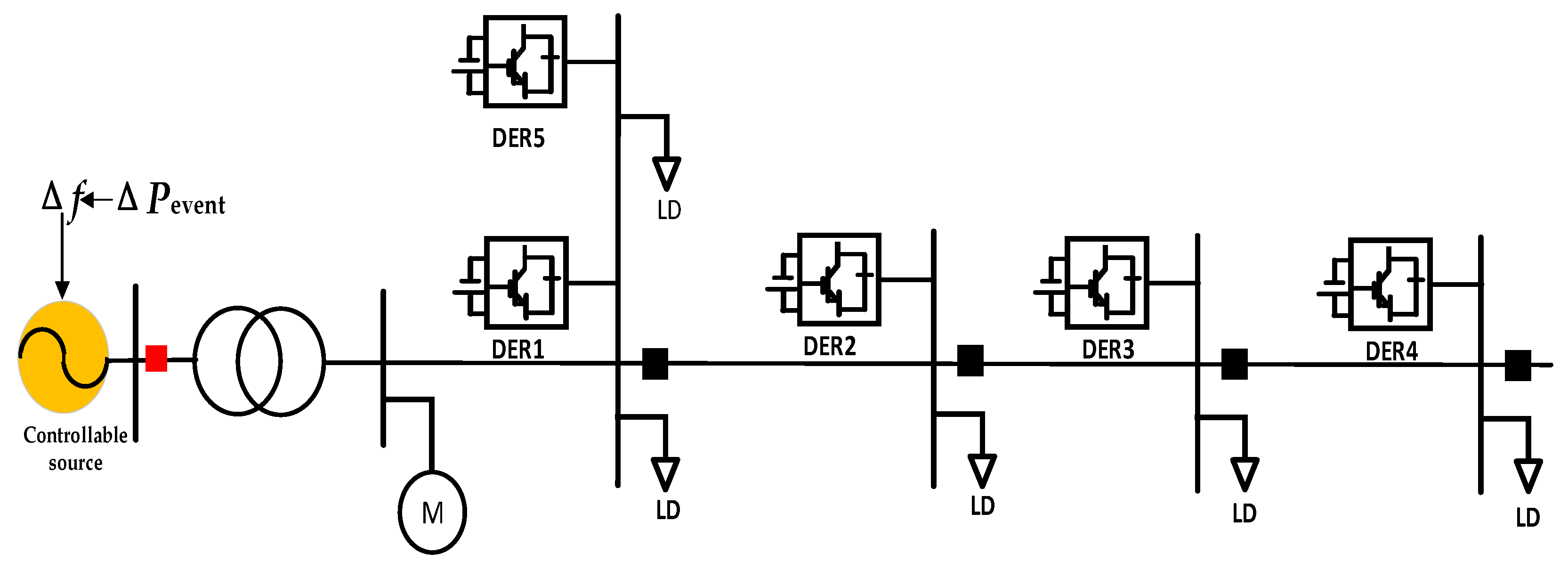
2.1. Topology of Inverter-Based Renewable Energy Sources

The grid-connected operation of inverter-based renewable energy generation units consists of three parts: the renewable energy source, the converter, and the power grid. The type of renewable energy source is determined by the specific type of renewable energy, mainly including solar power devices, wind power devices, energy storage devices, gas turbines, etc. Taking photovoltaic power generation as an example, the direct current (DC) power source is composed of photovoltaic panels and a DC boost circuit. In a specific working environment, the output power of the inverter can be regulated by adjusting the DC capacitor voltage. For energy storage systems, the battery pack serves as the DC source. Figure 2 shows the grid-connected topology of an inverter-based renewable energy generation unit based on a three-phase LC filter. As shown in the figure, the renewable energy source is connected to the converter through a DC capacitor.
As the power system continues to develop, renewable energy inverter technology has the following three control methods: active and reactive power control (PQ control), voltage and frequency control (V&F control), and droop control [29]. Currently, the most commonly used method for connecting renewable energy sources to the grid is PQ control. Based on the given active and reactive power, the renewable energy plant outputs the specified active and reactive power. Therefore, this paper uses PQ control as the control strategy for renewable energy inverters. After voltage stabilization by a capacitor, the renewable energy source is converted through the inverter and connected to the grid point via LC filtering. Lf and Cf represent the inductor and capacitor of the filter, respectively; Rg and Lg are the equivalent resistance and inductance of the line, respectively; ea, eb, and ec represent the three-phase voltages on the AC output side of the inverter, ia, ib, and ic represent the three-phase currents on the AC output side of the inverter; va, vb, and vc are the three-phase voltages at the grid connection point; and vg is the grid voltage value. The inverter control system will use the measured information of the three-phase voltage vabc at the PCC bus and the three-phase voltage vg on the grid side, along with the set values of active power Pref and reactive power Qref, to determine the current reference values based on the PQ control strategy. It uses PI control to regulate the three-phase current, iabc. Finally, it converts this into pulse signals s1~s6 for the PWM modulation module, achieving the specified control objectives.

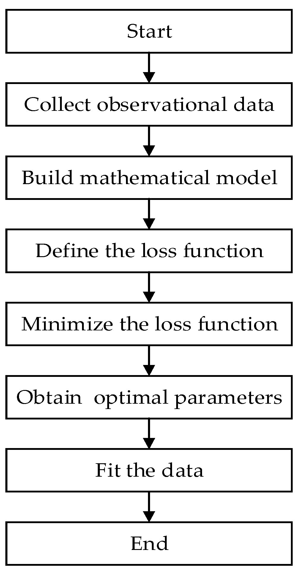
2.2. Least Squares Approximation

We assumed a certain distribution network with K controllable renewable DERs. These K renewable DERs collectively provide power output to this distribution network. Given an active power disturbance in this network, the K renewable DER needs to output active power according to the system’s required active power reference values, which can be expressed as:
P M 0 = i = 1 k P iref 0 ,
P ML = i = 1 k P iML ,
where Piref0 is the initial active power reference value of the ith renewable DERs, PM0 is the initial requested active power output of all DERs to the distribution network, PiML is the actual active power output value of the ith DER, and PML is the aggregated actual active power output of all DERs. If various DERs are not subject to coordinated control, each DER will default to outputting active power reference values to the grid according to the conventional PQ control method. However, Section 4 will demonstrate that due to the significant differences in the output characteristics of each DER, their aggregated response may not meet the expected requirements.
Least squares approximation, as a commonly used optimization method in multi-input, multi-output systems, is based on the idea of adjusting model parameters to minimize the sum of squares of residuals between model predictions and observed data, thereby finding the optimal solution. Its simple flowchart is shown in Figure 3. In the field of renewable energy coordination control, least squares approximation can adjust the input signals of DERs to make their output characteristics closer to the desired values. This paper takes the minimization of the sum of squares of residuals between the expected output and actual output of DERs as the optimization objective:
min P P M 0 P ML 2 ,
where the optimization input variable P represents the input reference values of each DER:
P = [ P 1 ref , P 2 ref , , P kref ] ,
The optimization problem of the least squares approximation is commonly solved using the gradient descent method. Given the initial active power reference value P0, we calculated the gradient of the optimization objective function with respect to the input signal P. Here, the active power reference value P0 is represented as:
P 0 = [ P 1 ref 0 , P 2 ref 0 , , P kref 0 ] ,
The gradient of the objective function with respect to the input signal P is expressed as:
P P M P ML 2 ,
According to the update rule of the gradient descent method, we updated the current input signal to reduce the value of the optimization objective function. The update rule can be expressed as:
P iref ( t + 1 ) = P iref ( t ) α P iref P M 0 P ML 2 ,
where α is the learning rate used to control the step size of each update, typically set as α = 0.2.
This coordination control method is complementary to the output characteristics of each DER, ensuring the optimization of the output characteristics of each DER and improving the aggregated output response.

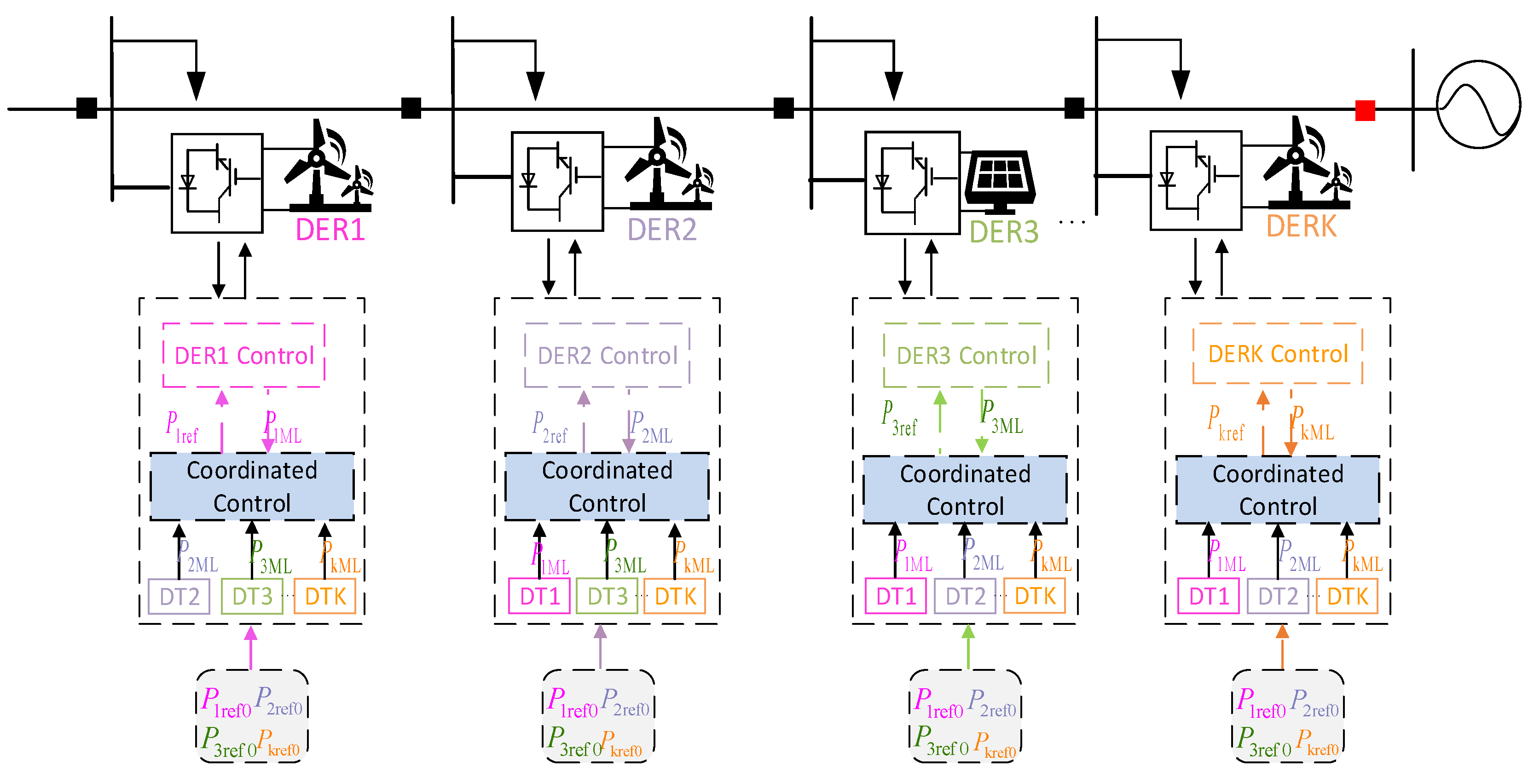
2.3. Distributed Coordinated Control Method

The coordination control proposed in Section 2.1 can typically be implemented through two traditional methods: centralized and distributed methods. The centralized control method is a control strategy that consolidates all control decisions and computational tasks within a single central control unit. When traditional centralized control methods are used in the coordinated control of renewable energy sources, coordination control is assumed to be implemented at the active power allocation point, as shown in Figure 4. Coordination control requires obtaining actual active power from each DER and issuing optimized active power input values to each DER. It can be seen that with centralized methods, bidirectional real-time communication is required between each DER and the coordination controller. If there are K DERs participating in coordination control, at least 2K communication channels are needed. As the system scales up, the computational load of centralized coordination control increases, and computing speed may be affected. Additionally, centralized control, because all control decisions go through a single point for coordination and execution, can lead to system-wide impacts or even system collapse if that point fails or malfunctions. Therefore, distributed methods are often used to replace centralized methods.
With the growing global energy demand and pressure for environmental protection, traditional centralized control systems for renewable energy are struggling to meet the needs of modern power systems. Distributed control, as an emerging technology, achieves efficient management and optimized scheduling of power systems through the collaborative work of distributed nodes. The concept of distributed control originated from the development of distributed computing and control theories and has matured alongside advancements in information technology and communication. In the field of power energy, distributed control systems, through the collaborative work of multiple autonomous control units, effectively address the complexity and dynamics of energy systems.
As shown in Figure 5, to replace the coordination controller in the centralized method, each participating DER in the coordination control will be equipped with its own coordination controller. Therefore, K renewable DER will have K coordination controllers. When using the distributed method, each DER receives an initial active power reference value, and each DER needs to engage in bidirectional communication with the other K-1 DERs to exchange actual output power as indicated in red in Figure 5. This means that K renewable DERs require a total of K2 communication channels. Although using the distributed method may increase the system’s communication requirements, it avoids the single point of failure of the coordination controller in centralized control, which could lead to the failure of the entire system. This method improves the system’s fault tolerance and security.

3. Coordinated Control of DERs Based on Digital Twins

In Section 2, the coordinated control strategy used in this paper is introduced, and two control methods for renewable DERs are compared, namely, the centralized method and the distributed method. However, traditional coordination control methods often have a high demand for communication. The increase in communication channels can lead to significant communication delays, which may seriously affect the overall output response time and characteristics of each DER. Therefore, this paper proposes using the digital twin model of DERs to predict the actual output power of each participating DER in coordinated control, thereby minimizing the real-time communication requirements of the coordination control strategy.

3.1. Distributed Coordinated Control Based on Digital Twins

The design and implementation of the distributed coordination control scheme using the digital twin model of renewable DERs are shown in Figure 6. In contrast to the traditional distributed approach, where communication is needed between each DER to exchange power information, this method involves K renewable DERs in the control. Each DER is equipped with a coordination controller and the digital twin model of the remaining (K − 1) DERs. For the ith renewable DER, coordination control is achieved by exchanging power information with the other (K − 1) digital twin models placed within the DER. This approach only requires sending the initial reference power to each DER without the need for real-time communication with other renewable DERs. The communication lines are reduced from K2 to K, eliminating real-time communication among all DERs and significantly reducing the dependency of the coordination control strategy on real-time communication.

3.2. Digital Twin Modeling of DERs

As described in Section 1, there are generally three methods for establishing a digital twin model: physics-based, data-driven, or a combination of physics and data. For the physics-based modeling method, a detailed understanding of the internal parameters and control methods of the renewable DERs is required, making it difficult to implement in the real world due to the challenge of obtaining various information parameters. Therefore, in this paper, a data-driven approach is used, where the dynamic response of the active power output of each DER is collected to generate the digital twin model of each DER. The specific process is illustrated in Figure 7.
The first step in establishing the digital twin model of a renewable DER is to apply an active power reference signal to the target DER. This signal can be a simple step response or a more complex signal. The signal can be applied to an actual DER or an accurate model of a renewable DER, which can be treated as a black-box model without detailed internal information. The active power reference signal and the output signal response of the renewable DER are recorded and saved in a time-series data format. These data are then imported into system identification tools, as shown in Stage I of Figure 6. To improve system identification and ensure that the obtained system model is accurate and meets expectations, it is necessary to determine the number of poles and zeros in the transfer function. After generating the transfer function, it can be tested using the same active power reference signal as before, and the response output by the transfer function can be compared with the actual active power output response collected in Stage I. The processes in Stages I and II can be automated until the accuracy of the digital twin model meets the expected standards.
Once the accuracy of the model meets the expected requirements, the digital twin model can be built on a platform and connected to real-time data interfaces. This allows the digital twin model to be updated in real-time, reflecting the input-output characteristics of the actual DER.

4. Simulation and Case Study

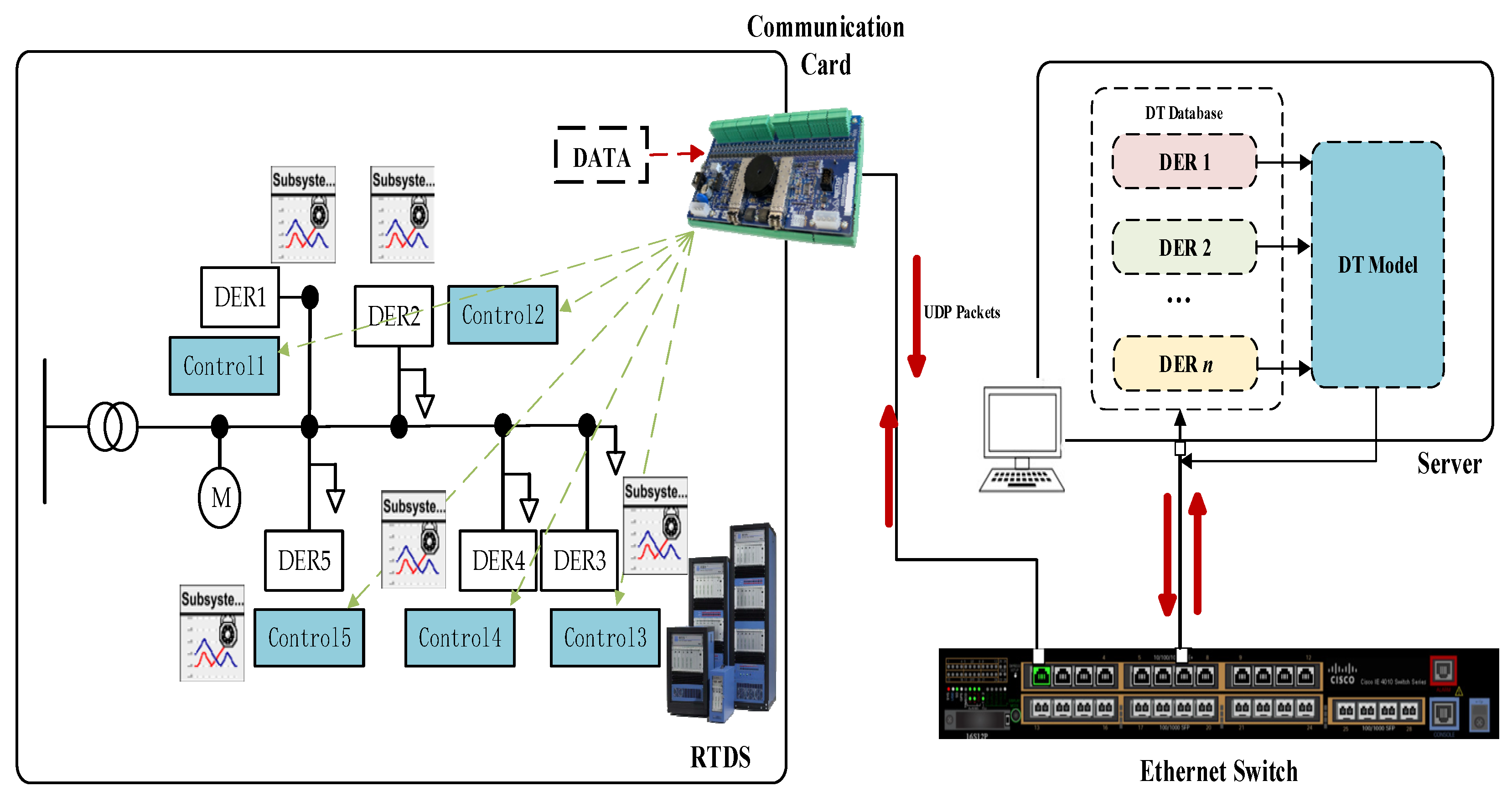
4.1. Digital Twin Testing Platforms

To simulate the actual operating conditions of the distribution network and verify the accuracy of the digital twin model established in this paper, a hardware-in-the-loop (HIL) simulation method was used. The distribution network model was constructed in RTDS using RSCAD_5.014.1 software to simulate the operation of the actual physical distribution network. Real-time simulation in RTDS communicates with the server via an Ethernet switch, exchanging information using the UDP protocol. Various measurement modules in RTDS measure the distribution network data, which is output from RTDS via communication boards, transmitted through the Ethernet switch, and then input to the server. The digital twin model of the renewable DER is established on the server side and fed back to the distributed control locations. The digital twin testing platform is shown in Figure 8.

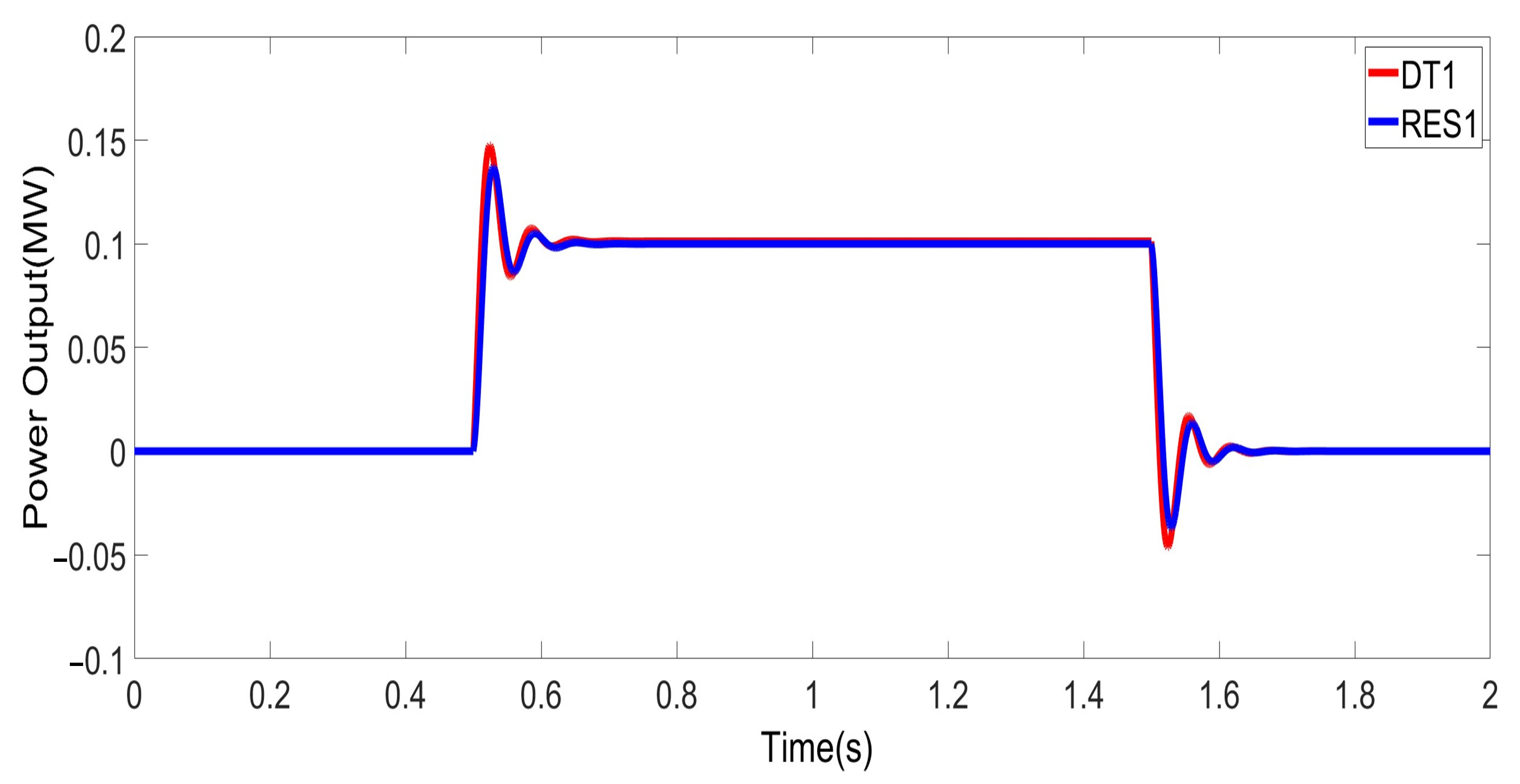
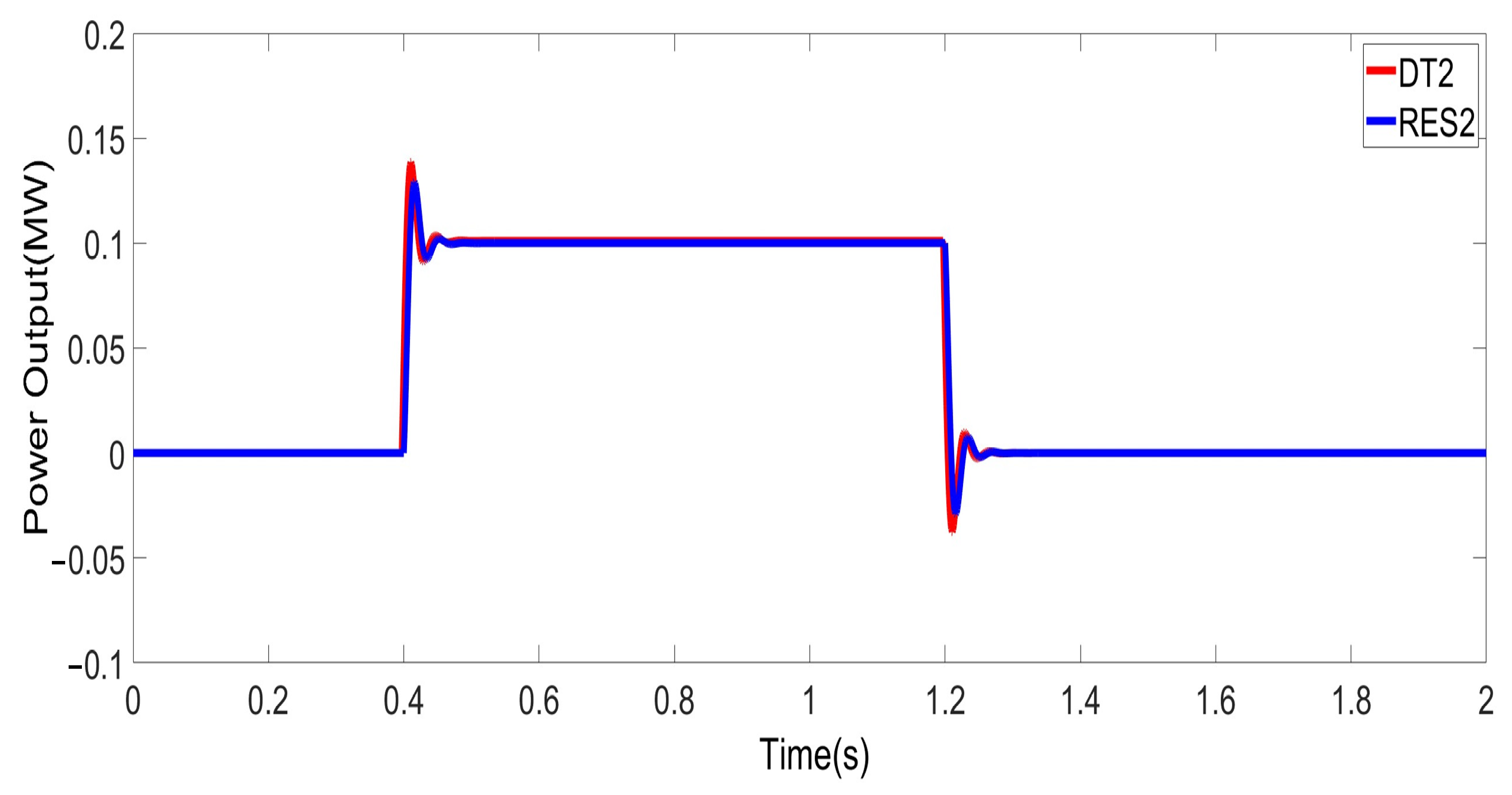
4.2. Accuracy Testing of Digital Twin Models

The digital twin modeling of the DER model is carried out according to the digital twin model flowchart in Figure 6. After the digital twin model is established, compare the actual output characteristics of the DER with the output characteristics of the digital twin model to test its accuracy. We assumed there are three renewable DERs. For DER1, we applied a rising step signal at 0.5 s and a falling step signal at 1.5 s. For DER2, we applied a rising step signal at 0.4 s and a falling step signal at 1.2 s. For DER3, we applied a rising step signal at 0.8 s and a falling step signal at 1.4 s. Figure 9 shows the comparison between the actual output characteristics and the digital twin output characteristics of DER1; Figure 10 shows the comparison between the actual output characteristics and the digital twin output characteristics of DER2; and Figure 11 shows the comparison between the actual output characteristics and the digital twin output characteristics of DER3.
It can be seen that when a step response signal is applied to the active power reference value of the renewable DERs, the digital twin model’s active power output of each DER can follow the actual output of the DER well, accurately reflecting the dynamic characteristics of each DER.

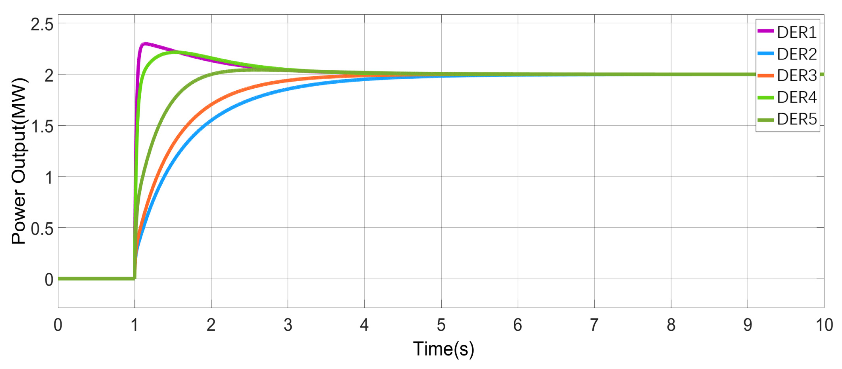
4.3. Verification of Frequency Support Effectiveness

The distribution network model used in the experiment is shown in Figure 12. This grid consists of controllable power sources, transformers, electric motors, loads, and renewable DERs. Among them, the DERs are controlled using traditional PQ control methods. The generator model adopts active power droop control to simulate the traditional generator’s frequency droop characteristic curve and maintain frequency stability. The droop control formula is as follows:
f = f n m ( P n P ) ,
where f and fn are the frequency value and rated frequency, respectively; Pn is the active power required by the grid, and P is the actual active power output of the generator; m is the active power control coefficient, and in this experiment, m is taken as 0.03. In this case, the relationship between the total output active power and the voltage of the network is shown in Figure 13.
In this test network, the initial load of the system is set to 1 GW, and during normal operation, the rated output power of the power source is also 1 GW. At this time, the grid has active power balance, and the grid frequency is at its rated value of 50 Hz. Additionally, five renewable DERs are simulated in the network, with an output of 0 when the grid is in power balance.
Since the grid power source is controllable, frequency events such as frequency decreases can be simulated by changing the power imbalance value (ΔPevent) in the grid power source model. According to GB/T 15945-2008 [30], the frequency limit should be maintained between 49.8 Hz and 50.2 Hz, and when the capacity is small, the deviation limit can be relaxed to 49.5 Hz and 50.5 Hz. Therefore, a DER aggregator is used to monitor the frequency. When the frequency drops below 49.8 Hz, the frequency support characteristics of the renewable DERs will be triggered.
We simulated a loss of 10 MW generation. According to Equation (8), the grid frequency at this time drops to 49.7 Hz. During the frequency drop process, due to system inertia, the frequency often experiences significant oscillations. We designed the following three scenarios to verify the effectiveness of the digital twin-based coordinated control strategy for frequency support: (1) The grid relies solely on conventional primary frequency response without the support of renewable DERs. (2) The renewable DERs support the grid based on their inherent control without coordinated control. (3) The renewable DERs support the grid through the proposed digital twin-based coordinated control strategy. In these scenarios, the output of each DER is distributed equally.
When each DER provides frequency support but lacks coordinated control, the active power output is shown in Figure 14. At this time, due to the lack of coordinated control, the output characteristics between the DERs are poor, and the time for the output active power to reach the set value is slow, which is not conducive to the DERs supporting the grid frequency.
When coordinated control based on digital twinning is carried out among various DERs, the active power output is shown in Figure 15. Each DER performs coordinated control based on digital twinning. At this time, DER1 and DER2 can complement each other with DER3, DER4, and DER5 through overshoot, and the active output characteristics of each DER are improved to reach the set value of total active power output faster, resulting in a significant improvement in output characteristics.
The aggregated active power output of the renewable DERs in the three scenarios is shown in Figure 16. This provides a more intuitive comparison, demonstrating that the coordinated control based on the digital twin has better output characteristics and a faster output response compared to the scenario without coordinated control.
The support of the power grid by renewable DERs in various scenarios is illustrated in Figure 17.
(1) Without a DER frequency support: The grid frequency drops, and without a DER frequency support, the active power output of each DER is 0. At this time, the grid frequency fluctuation is the most severe, with the lowest frequency point being 49.3 Hz, which seriously endangers the safety of the power system.
(2) The DER does not perform coordinated control to frequency support: When the grid frequency drops, each DER does not perform coordinated control frequency support. At this time, each DER outputs active power, and the grid frequency is improved. However, due to the slow output response, the lowest grid frequency is 49.6 Hz and the highest grid frequency is 50.18 Hz. At this time, there are still significant fluctuations in the grid frequency.
(3) DER based on a DT coordinated control frequency support: When the grid frequency drops, each DER performs coordinated control frequency support based on digital twins. At this time, each DER coordinates and cooperates with each other, with the lowest grid frequency of 49.76 Hz and the highest grid frequency of 50.1 Hz. The fluctuation amplitude of the grid frequency is further reduced, and the frequency support effect is improved.
Comparing the grid frequencies in the three scenarios, it can be seen that the distributed renewable energy coordination control strategy based on the digital twin can effectively reduce the amplitude of frequency fluctuations during a grid frequency drop, improving the safety of grid operation and demonstrating good results.
Compared with the coordinated control based on digital twins in this article, traditional coordinated control has shortcomings in communication delay and requires a higher communication delay. In the event of a fault, the DER output active power reaches the set value as the support time. The required time for the two controls in different scenarios is shown in Table 1.
According to Table 1, it can be seen that the time required for fully supporting active power in coordinated control based on digital twins is lower than that required in traditional coordinated control, indicating that the method proposed in this paper has a good effect on reducing communication delay under coordinated control.

4.4. Technical Benefits

The frequency support coordinated control strategy based on digital twins proposed in this article can effectively improve the system frequency response while minimizing real-time communication requirements by coordinating the input-output characteristics between various DERs. In addition, the proposed coordinated control strategy can also be used as a reference for various grid sizes and configurations.
For utility companies, this method will bring significant technical benefits, as it improves the frequency stability of the power system while reducing the investment required for communication facilities, resulting in economic benefits. By effectively controlling each DER, there is great potential for DER to provide auxiliary services to the power grid, which will bring significant commercial benefits to the stakeholders of DER.5.

5. Conclusions

In the case of a grid frequency drop, the additional active power output from renewable DERs can support the grid frequency. However, there are issues such as poor output characteristics and slow aggregated output power response. A distributed renewable energy coordination control strategy based on digital twin technology is proposed to optimize the aggregated output response of renewable DERs, effectively supporting grid frequency regulation. The following achievements have been made:
  • A coordination control strategy for renewable DERs has been proposed, improving the output characteristics and addressing the shortcomings of differing and unexpected outputs, achieving optimized active power output.
  • For conventional centralized and distributed coordination control methods, due to the drawbacks of centralized control, such as a large system computational load and poor safety due to centralized control, a distributed method for coordination control is proposed, offering better fault tolerance for the system.
  • Digital twin technology is used to reduce the high real-time communication requirements of coordination control, reducing the communication channels for distributed coordination control from the original K2 to K and significantly decreasing communication demands.
  • The distributed renewable energy coordination control strategy based on digital twin technology is compared with the scenarios of renewable DERs without support and with support but without coordinated control, fully demonstrating the effectiveness of the proposed method for grid frequency control.

Author Contributions

Conceptualization, X.C. and J.W.; methodology, X.G., L.J. and L.J.; software, X.C. and X.G.; validation, X.C. and L.J.; formal analysis, X.C. and H.Z.; investigation, H.Z. and L.H.; resources, J.W. and L.H.; data curation, J.W., H.Z. and L.J.; writing—original draft preparation, X.C. and L.J.; writing—review and editing, J.W., X.G. and L.H.; visualization, X.C. and H.Z.; supervision, X.C. and X.G.; project administration, J.W. and L.H.; funding acquisition, X.C. and H.Z. All authors have read and agreed to the published version of the manuscript.

Funding

This work is supported by State Grid Shanxi Electric Power Company Science and Technology Project Research (52053023000V).

Data Availability Statement

The data presented in this study are available on request from the corresponding author.

Conflicts of Interest

The authors declare that the research was conducted in the absence of any commercial or financial relationships that could be construed as a potential conflict of interest.

References

  1. Jafari, M.; Korpås, M.; Botterud, A. Power System Decarbonization: Impacts of Energy Storage Duration and Interannual Renewables Variability. Renew. Energy 2020, 156, 1171–1185. [Google Scholar] [CrossRef]
  2. Zhao, Y.; Xia, S.; Zhang, J.; Hu, Y.; Wu, M. Effect of the Digital Transformation of Power System on Renewable Energy Utilization in China. IEEE Access 2021, 9, 96201–96209. [Google Scholar] [CrossRef]
  3. Fulli, G.; Masera, M.; Spisto, A.; Vitiello, S. A Change Is Coming: How Regulation and Innovation Are Reshaping the European Union’s Electricity Markets. IEEE Power Energy Mag. 2019, 17, 53–66. [Google Scholar] [CrossRef]
  4. Thompson, M.; Stark, C. Climate Change Committee. Net Zero–Technical Report; Climate Change Committee: London, UK, 2019. [Google Scholar]
  5. Stark, C.; Thompson, M.; Andrew, T.; Beasley, G.; Bellamy, O.; Budden, P.; Cole, C.; Darke, J.; Davies, E.; Feliciano, D.; et al. Net Zero: The UK’s Contribution to Stopping Global Warming; Climate Change Committee: London, UK, 2019. [Google Scholar]
  6. Hui, Z.; Feng, S.; Tie, L.I.; Qiang, Z.; Junci, T.; Tao, Z. Analysis of the “9·28” Blackout in South Australia and Its Enlightenment to China. Autom. Electr. Power Syst. 2017, 41, 1–6. [Google Scholar]
  7. Sun, H.; Xu, T.; Guo, Q.; Li, Y.; Lin, W.; Yi, J.; Li, W. Analysis on Blackout in Great Britain Power Grid on August 9th, 2019 and Its Enlightenment to Power Grid in China. Proc. CSEE 2019, 39, 6183–6192. [Google Scholar]
  8. Li, G.; Liu, X.; Xin, Y.; Jiang, T.; Yan, K.; Wang, T. A Review of Frequency Stability in Power Systems with High Proportion of Renewable Energy. High Volt. Technol. 2024, 3, 1165–1181. [Google Scholar]
  9. Wang, Z.; Zhang, X.; Yang, H.; Zhang, H. Study on Primary Frequency Control Strategies for Photovoltaic Power Plants. Power Syst. Clean Energy 2023, 39, 120–128. [Google Scholar]
  10. Zhong, Z.; Wen, Y.; Ye, X.; Liu, F.; Guo, W.; Zhou, S. Frequency Emergency Control Strategy for Sending-End Power Grid with High Proportion of Renewables and High Load Coordination of Multiple Resource Types. Power Syst. Technol. 2024, 12, 1355344. [Google Scholar]
  11. Shi, G.; Sun, R.; Xu, H.; Qiao, Y. Active Power Hierarchical Coordination Control Strategy for Large-Scale Clustered Renewable Energy. Power Syst. Technol. 2018, 42, 2160–2167. [Google Scholar]
  12. Zhao, C.; Wang, H.; Gu, Z.; Liu, X.; Zhu, G. Dispersed Wind-Storage System Frequency and Voltage Regulation Capability Evaluation Key Technologies. Compr. Smart Energy 2024, 46, 78–87. [Google Scholar]
  13. Li, J.; Wang, D.; Fan, H.; Yang, D.; Fang, R. Hierarchical Optimization Control Method for Active Distribution Networks with Mobile Energy Storage. Autom. Electr. Power Syst. 2022, 46, 189–198. [Google Scholar]
  14. Di Nardo, M. Developing a Conceptual Framework Model of Industry 4.0 for Industrial Management. Ind. Eng. Manage. Syst. 2020, 19, 551–560. [Google Scholar] [CrossRef]
  15. Bazmohammadi, N.; Madary, A.; Vasquez, J.C.; Mohammadi, H.B.; Khan, B.; Wu, Y.; Guerrero, J.M. Microgrid Digital Twins: Concepts, Applications, and Future Trends. IEEE Access 2021, 10, 2284–2302. [Google Scholar] [CrossRef]
  16. Hicks, B. Industry 4.0 and Digital Twins: Key Lessons from NASA. In The Future Factory Blog; The Future Factory: Barnet, UK, 2019. [Google Scholar]
  17. Kumar, M.; Kvamsdal, T.; Johannessen, K.A. Simple A Posteriori Error Estimators in Adaptive Isogeometric Analysis. Comput. Math. Appl. 2015, 70, 1555–1582. [Google Scholar] [CrossRef]
  18. Rocchetta, R.; Bellani, L.; Compare, M.; Zio, E.; Patelli, E. A Reinforcement Learning Framework for Optimal Operation and Maintenance of Power Grids. Appl. Energy 2019, 241, 291–301. [Google Scholar] [CrossRef]
  19. Xu, Y.; Sun, Y.; Liu, X.; Zheng, Y. A Digital-Twin-Assisted Fault Diagnosis Using Deep Transfer Learning. IEEE Access 2019, 7, 19990–19999. [Google Scholar] [CrossRef]
  20. Jain, P.; Poon, J.; Singh, J.P.; Spanos, C.; Sanders, S.R.; Panda, S.K. A Digital Twin Approach for Fault Diagnosis in Distributed Photovoltaic Systems. IEEE Trans. Power Electron. 2019, 35, 940–956. [Google Scholar] [CrossRef]
  21. Milton, M.; De lao, C.; Ginn, H.L.; Benigni, A. Controller-Embeddable Probabilistic Real-Time Digital Twins for Power Electronic Converter Diagnostics. IEEE Trans. Power Electron. 2020, 35, 9850–9864. [Google Scholar] [CrossRef]
  22. Zhou, M.; Yan, J.; Feng, D. Digital Twin Framework and Its Application to Power Grid Online Analysis. CSEE J. Power Energy Syst. 2019, 5, 391–398. [Google Scholar]
  23. Guo, X.R. Communication of Distributed Energy Distribution Automation Systems Based on IEC 61850. Electr. Times 2024, 4, 89–92. [Google Scholar]
  24. GB/T 19963.1-2021; Technical Specifications for Connecting Wind Farms to Power Systems—Part 1: Onshore Wind Power. Standardization Administration of China: Beijing, China, 2021.
  25. IEC 62116:2014; Photovoltaic (PV) Modules—Test Methods for Determining the Resistance of PV Modules to Mechanical Stress. International Electrotechnical Commission: Geneva, Switzerland, 2014.
  26. Barsali, S. Benchmark Systems for Network Integration of Renewable and Distributed Energy Resources; CIGRE: Paris, France, 2014. [Google Scholar]
  27. EN 50549-1:2019; Requirements for Generating Plants to Be Connected in Parallel with Distribution Networks—Part 1: Connection to a LV Distribution Network—Generating Plants up to and Including Type B. CENELEC: Brussels, Belgium, 2019; p. 74.
  28. Grid Code OC6: Requirements for Generating Plants to Be Connected to the Transmission System; National Grid: London, UK, 2023.
  29. Khan, M.A.U.; Hong, Q.; Dyśko, A.; Booth, C.; Wang, B.; Dong, X. Evaluation of Fault Characteristics in Microgrids Dominated by Inverter-Based Distributed Generators with Different Control Strategies. In Proceedings of the 2019 IEEE 8th International Conference on Advanced Power System Automation and Protection (APAP), Xi’an, China, 21–24 October 2019; pp. 846–849. [Google Scholar]
  30. GB/T 15945-2008; Electric Energy Quality—Power System Frequency Deviation. Standards Press of China: Beijing, China, 2008.
Figure 1. Digital Twin Concept Map.
Electronics 13 03403 g001
Figure 2. Inverter-based DER topology with LC filtering.
Electronics 13 03403 g002
Figure 3. Flowchart of least squares.
Electronics 13 03403 g003
Figure 4. Centralized control method.
Electronics 13 03403 g004
Figure 5. Traditional distributed control methods.
Electronics 13 03403 g005
Figure 6. Distributed coordinated control based on digital twins.
Electronics 13 03403 g006
Figure 7. Process for establishing a digital twin model for DERs.
Electronics 13 03403 g007
Figure 8. Digital twin testing platform.
Electronics 13 03403 g008
Figure 9. Comparison between the actual power output and the digital twin output of DER1.
Electronics 13 03403 g009
Figure 10. Comparison between the actual power output and the digital twin output of DER2.
Electronics 13 03403 g010
Figure 11. Comparison between actual power output and digital twin output of DER3.
Electronics 13 03403 g011
Figure 12. Frequency support test grid.
Electronics 13 03403 g012
Figure 13. Grid frequency and active power relationship.
Electronics 13 03403 g013
Figure 14. Active power output of each DER without coordinated control.
Electronics 13 03403 g014
Figure 15. Active power output of each DER with digital twin-based coordinated control.
Electronics 13 03403 g015
Figure 16. Total active output of each DER.
Electronics 13 03403 g016
Figure 17. Comparison of frequency support effectiveness of DERs.
Electronics 13 03403 g017
Table 1. Full support time comparison.
Control MethodFull Support Time(s)
Coordination Control Based on DT3.4
Traditional coordinated control4.2
Disclaimer/Publisher’s Note: The statements, opinions and data contained in all publications are solely those of the individual author(s) and contributor(s) and not of MDPI and/or the editor(s). MDPI and/or the editor(s) disclaim responsibility for any injury to people or property resulting from any ideas, methods, instructions or products referred to in the content.

