

Active Vibration Control via Current Injection in Electric Motors


Abstract
:1. Introduction
1.1. Literary Review of “Passive” Vibration Reduction Techniques
- Skewing stator or rotor magnets. This consists of a skew of the stator stack along its entire length with an angle equal to the slot pitch. It is very effective, but it has the disadvantage of increasing costs [22]. Similarly, rotor magnets can be skewed, which decreases the cogging torque, but at lower costs [23,24].
- Fractional-Slot Concentrated-Winding (FSCW). Fragmentation of the winding blocks of each pole into multiple stator caves. This solution provides high power-density, high slot-filling factor, and low cogging torque [25,26,27,28]. Conversely, Integral Slot Concentrated Windings (ISCW), characterized by a higher residual ripple, can also be adopted [29].
- Stator dummy slots, slot bridges/slot openings. Auxiliary slots can only be added to some teeth and for a part of the stator length [30,31]. To minimize the magnetic path differences seen by the magnets, the air gap of the cavities can be hidden by making magnetic bridge connections (shoes) between adjacent teeth, thus minimizing the cogging torque [32]. To minimize the cogging torque, the ratio between the magnetic pole arc and pole pitch must be optimized [33]. The negative effect of slot-bridging is flux leakage, which results in a reduction in average torque.
- Stator geometry optimization. In [36], the dependency between the stator slot depth and the cogging torque was analyzed, showing that increasing stator slot depth by 6.7% allows for a reduction in peak-to-peak cogging torque of 19.7%. Moreover, in [37], vibration noise was reduced by a mechanical modification on the stator teeth and stator yoke thickness to increase the resonant frequency and, thus, improve the overall stiffness and stability of the stator core. Also, in external rotor PMSMs, similar results can be achieved [38].
- External rotor. In [33], the external rotor of a PMSM was designed to achieve the minimum cogging torque.
1.2. Literary Review of Active Vibration Control Systems
1.3. Authors’ Contribution
2. Materials and Methods
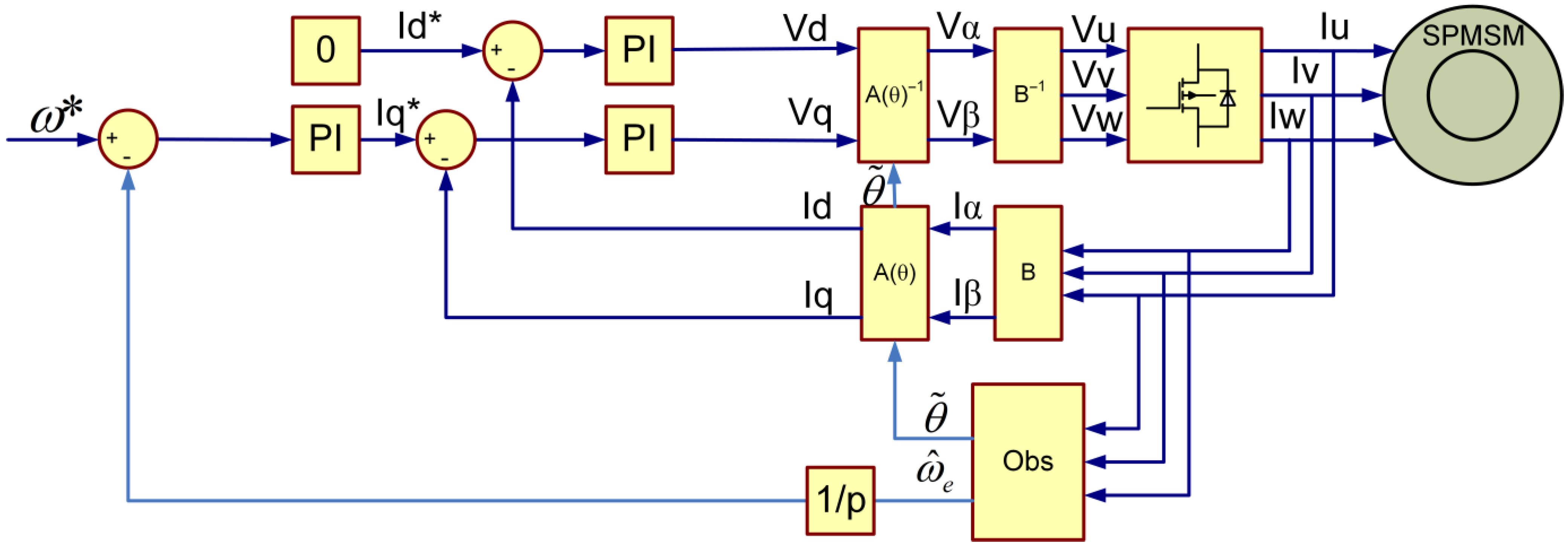
2.1. Model of the Motor under Test, Control Strategy and Current Injection Algorithm
2.2. Simulations
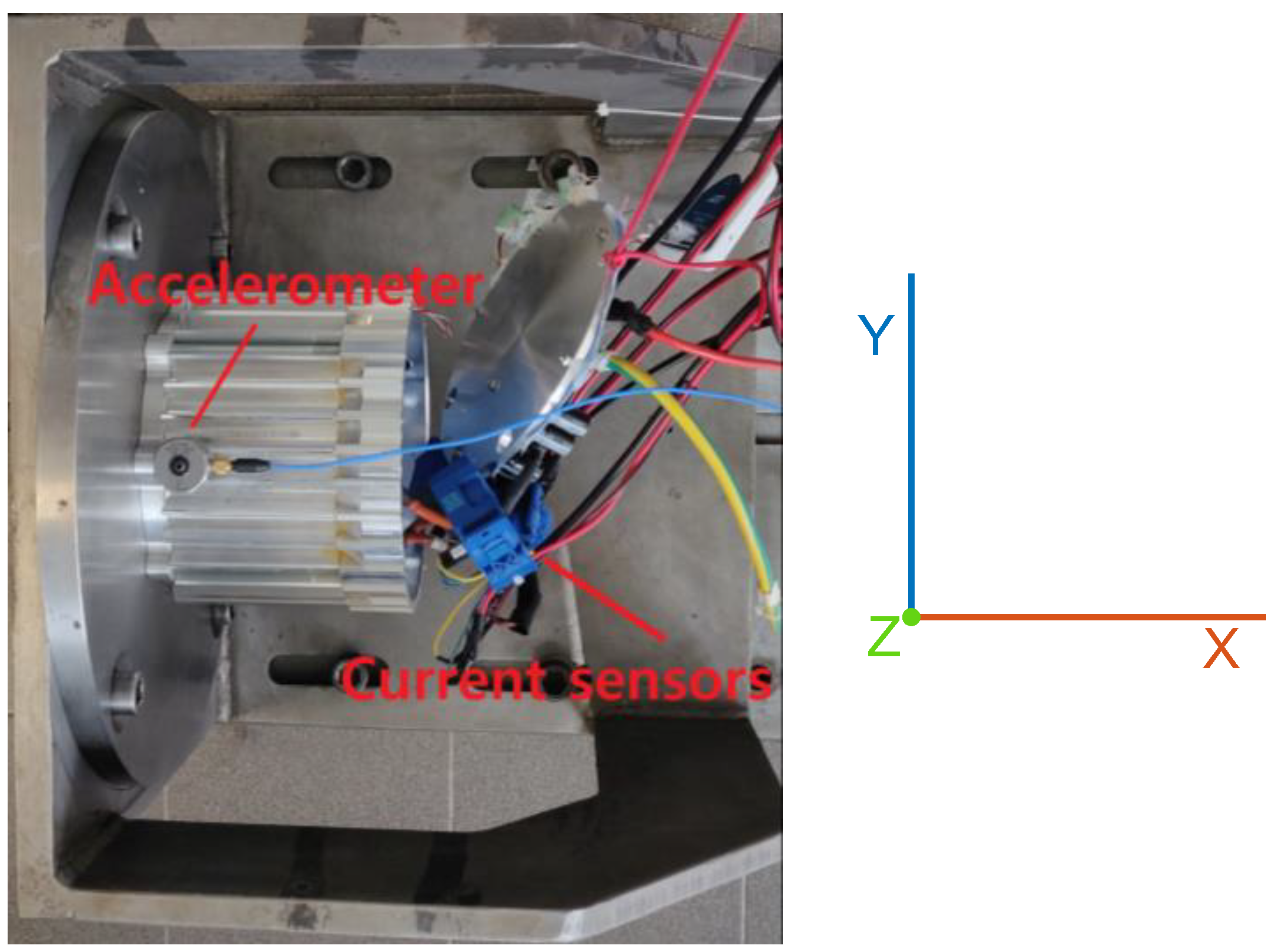
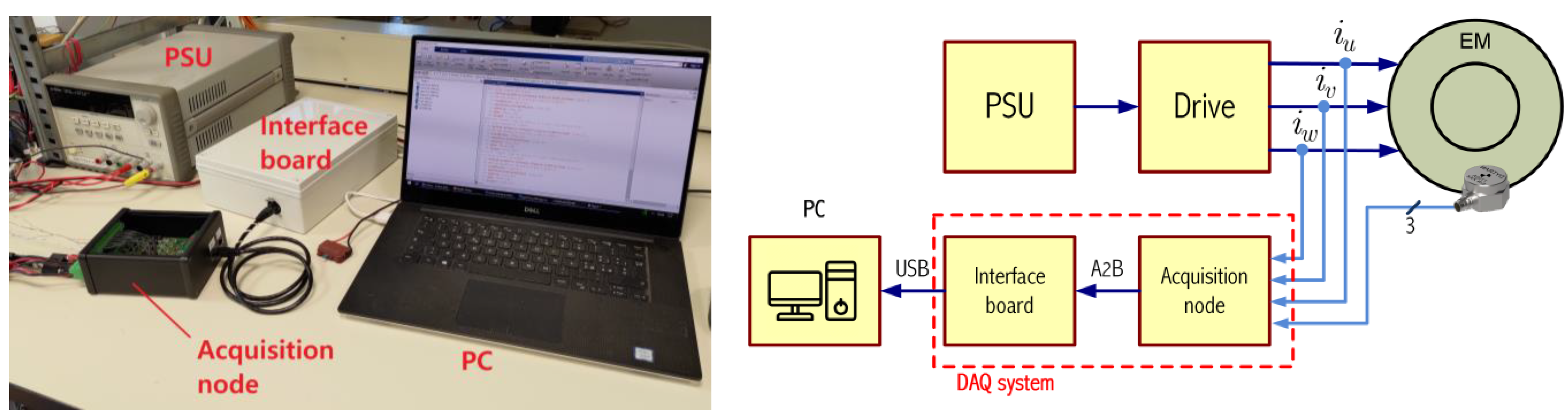
2.3. Measurement System
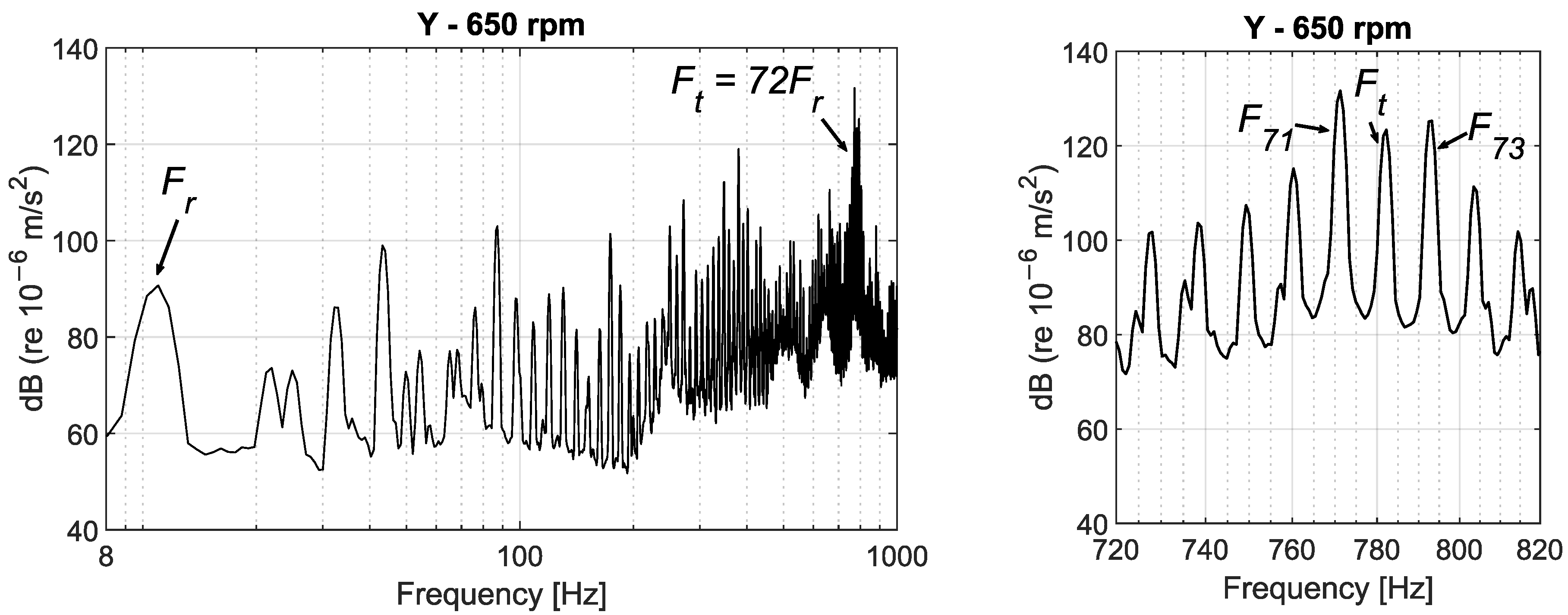
3. Results and Discussion
4. Conclusions
Author Contributions
Funding
Data Availability Statement
Conflicts of Interest
Nomenclature
| Reference acceleration for dB conversion in I.S. | |
| Frequency resolution. | |
| , | Phase and amplitude of injected current. |
| Fr, Ft | Rotor frequency and target frequency to attenuate. |
| Sampling frequency. | |
| , | Currents on – axes. |
| , | Currents on d–q axes. |
| , , | Motor currents. |
| , | Stator inductance on d–q axes. |
| , | Stator magnetic fluxes on d–q axes produced by the d–q currents. |
| , | Stator magnetic fluxes on d–q axes produced by rotor magnets. |
| Electrical speed. | |
| Motor pole pairs. | |
| R | Stator resistance. |
| Rotor position. | |
| Oscillating voltage component with current injection active. | |
| , | Voltages on d–q axes. |
| , | Voltage and current on q axis with current injection active. |
| , | Motor torque and compensating torque with current injection active. |
References
- Gieras, J.F.; Wang, C.; Cho Lai, J. Noise of Polyphase Electric Motors, 1st ed.; CRC Press: Boca Raton, FL, USA, 2005. [Google Scholar]
- Król, E.; Maciążek, M. Identification and Analysis of Noise Sources of Permanent Magnet Synchronous Traction Motor with Interior Permanent Magnet. Energies 2023, 16, 6018. [Google Scholar] [CrossRef]
- Feng, K.; Ji, J.C.; Ni, Q.; Beer, M. A review of vibration-based gear wear monitoring and prediction techniques. Mech. Syst. Signal Process. 2023, 182, 109605. [Google Scholar] [CrossRef]
- Król, E.; Maciążek, M.; Wolnik, T. Review of Vibroacoustic Analysis Methods of Electric Vehicles Motors. Energies 2023, 16, 2041. [Google Scholar] [CrossRef]
- Chi, Y.; Shi, G.; Guo, H.; Yang, N.; Zhu, C.; Cui, M. Design and Performance Investigation of a Vehicle Drive System with a 12/10 Flux-Switching Permanent Magnet Motor. Machines 2022, 10, 1216. [Google Scholar] [CrossRef]
- Zhao, C.; Zuo, Y.; Wang, H.; Hou, Q.; Lee, C.H.T. Smooth Speed Control of Permanent Magnet Synchronous Machine Using Back Propagation Neural Network. World Electr. Veh. J. 2023, 14, 92. [Google Scholar] [CrossRef]
- Battarra, M.; Pizzolante, F.; Frulli, A.; Meleti, S.; Mucchi, E. A model-based approach for gear train whine noise reduction by mesh phasing modification. Inter-Noise Noise-Con Congr. Conf. Proc. 2023, 268, 2672–2679. [Google Scholar] [CrossRef]
- Cristofori, G.; Mucchi, E. Rattle detection in powertrain transmissions based on vibro-acoustical measurements. Mech. Syst. Signal Process. 2024, 212, 111278. [Google Scholar] [CrossRef]
- Stander, C.J.; Heyns, P.S.; Schoombie, W. Using vibration monitoring for local fault detection on gears operating under fluctuating load conditions. Mech. Syst. Signal Process. 2002, 16, 1005–1024. [Google Scholar] [CrossRef]
- Gao, P.; Yan, K.; Liu, H.; Xiang, C. Integrated transmission vibration reduction technology based on the ‘isolating-reducing-optimizing’ method. Mech. Syst. Signal Process. 2024, 206, 110918. [Google Scholar] [CrossRef]
- Chen, X.; Peng, D.; Wu, W.; Liu, H.; Zheng, X. Active Control of Torsional Vibration during Mode Switching of Hybrid Powertrain Based on Adaptive Model Reference. Machines 2022, 10, 647. [Google Scholar] [CrossRef]
- Qin, Y.; Tang, X.; Jia, T.; Duan, Z.; Zhang, J.; Li, Y.; Zheng, L. Noise and vibration suppression in hybrid electric vehicles: State of the art and challenges. Renew. Sustain. Energy Rev. 2020, 124, 109782. [Google Scholar] [CrossRef]
- Tomura, S.; Ito, Y.; Kamichi, K.; Yamanaka, A. Development of Vibration Reduction Motor Control for Series-Parallel Hybrid System; SAE International: Warrendale, PA, USA, 2006. [Google Scholar] [CrossRef]
- Boillat, D.O.; Kolar, J.W.; Muuhlethaler, J. Volume minimization of the main DM/CM EMI filter stage of a bidirectional three-phase three-level PWM rectifier system. In Proceedings of the 2013 IEEE Energy Conversion Congress and Exposition, Denver, CO, USA, 15–19 September 2013; IEEE: Piscataway, NJ, USA, 2013; pp. 2008–2019. [Google Scholar] [CrossRef]
- Vala, S.S.; Mirza, A.B.; Luo, F. A Review on Partial Discharge Phenomenon in Rotating Machines Operated Using WBG Motor Drives. In Proceedings of the 2022 IEEE Transportation Electrification Conference & Expo (ITEC), Anaheim, CA, USA, 15–17 June 2022; IEEE: Piscataway, NJ, USA, 2022; pp. 523–528. [Google Scholar] [CrossRef]
- Jaeger, C.; Grinbaum, I.; Smajic, J. Numerical simulation and measurement of common-mode and circulating bearing currents. In Proceedings of the 2016 XXII International Conference on Electrical Machines (ICEM), Lausanne, Switzerland, 4–7 September 2016; IEEE: Piscataway, NJ, USA, 2016; pp. 486–491. [Google Scholar] [CrossRef]
- Araujo, R.d.S.; de Paula, H.; Rodrigues, R.d.A.; Baccarini, L.M.R.; Rocha, A.V. Premature Wear and Recurring Bearing Failures in an Inverter-Driven Induction Motor—Part I: Investigation of the Problem. IEEE Trans. Ind. Appl. 2015, 51, 4861–4867. [Google Scholar] [CrossRef]
- Concari, L.; Barater, D.; Concari, C.; Toscani, A.; Buticchi, G.; Liserre, M. H8 architecture for reduced common-mode voltage three-phase PV converters with silicon and SiC power switches. In Proceedings of the IECON 2017—43rd Annual Conference of the IEEE Industrial Electronics Society, Beijing, China, October 29–November 1 2017. [Google Scholar] [CrossRef]
- Wang, J.; Wang, L.; Chen, Y.; Wang, Y.; Wang, J. Influence of Periodic Frequency Modulation Technology on Current Harmonic of Drive Motor. In Proceedings of the 2023 IEEE International Conference on Power Science and Technology, ICPST 2023, Kunming, China, 5–7 May 2023; IEEE: Piscataway, NJ, USA, 2023; pp. 141–145. [Google Scholar] [CrossRef]
- Burye, R.S.; Arumalla, R.T.; Figarado, S. Investigation of Torque Ripple in Voltage Source Inverter driven Induction Motor Drive operated with Space Vector based Harmonic Elimination Pulse Width Modulation Scheme. In Proceedings of the 2022 IEEE International Conference on Industrial Technology (ICIT), Shanghai, China, 22–25 August 2022; IEEE: Piscataway, NJ, USA, 2022; pp. 1–6. [Google Scholar] [CrossRef]
- Davari, P.; Zare, F.; Blaabjerg, F. A smart current modulation scheme for harmonic reduction in three-phase motor drive applications. In Proceedings of the 2015 17th European Conference on Power Electronics and Applications (EPE’15 ECCE-Europe), Geneva, Switzerland, 8–10 September 2015; IEEE: Piscataway, NJ, USA, 2015; pp. 1–10. [Google Scholar] [CrossRef]
- Bianchini, C.; Immovilli, F.; Lorenzani, E.; Bellini, A.; Davoli, M. Review of design solutions for internal permanent-magnet machines cogging torque reduction. IEEE Trans. Magn. 2012, 48, 2685–2693. [Google Scholar] [CrossRef]
- Aydin, M.; Gulec, M. Reduction of Cogging Torque in Double-Rotor Axial-Flux Permanent-Magnet Disk Motors: A Review of Cost-Effective Magnet-Skewing Techniques with Experimental Verification. IEEE Trans. Ind. Electron. 2014, 61, 5025–5034. [Google Scholar] [CrossRef]
- Islam, R.; Ortega, A.P. Practical aspects of implementing skew angle to reduce cogging torque for the mass-production of permanent magnet synchronous motors. In Proceedings of the 2017 20th International Conference on Electrical Machines and Systems (ICEMS), Sydney, Australia, 11–14 August 2017; IEEE: Piscataway, NJ, USA, 2017; pp. 1–5. [Google Scholar] [CrossRef]
- El-Refaie, A. Fractional-slot concentrated-windings: A paradigm shift in electrical machines. In Proceedings of the 2013 IEEE Workshop on Electrical Machines Design, Control and Diagnosis (WEMDCD), Paris, France, 11–12 March 2013; IEEE: Piscataway, NJ, USA, 2013; pp. 24–32. [Google Scholar] [CrossRef]
- Wang, J.; Patel, V.I.; Wang, W. Fractional-slot permanent magnet brushless machines with low space harmonic contents. IEEE Trans. Magn. 2014, 50, 1–9. [Google Scholar] [CrossRef]
- El-Refaie, A.M. Fractional-slot concentrated-windings synchronous permanent magnet machines: Opportunities and challenges. IEEE Trans. Ind. Electron. 2010, 57, 107–121. [Google Scholar] [CrossRef]
- Salminen, P. Fractional Slot Permanent Magnet Synchronous Motors for Low Speed Applications; Lappeenrannan Teknillinen Yliopisto: Lappeenranta, Finland, 2004. [Google Scholar]
- De Donato, G.; Giulii Capponi, F.; Rivellini, G.A.; Caricchi, F. ntegral-Slot Versus Fractional-Slot Concentrated-Winding Axial-Flux Permanent-Magnet Machines: Comparative Design, FEA, and Experimental Tests. IEEE Trans. Ind. Appl. 2012, 48, 1487–1495. [Google Scholar] [CrossRef]
- Zhao, G.; Hua, W.; Zhu, X.; Zhang, G. The Influence of Dummy Slots on Stator Surface-Mounted Permanent Magnet Machines. IEEE Trans. Magn. 2017, 53, 1–5. [Google Scholar] [CrossRef]
- Jabbari, A. The Effect of Dummy Slots on Machine Performance in Brushless Permanent Magnet Machines: An Analytical, Numerical, and Experimental Study. Iran. J. Electr. Electron. Eng. 2022, 18, 1–11. [Google Scholar] [CrossRef]
- Hasan, I.; Sozer, Y.; Ortega, A.P.; Paul, S.; Islam, R. Investigation of design based solutions to reduce vibration in permanent magnet synchronous machines with low order radial forces. In Proceedings of the 2017 IEEE Energy Conversion Congress and Exposition (ECCE), Cincinnati, OH, USA, 1–5 October 2017; IEEE: Piscataway, NJ, USA, 2017; pp. 5431–5437. [Google Scholar] [CrossRef]
- Soyaslan, M.; Avsar, Y.; Fenercioglu, A.; Eldogan, O. Cogging Torque Reduction in External Rotor PM Synchronous Motors by Optimum Pole Embrace. In Proceedings of the 2019 3rd International Symposium on Multidisciplinary Studies and Innovative Technologies (ISMSIT), Ankara, Turkey, 11–13 October 2019; IEEE: Piscataway, NJ, USA, 2019; pp. 1–4. [Google Scholar] [CrossRef]
- Upadhayay, P.; Rajagopal, K.R. Torque ripple reduction using magnet pole shaping in a surface mounted Permanent Magnet BLDC motor. In Proceedings of the 2013 International Conference on Renewable Energy Research and Applications (ICRERA), Madrid, Spain, 20–23 October 2013; IEEE: Piscataway, NJ, USA, 2013; pp. 516–521. [Google Scholar] [CrossRef]
- Kim, T.-W.; Chang, J.-H. Influence of Cogging Torque Reduction Method on Torque Ripple in a Surface-Mounted Permanent Magnet Synchronous Motor. J. Magn. 2012, 17, 109–114. [Google Scholar] [CrossRef]
- Patel, A.N.; Kapil, A. Analysis of Cogging Torque Reduction by Increasing Stator Slot Depth in Brushless DC Motor. In Proceedings of the 2016 IEEE 1st International Conference on Power Electronics, Intelligent Control and Energy Systems (ICPEICES), Delhi, India, 4–6 July 2016; p. 242. [Google Scholar]
- Lee, S.H.; Hong, J.P.; Hwang, S.M.; Lee, W.T.; Lee, J.Y.; Kim, Y.K. Optimal Design for Noise Reduction in Interior Permanent-Magnet Motor. IEEE Trans. Ind. Appl. 2009, 45, 1954–1960. [Google Scholar] [CrossRef]
- Saxena, A.; Fernandes, B.G. Noise and cogging torque reduction in brushless DC ceiling fan. In Proceedings of the 2015 18th International Conference on Electrical Machines and Systems (ICEMS), Pattaya, Thailand, 25–28 October 2015; IEEE: Piscataway, NJ, USA, 2015; pp. 1334–1338. [Google Scholar] [CrossRef]
- Sumega, M.; Rafajdus, P.; Stulrajter, M. Current Harmonics Controller for Reduction of Acoustic Noise, Vibrations and Torque Ripple Caused by Cogging Torque in PM Motors under FOC Operation. Energies 2020, 13, 2534. [Google Scholar] [CrossRef]
- Zhong, Z.; Jiang, S.; Zhou, Y.; Zhou, S. Active torque ripple reduction based on an analytical model of torque. IET Electr. Power Appl. 2017, 11, 331–341. [Google Scholar] [CrossRef]
- Qian, W.; Panda, S.K.; Xu, J.-X. Torque Ripple Minimization in PM Synchronous Motors Using Iterative Learning Control. IEEE Trans. Power Electron. 2004, 19, 272–279. [Google Scholar] [CrossRef]
- Gómez-Espinosa, A.; Hernández-Guzmán, V.M.; Bandala-Sánchez, M.; Jiménez-Hernández, H.; Rivas-Araiza, E.A.; Rodríguez-Reséndiz, J.; Herrera-Ruíz, G. A New Adaptive Self-Tuning Fourier Coefficients Algorithm for Periodic Torque Ripple Minimization in Permanent Magnet Synchronous Motors (PMSM). Sensors 2013, 13, 3831–3847. [Google Scholar] [CrossRef]
- Zhang, X.; Liu, H.; Zhan, Z.; Wu, Y.; Zhang, W.; Taha, M.; Yan, P. Modelling and active damping of engine torque ripple in a power-split hybrid electric vehicle. Control. Eng. Pract. 2020, 104, 104634. [Google Scholar] [CrossRef]
- Kuo, S.M.; Morgan, D.R. Active noise control: A tutorial review. Proc. IEEE 1999, 87, 943–975. [Google Scholar] [CrossRef]
- Shen, M.; Xie, F.; Zhang, W.; Zhang, J. Torque Ripple Reduction of Permanent Magnet Synchronous Motor Based on Least Mean Square Algorithm. In International Joint Conference on Energy, Electrical and Power Engineering; Springer: Singapore, 2023; pp. 638–646. [Google Scholar] [CrossRef]
- Kwong, R.H.; Johnston, E.W. A variable step size LMS algorithm. IEEE Trans. Signal Process. 1992, 40, 1633–1642. [Google Scholar] [CrossRef]
- Huang, Y. Adaptive Signal Processing—Applications to Real-World Problems; Springer: Berlin/Heidelberg, Germany, 2003. [Google Scholar] [CrossRef]
- Ferrer, M.; Gonzalez, A.; de Diego, M.; Pinero, G. Fast Affine Projection Algorithms for Filtered-x Multichannel Active Noise Control. IEEE Trans. Audio Speech Lang. Process. 2008, 16, 1396–1408. [Google Scholar] [CrossRef]
- Yang, F.; Cao, Y.; Wu, M.; Albu, F.; Yang, J. Frequency-Domain Filtered-x LMS Algorithms for Active Noise Control: A Review and New Insights. Appl. Sci. 2018, 8, 2313. [Google Scholar] [CrossRef]
- Elliott, S.; Darlington, P. Adaptive cancellation of periodic, synchronously sampled interference. IEEE Trans. Acoust. 1985, 33, 715–717. [Google Scholar] [CrossRef]
- Schreiber, M.; Hecker, S.; Sentpali, S.; Gerling, D. Modelling and reduction of current harmonics in permanent magnet synchronous machines during active noise cancellation. In Proceedings of the 2022 IEEE/ASME International Conference on Advanced Intelligent Mechatronics (AIM), Sapporo, Japan, 11–15 July 2022; IEEE: Piscataway, NJ, USA, 2022; pp. 593–598. [Google Scholar] [CrossRef]
- Chaplin, B. The cancellation of repetitive noise and vibration. In INTER-NOISE and NOISE-CON Congress and Conference Proceedings; Institute of Noise Control Engineering: Miami, FL, USA, 1980; pp. 699–702. [Google Scholar]
- Mattavelli, P.; Tubiana, L.; Zigliotto, M. Torque-Ripple Reduction in PM Synchronous Motor Drives Using Repetitive Current Control. IEEE Trans. Power Electron. 2005, 20, 1423–1431. [Google Scholar] [CrossRef]
- ISO 5349-1:2001; Mechanical Vibration—Measurement and Evaluation of Human Exposure to Hand-Transmitted Vibration. International Organization for Standardization: Geneva, Switzerland, 2001. Available online: https://www.iso.org/standard/32355.html (accessed on 29 July 2024).
- Wu, J.; Wei, H.; Zhang, Y.; Wei, H. Sensorless vector control of permanent magnet synchronous motor based on model reference adaptive system. In Proceedings of the 2017 3rd IEEE International Conference on Computer and Communications (ICCC), Chengdu, China, 13–16 December 2017; IEEE: Piscataway, NJ, USA, 2017; pp. 2879–2883. [Google Scholar] [CrossRef]
- Rocchi, N.; Toscani, A.; Chiorboli, G.; Pinardi, D.; Binelli, M.; Farina, A. Transducer Arrays over A2B Networks in Industrial and Automotive Applications: Clock Propagation Measurements. IEEE Access 2021, 9, 118232–118241. [Google Scholar] [CrossRef]
- Toscani, A.; Rocchi, N.; Pinardi, D.; Binelli, M.; Saccenti, L.; Farina, A.; Pavoni, S.; Vanali, M. Low-cost Structural Health Monitoring System for Smart Buildings. In Proceedings of the 2022 Second International Conference on Sustainable Mobility Applications, Renewables and Technology (SMART), Cassino, Italy, 23–25 November 2022; IEEE: Piscataway, NJ, USA, 2022; pp. 1–7. [Google Scholar] [CrossRef]
- Toscani, A.; Rocchi, N.; Pinardi, D.; Binelli, M.; Saccenti, L.; Farina, A.; Pavoni, S.; Vanali, M. Low-Cost Condition Monitoring System for Smart Buildings and Industrial Applications. IEEE Trans. Ind. Appl. 2024, 60, 1870–1878. [Google Scholar] [CrossRef]
- Toscani, A.; Immovilli, F.; Pinardi, D.; Cattani, L. A Novel Scalable Digital Data Acquisition System for Industrial Condition Monitoring. IEEE Trans. Ind. Electron. 2023, 71, 7975–7985. [Google Scholar] [CrossRef]
- Pinardi, D.; Rocchi, N.; Toscani, A.; Binelli, M.; Chiorboli, G.; Farina, A.; Cattani, L. An Innovative Architecture of Full-Digital Microphone Arrays Over A2B Network for Consumer Electronics. IEEE Trans. Consum. Electron. 2022, 68, 200–208. [Google Scholar] [CrossRef]
- Rocchi, N.; Toscani, A.; Pinardi, D.; Binelli, M.; Chiesi, L.; Farina, A.; Bonomi, E.; Tronchin, L. A Modular, Low Latency, A2B-based Architecture for Distributed Multichannel Full-Digital Audio Systems. In Proceedings of the 2021 Immersive and 3D Audio: From Architecture to Automot (I3DA), Bologna, Italy, 8–10 September 2021; IEEE: Piscataway, NJ, USA, 2021; pp. 1–8. [Google Scholar] [CrossRef]
- Pinardi, D.; Toscani, A.; Binelli, M.; Saccenti, L.; Farina, A.; Cattani, L. Full-Digital Microphone Meta-Arrays for Consumer Electronics. IEEE Trans. Consum. Electron. 2023, 69, 640–648. [Google Scholar] [CrossRef]
- Belicchi, C.; Opinto, A.; Martalo, M.; Tira, A.; Pinardi, D.; Farina, A.; Ferrari, G. ANC: A Low-Cost Implementation Perspective. In SAE Technical Papers; SAE International: Warrendale, PA, USA, 2022. [Google Scholar] [CrossRef]
- Voltolini, E.; Pinardi, D.; Toscani, A.; Binelli, M.; Farina, A.; Ferrari, J.; Maglia, S.; Zenaro, A.; Calzavacca, E. Design of an Active Noise Reduction System for a Cogeneration Plant. In Proceedings of the 2023 Immersive and 3D Audio: From Architecture to Automotive (I3DA), Bologna, Italy, 5–7 September 2023; IEEE: Piscataway, NJ, USA, 2023; pp. 1–7. [Google Scholar] [CrossRef]


| Specification | Value |
|---|---|
| Nominal voltage | 30 V |
| Nominal power | 3000 W |
| Voltage constant | 8.67 mV/rpm |
| Nominal speed | 3500 rpm |
| Number of pole pairs | 4 |
| Nominal current | 58 A |
| Nominal torque | 8.1 Nm |
| Stator resistance | 8.2 mΩ |
| Stator inductance | 32 µH |
| Specification | Value |
|---|---|
| Type | IEPE |
| Sensitivity | 1000 mV/g |
| Measurement range | ±5 g peak |
| Frequency range | X, Y: 0.4 Hz–6 kHz Z: 0.4 Hz–3 kHz |
| Maximum Output Voltage | ±5 V |
| Excitation | 18–30 V DC |
| Specification | Value |
|---|---|
| Primary current | 200 A |
| Secondary current | 100 mA |
| Nominal sensitivity | 0.5 mA/A |
| Sensitivity error | ±0.1% |
| Frequency bandwidth (−3 dB) | 100 kHz |
| Supply voltage (nominal) | ±15 V |
| Closed loop (compensated) | Yes |
| Specification | Value |
|---|---|
| Architecture | 24-bit delta-sigma |
| Number of channels | 8, simultaneous sampling |
| Analog bandwidth | 70 kHz |
| Maximum sampling rate | Up to 144 kS/s |
| DC accuracy—offset drift | 0.8 µV/°C |
| DC accuracy—gain drift | 1.3 ppm/°C |
| Serial interface | SPI or frame sync |
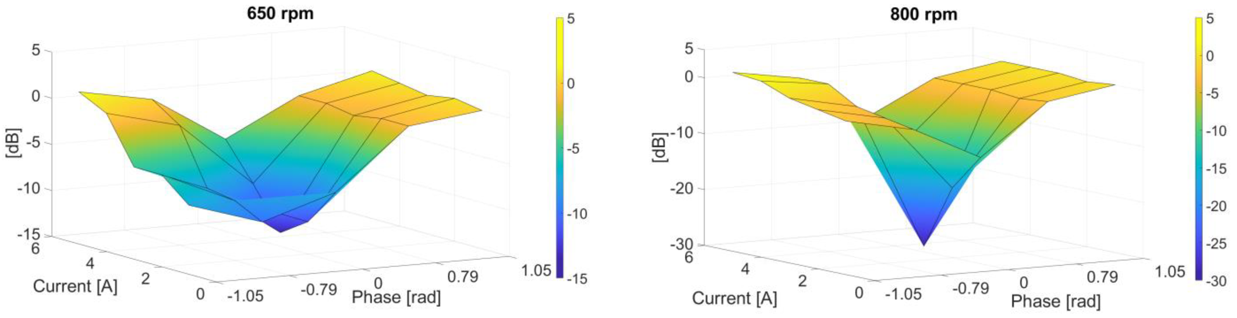
| (a) 650 rpm | |||||
| Modulation index (KINJ) | ) [rad] | ||||
| −1.05 | −0.79 | 0 | 0.79 | 1.05 | |
| 0.05 | −7.5 dB | −10.0 dB | −7.5 dB | −1.0 dB | 0 dB |
| 0.06 | −5.0 dB | −8.5 dB | −11.5 dB | −1.0 dB | 0.5 dB |
| 0.07 | −5.0 dB | −8.0 dB | −13.5 dB | −1.5 dB | 0 dB |
| 0.08 | 0 dB | −2.0 dB | −9.0 dB | −1.0 dB | 0.5 dB |
| 0.09 | 1.5 dB | 0 dB | −5.0 dB | −1.0 dB | 1.0 dB |
| (b) 800 rpm | |||||
| Modulation index (KINJ) | ) [rad] | ||||
| −1.05 | −0.79 | 0 | 0.79 | 1.05 | |
| 0.05 | −2.5 dB | −5.0 dB | −11.0 dB | −2.0 dB | 0 dB |
| 0.06 | −1.5 dB | −4.0 dB | −17.5 dB | −2.5 dB | −0.5 dB |
| 0.07 | −0.5 dB | −3.0 dB | −29.0 dB | −2.0 dB | 0 dB |
| 0.08 | 1.5 dB | 0 dB | −13.0 dB | −2.0 dB | 0 dB |
| 0.09 | 2.0 dB | 0 dB | −8.0 dB | −2.0 dB | 0 dB |
| Motor Speed [rpm] | AVC System Condition | Overall Acceleration Level [dB] |
|---|---|---|
| 650 | OFF | 77.2 |
| 650 | ON | 75.5 |
| 800 | OFF | 76.3 |
| 800 | ON | 72.9 |
Disclaimer/Publisher’s Note: The statements, opinions and data contained in all publications are solely those of the individual author(s) and contributor(s) and not of MDPI and/or the editor(s). MDPI and/or the editor(s) disclaim responsibility for any injury to people or property resulting from any ideas, methods, instructions or products referred to in the content. |
© 2024 by the authors. Licensee MDPI, Basel, Switzerland. This article is an open access article distributed under the terms and conditions of the Creative Commons Attribution (CC BY) license (https://creativecommons.org/licenses/by/4.0/).
Share and Cite
Bassani, M.; Pinardi, D.; Toscani, A.; Manconi, E.; Concari, C. Active Vibration Control via Current Injection in Electric Motors. Electronics 2024, 13, 3442. https://doi.org/10.3390/electronics13173442
Bassani M, Pinardi D, Toscani A, Manconi E, Concari C. Active Vibration Control via Current Injection in Electric Motors. Electronics. 2024; 13(17):3442. https://doi.org/10.3390/electronics13173442
Chicago/Turabian StyleBassani, Marco, Daniel Pinardi, Andrea Toscani, Elisabetta Manconi, and Carlo Concari. 2024. "Active Vibration Control via Current Injection in Electric Motors" Electronics 13, no. 17: 3442. https://doi.org/10.3390/electronics13173442
APA StyleBassani, M., Pinardi, D., Toscani, A., Manconi, E., & Concari, C. (2024). Active Vibration Control via Current Injection in Electric Motors. Electronics, 13(17), 3442. https://doi.org/10.3390/electronics13173442