Article

HDCCT: Hybrid Densely Connected CNN and Transformer for Infrared and Visible Image Fusion

1
School of Rail Transportation, Shandong Jiaotong University, Jinan 250357, China
2
State Key Laboratory of Rail Traffic Control and Safety, Beijing Jiaotong University, Beijing 100044, China
3
CRSC Research and Design Institute Group Co., Ltd., Beijing 100070, China
*
Author to whom correspondence should be addressed.
Electronics 2024, 13(17), 3470; https://doi.org/10.3390/electronics13173470
Submission received: 12 June 2024 / Revised: 15 August 2024 / Accepted: 23 August 2024 / Published: 31 August 2024

Abstract

:
Multi-modal image fusion is a methodology that combines image features from multiple types of sensors, effectively improving the quality and content of fused images. However, most existing deep learning fusion methods need to integrate global or local features, restricting the representation of feature information. To address this issue, a hybrid densely connected CNN and transformer (HDCCT) fusion framework is proposed. In the proposed HDCCT framework, the network of the CNN-based blocks obtain the local structure of the input data, and the transformer-based blocks obtain the global structure of the original data, significantly improving the feature representation. In the fused image, the proposed encoder–decoder architecture is designed for both the CNN and transformer blocks to reduce feature loss while preserving the characterization of all-level features. In addition, the cross-coupled framework facilitates the flow of feature structures, retains the uniqueness of information, and makes the transform model long-range dependencies based on the local features already extracted by the CNN. Meanwhile, to retain the information in the source images, the hybrid structural similarity (SSIM) and mean square error (MSE) loss functions are introduced. The qualitative and quantitative comparisons of grayscale images with infrared and visible image fusion indicate that the suggested method outperforms related works.

1. Introduction

Image fusion uses the characteristics of a variety of different sensors to combine different types of images to enhance the details, color, edge, and other features. Therefore, this technology can be applied in medicine [1], surveillance [2], remote sensing [3], and other fields [4,5]. Unlike multi-focus and multi-exposure techniques, multi-modal image fusion uses various imaging principles with multiple sensors to capture information from different scenes. Infrared, visible, magnetic resonance imaging (MRI), and computed tomography (CT) sensors are appropriate for multi-modal image fusion. Their signals are from different modalities to reflect different characteristics of a situation to make the visual features robust. Infrared and visible image fusion is famous for its common applications and effective results. Two mainstream techniques for infrared and visible image fusion include traditional and learned-based methods.
Classical fusion methods include multi-scale transformation-based [6], saliency-based [7], sparse representation-based [8], and hybrid-based methods [9]. In the field of infrared and visible image fusion, various recent learned-based methods utilize CNNs [10,11,12,13,14] to deal with the shortcomings of traditional methods. The feature extraction ability of CNNs has remarkable performance for obtaining valuable information for the image features. Xu et al. [15] proposed U2Fusion to deal with the multi-modal, multi-exposure, and multi-focus conditions with the same CNN-based architecture with feature extraction and information measurement. However, these methods cannot deal with diverse fusion tasks, such as multi-exposure and multi-focus fusion. Li et al. [16] established an end-to-end residual fusion network to fuse infrared and visible images, and a loss function was designed for the proposed architecture to enhance the expression of features. Nevertheless, these CNN-based methods cannot deal with the challenge of the dearth of ground truth, which will lead to complex fusion strategies to improve the fusion ability.
To address the issue in CNN-based methods for the fusion of visible and infrared images, the generative adversarial network (GAN) has been used in recent years [17,18,19,20,21]. Ma et al. [18] established fusion as an adversarial game to keep the visible and infrared images, utilizing a generator and a discriminator to obtain the fusion results. Gao et al. [17] proposed an effective framework with the densely connected disentangled representation generative adversarial network (DCDR-GAN), striping the details and the model features through disentangled representation. However, CNN-based and GAN-based fusion methods for visible and infrared images are all based on convolution operations, mainly focusing on extracting local feature information to fuse images. Moreover, methods based on convolution operations restrict the capacity to extract the features from the global information, which limits the image representation of color and texture and the distinction between feature continuity and region correlation.
To remedy the defect of CNNs, transformers are introduced to enlarge the receptive fields, which has achieved significant performance results in visible and infrared fusion [22,23,24,25]. Transformers integrate the global contextual information of multi-modal image features, capturing the most prominent information for different sensors to fuse the features of parallel blocks. Vs et al. [26] proposed using the image fusion transformer (IFT) method for multi-scale image fusion. However, the IFT is designed based on the existing RFN-Nest architecture, which is still a whole CNN architecture. Although the spatial transformer (ST) is introduced for global feature extraction, the cascade connection of the convolution operations before and after the ST block weakens the global feature representation of the shallow layers and deep layers of the data features [27,28].
To address the absence of fusion of local and global features for visible and infrared image fusion in previous publications, we present a novel non-local CNN–transformer fusion framework (HDCCT). There are two main structures of the proposed architecture. The CNN blocks extract the local information of the image features for the corner class and region class of the local area, and the transformer blocks can extract the global image feature information of color, texture, and shape. The proposed HDCCT focuses on the optimizer for multiple features. With multi-scale feature fusion and dense connections, the hybrid architecture sufficiently integrates the global and local information by feature extraction. The sequential hybrid method of CNN and transformer ensures local feature relationships and correctly represents global features while reducing noise in the fused images. The fusion architecture with the CNN and transformer solves the mosaic phenomenon, unclear edges for the CNN blocks, and inadequate detail and texture for the transformer blocks. The architecture of the proposed HDCCT framework is displayed in Figure 1. In this paper, structural similarity (SSIM) loss is introduced for local feature loss, which mainly concentrates on pixel loss for fusion images. Moreover, mean squared error (MSE) loss is applied for global feature loss. With the proposed HDCCT method, the global and local features of visible and infrared images can be integrated to obtain fusion results. The contributions of this paper are provided below:
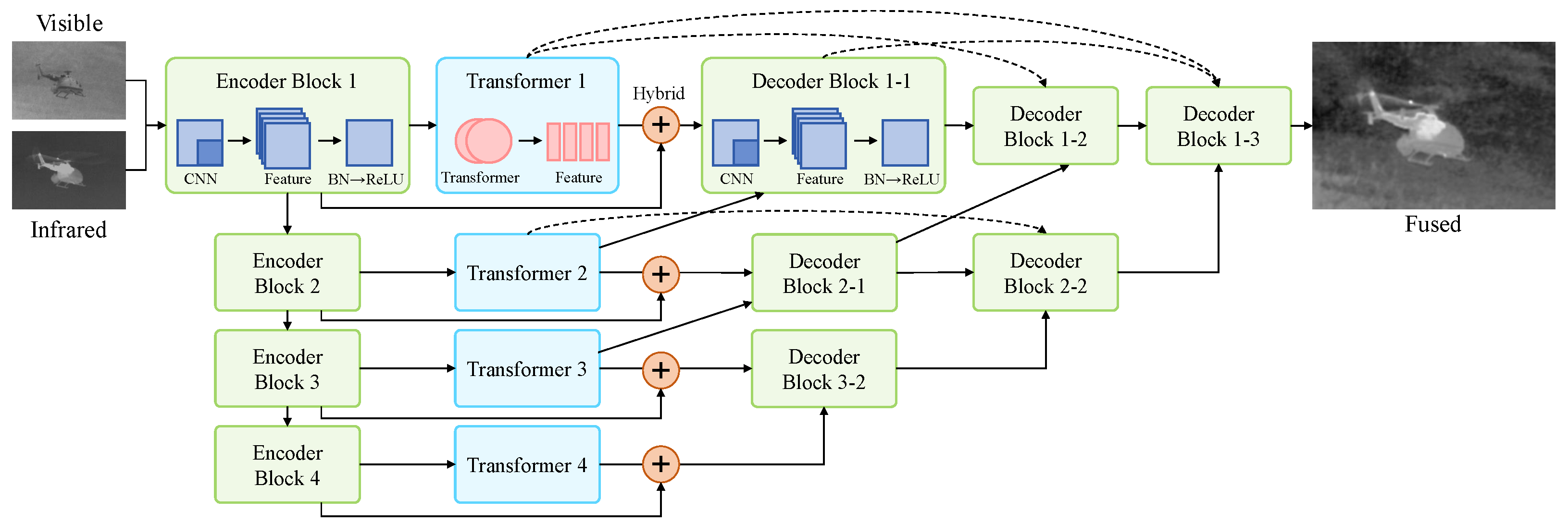
  • A new fusion architecture for multi-modal image fusion including a CNN for local information and a transformer for global information is presented. The hybrid architecture integrates local and global information, sufficiently integrating the information through feature extraction.
  • The encoder–decoder architecture is designed for image fusion for both the CNN and the transformer. The encoder–decoder of the CNN use long connections of features from the alignment of different depths to generate local feature information.
  • The optimizer enhances the feature representation capacity to extract the global and local features for multi-model fusion. MSE and SSIM losses are used for local and global feature loss, which mainly includes the pixel loss for fusion images.
The other components of this paper are arranged as follows: Section 2 gives similar works including CNNs and transformers for image fusion. Section 3 provides details about the proposed framework. Section 4 explains the experiments and evaluations, including the whole experimental setup and the generating methodology that was tested on the TNO and RoadScene datasets. Furthermore, Section 4 describes the ablation experiments in detail. Section 5 presents the conclusion.

2. Related Works

2.1. CNN-Based Methods for Image Fusion

The CNN has been introduced to deal with problems of traditional fusion methods, such as hand-crafted features and time-consuming transformation. Many works have used CNNs for the fusion of images, which breaks through the limits of the traditional methods to extract local features. The dataset for image fusion is also very essential for the determination of ground truth with the fused images. Ram et al. [29] introduced the unsupervised deep learning framework for multi-exposure fusion without the ground truth of fusion images, which includes the encoder and decoder layers to deal with the determination of ground truth with the fused images. However, these simple networks lack great feature extraction ability, and valuable feature information is lost in the middle layers. Li et al. [10] introduced a deep learning network with dense blocks and a CNN, which overcomes the drawbacks of these methods. However, these CNN-based fusion methods are according to common rules such as addition, maximum, minimum, and l 1 -norm operations, which limit the representation of the fusion methods. Li et al. [30] used the spatial attention models and the nest connection-based network for visible and infrared image fusion, preserving satisfactory information from the input data from the multi-scale aspect. CNN-based methods have overcome the problems of typical methods for hand-crafted features and time-consuming transform operations. However, these CNN-based methods only extract local features, which neglects to account for global information, including the edge, light, and the distinction between foreground and background.

2.2. Transformer-Based Methods for Image Fusion

The basis of the transformer is the introduction of a self-attention mechanism to extract global features, distinct from CNNs and RNNs for local information. The input of the transformer can usually directly operate on pixels to obtain the initial embedding vector, which is closer to how people perceive the outside world. Transformer models can learn relevant information in several representation subspaces for different purposes. Computer vision tasks using transformers have demonstrated outstanding efficiency in natural language processing (NLP) [31]. Unlike CNNs and RNNs, which use ensembles for local information, the self-attention mechanism serves as the basis for the transformer for global feature information. Xiao et al. [32] asserted that early visual processing for constraining convolutions balances the biases and the feature learning capacity with transformer blocks, resulting in remarkable model complexity and object identification performance. However, these methods only consider the information of global features, leaving out local feature expression. Peng et al. [33] developed an interactive methodology to merge local convolutional features with transformer-based global information while retaining both global and local representations. However, the existing fusion methods need to improve local and global information flow between the two branches of the CNN and the transformer in order to better incorporate feature information. The transformer has also been used for image fusion in recent years for its remarkable performance in global information extraction [26,34]. TransMEF [34], which combines a CNN encoder and a transformer model, performs well in both subjective and objective multi-exposure image fusion evaluations. However, most current image fusion frameworks rely on CNN encoders and decoders. The presented transformer blocks are only part of the CNN encoder; therefore, the transformer global information extraction capabilities are not fully utilized.

2.3. Multi-Modal Methods for Image Fusion

Multi-modal image fusion uses various sources of images to obtain an exceptional fused image with various types of information combined. Visible and infrared image fusion yields detailed texturing and temperature data for objects. The traditional fusion methods for infrared and visible image fusion can be summarized into several fields, including multi-scale transform [35], sparse representation [36,37], hybrid models [38], and other methods [2]. Currently, multi-modal image fusion incorporates deep learning works, achieving remarkable performance for its robust feature representation abilities. In computer vision fields, the integration of a CNN and a transformer is firstly applied, such as object detection [39], segmentation [40], and classification [41]. Nowadays, CNN–transformer combinations are introduced into image fusion for their robust feature extraction ability. Jin et al. [27] combines U-net and a transformer for feature extraction and information reconstruction modules for multi-focus image fusion. However, this single branch extracts insufficient information of local and global features because backpropagation within the training process disturbs the flow of local and global information. Moreover, the decoder of this network only has a U-net decoder, ignoring the decoder of the transformer for the global features, which further causes global feature information decay. Yuan et al. [28] proposed to use the CNN encoder and transformer decoder for image fusion. Although this method integrates global and local features, the combination with this set encodes the local features and decodes the global features, which weakens multi-modal image fusion. Qu et al. [34] used the CNN and transformer encoder and CNN decoder with Gamma transform, the Fourier transformer, and global region shuffling for multi-exposure image fusion. These three transforms lead to the networks significantly increasing the training and inference complexity and cost. Moreover, the decoder has only two convolutional blocks without the transformer block, which certainly decodes the local information, but decoding the global information is required to obtain the fusion results.

3. Methodology

3.1. Overview of Proposed Architecture

To deal with the issue of the related works, this paper proposes a hybrid densely connected CNN and transformer (HDCCT) framework for image fusion. The proposed framework has two main blocks, the CNN and the transformer, which extract the local and global features separately. According to the architecture in Figure 1, the input infrared and visible images are first extracted to the encoders, and the same size of infrared and visible images are fused to the encoder output features. In this paper, the inputs are infrared and visible images from the TNO dataset and the RoadScene dataset, and the size of the input infrared and visible images is 256 × 256 . The encoder output features are separately put into the CNN and the transformer, which further utilize the local and global image features. The outputs of the decoders are finally combined into the final fusion results with the add operation.
The encoder and the decoder of the CNN blocks are symmetrical architectures. The encoder of the CNN has four convolutional layers, and the size of features decreases through the convolution operation. The CNN blocks integrate the encoder features with the decoder features of the same size. The transformer encoder establishes the encoder of the transformer block with average pooling to control the size of the features. The transformer block with the upscale operation is the decoder of the transformer block. The CNN processes input data and extracts local features; then, it passes these features as inputs to the transformer. This method allows the transformer to model long-range dependencies based on the extracted local features. Through the hybrid module, the output of the CNN and transformer encoders concatenate into the decoders. In this way, the global and local information can flow in the two branches to enhance the representation of the image features.

3.2. Details of HDCCT

The CNN encoder block is composed of four encoder blocks, each containing a convolutional layer with a kernel size of 3 × 3 , subsequent to ReLU and max pooling operations. The architecture of the proposed CNN blocks is in Figure 2.

3.2.1. Encoder and Decoder Architecture of HDCCT

The detailed architecture of the CNN branch in the proposed architecture comprises the encoder and decoder network. The encoder is composed of four down-sampling blocks x i ( i = 1 , 2 , 3 , 4 ) , which decrease the width and height by half at every down-sampling block. The down-sampling block is the essential part of the CNN branch encoder and consists of the 3 × 3 convolution operation for feature extraction. ReLU is introduced as the activation function, and reflection padding complements the feature size.
The decoder network has a symmetrical architecture, with four up-sampling blocks D i ( i = 1 ,   2 ,   3 ,   4 ) . The deconvolution operation is used for the up-sampling block with the kernel size of 2, and the feature size is doubled at every block. Moreover, ReLU is also applied as the activation function, and the feature size is complemented with reflection padding. The indexes of the output of encoder down-sampling blocks E i ( i = 1 ,   2 ,   3 ,   4 ) and input of decoder up-sampling blocks D 5 i ( i = 1 ,   2 ,   3 ,   4 ) have the same size. These CNN blocks also introduce the RFN-Nest architecture, obtaining rich feature information and better network convergence performance. The features from the encoder concatenate to the decoder with the same size to promote feature information flow in the deep layers. The decoder and the encoder CNN networks are symmetrical architectures for feature extraction in image fusion. In this way, the CNN branch’s high-resolution output is the same as the input images.

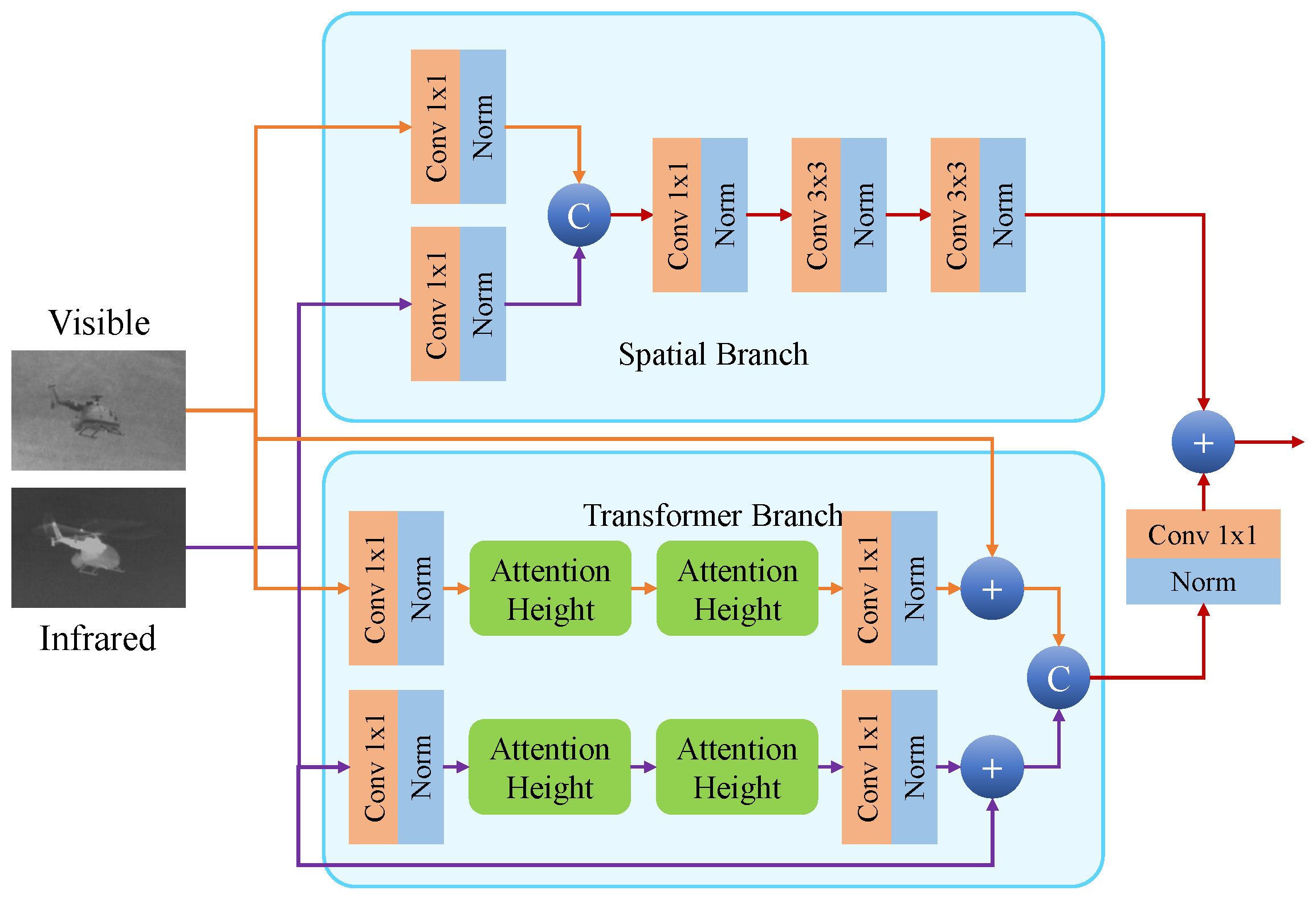
3.2.2. Architecture of Transformer

The transformer block used includes a transformer branch and a spatial branch, in which local features are captured by convolutional blocks. In the transformer branch, the global structure is captured through an axial attention mechanism. The axial attention mechanism performs self-attention on the vertical and horizontal axes, significantly reducing computational consumption and improving sensitivity to position. Figure 3 indicates the architecture of the transformer blocks. By fusing the obtained local and global features, enhanced local structure and global information can be obtained, and the fused image can be obtained.

3.3. Feature Fusion for Multi-Modal Image Fusion

Features from the hybrid CNN–transformer parallel network are fused in two parts: the outputs of encoder block4 and decoder block4 of the two branches. The outputs of encoder block4 are merged with the input of decoder block1 of the CNN and the transformer. Feed-forward and backpropagation promote feature information flow in the two branches. The channels of decoder block4 of the CNN branch with the fused images are matched with 1 × 1 convolution and normalization. These two features are added together to preserve enhanced local- and global-context information for the fused feature map.

3.4. Loss Function

The loss function optimizes the network for the encoder and decoder with the CNN and the transformer. Two types of global and local loss are applied to further combine local and global information. The SSIM loss L s s i m is introduced as the local loss, while the MSE loss L m s e is introduced as the global loss.

3.4.1. Local Loss

The local loss L l o c a l is used to optimize the networks for the encoder–decoder architecture with the local information, which further optimizes the representation of local features to the CNN blocks.
SSIM loss is utilized to calculate the structural similarity for the input visible image I V ( x , y ) , input infrared image I I ( x , y ) , and the fused output image O ( x , y ) [42]. The SSIM loss L s s i m is formulated as
L s s i m V = 1 S S I M ( O ( x , y ) I V ( x , y ) )
L s s i m I = 1 S S I M ( O ( x , y ) I I ( x , y ) )
L l o c a l = L s s i m = L s s i m V + L s s i m I

3.4.2. Global Loss

To further obtain the global information for the image fusion, the MSE loss is applied as the global loss [43]. The MSE loss is used for the features with the convolution of the ground-truth images compared with the generated image so that the high-level information is close. In addition, the introduction of the MSE loss function can better obtain the structural information of the original features and enhance the similarity of the fused image and the original image. Assuming that n represents the number of samples and that a i and b i are the true value and predicted values of the i-th sample, respectively, the MSE loss L m s e is formulated as
L g l o b a l = L m s e = 1 n i = 1 i = n ( a i b i ) 2
Additionally, the application of the MSE loss function can enhance the convergence speed of the proposed method.

3.4.3. Overall Loss

The loss function comprises two major parts: global loss and local loss, integrating global and local features. To further obtain the trade-off performance for image fusion, the ratio parameter α is utilized for adjusting the global and local loss balance. By combining MSE loss and SSIM loss, the proposed HDCCT framework can balance the weights of target feature information and global information, ensuring optimal performance in image fusion. The overall loss function is represented as follows:
L o = α L l o c a l + L g l o b a l

4. Experiments and Results

To assess the efficiency of the proposed HDCCT, we compare it to previous methods on public datasets for infrared and visible image fusion. The visualization results and evaluation metrics are used to make qualitative and quantitative comparisons.

4.1. Experimental Details

4.1.1. Datasets, Compared Methods, and Parameter Settings

To assess the universality of the proposed network architecture, the grayscale datasets for visible and infrared image fusion are introduced into the experiments, including the RoadScene dataset, accessed on 7 August 2020 (https://github.com/hanna-xu/RoadScene) and the TNO dataset, accessed on 15 October 2022 (https://figshare.com/articles/dataset/TNO_Image_Fusion_Dataset/1008029). Moreover, in the experiments, the compared methods include FusionGAN [18], IFCNN [44], U2Fusion [15], SDNet [45], SwinFusion [46], DATFuse [25], and LRRNet [47].
MS-COCO [48] with 80,000 images is applied as the training dataset for image fusion. The COCO dataset contains images for large-scale object detection, segmentation, and captioning. It is intended to inspire research into diverse object categories and is frequently used to benchmark computer vision methods. The COCO dataset contains characters, animals, and indoor and outdoor scenes, which is more appropriate for feature extraction in infrared and visible image fusion than RoadScene. The RoadScene [15] dataset is utilized for feature extraction to test performance in multi-modal fusion. The iteration number of 500 with the optimizer Adam is applied to enhance the framework. The learning rate is set to 1 × 10 4 . The images are resized to 256 × 256 and transformed to grayscale images.

4.1.2. Evaluation Indexes

For the quantitative evaluation of the proposed HDCCT framework and the related works on the test image datasets, the evaluation parameters are entropy (EN) [49], standard deviation (SD) [50], mutual information (MI) [51], sum of the correlations of differences (SCD) [52], visual information fidelity (VIF) [53], and multi-scale structural similarity (MS_SSIM) [54].
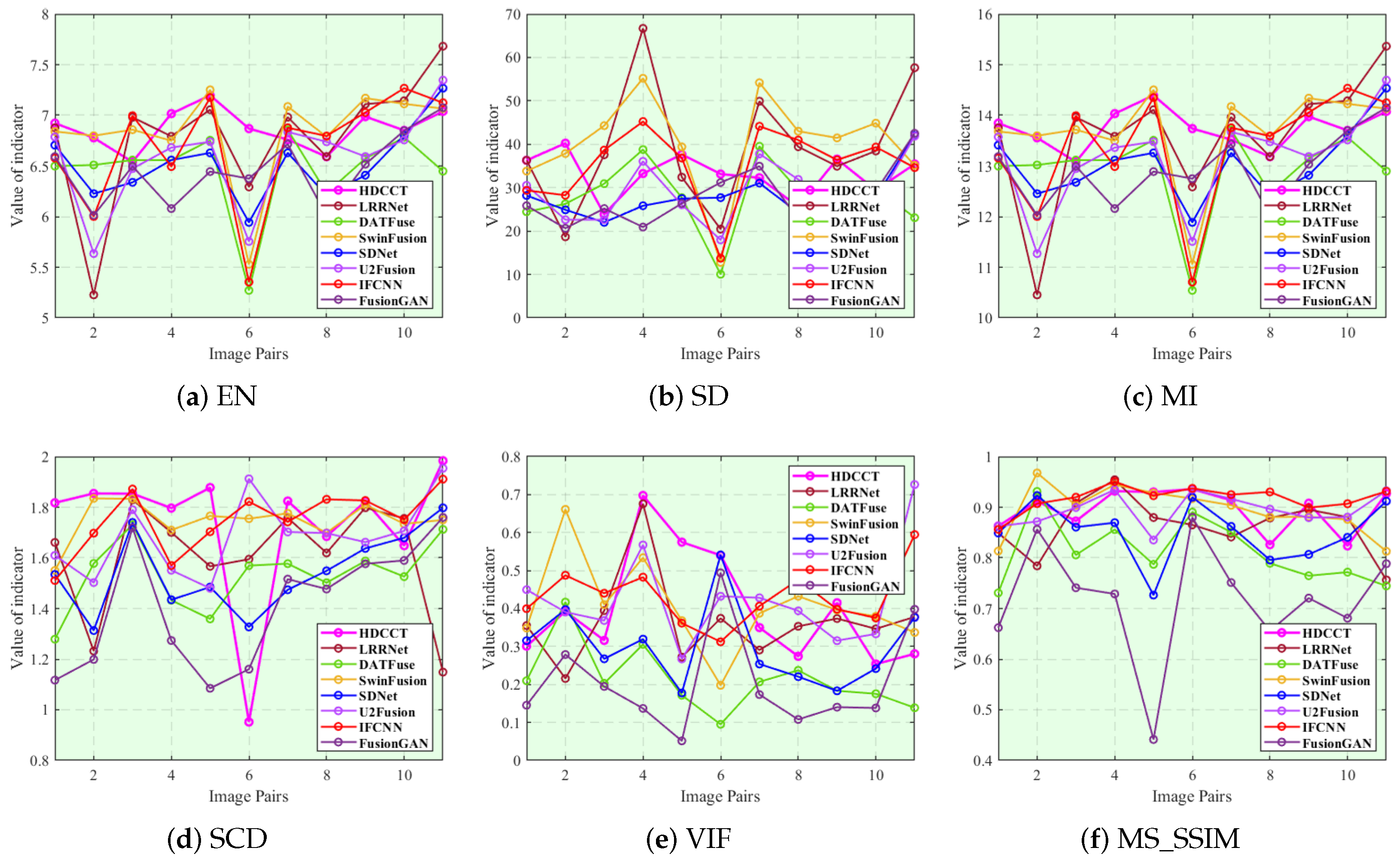
  • Entropy (EN). EN represents the amount of information contained in the image. A higher value of EN represents more information learned from the input images of the fused images. Assuming that n represents the grayscale level and P i is the grayscale probability distribution, then the expression for EN is
    E N = i = 0 n P i l o g 2 P i
  • Standard deviation (SD). SD is used to calculate how spread out the mean of the fused images is. It depicts the dispersion of image information and describes the visual effect on human attention. The larger the SD, the better the visual contrast for the fused images. Let μ represent the mean of the fused image, G i , j represent the grayscale value of each point, and { M , N } represent the width and height of the fused image, respectively; then, the formula of SD is
    S D = i = 1 M j = 1 N ( G ( i , j ) μ ) 2
  • Mutual information (MI). MI represents the information obtained from the input images for image fusion evaluation. The MI evaluation is general, since no assumptions are made on the nature of the relationship between image intensities in the input images. A higher MI value indicates that the fused image has extracted more information from the source image. The expression of MI is M I = M I I , F + M I V , F , in which M I I , F and M I V , F represent the information of transferring two input images to the fused image. Let H I ( i ) , H V ( v ) , and H F ( f ) represent the edge histograms of infrared image, visible image and fused image, and H I , F ( i , f ) , H V , F ( v , f ) represents the joint histogram of input image, and fused image; then, M I I , F and M I V , F can be expressed as
    M I I , F = i , f H I , F ( i , f ) l o g H I , F ( i , f ) H I ( i ) H F ( f ) M I V , F = v , f H V , F ( v , f ) l o g H V , F ( v , f ) H V ( v ) H F ( f )
  • Sum of the correlations of differences (SCD). SCD quantifies the information transferred from input images to fused images. It evaluates the merged images by summing the correlation values. The greater the SCD, the better the quality of the fused images. Assuming that D I , F and D V , F represent the differences between the input infrared/visible image and the fused image, respectively, the expression of SCD can be written as S C D = r ( I , D I , F ) + r ( V , D V , F ) , in which r ( X , D ) is expressed as
    r ( X , D ) = i = 1 M j = 1 N ( X ( i , j ) X ¯ ( D ( i , j ) μ ) ) i = 1 M j = 1 N ( X ( i , j ) X ¯ ) 2 i = 1 M j = 1 N ( D ( i , j ) μ ) 2
  • Visual information fidelity (VIF). VIF describes the quality of a fused image produced by the human visual system at multi-resolutions. Let C represent the random vector in the original image and S represent the forward scalar factor. The VIF between original image X and fused image F can be expressed as
    V I F = j s u b b a n d s I ( C N , j ; F N , j | S N , j ) j s u b b a n d s I ( C N , j ; X N , j | S N , j )
  • Multi-scale structural similarity (MS_SSIM). SSIM is a metric that assesses the similarity of two images by taking into consideration brightness, contrast, and structure. MS_SSIM is a multi-scale version of SSIM that captures more detailed information from images. We assume that l m represents the brightness similarity at the m-th scale, c j and s j represent the contrast and structural similarity at the j-th scale, and α , β , and γ are parameters used to balance the components. The MS_SSIM between original image X and fused image F can be represented as
    M S _ S S I M ( X , F ) = [ l m ( X , F ) ] α m × j = 1 m [ c j ( X , F ) ] β j × [ s j ( X , F ) ] γ j
These objective and subjective evaluation metrics are applied for judging the fusion results based on detailed information, human visual results, edge information, gradient, and variance. Multiple angles are used to guarantee the comparison of fusion outcomes.

4.2. Experiment on TNO Image Fusion

The experimental results for visible and infrared image fusion are tested on the TNO dataset with the gray images through numerical and quality comparisons.
For the combination of the global and local features with the CNN and transformer architecture, the fusion results integrate multiple-feature information to obtain better visualization results. Overall, the proposed method produces a more recognizable result, and the picture is more precise and more comfortable for human eyes. The visual results are represented in Figure 4. Compared with the related works, the proposed method has three improvements. Firstly, it can extract rich detailed information and global information such as texture, shape, and color from the visible images. Secondly, the thermal objects in the infrared image are maintained more completely to give a clearer outline to distinguish them from the background. Thirdly, the global information supplemented with the local information makes the fusion images more uniform and natural.
Table 1 shows the quantitative comparisons with the related works. As shown in Table 1, for the evaluation metrics EN, MI, and SCD, the proposed method outperforms other related works, as it can achieve an EN of 6.9004 and an MI of 13.8007 , showing a clear margin compared with the related works in global and local feature extraction ability. In addition, the proposed HDCCT framework obtains 1.7654 in SCD, accomplishing better performance than U2Fusion ( 1.6855 ) and IFCNN ( 1.7401 ). In the parameters of EN, MI, and VIF, the proposed HDCCT framework has slight advantages compared with the relevant works. Moreover, the performance of the proposed HDCCT framework on the evaluation metric MS_SSIM is also relatively satisfactory. Thus, HDCCT has the remarkable ability to extract detailed feature information, color information, and gradient information from the infrared and visible images. The qualitative comparison is detailed in Figure 5, which displays the specific image fusion outcomes on the infrared and visible image fusion datasets. Substantively, the suggested method performs satisfactorily in evaluation results for qualitative and quantitative comparisons, indicating that it is more competitive than comparable studies on the fusion results for visible and infrared images.

4.3. Experiment on RoadScene Image Fusion

The experiments on RoadScene are based on numerical and quality comparisons.
The experimental results of complex scene images are tested on the RoadScene dataset, which shows the intuitive fusion results in open situations under different lighting conditions, including both human and vehicle information. The experimental results, which can be seen in Figure 6, indicate that the CNN-based method, U2Fusion, loses the information of the visible images. Moreover, the DATFuse method loses the detailed features from the infrared images, which has apparent differences from these images. The GAN-based fusion method, FusionGAN, extracts rich thermal features from the infrared image and maintains the detailed texture features from the visible image. SDNet obtains the edge information with high homogenization for its global feature extraction ability. The proposed method combines local and global information, avoiding the results of inhomogeneity and the loss of detailed information. The proposed HDCCT framework achieves great visualization results in complex image fusion on the RoadScene dataset.
In Table 2, HDCCT is compared with the related works on six evaluation metrics on the 64 test image pairs from various complex situations in the RoadScene dataset. Six assessment metrics are applied to examine the experimental results of HDCCT. According to Table 2, the proposed HDCCT method is capable of achieving an SD of 49.6979 and an EN of 1.8809 , showing a clear margin compared with the related works in the ability of performing local and global feature extraction. The proposed method achieves 14.6808 in MI, achieving better performance than DATFuse ( 1.6408 ) and SwinFusion ( 1.3573 ) with the transformer network. In the parameters of EN and MS_SSIM, the proposed method has slight advantages compared with the relevant methods. Figure 7 illustrates the details of the qualitative comparison, which displays the specific image fusion results on the RoadScene dataset. Although the proposed HDCCT performs slightly worse than relevant methods on some single images, the overall average is still greater than the comparison methods on the six evaluation metrics. The proposed HDCCT method performs effectively in terms of texture and edge information evaluation results for both local and global information extraction. The qualitative and quantitative comparisons show that HDCCT outperforms the related works on the RoadScene dataset for complex situations.

4.4. Ablation Experiments

To assess the effectiveness of the proposed CNN and transformer combination architecture, the separate branches of the proposed network are tested. The TNO and RoadScene datasets are utilized for evaluation. The ablation studies are tested with the six metrics for the evaluation. Table 3 shows that the framework with pure CNN blocks achieves 6.7951 in EN, 36.5268 in SD, and 0.8096 in MS_SSIM, which are worse than the results obtained with the combination of the CNN and transformer architectures, i.e., 6.9004 in EN, 13.8007 in SD, and 0.9017 in MS_SSIM. The framework with pure transformer blocks is more competitive than the pure CNN transformer, with 6.8935 in EN, 36.6960 in SD, and 13.4796 in MS_SSIM, but still worse than the proposed combination architecture. The other three evaluation metrics, MI, SCD, and VIF, also showed similar results. The experimental results indicate that the hybrid CNN–transformer framework is more effective in expressing visible infrared features more significantly. The qualitative comparisons of the ablation study for the two blocks are displayed in Figure 8.
Moreover, the RoadScene dataset for complex multi-modal image fusion is used to test HDCCT. The proposed HDCCT method achieves an MI of 14.0617 , an SCD of 1.8809 , and a VIF of 0.4674 , showing better performance than the pure CNN or transformer method, as shown in Table 4. According to the experimental results, the CNN–transformer architecture performs better than the separate CNN blocks and the separate transformer blocks, showing the validity and rationality of HDCCT. The fusion image considered is a complex scene of people, cars, and buildings, as shown in Figure 9.
In addition, according to Table 5, the proposed method with the loss functions L s s i m and L m s e shows the best performance in EN, MI, SCD, VIF, and MS_SSIM, performing better than the single local loss function or the global loss function. Moreover, the qualitative comparisons of the ablation study on the loss functions are illustrated in Figure 10.

5. Conclusions

This paper offers a non-local multi-modal image fusion method that utilizes a hybrid densely connected CNN and transformer structure called HDCCT. The CNN blocks with the local information and the transformer with the global information are combined to extract the features. Moreover, the encoder–decoder architectures are used for image fusion, the CNN blocks, and the transformer blocks. The optimizer combines the local loss and the global loss, which further combines the features. The introduction of SSIM loss and MSE loss preserves the global and local information of features. HDCCT is tested in infrared and visible image fusion through visualization images and six evaluation metrics. The proposed HDCCT method achieves 0.0014 in EN, 0.0027 in MI, and 0.0185 in SCD in infrared and visible image fusion on the TNO dataset. For image fusion on the RoadScene dataset, the proposed HDCCT method achieves SD in 2.5891 and 0.0184 in SCD. The quantitative and qualitative comparisons show that HDCCT outperforms relevant works.
In future research, to expand the field of applications of the proposed HDCCT framework, we plan to improve the capacity of MRI-PIE and other multi-modal image fusion types. In addition, the image fusion performance of the proposed HDCCT method will be enhanced under various complex conditions, such as lighting, blur, etc., to improve the robustness and efficiency of HDCCT.

Author Contributions

All authors made contributions to this study, and the specific contributions of each author were as follows: X.L.: Methodology and Writing—original draft; H.H.: Methodology and Writing—review and editing; J.S.: Methodology and Writing—original draft. All authors have read and agreed to the published version of the manuscript.

Funding

This research received no external funding.

Data Availability Statement

RoadScene dataset, accessed on 7 August 2020 (https://github.com/hanna-xu/RoadScene); TNO dataset, accessed on 15 October 2022 (https://figshare.com/articles/dataset/TNO_Image_Fusion_Dataset/1008029).

Conflicts of Interest

Author Jin Shi was employed by CRSC Research and Design Institute Group Co., Ltd. The remaining authors declare that the research was conducted in the absence of any commercial or financial relationships that could be construed as a potential conflict of interest.

References

  1. Li, S.; Kang, X.; Fang, L.; Hu, J.; Yin, H. Pixel-level image fusion: A survey of the state of the art. Inf. Fusion 2017, 33, 100–112. [Google Scholar] [CrossRef]
  2. Kumar, P.; Mittal, A.; Kumar, P. Fusion of thermal infrared and visible spectrum video for robust surveillance. In Proceedings of the Computer Vision, Graphics and Image Processing: 5th Indian Conference, ICVGIP 2006, Madurai, India, 13–16 December 2006; Springer: Berlin/Heidelberg, Germany, 2006; pp. 528–539. [Google Scholar]
  3. Eslami, M.; Mohammadzadeh, A. Developing a spectral-based strategy for urban object detection from airborne hyperspectral TIR and visible data. IEEE J. Sel. Top. Appl. Earth Obs. Remote Sens. 2016, 9, 1808–1816. [Google Scholar] [CrossRef]
  4. Ma, J.; Ma, Y.; Li, C. Infrared and visible image fusion methods and applications: A survey. Inf. Fusion 2019, 45, 153–178. [Google Scholar] [CrossRef]
  5. Zhang, H.; Le, Z.; Shao, Z.; Xu, H.; Ma, J. MFF-GAN: An unsupervised generative adversarial network with adaptive and gradient joint constraints for multi-focus image fusion. Inf. Fusion 2021, 66, 40–53. [Google Scholar] [CrossRef]
  6. Hu, H.M.; Wu, J.; Li, B.; Guo, Q.; Zheng, J. An adaptive fusion algorithm for visible and infrared videos based on entropy and the cumulative distribution of gray levels. IEEE Trans. Multimed. 2017, 19, 2706–2719. [Google Scholar] [CrossRef]
  7. Xiang, T.; Yan, L.; Gao, R. A fusion algorithm for infrared and visible images based on adaptive dual-channel unit-linking PCNN in NSCT domain. Infrared Phys. Technol. 2015, 69, 53–61. [Google Scholar] [CrossRef]
  8. Bin, Y.; Chao, Y.; Guoyu, H. Efficient image fusion with approximate sparse representation. Int. J. Wavelets Multiresolut. Inf. Process. 2016, 14, 1650024. [Google Scholar] [CrossRef]
  9. Naidu, V. Hybrid DDCT-PCA based multi sensor image fusion. J. Opt. 2014, 43, 48–61. [Google Scholar] [CrossRef]
  10. Li, H.; Wu, X.J. DenseFuse: A fusion approach to infrared and visible images. IEEE Trans. Image Process. 2018, 28, 2614–2623. [Google Scholar] [CrossRef]
  11. Liu, Y.; Miao, C.; Ji, J.; Li, X. MMF: A Multi-scale MobileNet based fusion method for infrared and visible image. Infrared Phys. Technol. 2021, 119, 103894. [Google Scholar] [CrossRef]
  12. Li, Y.; Yang, H.; Wang, J.; Zhang, C.; Liu, Z.; Chen, H. An image fusion method based on special residual network and efficient channel attention. Electronics 2022, 11, 3140. [Google Scholar] [CrossRef]
  13. Fu, Q.; Fu, H.; Wu, Y. Infrared and Visible Image Fusion Based on Mask and Cross-Dynamic Fusion. Electronics 2023, 12, 4342. [Google Scholar] [CrossRef]
  14. Zhang, Y.; Zhai, B.; Wang, G.; Lin, J. Pedestrian Detection Method Based on Two-Stage Fusion of Visible Light Image and Thermal Infrared Image. Electronics 2023, 12, 3171. [Google Scholar] [CrossRef]
  15. Xu, H.; Ma, J.; Jiang, J.; Guo, X.; Ling, H. U2Fusion: A unified unsupervised image fusion network. IEEE Trans. Pattern Anal. Mach. Intell. 2022, 44, 502–518. [Google Scholar] [CrossRef] [PubMed]
  16. Li, H.; Wu, X.J.; Kittler, J. RFN-Nest: An end-to-end residual fusion network for infrared and visible images. Inf. Fusion 2021, 73, 72–86. [Google Scholar] [CrossRef]
  17. Gao, Y.; Ma, S.; Liu, J. DCDR-GAN: A densely connected disentangled representation generative adversarial network for infrared and visible image fusion. IEEE Trans. Circuits Syst. Video Technol. 2023, 33, 549–561. [Google Scholar] [CrossRef]
  18. Ma, J.; Yu, W.; Liang, P.; Li, C.; Jiang, J. FusionGAN: A generative adversarial network for infrared and visible image fusion. Inf. Fusion 2019, 48, 11–26. [Google Scholar] [CrossRef]
  19. Ma, J.; Xu, H.; Jiang, J.; Mei, X.; Zhang, X.P. DDcGAN: A dual-discriminator conditional generative adversarial network for multi-resolution image fusion. IEEE Trans. Image Process. 2020, 29, 4980–4995. [Google Scholar] [CrossRef]
  20. Gao, Y.; Ma, S.; Liu, J.; Xiu, X. Fusion-UDCGAN: Multifocus image fusion via a U-type densely connected generation adversarial network. IEEE Trans. Instrum. Meas. 2022, 71, 5008013. [Google Scholar] [CrossRef]
  21. Xu, H.; Ma, J.; Zhang, X.P. MEF-GAN: Multi-exposure image fusion via generative adversarial networks. IEEE Trans. Image Process. 2020, 29, 7203–7216. [Google Scholar] [CrossRef]
  22. Dosovitskiy, A.; Beyer, L.; Kolesnikov, A.; Weissenborn, D.; Zhai, X.; Unterthiner, T.; Dehghani, M.; Minderer, M.; Heigold, G.; Gelly, S.; et al. An image is worth 16 × 16 words: Transformers for image recognition at scale. arXiv 2020, arXiv:2010.11929. [Google Scholar]
  23. Wang, H.; Ji, Y.; Song, K.; Sun, M.; Lv, P.; Zhang, T. ViT-P: Classification of genitourinary syndrome of menopause from OCT images based on vision transformer models. IEEE Trans. Instrum. Meas. 2021, 70, 1–14. [Google Scholar] [CrossRef]
  24. Wu, B.; Xu, C.; Dai, X.; Wan, A.; Zhang, P.; Yan, Z.; Tomizuka, M.; Gonzalez, J.; Keutzer, K.; Vajda, P. Visual transformers: Token-based image representation and processing for computer vision. arXiv 2020, arXiv:2006.03677. [Google Scholar]
  25. Tang, W.; He, F.; Liu, Y.; Duan, Y.; Si, T. DATFuse: Infrared and visible image fusion via dual attention transformer. IEEE Trans. Circuits Syst. Video Technol. 2023, 33, 3159–3172. [Google Scholar] [CrossRef]
  26. Vs, V.; Valanarasu, J.M.J.; Oza, P.; Patel, V.M. Image fusion transformer. In Proceedings of the 2022 IEEE International Conference on Image Processing (ICIP), Bordeaux, France, 16–19 October 2022; IEEE: Piscataway, NJ, USA, 2022; pp. 3566–3570. [Google Scholar]
  27. Jin, X.; Xi, X.; Zhou, D.; Ren, X.; Yang, J.; Jiang, Q. An unsupervised multi-focus image fusion method based on Transformer and U-Net. IET Image Process. 2023, 17, 733–746. [Google Scholar] [CrossRef]
  28. Yuan, Y.; Wu, J.; Jing, Z.; Leung, H.; Pan, H. Multimodal image fusion based on hybrid CNN-transformer and non-local cross-modal attention. arXiv 2022, arXiv:2210.09847. [Google Scholar]
  29. Ram Prabhakar, K.; Sai Srikar, V.; Venkatesh Babu, R. Deepfuse: A deep unsupervised approach for exposure fusion with extreme exposure image pairs. In Proceedings of the IEEE International Conference on Computer Vision, Venice, Italy, 22–29 October 2017; pp. 4714–4722. [Google Scholar]
  30. Li, H.; Wu, X.J.; Durrani, T. NestFuse: An infrared and visible image fusion architecture based on nest connection and spatial/channel attention models. IEEE Trans. Instrum. Meas. 2020, 69, 9645–9656. [Google Scholar] [CrossRef]
  31. Vaswani, A.; Shazeer, N.; Parmar, N.; Uszkoreit, J.; Jones, L.; Gomez, A.N.; Kaiser, Ł.; Polosukhin, I. Attention is all you need. Adv. Neural Inf. Process. Syst. 2017, 31, 5998–6008. [Google Scholar]
  32. Xiao, T.; Singh, M.; Mintun, E.; Darrell, T.; Dollár, P.; Girshick, R. Early convolutions help transformers see better. Adv. Neural Inf. Process. Syst. 2021, 34, 30392–30400. [Google Scholar]
  33. Peng, Z.; Huang, W.; Gu, S.; Xie, L.; Wang, Y.; Jiao, J.; Ye, Q. Conformer: Local features coupling global representations for visual recognition. In Proceedings of the IEEE/CVF International Conference on Computer Vision, Montreal, BC, Canada, 11–17 October 2021; pp. 367–376. [Google Scholar]
  34. Qu, L.; Liu, S.; Wang, M.; Song, Z. TransMEF: A transformer-based multi-exposure image fusion framework using self-supervised multi-task learning. Proc. AAAI Conf. Artif. Intell. 2022, 36, 2126–2134. [Google Scholar] [CrossRef]
  35. Dogra, A.; Goyal, B.; Agrawal, S. From multi-scale decomposition to non-multi-scale decomposition methods: A comprehensive survey of image fusion techniques and its applications. IEEE Access 2017, 5, 16040–16067. [Google Scholar] [CrossRef]
  36. Li, S.; Yin, H.; Fang, L. Group-sparse representation with dictionary learning for medical image denoising and fusion. IEEE Trans. Biomed. Eng. 2012, 59, 3450–3459. [Google Scholar] [CrossRef] [PubMed]
  37. Wang, J.; Peng, J.; Feng, X.; He, G.; Fan, J. Fusion method for infrared and visible images by using non-negative sparse representation. Infrared Phys. Technol. 2014, 67, 477–489. [Google Scholar] [CrossRef]
  38. Zhao, J.; Chen, Y.; Feng, H.; Xu, Z.; Li, Q. Infrared image enhancement through saliency feature analysis based on multi-scale decomposition. Infrared Phys. Technol. 2014, 62, 86–93. [Google Scholar] [CrossRef]
  39. Lu, W.; Lan, C.; Niu, C.; Liu, W.; Lyu, L.; Shi, Q.; Wang, S. A CNN-transformer hybrid model based on CSW in transformer for UAV image object detection. IEEE J. Sel. Top. Appl. Earth Obs. Remote Sens. 2023, 16, 1211–1231. [Google Scholar] [CrossRef]
  40. Yu, Z.; Lee, F.; Chen, Q. HCT-net: Hybrid CNN-transformer model based on a neural architecture search network for medical image segmentation. Appl. Intell. 2023, 53, 19990–20006. [Google Scholar] [CrossRef]
  41. Nie, Y.; Sommella, P.; Carratù, M.; O’Nils, M.; Lundgren, J. A deep cnn transformer hybrid model for skin lesion classification of dermoscopic images using focal loss. Diagnostics 2022, 13, 72. [Google Scholar] [CrossRef]
  42. Wang, Z.; Simoncelli, E.P.; Bovik, A.C. Multiscale structural similarity for image quality assessment. In Proceedings of the Thrity-Seventh Asilomar Conference on Signals, Systems & Computers, Pacific Grove, CA, USA, 9–12 November 2003; IEEE: Piscataway, NJ, USA, 2003; Volume 2, pp. 1398–1402. [Google Scholar]
  43. Christoffersen, P.; Jacobs, K. The importance of the loss function in option valuation. J. Financ. Econ. 2004, 72, 291–318. [Google Scholar] [CrossRef]
  44. Zhang, Y.; Liu, Y.; Sun, P.; Yan, H.; Zhao, X.; Zhang, L. IFCNN: A general image fusion framework based on convolutional neural network. Inf. Fusion 2020, 54, 99–118. [Google Scholar] [CrossRef]
  45. Zhang, H.; Ma, J. SDNet: A versatile squeeze-and-decomposition network for real-time image fusion. Int. J. Comput. Vis. 2021, 129, 2761–2785. [Google Scholar] [CrossRef]
  46. Ma, J.; Tang, L.; Fan, F.; Huang, J.; Mei, X.; Ma, Y. SwinFusion: Cross-domain long-range learning for general image fusion via swin transformer. IEEE/CAA J. Autom. Sin. 2022, 9, 1200–1217. [Google Scholar] [CrossRef]
  47. Li, H.; Xu, T.; Wu, X.J.; Lu, J.; Kittler, J. Lrrnet: A novel representation learning guided fusion network for infrared and visible images. IEEE Trans. Pattern Anal. Mach. Intell. 2023, 45, 11040–11052. [Google Scholar] [CrossRef]
  48. Lin, T.Y.; Maire, M.; Belongie, S.; Hays, J.; Perona, P.; Ramanan, D.; Dollár, P.; Zitnick, C.L. Microsoft coco: Common objects in context. In Proceedings of the Computer Vision–ECCV 2014: 13th European Conference, Zurich, Switzerland, 6–12 September 2014; Part V 13. Springer: Cham, Switzerland, 2014; pp. 740–755. [Google Scholar]
  49. Roberts, J.W.; Van Aardt, J.A.; Ahmed, F.B. Assessment of image fusion procedures using entropy, image quality, and multispectral classification. J. Appl. Remote Sens. 2008, 2, 023522. [Google Scholar]
  50. Eskicioglu, A.M.; Fisher, P.S. Image quality measures and their performance. IEEE Trans. Commun. 1995, 43, 2959–2965. [Google Scholar] [CrossRef]
  51. Qu, G.; Zhang, D.; Yan, P. Information measure for performance of image fusion. Electron. Lett. 2002, 38, 1. [Google Scholar] [CrossRef]
  52. Aslantas, V.; Bendes, E. A new image quality metric for image fusion: The sum of the correlations of differences. Aeu-Int. J. Electron. Commun. 2015, 69, 1890–1896. [Google Scholar] [CrossRef]
  53. Han, Y.; Cai, Y.; Cao, Y.; Xu, X. A new image fusion performance metric based on visual information fidelity. Inf. Fusion 2013, 14, 127–135. [Google Scholar] [CrossRef]
  54. Wang, Z.; Bovik, A.C.; Sheikh, H.R.; Simoncelli, E.P. Image quality assessment: From error visibility to structural similarity. IEEE Trans. Image Process. 2004, 13, 600–612. [Google Scholar] [CrossRef]
Figure 1. The architecture of the proposed HDCCT framework.
Electronics 13 03470 g001
Figure 2. The architecture of the CNN blocks.
Electronics 13 03470 g002
Figure 3. The architecture of the transformer blocks.
Electronics 13 03470 g003
Figure 4. Image results of image fusion experiments on the TNO dataset.
Electronics 13 03470 g004
Figure 5. A comparison of six evaluation metrics obtained by randomly selecting ten image pairs on the TNO dataset.
Electronics 13 03470 g005
Figure 6. Image results of image fusion experiments on the RoadScene dataset.
Electronics 13 03470 g006
Figure 7. A comparison of six evaluation metrics obtained by randomly selecting ten image pairs on the RoadScene dataset.
Electronics 13 03470 g007
Figure 8. Image results of ablation experiments on the TNO dataset.
Electronics 13 03470 g008
Figure 9. Image results of ablation experiments on the RoadScene dataset.
Electronics 13 03470 g009
Figure 10. Image results of loss function ablation experiments on the RoadScene dataset.
Electronics 13 03470 g010
Table 1. The average of six evaluation metrics obtained from image fusion experiments on the TNO dataset. The up arrow (↑) indicates that higher values result in better performance. Bold and underline represent the highest and second highest values, respectively.
MethodEN ↑ SD ↑ MI ↑ SCD ↑ VIF ↑ MS_SSIM ↑
FusionGAN6.550830.646713.10151.37220.24810.7424
IFCNN6.800136.531613.60031.74010.46850.9082
U2Fusion6.707330.527813.41451.68550.45010.9010
SDNet6.693233.647613.38641.54910.36940.8742
SwinFusion6.899040.028113.79801.67750.39770.8762
DATFuse6.459727.620612.91931.49360.20360.8045
LRRNet6.762740.615713.52551.47730.36240.8319
HDCCT6.900436.790313.80071.76540.47120.9017
Table 2. The average of six evaluation metrics obtained from image fusion experiments on the RoadScene dataset. The up arrow (↑) indicates that higher values result in better performance. Bold and underline represent the highest and second highest values, respectively.
MethodEN ↑ SD ↑ MI ↑ SCD ↑ VIF ↑ MS_SSIM ↑
FusionGAN7.179241.730214.35841.42900.25500.7277
IFCNN7.079937.208214.15971.68530.41290.8969
U2Fusion6.899133.771413.79811.61810.38780.8980
SDNet7.355247.108814.71041.67780.39400.8937
SwinFusion6.661741.291113.32351.65440.36480.8033
DATFuse6.520029.020613.04001.40620.18730.7216
LRRNet7.127743.718414.25551.71670.37310.7829
HDCCT7.340449.697914.68081.88090.46740.9054
Table 3. The average of six evaluation metrics obtained from ablation experiments on the TNO dataset. The up arrow (↑) indicates that higher values result in better performance. The checkmark (✓) indicates that the module is used.
CNNTransformerEN ↑ SD ↑ MI ↑ SCD ↑VIF ↑MS_SSIM ↑
6.795136.526813.45821.72050.44860.8096
6.893536.696013.47961.74090.45800.8734
6.900436.790313.80071.76540.47120.9017
Table 4. The average of six evaluation metrics obtained from ablation experiments on the RoadScenedataset. The up arrow (↑) indicates that higher values result in better performance. The checkmark (✓) indicates that the module is used.
CNNTransformerEN ↑ SD ↑ MI ↑ SCD ↑VIF ↑MS_SSIM ↑
7.048537.108414.06171.65590.40730.8962
7.330049.220114.66011.88030.46270.9031
7.340449.697914.68081.88090.46740.9054
Table 5. The average of six evaluation metrics obtained from loss function ablation experiments on the RoadScene dataset. The up arrow (↑) indicates that higher values result in better performance. The checkmark (✓) indicates that the loss function is used.
L ssim L mse EN ↑ SD ↑MI ↑SCD ↑VIF ↑MS_SSIM ↑
7.303259.472014.60650.38430.31920.6274
7.312752.628114.62531.87790.48000.9040
7.340449.697914.68081.88090.46740.9054
Disclaimer/Publisher’s Note: The statements, opinions and data contained in all publications are solely those of the individual author(s) and contributor(s) and not of MDPI and/or the editor(s). MDPI and/or the editor(s) disclaim responsibility for any injury to people or property resulting from any ideas, methods, instructions or products referred to in the content.

