Article

Ambient Backscatter-Based User Cooperation for mmWave Wireless-Powered Communication Networks with Lens Antenna Arrays

1
College of Computer Science and Technology, Zhejiang University, Hangzhou 310058, China
2
School of Information and Electrical Engineering, Hangzhou City University, Hangzhou 310015, China
3
Zhejiang Engineering Research Center of Building’s Digital Carbon Neutral Technology, Hangzhou 310015, China
4
College of Information Science and Engineering, Jiaxing University, Jiaxing 314001, China
*
Author to whom correspondence should be addressed.
Electronics 2024, 13(17), 3485; https://doi.org/10.3390/electronics13173485
Submission received: 11 August 2024 / Revised: 30 August 2024 / Accepted: 1 September 2024 / Published: 2 September 2024

Abstract

:
With the rapid consumer adoption of mobile devices such as tablets and smart phones, tele-traffic has experienced a tremendous growth, making low-power technologies highly desirable for future communication networks. In this paper, we consider an ambient backscatter (AB)-based user cooperation (UC) scheme for mmWave wireless-powered communication networks (WPCNs) with lens antenna arrays. Firstly, we formulate an optimization problem to maximize the minimum rate of two users by jointly designing power and time allocation. Then, we introduce auxiliary variables and transform the original problem into a convex form. Finally, we propose an efficient algorithm to solve the transformed problem. Simulation results demonstrate that the proposed AB-based UC scheme outperforms the competing schemes, thus improving the fairness performance of throughput in WPCNs.

1. Introduction

1.1. Motivation

With the continuous evolution of wireless networks, sixth-generation communication (6G) is expected to realize ultrabroadband, ubiquitous connectivity, and integrated sensing and communication, which will enable many significant application scenarios such as internet of things (IoT), smart transportation, monitoring of the environment, and so on [1,2,3]. It is estimated that the number of global network terminals will hit 125 billion by 2030, and the number of IoT connections per cubic meter could reach up to 100 [4]. Limited by device size and deployment environment, some IoT devices are energy constrained. Therefore, future communication networks will benefit greatly from low-power technologies, not only by improving spectrum efficiency but also by being highly desirable.
In this regard, wireless energy transfer (WET), which can receive power wirelessly through radio-frequency (RF) transmission, has the potential to supply ample energy to wireless systems with limited power. Furthermore, the seamless integration of WET and wireless connectivity has become a popular area of research, known as wireless-powered communication networks [5,6]. A harvest-then-transmit (HTT) protocol is suggested in [7] for WPCNs, where users initially collect energy from RF signals sent by a hybrid access point (HAP) in the downlink (DL), and subsequently, send their information to the HAP in the uplink (UL). However, users located far from the HAP harvest much less energy than those close to it, yet they must consume more energy to transmit data back to the HAP, creating a ‘doubly near–far’ user unfairness problem. With consideration of the fairness issue, user cooperation is an effective approach, in which the user far from the HAP cooperates with their adjacent user to transmit signals to the HAP.
Several UC schemes for WPCNs have been developed based on different models [8,9,10]. Optimal energy beamforming and time assignment were designed by the authors in [8] to explore the performance limit of system information transmission with two single-antenna users and an HAP. The authors in [9] considered a reconfigurable intelligent surface (RIS)-assisted UC in a WPCN. Then, they collaboratively optimized the distribution of transmit time and power for both users, as well as the coefficients of the passive array for reflecting wireless energy and information signals in order to maximize the shared minimum throughput of the system. In [10], the authors collaboratively optimized the allocation of time, power, and energy beamforming vectors to maximize the energy efficiency (EE) in a scenario containing two UC users and a separated power station and information receiver.
One significant problem with current user collaboration schemes is the excessive overhead involved in exchanging information among users. Specifically, a new low-cost ambient backscatter communication (AmBC) technique [11] allows users to transmit information by passively backscattering environmental RF signals, thus achieving device battery conservation. Compared to the HTT mode, IoT devices operating in backscatter mode exhibit reduced power consumption [12]. In AmBC systems, a backscatter device (BD) utilizes ambient signals that are already modulated by surrounding RF sources such as Wi-Fi access points, TV towers, or cellular network base stations for communication [13]. The BD changes the backscattered signal by alternating between two modes: a mode for backscattering, when the BD antenna is short-circuited; and a mode for transmission, when the BD antenna is open-circuited. These modes are used to indicate bit ‘0’ and bit ‘1’. Typically, the backscatter receiver (BR) is equipped with an energy detector (ED) [14] to determine the received power levels of AmBC signals, and then, associate them with the corresponding transmitted signals from the BD. As a result, the AmBC system is efficient in terms of energy as it does not require active RF signal transmission, and it also makes efficient use of the spectrum by sharing it with ambient RF sources. Actually, except for ambient backscatter (AB), there are two types of backscatter modes: bistatic backscatter (BB), for which the RF emitter and BR can be separately deployed; and monostatic backscatter (MB), for which the RF emitter and BR are colocated [15]. The AB mode device communicates by modulating and reflecting ambient signals, eliminating the need for dedicated spectrum and energy unlike the other two types [16].
Nonetheless, ambient backscatter communication relies on the unpredictable nature of data traffic to generate the necessary excitation signal for IoT devices utilizing backscattering. As a result, WPCN systems should utilize energy-efficient technologies such as mmWave multiple-input multiple-output (MIMO) communication to provide active RF signals. MmWave MIMO has emerged as a crucial technology for future cellular networks due to the availability of abundant spectrum resources at higher frequencies and its high energy efficiency with beamforming. Furthermore, mmWave technology is suitable for various short-range wireless communication scenarios like IoT because of its short wavelength and wide frequency band.

1.2. Related Work

The combination of mmWave-based communication systems and WPCNs has garnered significant interest in recent research. In [17], the authors studied the WPT performance of the mmWave band with a typical low-power device. In comparison to lower frequencies, WPCN in mmWave bands has the capability to offer improved energy transfer coverage when using optimal parameters. Additionally, the efficiency of WPT in a massive mmWave WPCN was studied by the authors in [18], and simulation results showed that mmWave WPT outperformed WPCNs operating at lower frequencies. The authors in [19] introduced a more practical non-linear energy harvesting model in a massive mmWave WPCN system and analyzed the potential performance of WPT. The study in [20] examined the probability of beam outage and energy outage for a mmWave WPCN using a random energy beamforming scheme, while the arrangement of energy receivers was based on the homogeneous Poisson point process (HPPP). Then, the authors analyzed the optimal performance of a mmWave WPCN system. In [21], the authors jointly designed the transmit power, beamforming, and power split coefficient for the optimization of transmission performance of a mmWave-based WPCN with imperfect channel state information (CSI). By exploiting the advantages of multiple antennas, energy beamforming can be adopted to transfer energy signals to all users in a mmWave WPCN. Nevertheless, the traditional fully digital beamforming methods lead to excessive power usage and RF chain expenses. In [22], we equip an HAP with a discrete lens array (DLA) [23], which reduces the complexity and cost of the RF hardware as well as improving the power budget due to the lens’s energy-focusing capability [24]. A typical DLA mainly contains an electromagnetic lens and a corresponding antenna array, with elements located in the lens’s focal region. The lenses can execute variable phase shifts for incident signals at different points of the lens aperture to obtain an angle-dependent energy-focusing result [23]. The DLA can transform the traditional mmWave MIMO channels into beamspace channels equivalently with angle-dependent energy-focusing abilities. As the beamspace channels of mmWave MIMO systems are sparse, only a small quantity of beams are needed. In mmWave MIMO systems, each beam needs a single RF chain, so the DLA can reduce the cost of RF chains effectively. Furthermore, the phase shifters of the mmWave MIMO system are replaced by a switching network with DLA, which decreases the complexity and cost of the hardware. However, the UC scheme for user fairness issues with DLA needs to be further considered.

1.3. Our Contributions

Based on our previous work [22], in this paper, we consider an AB-based UC scheme in a mmWave WPCN with multiple antennas on the HAP. In order to ensure fairness for users, we initially establish an optimization problem aimed at maximizing the minimum rate of two users through the joint design of power and time allocation. To address this nonconvex issue, we introduce auxiliary variables and transform the original problem into a convex form. Subsequently, an efficient algorithm is proposed to solve the problem. Simulation results show that compared to traditional UC schemes using active communication, the passive AB-based UC scheme with DLA can effectively improve the throughput performance of energy-constrained devices in mmWave WPCNs. This particular scenario has not been previously explored.

1.4. Notation and Paper Organization

The remainder of this paper is structured as follows. Section 2 introduces the UC system model based on AB and formulates the optimization problem. The algorithm is proposed in Section 3. Our experimental results are analyzed in Section 4, and the paper concludes in Section 5.
Notation: In this document, the symbol a i j in lowercase represents the element at position ( i , j ) in matrix A . Bold uppercase and lowercase letters A and a represent a matrix and a vector, respectively. The symbols A T , A H , | | A | | 2 , and Tr ( A ) denote the transpose, conjugate transpose, Frobenius norm, and trace of matrix A , respectively. The symbol I K refers to the identity matrix of size K × K , while E { · } denotes an expectation operation.

2. System Model and Problem Formulation

We consider a mmWave WPCN with one HAP and two single-antenna users ( U 1 and U 2 ). The HAP is equipped with a DLA, which includes M t antennas and one RF chain. The network topology is depicted in Figure 1, and for simplicity, we assume that these three nodes are arranged in a linear configuration. The HAP has a fixed power supply, while the two users must harvest energy from the signals transmitted by the HAP during the DL WET phase. The harvested energy is stored in an energy buffer (e.g., rechargeable battery), after which the users transmit information during the UL wireless information transmission (WIT) phase.

2.1. Channel Model

We hypothesize that WET and WIT function within an identical frequency range, and there is channel reciprocity between the DL and UL. The beamspace channel matrix, H ˜ , is derived from the physical spatial MIMO channel:
H ˜ = [ h ˜ 1 , h ˜ 2 ] = [ Uh 1 , Uh 2 ] ,
where the matrix U C M t × M t represents the discrete Fourier transformation (DFT) corresponding to DLAs at the HAP, and h k C M t × 1 is the channel vector between the HAP and user k in the spatial domain. The DFT matrix U comprises of steering vectors for M t orthogonal beams distributed across the entire angular domain, i.e.,
U = [ a ( φ 1 ) , a ( φ 2 ) , , a ( φ M t ) ] H ,
where the spatial directions φ m are normalized as φ m = 1 M t ( m M t + 1 2 ) , where m = 1 , 2 , , M t . The corresponding array-steering vectors a ( φ m ) are defined as a ( φ m ) = 1 M t ( e j 2 π φ m i ) i I , with M t × 1 dimensions. Here, the index set of array elements is denoted by I = { i ( M t 1 ) / 2 | i = 0 , 1 , , M t 1 } .
In a typical multi-path setting, if we assume transmission, the channel can be expressed as
h k = β k ( 0 ) a ( ϕ k ( 0 ) ) + l = 1 L β k ( l ) a ( ϕ k ( l ) ) ,
where β k ( 0 ) a ( ϕ k ( 0 ) ) and β k ( l ) a ( ϕ k ( l ) ) represent the channel vectors for the direct line-of-sight (LoS) and the l-th non-line-of-sight (NLoS) paths between the HAP and user k, respectively. Additionally, β k ( 0 ) ( β k ( l ) ) denote the complex channel gains, while ϕ k ( 0 ) ( ϕ k ( l ) ) represent the corresponding spatial directions. For simplicity, we only consider azimuth angles of departure (AoD), assuming that the elevation AoD is zero due to practical validity when users are much higher than their height difference compared to the distance from the HAP. The extension to a 3D scenario is straightforward and does not affect the nature of the problem. We assume that the beamspace channel matrix H ˜ is perfectly estimated by the HAP [22,24,25].

2.2. The Protocol Description

As depicted in Figure 1, the system functions through four stages. During the initial phase, lasting τ 1 , the HAP sends out an energy signal with a constant power P 1 . The energy signal received by user k can be represented as
y u k ( 1 ) = P 1 h ˜ k H f t s 1 + n u k ,
in which s 1 , satisfying E { s 1 H s 1 } = 1 , is the transmitted signal; h ˜ k C M t × 1 is the beamspace channel vector between the HAP and user k; f t C M t × 1 is the beam selection vector with only one non-zero element 1; and n u k CN ( 0 , σ 0 2 ) is the additive zero-mean circular complex Gaussian noise at user k, where σ 0 2 denotes the noise variance.
The HAP transmits energy to all users using beam selection in order to enhance WET. We choose the beam with the highest magnitude [23] to maximize power transfer for each user. It is assumed that the energy harvested from noise n d k can be disregarded. Therefore, the anticipated energy harvested by user k can be represented as
E u k ( 1 ) = η P 1 τ 1 | h ˜ k H f t s 1 | 2 ,
where the energy-converting efficiency, 0 < η < 1 , is assumed fixed and equal for all users.
In the second phase, with τ 2 amount of time, U 1 harvests energy from an incident signal transmitted by the HAP, and also backscatters a different fraction of the incident signal to U 2 to transmit “0” or “1”. As a result, U 2 employs non-coherent detection methods such as the energy detector [11] to interpret the transmitted bit. When U 1 sends a “0”, only the energy signal from the HAP is received by U 2 :
y u 2 , 0 ( 2 ) = P 1 h ˜ 2 H f t s 2 + n u 2 ,
where s 2 , satisfying E { s 2 H s 2 } = 1 , is the transmitted signal. On the other hand, when U 1 transmits a bit “1”, U 2 receives a combination of signals from both the HAP and U 1 , i.e.,
y u 2 , 1 ( 2 ) = P 1 h ˜ 2 H f t s 2 + μ β 12 P 1 h ˜ 1 H f t s 2 + n u 2 ,
where μ is the signal attenuation coefficient due to the reflection at U 1 , and β 12 denotes the channel coefficient between U 1 and U 2 .
We apply a power splitting scheme in U 2 , i.e., the received RF signal is split into two parts, with a constant splitting factor γ [ 0 , 1 ] . Accordingly, the γ part of the RF signal power is harvested, and the remaining ( 1 γ ) part is used for information decoding (ID). The circuit of ID introduces an extra noise, n e CN ( 0 , σ 1 2 ) . We assume n e is independent of n u k , k = 1 , 2 . As a result, the signal at the ID receiver and energy decoder can be written as
y u 2 , I ( 2 ) = 1 γ y u 2 ( 2 ) + n e , y u 2 , E ( 2 ) = γ y u 2 ( 2 ) ,
where y u 2 ( 2 ) = y u 2 , 1 ( 2 ) when U 1 backscatters “1”, and y u 2 ( 2 ) = y u 2 , 0 ( 2 ) when U 1 transmits “0”. We assume that “0” and “1” are transmitted with equal probability without loss of generality. Then, we can obtain the harvested energy by U 2 , which is given by
E u 2 ( 2 ) = 1 2 η γ τ 2 ( E [ | y u 2 , 1 ( 2 ) | 2 ] + E [ | y u 2 , 0 ( 2 ) | 2 ] ) = 1 2 η γ P 1 τ 2 ( 2 | h ˜ 2 H f t s 2 | 2 + μ 2 β 12 2 | h ˜ 1 H f t s 2 | 2 ) .
Note that here we assume the signal backscattered from U 1 is uncorrelated with the signal received directly from the HAP due to the random modulation during the backscatter phase. Additionally, the battery level of U 1 remains constant because the energy usage from operating the backscatter transmitter is negligible compared to the energy harvested during this phase. We also assume a fixed backscattering data rate R b bps, and the sampling rate of the backscatter receiver at U 2 is N b R b , which means the receiver takes N b samples of each bit. We are able to calculate the probability of bit error (BER) P b when employing an optimal energy detector for decoding the received single-bit data [14]:
P b = 1 2 e r f c [ ( 1 γ ) P 1 μ 2 N b β 12 2 | h ˜ 1 H f t s | 2 4 ( ( 1 γ ) σ 0 2 + σ 1 2 ) ] .
The process of communication can be represented as a binary symmetric channel, with its capacity measured in bits per channel use, i.e.,
C b = 1 + P b log P b + ( 1 P b ) log ( 1 P b ) .
And the effective bit rate from U 1 to U 2 can be expressed as
R 12 ( 2 ) = C b R b τ 2 .
In the third phase, of duration τ 3 , U 1 transmits information to the HAP and U 2 simultaneously by exhausting the energy harvested in the first phase. The average transmit power of U 1 is given by
P 3 = E u 1 ( 1 ) / τ 3 = η P 1 τ 1 | h ˜ 1 H f t s 1 | 2 / τ 3 .
The received signal at the HAP and U 2 can be expressed as
y u 0 ( 3 ) = P 3 f r T h 1 s 3 + n u 0 , y u 2 ( 3 ) = β 12 P 3 s 3 + n u 2 ,
where f r T C 1 × M t is the beam selection vector which chooses the largest element of the UL channel h 1 , just like f t ; s 3 , satisfying E { | s 3 | 2 } = 1 , is the complex base-band signal of U 1 ; and n u 0 CN ( 0 , σ 0 2 ) denotes the receiver noise at the HAP.
In the last phase, U 2 first transmits U 1 ’s signal to the HAP with power P 41 and time τ 41 ; after that, U 2 transmits its own signal to the HAP with power P 42 and time τ 42 . We can acquire the total energy consumed by U 2 in the last phase constrained by the energy harvested in the first and second phases:
P 41 τ 41 + P 42 τ 42 E u 2 ( 1 ) + E u 2 ( 2 ) .
We also have a total time constraint of time allocations τ ( τ 1 , τ 2 , τ 3 , τ 41 , τ 42 ) :
τ 1 + τ 2 + τ 3 + τ 41 + τ 42 T ,
where T represents the length of time during which the channel remains unchanged. For simplicity, we set T = 1 . Then, the achievable rates of transmitting U 1 ’s signal from U 1 to U 2 and the HAP in the third phase, and from U 2 to the HAP in the last phase, can be written as
R 12 ( 3 ) = τ 3 log 2 1 + P 3 β 12 2 σ 0 2 ,
R 10 ( 3 ) = τ 3 log 2 1 + P 3 | f r T h 1 | 2 σ 0 2 ,
R 10 ( 4 ) = τ 41 log 2 1 + P 41 | f r T h 2 | 2 σ 0 2 .
Thus, the achievable rates of U 1 and U 2 within the duration T = 1 can be obtained [8]:
R 1 = min ( R 12 ( 2 ) + R 12 ( 3 ) , R 10 ( 3 ) + R 10 ( 4 ) ) ,
R 2 = τ 42 log 2 1 + P 42 | f r T h 2 | 2 σ 0 2 .

2.3. Problem Formulation

We optimize the power and time allocation of U 1 , U 2 , and the HAP under the max–min throughput criterion. This involves designing a joint optimization problem:
max P , τ min ( R 1 , R 2 )
s . t . τ 1 , τ 2 , τ 3 , τ 41 , τ 42 0 ,
P 41 , P 42 0 ,
( 13 ) , ( 15 ) , ( 16 ) ,
where P ( P 41 , P 42 ) . Note that when we set τ 2 = 0 , the original problem (19) reduces to the case of a conventional UC scheme without AB. Furthermore, if we set τ 2 = τ 41 = 0 , (19) reduces to a case of WPCN without UC, which means the far user U 1 does not cooperate with the near user U 2 to transmit its information to the HAP.

3. Problem Transformation

Problem (19) is nonconvex due to the multiplicative terms in constraint (15), so we introduce auxiliary variables V { V 1 , V 2 } , satisfying V 1 = P 41 τ 41 and V 2 = P 42 τ 42 , to deal with coupled variables { P 41 , τ 41 } and { P 42 , τ 42 } . Then, R 12 ( 3 ) and R 10 ( 3 ) in the original problem can be rewritten as functions of τ and { V 1 , V 2 } . In addition, as P 3 is defined in (13), R 10 ( 4 ) and R 2 can be re-expressed as functions of τ :
R 12 ( 3 ) = τ 3 log 2 1 + δ 1 τ 1 τ 3 , R 10 ( 3 ) = τ 3 log 2 1 + δ 2 τ 1 τ 3 , R 10 ( 4 ) = τ 41 log 2 1 + V 1 δ 3 τ 41 , R 2 = τ 42 log 2 1 + V 2 δ 3 τ 42 .
where
δ 1 = η P 1 β 12 2 | h ˜ 1 H f t s | 2 σ 0 2 , δ 2 = η P 1 | h ˜ 1 H f t s | 2 | f r T h 1 | 2 σ 0 2 , δ 3 = | f r T h 2 | 2 σ 0 2
are all constants. We also introduce an auxiliary variable R satisfying R min ( R 1 , R 2 ) . Then, we can transform the original problem (19) into an equivalent form expressed as
max V , τ R
s . t . R R 12 ( 2 ) + R 12 ( 3 ) ,
R R 10 ( 3 ) + R 10 ( 4 ) ,
R R 2 ,
V 1 + V 2 E u 2 ( 1 ) + E u 2 ( 2 ) ,
τ 1 + τ 2 + τ 3 + τ 41 + τ 42 1 ,
τ 1 , τ 2 , τ 3 , τ 41 , τ 42 0 ,
in which R 12 ( 3 ) , R 10 ( 3 ) , R 10 ( 4 ) , and R 2 are all concave functions. As E u 2 ( 1 ) and E u 2 ( 2 ) are affine functions of τ 1 , τ 2 , we can find that problem (22) is convex, which can be addressed with existing convex optimization tools and algorithms, e.g., the CVX tool [26] and the interior point method. Finally, when we obtain the solution of (22), the optimal solution of P can be obtained with P 41 = V 1 / τ 41 and P 42 = V 1 / τ 42 .

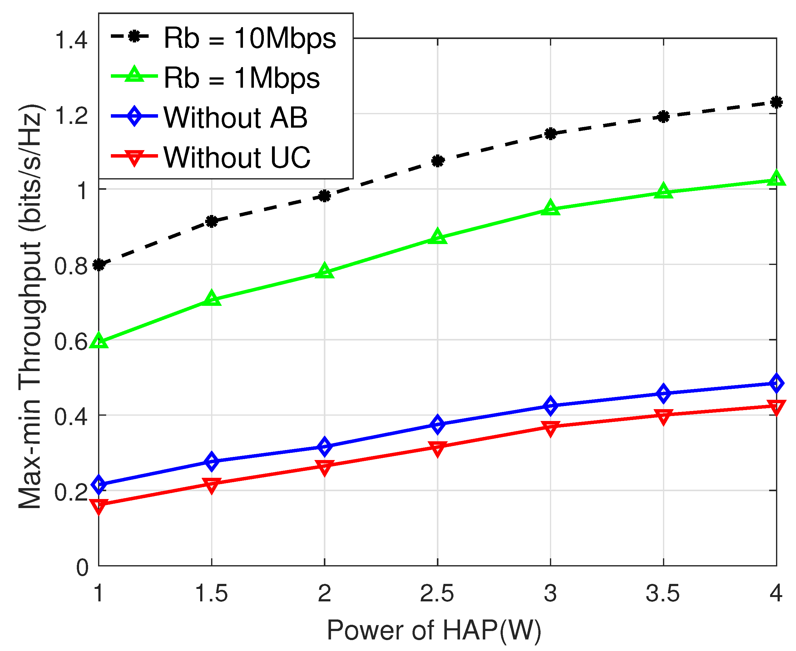
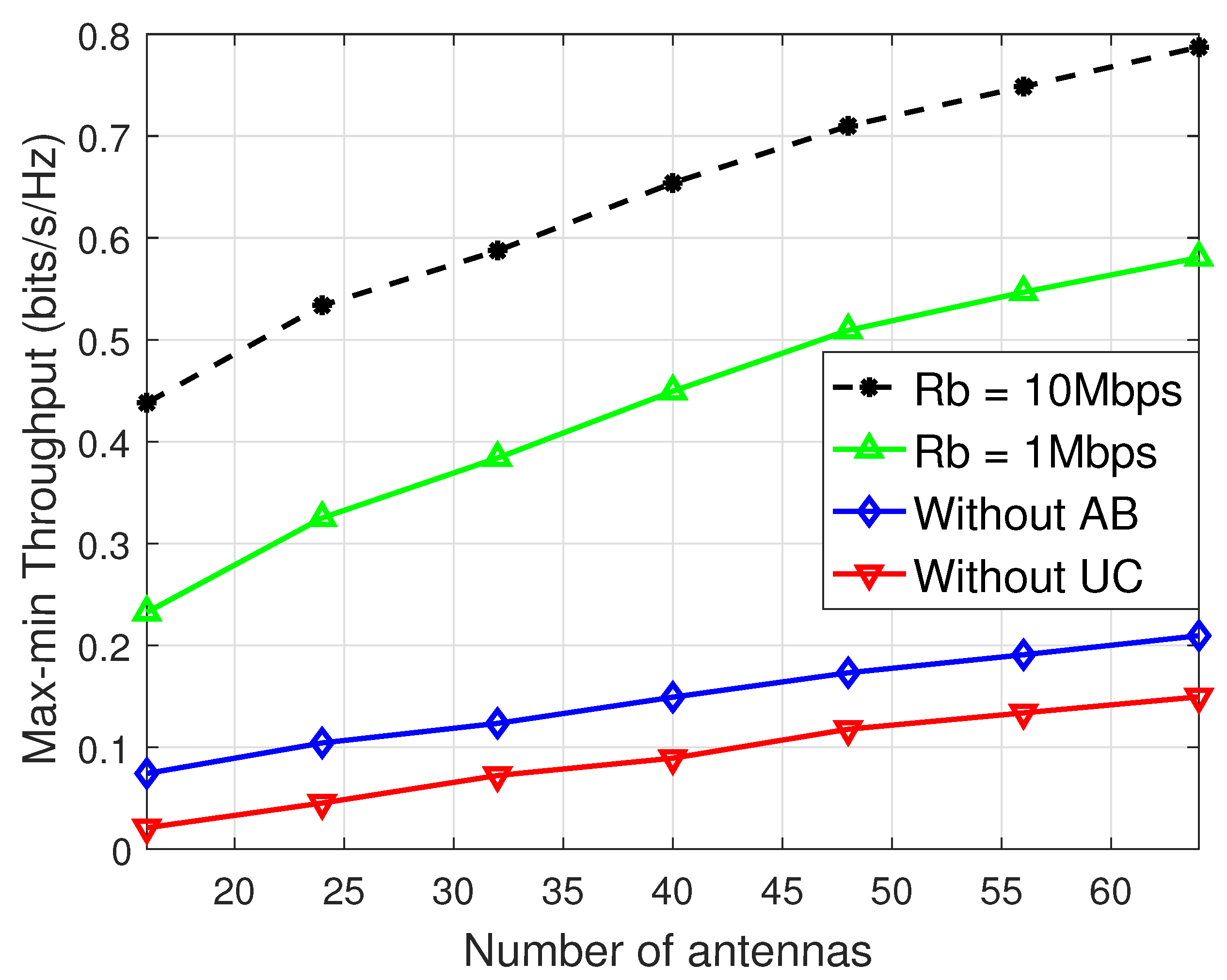
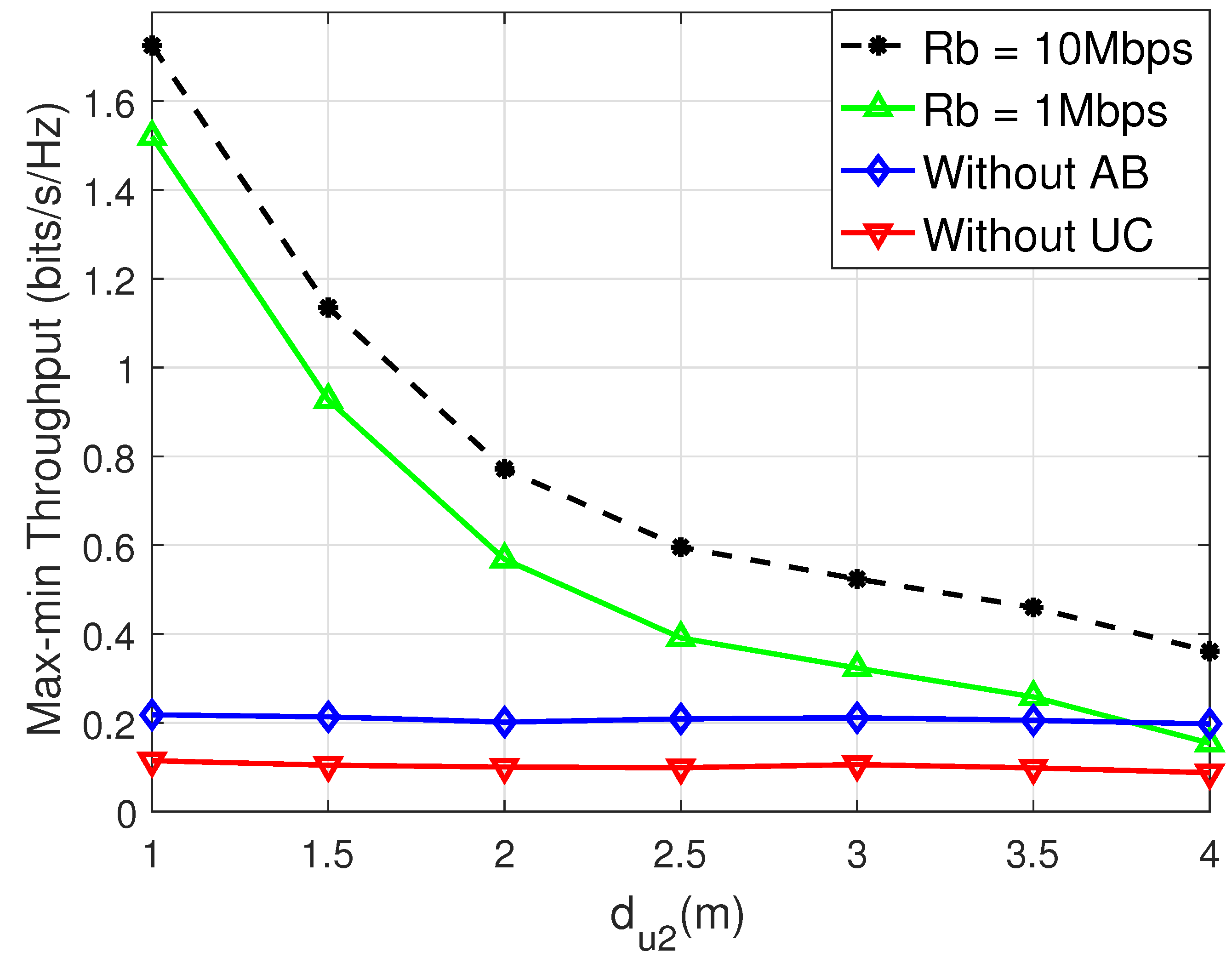
4. Simulation Results

In this section, We consider a mmWave WPCN consisting of one HAP and two single-antenna users. The system configuration is defined by the following choice of parameters: the HAP is equipped with a DLA, comprising M t = 64 antennas and one RF chain. A prototype lens antenna array has been fabricated, based on which the preliminary measurement results have verified the angle-dependent energy focusing capabilities of lens arrays [27]. The power of the HAP P 1 is set to 0 dBW. The noise power of all receivers σ 0 2 is set to −100 dBW, and the noise power of the ID circuit σ 1 2 is set to −100 dBW. The energy-converting efficiency η = 0.6 . The power splitting factor of U 2 is γ = 0.8 and the signal attenuation coefficient is μ = 0.8 [20]. We also choose two transmitting rates of AB for comparison, i.e., R b = 10 Mbps and R b = 1 Mbps, and the corresponding sample rate of AB is six times that of R b , i.e., N b = 6 . The channel model parameters are set as [28] (1) one LoS link and L = 2 NLoS links; (2) ϕ k ( 0 ) and ϕ k ( l ) obey the uniform distribution within [ 1 2 , 1 2 ] ; (3) the LOS channel gain ( β k ( 0 ) ) 2 = G ( c 4 π d u k f c ) 2 , where G = M t is the antenna power gain, c = 3 × 10 8 m/s is the speed of light, d u k is the distance between user k and the HAP, and f c = 30 GHz is the carrier frequency of the mmWave band. The channel gain between U 1 and U 2 is ( β 12 ( 0 ) ) 2 = G ( c 4 π d 12 f c ) 2 , where d 12 = d u 1 d u 2 is the distance between U 1 and U 2 . We set the NLOS channel gain β k ( l ) = 0.1 β k ( 0 ) .
In the rest of this section, we compare the max–min rate performance versus P 1 , M t , d u 1 , and d u 2 for different schemes, i.e., the AB-based UC schemes with R b = 10 Mbps and R b = 1 Mbps (shown as R b = 1 and R b = 10 in the simulation results, respectively), a UC scheme without AB (shown as “Without AB” in the simulation results), and a conventional scheme without UC (shown as “Without UC” in the simulation results). In Figure 2, we change the transmitting power of the HAP P 1 from 1 W to 4 W. We can observe that the performances of all schemes are improved with increasing transmitting power P 1 , and the proposed AB-based UC schemes have better performance than other competing schemes. The scheme with R b = 10 has a better performance than the scheme with R b = 1 , owing to the higher R b reducing the power consumption of information transmission between U 1 and U 2 more.
In Figure 3, we change the number of antennas at the HAP M t from 8 to 64. We can observe that the performances of all schemes are improved with an increasing number of antennas M t , benefiting from the energy capability of the lens array. Similarly, the proposed AB-based UC schemes have better performance than other competing schemes, which shows the AB technology can improve the performance of the UC system.
In Figure 4, we set P 1 = 4 W , M t = 64 , and d u 2 = 2 m, and change d u 1 from 4 m to 7 m. We find that the performance of all schemes decreases as d u 1 grows longer; this is because the channel between U 1 and HAP is attenuated more severely as d u 1 increases. Upon observation, it is evident that the efficiency of UC schemes utilizing AB declines at a slower rate compared to other schemes. This indicates that passive AB usage can effectively lower energy consumption, and consequently, enhance throughput performance. Therefore, the simulation results illustrate the benefits of implementing AB to enhance the throughput performance of UC schemes in WPCNs.
In Figure 5, we set P 1 = 4 W , M t = 64 , and d u 1 = 5 m, and change d u 2 from 1 m to 4 m. We can find that the performance of the scheme without UC hardly changes with d u 2 , as its performance is mainly limited by the weak channel between the HAP and the farther user U 1 . On the other hand, the performance of AB-based UC schemes increases as d u 2 grows shorter; this is because when d u 2 decreases, the distance between U 1 and U 2 increases, thus U 1 needs more energy to transmit actively to the helping U 2 , and the use of passive AB can effectively reduce the energy consumption, and thus, improve the throughput performance.

5. Conclusions

In this paper, we have considered an AB-based UC scheme in a mmWave WPCN with lens antenna arrays. In particular, to solve the ‘doubly near–far’ user unfairness problem, we have formulated an optimization problem to maximize the minimum rate of two users by jointly designing the power and time allocation of the HAP and users. After that, we have introduced auxiliary variables and transformed the original problem into a convex form. Then, we have proposed an efficient algorithm to solve the transformed problem. Furthermore, we have compared the max–min rate performance versus the transmission power of the HAP, the number of HAP antennas, and the distance between two users and the HAP for different schemes. The simulation results have demonstrated that the proposed AB-based UC scheme with DLA outperforms the competing schemes, thus improving the throughput fairness performance in the mmWave WPCN with lower costs for RF hardware and a lower power budget.

Author Contributions

Conceptualization: R.G. and R.Y.; methodology: R.G. and R.Y.; software: J.Y. and C.X.; investigation: R.G., G.W., and J.Y.; resources: R.G. and R.Y.; data curation: J.Y. and C.X.; writing—original draft preparation: R.G. and J.Y.; writing—review and editing: R.G. and R.Y.; visualization: R.G. and G.W.; funding acquisition: R.G. and R.Y. All authors have read and agreed to the published version of the manuscript.

Funding

This work was supported in part by the China Postdoctoral Science Foundation under Grant 2023M743063 and the Zhejiang Provincial Postdoctoral Scholarship under Grant ZJ2022107, in part by the National Natural Science Foundation of China under Grant 61771429, Grant 62302197 and Grant 62271438, Zhejiang Provincial Natural Science Foundation of China under Grant LQ23F020006.

Data Availability Statement

Dataset available on request from the authors.

Conflicts of Interest

The authors declare that there are no conflicts of interest regarding the publication of this paper.

References

  1. Latva-Aho, M.; Leppanen, K. Key Drivers and Research Challenges for 6G Ubiquitous Wireless Intelligence; University of Oulu: Oulu, Finland, 2019; White Paper 1; Available online: http://urn.fi/urn:isbn:9789526223544 (accessed on 9 September 2019).
  2. You, X.; Wang, C.X.; Huang, J.; Gao, X.; Zhang, Z.; Wang, M.; Huang, Y.; Zhang, C.; Jiang, Y.; Wang, J.; et al. Towards 6G wireless communication networks: Vision, enabling technologies, and new paradigm shifts. Sci. China Inf. Sci. 2021, 64, 110301. [Google Scholar] [CrossRef]
  3. Guo, R.; Tang, Y.; Zhang, C.; Liu, S.; Zhao, Z. Prospects and Challenges of THz Precoding. Chin. J. Electron. 2022, 31, 488–498. [Google Scholar] [CrossRef]
  4. Alsabah, M.; Naser, M.A.; Mahmmod, B.M.; Abdulhussain, S.H.; Eissa, M.R.; Al-Baidhani, A.; Noordin, N.K.; Sait, S.M.; Al-Utaibi, K.A.; Hashim, F. 6G Wireless Communications Networks: A Comprehensive Survey. IEEE Access 2021, 9, 148191–148243. [Google Scholar] [CrossRef]
  5. Zeng, Y.; Clerckx, B.; Zhang, R. Communications and signals design for wireless power transmission. IEEE Trans. Commun. 2017, 65, 2264–2290. [Google Scholar] [CrossRef]
  6. Yang, G.; Zhang, Q.; Liang, Y.C. Cooperative ambient backscatter communication systems for future internet-of-things. IEEE Internet Things J. 2018, 5, 1116–1130. [Google Scholar] [CrossRef]
  7. Zhong, S.; Wang, X. Transmission scheduling for hybrid backscatter-HTT nodes. IEEE Internet Things J. 2021, 8, 1769–1782. [Google Scholar] [CrossRef]
  8. Di, X.; Xiong, K.; Fan, P.; Yang, H.-C.; Letaief, K.B. Optimal resource allocation in wireless powered communication networks with user cooperation. IEEE Trans. Wirel. Commun. 2017, 16, 7936–7949. [Google Scholar] [CrossRef]
  9. Zheng, Y.; Bi, S.; Zhang, Y.J.; Quan, Z.; Wang, H. Intelligent reflecting surface enhanced user cooperation in wireless powered communication networks. IEEE Wirel. Commun. Lett. 2020, 9, 901–905. [Google Scholar] [CrossRef]
  10. Ahmed, A.M.; Wang, Z.; Belay, H.T.; Wan, X. Energy-Efficient Optimization for WPCN System Based on User Cooperation. In Proceedings of the 2022 27th Asia Pacific Conference on Communications (APCC), Jeju Island, Republic of Korea, 19–21 October 2022; pp. 329–333. [Google Scholar]
  11. Lu, X.; Niyato, D.; Jiang, H.; Kim, D.I.; Xiao, Y.; Han, Z. Ambient backscatter assisted wireless powered communications. IEEE Wirel. Commun. 2018, 25, 170–177. [Google Scholar] [CrossRef]
  12. Zhuang, Y.; Li, X.; Ji, H.; Zhang, H.; Leung, V.C.M. Optimal resource allocation for RF-powered underlay cognitive radio networks with ambient backscatter communication. IEEE Trans. Veh. Technol. 2020, 69, 15216–15228. [Google Scholar] [CrossRef]
  13. Zhuang, Y.; Li, X.; Ji, H.; Zhang, H. Exploiting hybrid SWIPT in ambient backscatter communication-enabled relay networks: Optimize power allocation and time scheduling. IEEE Internet Things J. 2022, 9, 24655–24668. [Google Scholar] [CrossRef]
  14. Liu, Z.; Zhao, S.; Yang, Y.; Ma, K.; Guan, X. Toward hybrid backscatter-aided wireless-powered Internet of Things networks: Cooperation and coexistence scenarios. IEEE Internet Things J. 2022, 9, 6264–6276. [Google Scholar] [CrossRef]
  15. Yang, C.; Wang, X.; Chin, K.-W. On max-min throughput in backscatter-assisted wirelessly powered IoT. IEEE Internet Things J. 2020, 7, 137–147. [Google Scholar] [CrossRef]
  16. Hu, Y.; Wang, P.; Lin, Z.; Ding, M.; Liang, Y. Performance Analysis of Ambient Backscatter Systems with LDPC-Coded Source Signals. IEEE Trans. Veh. Technol. 2021, 70, 7870–7884. [Google Scholar] [CrossRef]
  17. Khan, T.A.; Alkhateeb, A.; Heath, R.W. Millimeter wave energy harvesting. IEEE Trans. Wirel. Commun. 2016, 15, 6048–6062. [Google Scholar] [CrossRef]
  18. Khan, T.A.; Heath, R.W. Wireless power in millimeter wave tactical networks. IEEE Signal Process. Lett. 2017, 24, 1284–1287. [Google Scholar] [CrossRef]
  19. Tran, T.X.; Wang, W.; Luo, S.; Teh, K.C. Nonlinear energy harvesting for millimeter wave networks with large-scale antennas. IEEE Trans. Vehi. Technol. 2018, 67, 9488–9498. [Google Scholar] [CrossRef]
  20. Psomas, C.; Krikidis, I. Energy beamforming in wireless powered mmWave sensor networks. IEEE J. Sel. Areas Commun. 2019, 37, 424–438. [Google Scholar] [CrossRef]
  21. Kwon, G.; Park, H.; Win, M.Z. Joint beamforming and power splitting for wideband millimeter wave SWIPT systems. IEEE J. Sel. Top. Signal Process. 2021, 15, 1211–1227. [Google Scholar] [CrossRef]
  22. Guo, R.; Zhao, M.; Zhao, M. Joint Transceiver Design for Decoupled Full-Duplex Wireless Powered Communication Networks with Lens Antenna Arrays. In Proceedings of the 10th International Conference on Wireless Communications and Signal Processing (WCSP 2018), Hangzhou, China, 18–20 October 2018; pp. 1–6. [Google Scholar]
  23. Guo, R.; Cai, Y.; Zhao, M.; Shi, Q.; Champagne, B.; Hanzo, L. Joint Design of Beam Selection and Precoding Matrices for mmWave MU-MIMO Systems Relying on Lens Antenna Arrays. IEEE J. Sel. Top. Signal Process. 2018, 12, 313–325. [Google Scholar] [CrossRef]
  24. Guo, R.; Cai, Y.; Shi, Q.; Zhao, M.; Champagne, B. Joint design of beam selection and precoding for mmWave MU-MIMO systems with lens antenna array. In Proceedings of the IEEE 28th Annual International Symposium on Personal, Indoor, and Mobile Radio Communications (PIMRC), Montreal, QC, Canada, 8–13 October 2017; pp. 1–5. [Google Scholar]
  25. Abeywickrama, S.; You, C.; Zhang, R.; Yuen, C. Channel Estimation for Intelligent Reflecting Surface Assisted Backscatter Communication. IEEE Wirel. Commun. Lett. 2021, 10, 2519–2523. [Google Scholar] [CrossRef]
  26. CVX Research, Inc. CVX: Matlab Software for Disciplined Convex Programming, Version 2.0 beta. Available online: http://cvxr.com/cvx (accessed on 1 September 2013).
  27. Zeng, Y.; Zhang, R. Cost-effective millimeter-wave communications with lens antenna array. IEEE Wirel. Commun. 2017, 24, 81–87. [Google Scholar] [CrossRef]
  28. Gao, X.; Dai, L.; Chen, Z.; Wang, Z.; Zhang, Z. Near-optimal beam selection for beamspace mmWave massive MIMO systems. IEEE Commun. Lett. 2016, 20, 1054–1057. [Google Scholar] [CrossRef]
Figure 1. System model and transmission protocol for UC.
Electronics 13 03485 g001
Figure 2. Performance of different schemes.
Electronics 13 03485 g002
Figure 3. Performance of different schemes.
Electronics 13 03485 g003
Figure 4. Performance of different schemes.
Electronics 13 03485 g004
Figure 5. Performance of different schemes.
Electronics 13 03485 g005
Disclaimer/Publisher’s Note: The statements, opinions and data contained in all publications are solely those of the individual author(s) and contributor(s) and not of MDPI and/or the editor(s). MDPI and/or the editor(s) disclaim responsibility for any injury to people or property resulting from any ideas, methods, instructions or products referred to in the content.

