Article

Half-Wave Phase Shift Modulation for Hybrid Modular Multilevel Converter with Wide-Range Operation

1
State Grid Zhejiang Electrical Power Co., Ltd. Research Institute, Hangzhou 310000, China
2
College of Electrical Engineering, North China Electric Power University, Baoding 071003, China
3
State Grid Zhejiang Electrical Power Co., Ltd., Hangzhou 310000, China
*
Author to whom correspondence should be addressed.
Electronics 2024, 13(17), 3556; https://doi.org/10.3390/electronics13173556 (registering DOI)
Submission received: 15 August 2024 / Revised: 30 August 2024 / Accepted: 4 September 2024 / Published: 7 September 2024

Abstract

:
Hybrid modular multilevel converters (MMCs), which combine submodule chain links and device series switches, offer advantages such as lower costs and smaller volumes compared with MMCs. However, the hybrid MMCs only operate at a fixed modulation ratio, potentially compromising system adjustment ability. This paper presents a half-wave phase shift modulation (HPSM) strategy aimed at extending the operation range of a hybrid MMC. First, the commutation angle is introduced as a control variable to change the fixed voltage modulation ratio. The energy balance of the converter is completed by adjusting the commutation angle. Then, the operation performance for the half-wave alternating multilevel converter (HAMC) with the proposed HPSM strategy is analyzed. Finally, the full-scale simulations are carried out to verify the theoretical analysis and the feasibility of the proposed control strategy. Compared to the third-order harmonic current injection (THCI) strategy, HPSM reduces operating losses by 50% and demonstrates superior control performance.

1. Introduction

The modular multilevel converter (MMC) emerged as the most attractive topology for medium and high-voltage applications, primarily owing to its scalability and superior harmonic performance [1,2,3]. Many high-voltage DC (HVDC) projects using MMC were developed in recent years, such as the ±400 kV Rudong offshore wind power project and the ±500 kV Zhangbei multiterminal DC grid [4,5]. In medium voltage applications, the excellent dynamic performance and robustness of the MMC solid-state transformers (SSTs) [6,7] are widely used in railway and ship systems [8,9]. Despite their advantages, these projects face challenges related to bulky footprints and high construction costs, caused by submodule (SM) capacitors accounting for almost half of the volume and cost of the MMC valve. Lowering SM capacitance and reducing SM counts garnered great attention for achieving a more compact MMC design. The exchange of AC and DC power in each arm is the primary factor determining the capacitance value, thus large floating capacitors in SMs remain necessary to limit DC voltage variations within an acceptable range [10]. Therefore, innovations in MMC topology to create a more compact structure are a key research trend aimed at significantly reducing the need for the floating capacitors.
Introducing device series switches in each phase of MMC led to the development of hybrid MMCs that can reduce the required SM number and offer a promising solution for lightweight MMC designs [11,12,13,14,15,16,17]. Various hybrid MMC topologies and operation principles were proposed. For example, the hybrid cascaded multilevel converter introduces full-bridge chain links (FBCLs) on the AC side of two-level converters [11]. For the same DC link voltage, this design reduces the number of SMs and floating capacitors to just one-quarter of those required by conventional MMCs by utilizing FBCLs as active filters, eliminating the need for power conversion. However, the series connection of many devices limits the voltage and power levels of the converter. The alternate arm multilevel converter (AAMC) was proposed in [12], which uses the hybrid cascade of the FBCLs and device series switches as the phase arm. It alternately conducts switches in the upper and lower arms. This approach approximately halves the maximum output voltage of the FBCLs compared to conventional MMCs, thus requiring fewer SMs and smaller capacitors [13]. However, the AAMC operates only at a fixed point known as the “sweet spot” in natural balance. At the sweet spot, the AAMC operates at an over-modulation state of 4/π, so that full-bridge SMs (FBSMs) are required to generate the negative arm voltages in the over-modulation mode. Additionally, the hybrid arm-multiplexing MMC (HAM–MMC) was developed, offering higher SM utilization efficiency and fault ride-through capability [14,15,16]. Nevertheless, this topology also suffers from a fixed operation point, which requires additional active control for energy balance. The half-wave alternating multilevel converter (HAMC) is proposed in [17], combining time-division multiplexing and alternating conduction. It achieves a reduction in at least 59% in the total number of SMs and significantly enhances the compactness of MMC designs. However, an energy balancing strategy is still required to enable wide-range operation.
Hybrid MMCs can effectively reduce the SM number by incorporating device series switches, thereby achieving a lightweight MMC. However, energy balancing issues often arise under the wide-range operation. Recent research primarily focused on expanding the operation range of these compact converters to address these challenges. Furthermore, HPSM increases the operation range of the converter without requiring additional hardware. In the “short-overlap” mode [18,19,20], switches in the upper and lower arms close simultaneously during their alternating conduction, forming a short-overlap process and a temporary DC path. In this mode, the “overlap” angular duration ranges from 15° to 18°, which still severely limits the AC output voltage range. A new overlap modulation method is proposed in [21]. This method extends the “overlap” angle duration to 60°, providing a path for circulating current to balance the converter energy at any time. However, this “extended overlap” modulation requires a higher number of FBSMs, which sacrifices the low device count feature of compact converters. In [22,23,24], the third-order harmonic current injection (THCI) method redistributes energy among the phases to balance the converter energy, but they require additional hardware to generate the injection current, increasing construction costs. Phase shift modulations are highly attractive for DC-DC converters [25,26], demonstrating robust performance characteristics under phase shift control.
Motivated by the above-mentioned challenges, this paper presents a half-wave phase shift modulation (HPSM) strategy. It combines the phase shift control concept to change the switching moment of the switch. Then, the HPSM strategy was derived to achieve energy balance in hybrid MMCs. This proposed strategy significantly expands the converter’s operation range without adding extra hardware. In this paper, the HPSM strategy is applied to the HAMC topology, which known for its highly compact structure among hybrid MMCs.
The paper is structured as follows: Section 2 introduces the HAMC topology and its operation principles. Section 3 analyzes the energy balance of HAMC and the THCI method. In Section 4, the HPSM strategy is presented to achieve energy balance of the arm with a wide-range modulation ratio. This strategy can reduce operating losses without additional hardware. Section 5 verifies the effectiveness of the topology and modulation strategy through simulations. Furthermore, the performance of the proposed strategy is compared with the THCI method. The scale-down prototype experiment in Section 6 validates the proposed strategy in HAMC. Finally, Section 7 presents the study conclusions.

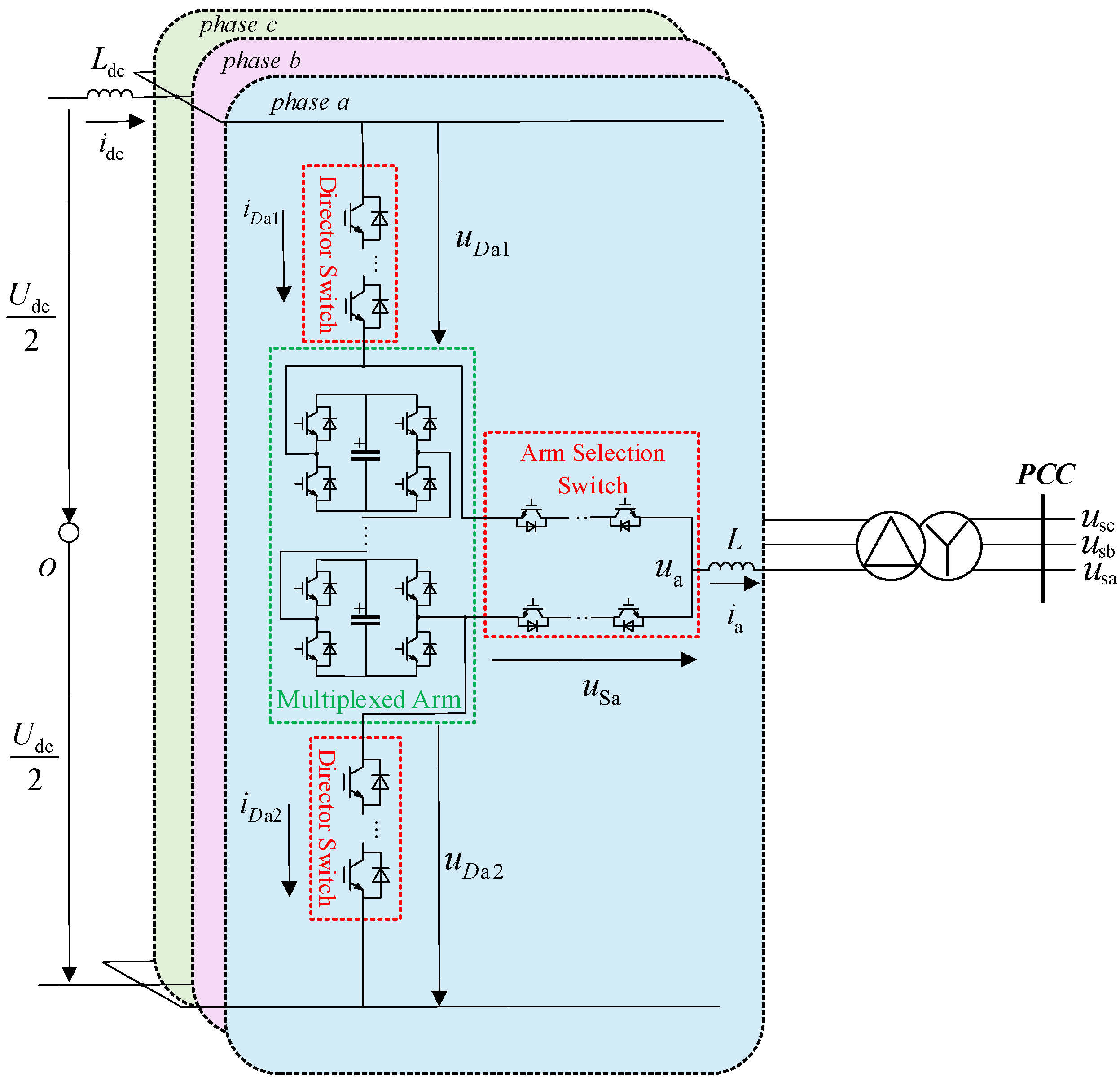
2. Topology and Operation Principle of HAMC

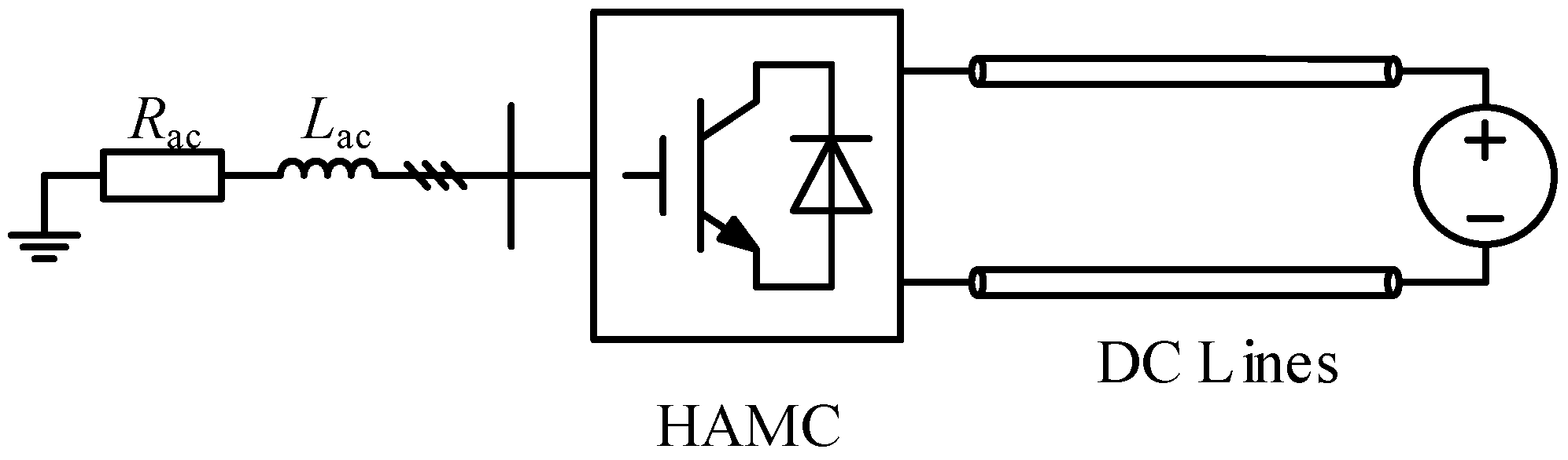
2.1. Topology Description

Hybrid MMCs combine SM chain links with device series switches, bringing together features of MMC and two-level converter topologies. Hybrid MMCs maintain similar AC output characteristics to MMCs but require fewer SMs, making them a promising area of research topic for lightweight MMC designs. As a most compact hybrid MMC topology, HAMCs integrate the ideas of time-division multiplexing and alternate conduction. This innovative topology significantly reduces the weight and volume of MMCs. The HAMC is illustrated in Figure 1, where each phase is divided into four parts: upper arms, lower arms, multiplexed arms, and AC arms. The upper and lower arms consist of director switches (DSs), which are series-connected insulated gate bipolar transistors (IGBTs). The AC arms contain arm selection switches (SSs), also made up of series IGBTs. The two types of switches interact with each other to change the operation mode and alternate the current paths. The multiplexed arms consist of FBCLs to generate sinusoidal half waves. Without changing the modulation strategy, HAMC only operates in an over-modulation state, SM must choose FBSMs.
The number of SMs per phase in a traditional MMC is 2N, while the AAMC nearly halves this requirement for the same rated power transmission. Furthermore, the HAM–MMC reduces the number of SMs by a quarter compared to traditional MMCs. Additionally, HAMC requires 0.5N SMs per phase specifically for shaping circuits in multiplexed arms, significantly contributing to reducing the number of required SMs.

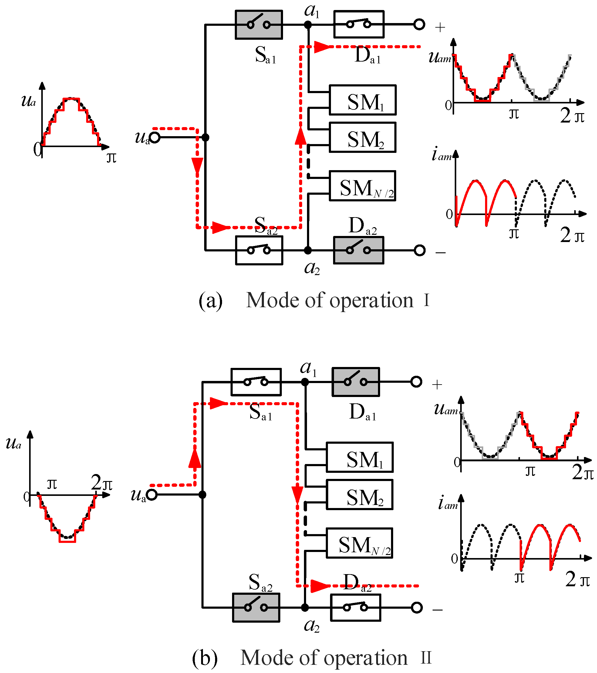
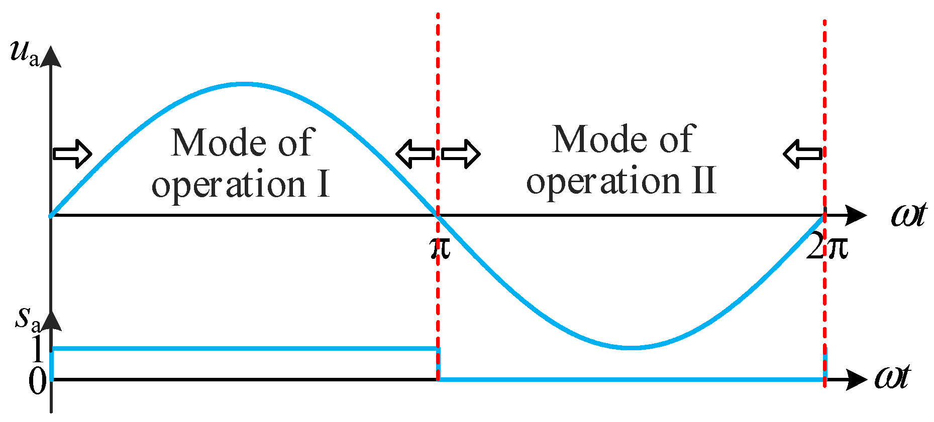
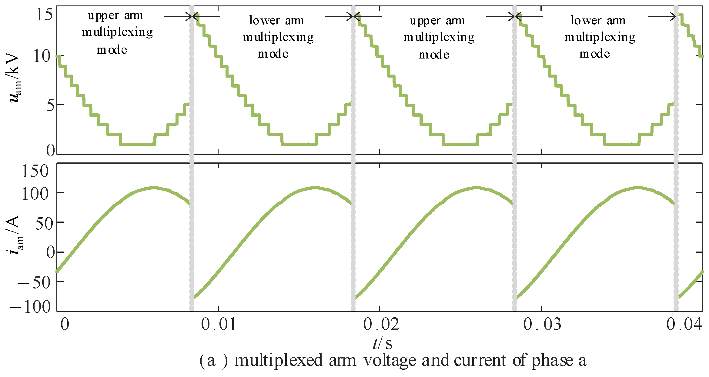
2.2. Operation Principle

Under normal conditions, the DSs of each phase in an AAMC are switched based on the complementary power frequency of the phase voltage reference wave. In HAM–MMCs, the arm selection switches of each phase are switched according to the number of SMs required by the equivalent upper and lower arms. For the HAMC, the DS and arm selection switches need to cooperate to achieve AC and DC voltage conversion, with the operation principle being similar to that of the AAMC. Taking phase a as an example, Figure 2 illustrates the HAMC operation. When the AC output voltage reference is positive, the phase unit operates in the upper arm-multiplexing mode, where Sa2 and Da1 are closed, while Sa1 and Da2 are open. Conversely, when the AC output voltage reference is negative, the phase unit operates in the lower arm-multiplexing mode, with Sa1 and Da2 closed, and Sa2 and Da1 open. This means that the signal of Sa2 matches that of Da1, and the signal of Sa1 matches that of Da2. These two sets of signals alternately complement each other, with the switching frequency being the power frequency.
The switching function Fa of the phase a operation mode is defined as
F a = 1   ,   Upper   arm   multiplexing   mode 0   ,   Lower   arm   multiplexing   mode .
By controlling the switching of the SM, the voltage and current of the multiplexed upper and lower arms can be analyzed. The multiplexed arm voltage uam and iam current can be represented as (2), where ua is the AC voltage, and ia is the output current:
u am = U dc 2 + ( 2 F a + 1 ) u a i am = ( 2 F a 1 ) i a .
Figure 3 shows the operation mode switching principle for each phase of HAMC, where the conduction angle of both the arm selection switch and the director switch within one cycle is π, and the switching frequency corresponds to the power frequency. The shaping circuit of the multiplexed arm alternates between two operation modes. Compared to AAMC, the HAMC can reduce the number of SMs by half through the cooperation of the DC upper and lower arm switches and the AC side switches. Each phase of HAMC operates alternately in two arm-multiplexing conduction modes, enabling full-cycle utilization of the shaping circuit.

3. Energy Balancing Analysis and Control of HAMC

3.1. Energy Balancing Analysis

The exchange of AC and DC power is achieved through the use of submodule capacitors. The submodule capacitor energy balance forms the foundation for the stable operation of hybrid MMC. For HAMC, the submodules are concentrated on the multiplexed arm. Therefore, the energy absorbed and released by the multiplexed arm should be equal in one cycle. This section analyzes the energy balance condition of HAMC. The equations ua and ia of the voltage and current of phase a on the AC side can be expressed as follows:
u a = U m sin ω t i a = I m sin ( ω t φ )
where Um and Im are the fundamental frequency amplitudes of the AC phase voltage and phase current, respectively. ω is the fundamental angular frequency, and φ is the power factor angle.
According to Equations (2) and (3), the expression of uam and iam in a period can be obtained as follows:
u am = U dc 2 ( 1 m sin ω t ) ,   0 < ω t < π U dc 2 ( 1 + m sin ω t ) ,   π < ω t < 2 π i am = I m sin ( ω t φ ) ,   0 < ω t < π I m sin ( ω t φ ) ,   π < ω t < 2 π
where m = 2Um/Udc is the voltage modulation ratio. The multiplexing arm should have no energy accumulation in one cycle.
Δ E am = 1 ω 0 2 π u am i am d ( ω t ) = U dc I m 2 ω ( 4 cos φ π m cos φ ) = 0
From Equation (5), it can be inferred that HAMC needs to operate in overmodulation state. The voltage modulation ratio of 4/π, which is consistent with AAMC. In this situation, HAMC operates at a “sweet spot” so that FBSMs are required to generate the negative arm voltages in the over-modulation mode in order to ensure the stable operation of HAMC and satisfy the system regulation requirements. It is necessary to introduce additional controls to improve the limited operation range of the converter.

3.2. Energy Balancing Control with Harmonic Injected Method

In order to eliminate the limitation of the sweet spot and achieve wide-range voltage regulation of the converter, in this section, the harmonic injection method is applied to HAMC and analyzed. This method relies on driving third-order harmonic currents through a current path created between the middle point of the DC side and the neutral point of a star transformer on the converter side.
Based on Equation (3), after harmonic injection, the modified voltage and current can be expressed as follows:
u a ( t ) = U m sin ( ω t ) U 3 m sin ( 3 ω t θ u ) i a ( t ) = I m sin ( ω t φ ) I 3 m sin ( 3 ω t θ ) .
According to Equations (4) and (6), the expression of uam and iam in a period can be modified as follows:
u am = U dc 2 ( 1 m sin ω t ) + U 3 m sin ( 3 ω t θ u ) = u am 1 ( t ) + u a 3 ( t ) ,   0 < ω t < π U dc 2 ( 1 + m sin ω t ) U 3 m sin ( 3 ω t θ u ) = u am 1 ( t ) u a 3 ( t ) , π < ω t < 2 π i am = I m sin ( ω t φ ) I 3 m sin ( 3 ω t θ ) = i am 1 ( t ) i a 3 ( t ) ,     0 < ω t < π I m sin ( ω t φ ) + I 3 m sin ( 3 ω t θ ) = i am 1 ( t ) + i a 3 ( t ) ,   π < ω t < 2 π   .
Based on Equation (7), the energy accumulated by the modified multiplexed arm in one cycle is
Δ E am = E am 11 E am 13 + E am 31 E am 33 = U m I m 2 m cos φ π 2 cos φ 2 3 m I 3 m I m cos θ .
λ represents the ratio of the third-order harmonic current to the fundamental amplitude:
λ = I 3 m I m .
The third-order harmonic current amplitude ratio λ could be calculated by letting the energy accumulation in (10) equal zero, which is
λ = 3 1 π 4 m cos φ cos θ .
To minimize the size of the third-order harmonic component, let θ = 0:
λ = 3 1 π 4 m cos φ .
The current reference value for a given third-order harmonic injection device can be derived as
i 0 ( t ) = 3 i am ( t ) = 3 λ I m sin ( ω t ) .
This method can ensure the normal operation of the converter when the modulation ratio changes and maintain the overall energy balance of the multiplexed arm. However, there are two significant drawbacks: the need for an additional external current injection device and the potential for excessive harmonic currents to be injected. From Equation (11), it is evident that when the difference between the modulation ratio m and 4/π is large, the ratio of the third-order harmonic current to the fundamental amplitude λ increases. This can lead to the problem of larger harmonic currents being injected.

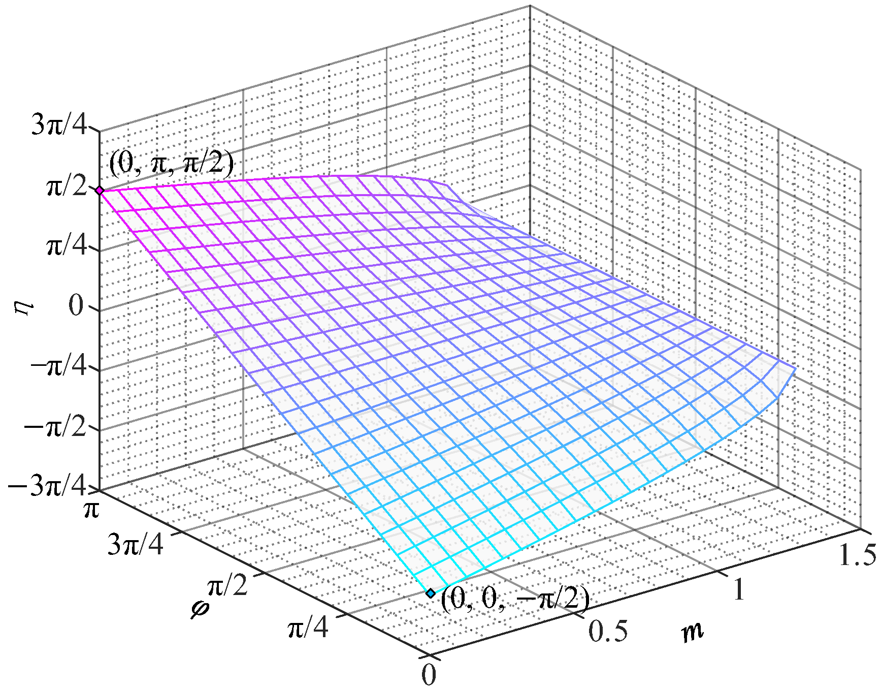
4. The HPSM Strategy of HAMC with Wide Operation

In order to achieve a wide range of voltage regulation, this paper presents a shaping modulation with adjustable commutation angle. Thus, the control freedom is increased to realize the energy balance of the arm. The energy balance of the arm controlled by the commutation angle is analyzed as follows.
The phase unit of the HAMC switches its operation mode at the zero-crossing point of the voltage reference wave. By introducing a commutation angle at switching that lags the AC-side zero-crossing point, the energy balance problem can be eliminated. Taking phase a as an example, as shown in Figure 4, the expression of one period is
F a = 1 η   <   ω t   < π + η 0             π + η   <   ω t   <   2 π + η .
From Fa and (2), it can be concluded that
u am = U dc 2 + ( 1 m sin ω t ) ,         η <   ω t   < π + η U dc 2 + ( 1 + sin ω t ) ,             π + η <   ω t   < 2 π + η i am = I m sin ( ω t φ ) ,                             η <   ω t   < π + η I m sin ( ω t φ ) ,                       π + η <   ω t   < 2 π + η   .
According to Equation (14), the energy accumulated by the multiplexed arm in one cycle is
Δ E am = η 2 π + η u am i am d ( ω t ) = U dc I m ( 4 cos ( η φ ) π m cos φ ) .
In order to balance the capacitor voltage, the energy accumulation should be equal to 0. The relationship between m, φ, and η can be obtained as follows:
η = φ ± arccos ( π 4 m cos φ ) .
When |η| is greater than π/2, the maximum value of the multiplexed arm voltage uam_max is only related to m and can reach a maximum of (1 + 4/π) Udc/2. The larger the uam_max, the greater the number of SMs required for the multiplexed arm. To minimize the increased device cost owing to the use of HPSM, only the commutation angle with the smaller absolute value given by (16) is considered.
η = φ + arccos ( π 4 m cos φ )       π < φ < 0 φ arccos ( π 4 m cos φ )       0 < φ < π
According to (17), η is a function of φ of period π. Taking φ ∈ [0, π] as an example, the change of η with φ and m is shown in Figure 5. When m remains constant, η increases monotonically with φ on [0, π]. When φ ∈ [0, π/2], η increases monotonically with m on [0, 4/π]; when φ ∈ [π/2, π], η decreases monotonically with m on [0, 4/π]. The minimum value of η is −π/2 when m = 0 and φ = 0, and the maximum value is π/2 when m = 0 and φ = π. The overall range of values is [−π/2, π/2].
Based on the above analysis, the expression for the maximum value of the voltage uam_max on the multiplexed arm can be obtained as
u am _ max = U dc 2 ( 1 + m sin η ) .
The changes of uam_max with φ and m can be obtained from Equations (17) and (18), as shown in Figure 6. When m = 0.9, φ = 0 or π, the maximum value of uam_max is 0.82Udc. Therefore, the multiplex arm requires cascading of 0.82N SMs, and the rated voltage of the SM capacitors is Ucn.
With HPSM, the voltage modulation ratio range of HAMC is changed from 4/π to [0, 4/π], thereby expanding the regulating range of the converter. A half-bridge submodule (HBSM) can be used when the voltage modulation ratio is [0, 1]. It can lead to a 23.7% reduction in the number of IGBTs, while further reducing operating losses.

5. Simulation Results of HAMC

In order to verify the effectiveness of the proposed control strategy in HAMC. This paper builds a simulation model of HAMC using Matlab/Simulink in Figure 7. By employing the HPSM strategy, the voltage modulation ratio m is adjusted to 0.9. The specific simulation parameters are shown in Table 1.

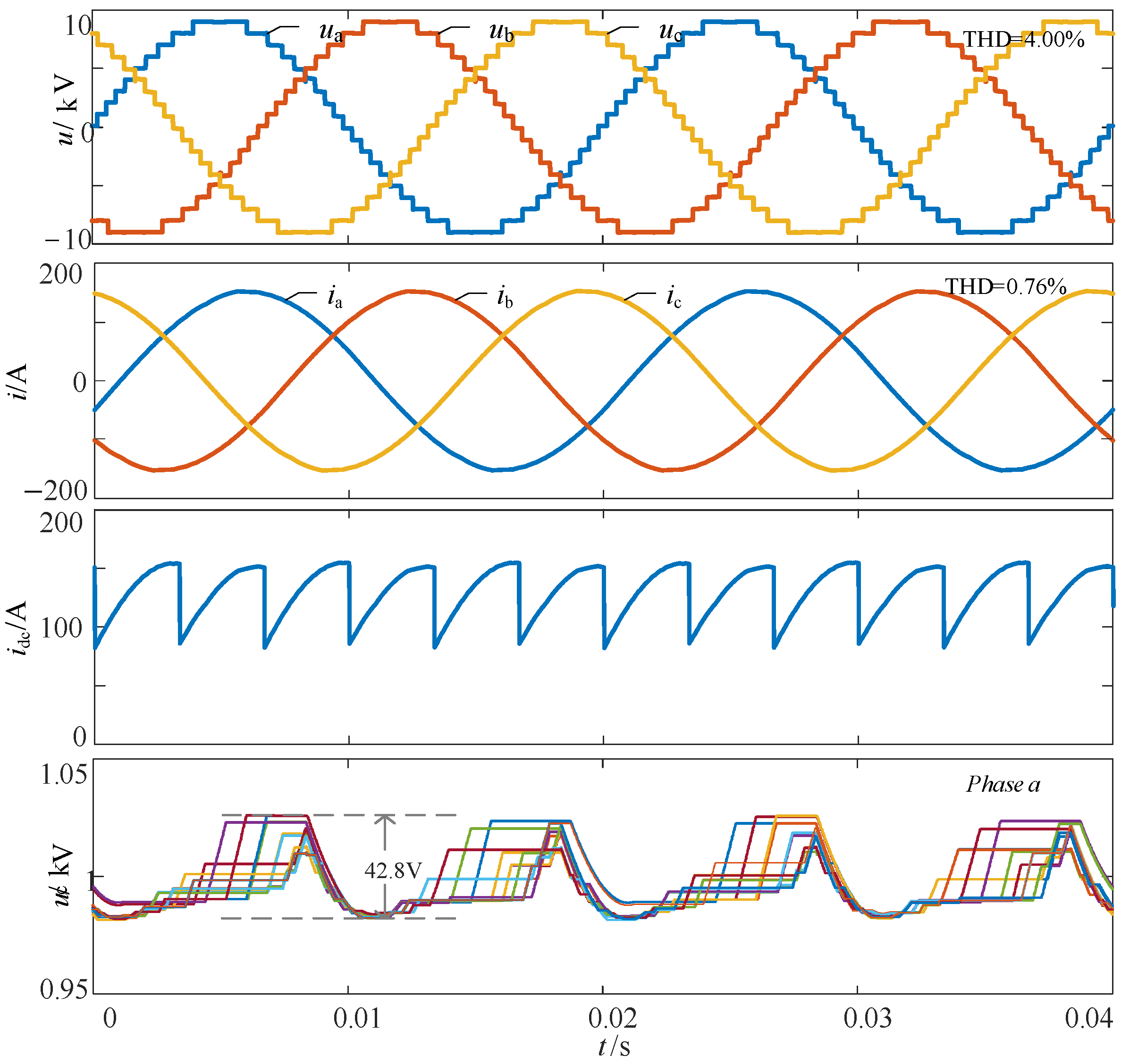
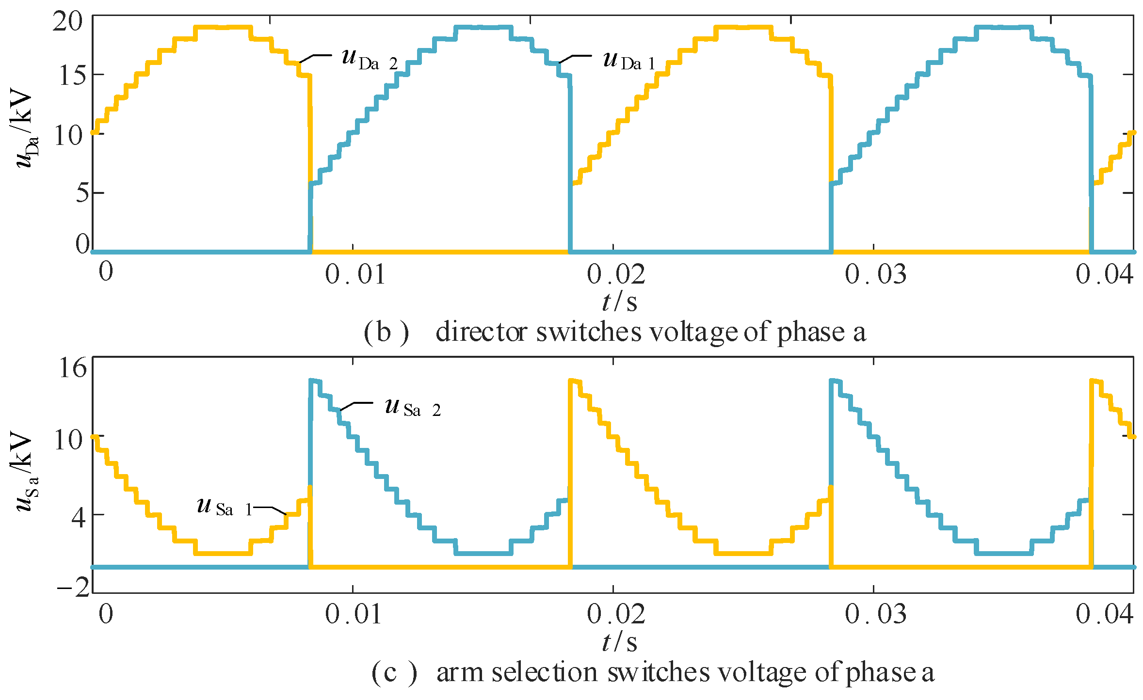
5.1. Steady State Characteristics

As illustrated in Figure 8, the AC output waveforms, DC current, and SM capacitor voltage are generated by HPSM-HAMC in this simulation. Under nearest level modulation (NLM), the HAMC outputs a 19-level phase voltage step wave. The waveforms of phase currents and phase voltages in the AC side exhibit high quality with very low amplitude harmonics. The HAMC has a low submodule capacitor voltage ripple with a capacitor voltage peak-to-peak of 42.8 V. Therefore, with a 59% reduction in sub-module usage, the HAMC with HPSM can have better ac voltage output capability and lower SM capacitance size requirements.
The AC load in the simulation model built in this paper is an inductive load and cosφ = 0.95. The commutation angle η of the HPSM is obtained as −29.6° when m = 0.9. Therefore, the operating mode switching point of the HAMC phase unit will be 29.6° ahead of the phase voltage reference wave over zero. The voltage and current simulation results for the HAMC multiplexed arm are shown in Figure 9, and the simulation results for the director switch voltage and the arm selection switch voltage. From Figure 9a, it can be seen that the upper arm conduction multiplexing mode is triggered “in advance”. The multiplexed arm no longer outputs a negative voltage, and its maximum output voltage is related to the commutation angle η. From Figure 9b,c, Sa1 and Da2 are simultaneously switching, Sa2 and Da1 are simultaneously switching, the switch in the conduction state provides a path for the dc current, and the switch in the turn-off state withstands reversed voltage.

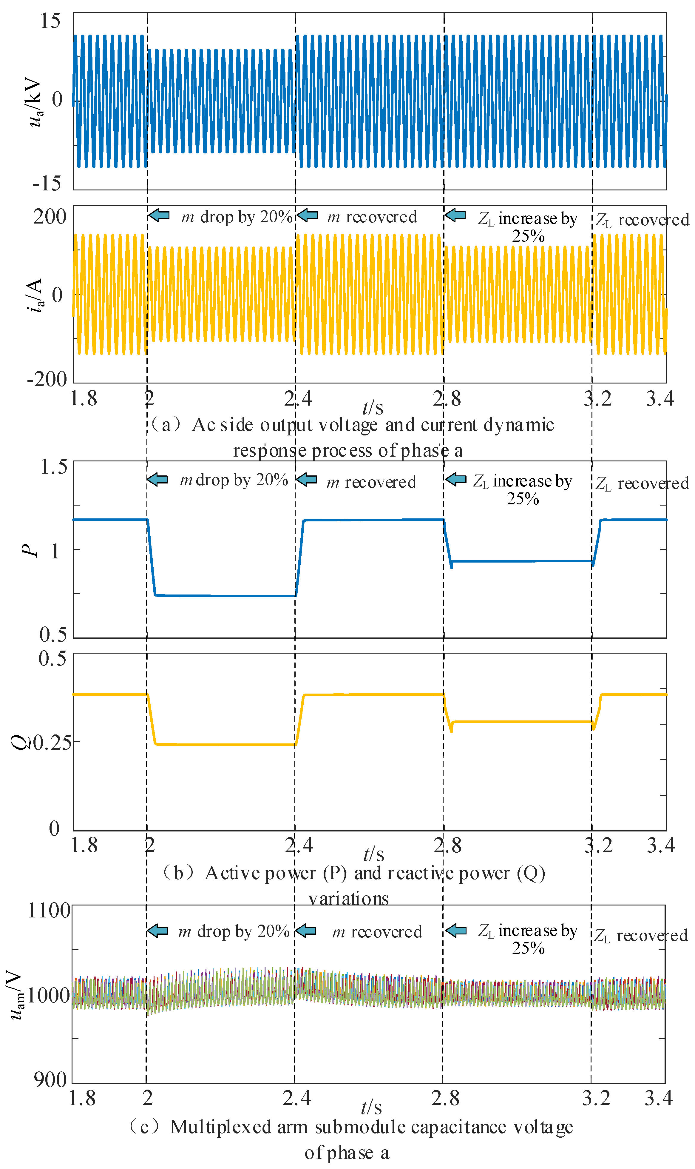
5.2. Dynamic Characteristics

To further verify the feasibility of the strategy proposed in this paper, the dynamic simulation results of HAMC are given in Figure 10. The initial working condition is the same as that of Figure 8, the simulation conditions are set as follows:
(1)
The voltage modulation ratio m is set to drop by 20% at 0.2 s, and the voltage modulation ratio m is recovered at 0.6 s.
(2)
The load resistance is set to increase by 25% at 1.0 s, and the load resistance is restored to its original value at 1.4 s.
From Figure 10a,b, the ac current and output power change steadily when the voltage modulation ratio m and load resistance suddenly change, and there is no significant surge current or power. As shown in Figure 10c, the multiplexed arm sub-module capacitor voltage still has good equalization characteristics when the disturbance occurs and always stays around the rated value of 1 kV. Therefore, the strategy proposed in this paper makes the converter smoothly transition to a new stable operation state with good dynamic characteristics when the working condition changes.

5.3. Performance Comparison with THCI

The operating loss is an important standard to evaluate the economy and efficiency of the converter. For the HVDC converter, the operating loss consists of the conduction loss and switching loss of IGBTs and diodes. The detailed calculation method can be referred to in [27]. Under the above simulation conditions, HPSM is compared with THCI in this section. The resulting operating loss of the converter is shown in Table 2.
For the control strategy proposed in this paper, the switching loss of the DS and arm SS is about 1% of the conduction loss they generate, which is relatively small. In contrast to the third-order harmonic injection method, the increased harmonic current is continuously injected into the arm, greatly increasing the device loss. Then, there is a comparison of the performance of the two control strategies. The comparison is analyzed in terms of modulation range, total harmonic distortion, complexity, and operating loss.
Table 3 provides the output phase voltages of HAMC with THCI and HPSM strategies at a constant power factor (cos φ = 0.95) across different modulation ratios. This further validates the wide-range voltage regulation capability of the two strategies. According to the analysis in (12), λ increases with the modulation range for THCI, requiring the injection of a large amount of additional current. Conversely, HPSM reduces cost by eliminating the need for additional devices while maintaining good voltage output capability.
As seen in Table 4, both control strategies are effective in expanding the operation range of the converter. However, the THCI strategy has a high operating loss and requires additional injection devices. While HPSM is more complex than THCI, its overall performance is significantly better. Based on the above table, the following conclusions can be drawn. HPSM, compared to THCI at the same voltage modulation ratio, exhibits lower THD, indicating better AC harmonic characteristics and higher waveform quality. The lower operating loss implies improved economic, efficiency, and greater practical engineering prospects.

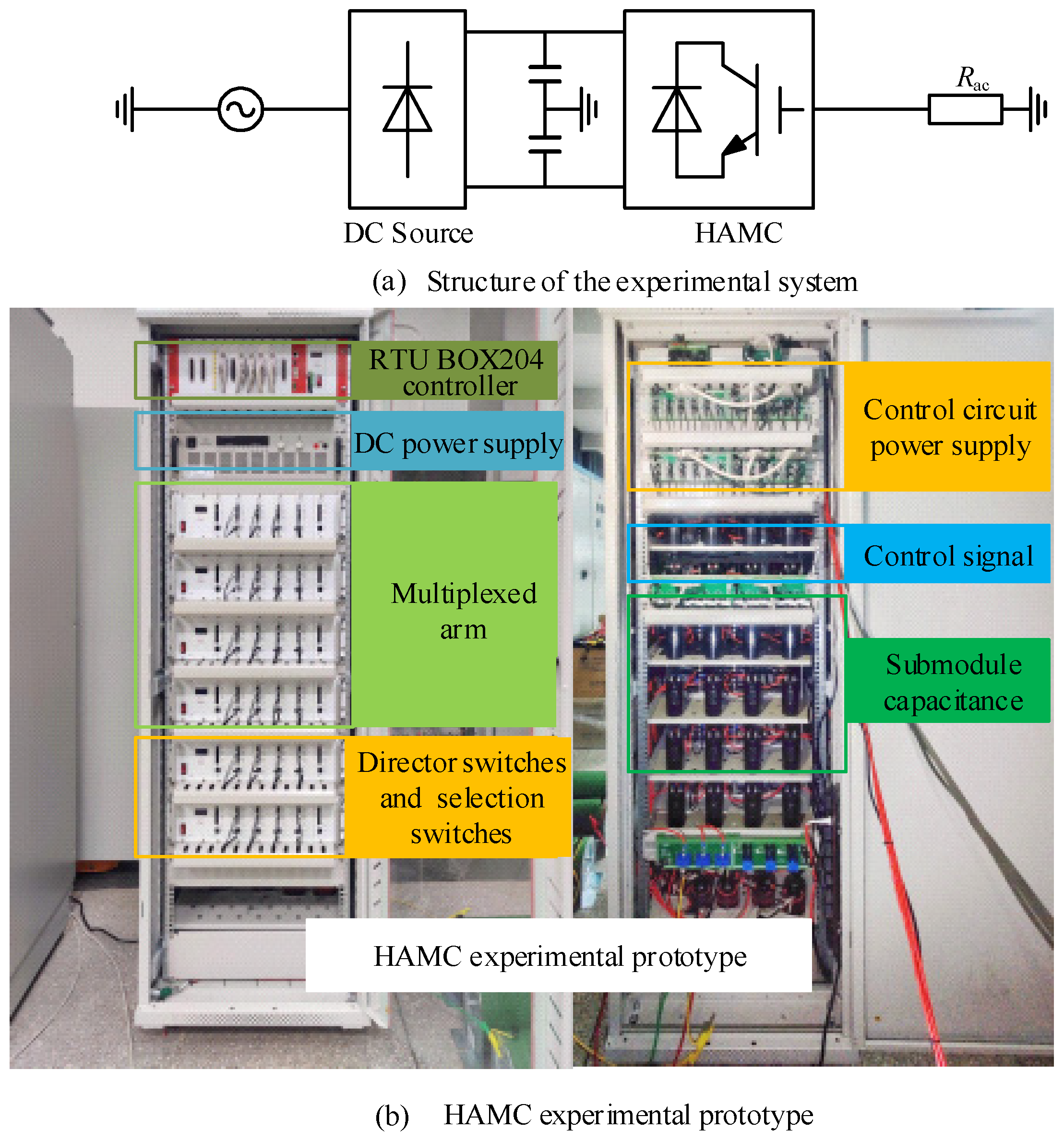
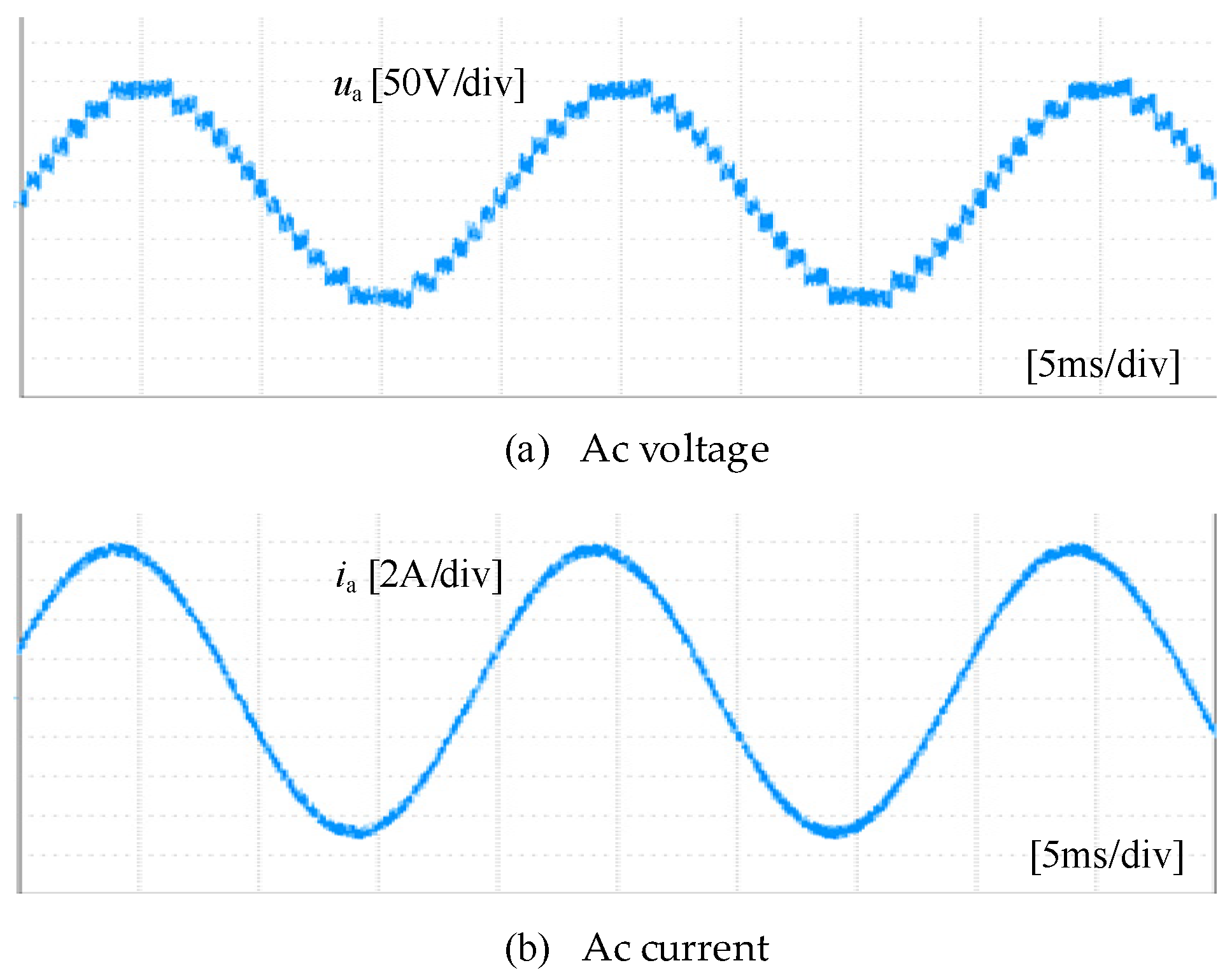
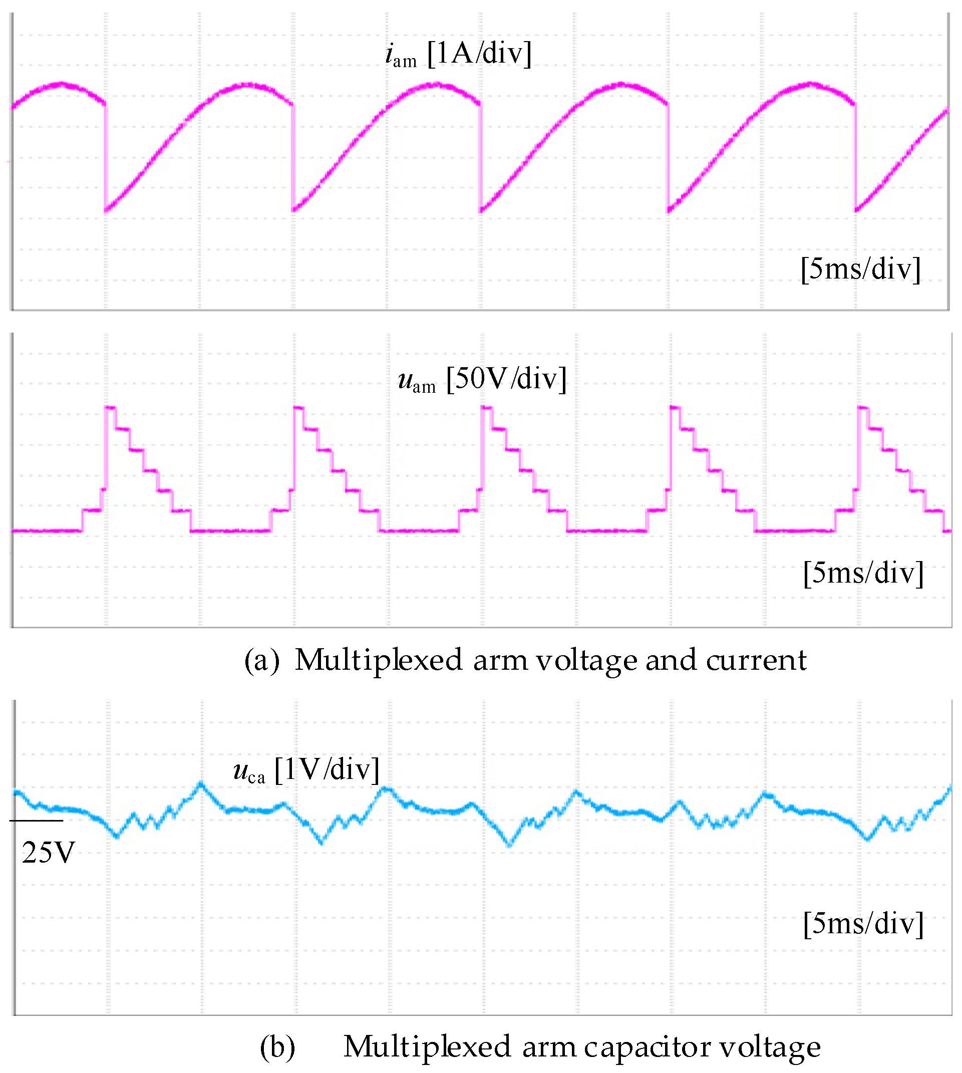
6. Experimental Validations of HAMC

In order to verify the effectiveness of the proposed strategy in HAMC, a scaled-down HAMC is built, as shown in Figure 11. The experimental parameters are listed in Table 5. The prototype control system is implemented using a real-time digital controller (RTU-BOX-204), where the NLM is implemented for the HAMC.
As for the steady-state experiment, the operation results are shown in Figure 12 and Figure 13. It can be seen from Figure 12 that the AC voltage and ac current are in phase a. As shown in Figure 12, the HAMC with six submodules per phase can output 13-level AC voltage, the experimental waveforms of HAMC’s output AC voltage and current have low harmonic distortion rate, indicating good waveform quality. This demonstrates the feasibility of the proposed strategy. The voltage and current of the HAMC multiplexed arm are shown in Figure 13a, and it can be seen that the multiplexed arm no longer outputs a negative voltage, and its maximum output voltage is related to the commutation angle η. The voltage and current of the multiplex arm still fluctuate at double frequency. The submodule capacitance voltage can also remain stable, with small charge and discharge fluctuations within each cycle. This fully demonstrates the effectiveness of the energy balance strategy.

7. Conclusions

Hybrid MMC topologies garnered significant attention as promising MMC alternatives for HVDC applications, though they face energy balancing issues. Based on phase shift control, an energy balancing method for hybrid MMCs is proposed in this paper to expand the operation range. To achieve full-range operation of HAMC, the commutation angle is introduced as a controllable variable. The HPSM strategy controls the commutation angle to match the voltage modulation ratio with the power factor under different operation conditions. The proposed strategy is verified by building simulation models and scale-down experimental prototypes. The following conclusions were drawn:
(1)
Taking the compact HAMC topology as an example, the proposed HPSM strategy can ensure energy balance of the arm with a wide-range modulation ratio and enable the converter with voltage regulation capability.
(2)
With the HPSM strategy, simulated results show that the HAMC can achieve similar power quality, full-range voltage regulation, capacitor voltage, and dynamic response with the conventional MMC.
(3)
Performance comparison illustrated that the HPSM reduces operating loss by 50% compared to the THCI method, while no additional hardware is required.

Author Contributions

J.M. and Y.P. proposed the research topic and designed the model. Z.S. and Y.W. were responsible for guidance, giving constructive suggestions, and revising the paper. Y.G. and Q.N. performed the simulations and analyzed the data. Y.Y. and J.L. improved the manuscript and corrected spelling and grammar mistakes. All authors have read and agreed to the published version of the manuscript.

Funding

This work was supported by the Science and Technology Project of State Grid Zhejiang Electric Power Co., Ltd. (5211DS24000D).

Data Availability Statement

The data presented in this study are available on request from the corresponding author.

Conflicts of Interest

Authors Junchao Ma, Yan Peng, Ying Yang and Jianing Liu were employed by the company State Grid Zhejiang Electrical Power Co., Ltd. Research Institute. Authors Yilei Gu and Qiulong Ni were employed by the company State Grid Zhejiang Electrical Power Co., Ltd. The remaining authors declare that the research was conducted in the absence of any commercial or financial relationships that could be construed as a potential conflict of interest.

Nomenclature

HAMCHalf-wave alternating multilevel converter
SMSubmodule
MVoltage modulation ratio
FaSwitching function
uxmMultiplexed arm voltage (x = a, b, c) (V)
ixmMultiplexed arm current (x = a, b, c) (A)
uxAC phase voltage (x = a, b, c) (V)
ixAC phase current (x = a, b, c) (A)
UdcDC voltage (V)
UmFundamental frequency amplitudes of the AC phase voltage (V)
ImFundamental frequency amplitudes of the AC phase current (A)
EamMultiplexing arm energy accumulation
φPower factor angle
U3mTriple frequency amplitudes of the AC phase voltage (V)
I3mTriple frequency amplitudes of the AC phase current (A)
θThird-order harmonic phase
λRatio of the third-order harmonic current to the fundamental amplitude
i0Third-order harmonic injection current (A)
ηPhase shift angle

References

  1. Dekka, A.; Wu, B.; Fuentes, R.L.; Perez, M.; Zargari, N.R. Evolution of Topologies, Modeling, Control Schemes, and Applications of Modular Multilevel Converters. IEEE J. Emerg. Sel. Top. Power Electron. 2017, 5, 1631–1656. [Google Scholar] [CrossRef]
  2. Nami, A.; Liang, J.; Dijkhuizen, F.; Demetriades, G.D. Modular Multilevel Converters for HVDC Applications: Review on Converter Cells and Functionalities. IEEE Trans. Power Electron. 2015, 30, 18–36. [Google Scholar] [CrossRef]
  3. Debnath, S.; Qin, J.; Bahrani, B.; Saeedifard, M.; Barbosa, P. Operation, Control, and Applications of the Modular Multilevel Converter: A Review. IEEE Trans. Power Electron. 2015, 30, 37–53. [Google Scholar] [CrossRef]
  4. Rao, H.; Zhou, Y.; Zou, C.; Xu, S.; Li, Y.; Yang, L.; Huang, W. Design Aspects of Hybrid HVDC System. CSEE J. Power Energy Syst. 2021, 7, 644–653. [Google Scholar] [CrossRef]
  5. Lin, Z.; Qin, J.; Ma, H.; Liu, J.; Yang, B.; Wang, Y. Design of 500kV Hybrid HVDC Circuit Breaker Control and Protection System. In Proceedings of the 2020 4th International Conference on HVDC (HVDC), Xi’an, China, 6–9 November 2020; pp. 134–139. [Google Scholar]
  6. Yun, H.-J.; Jeong, D.-K.; Kim, H.-S.; Kim, M.; Baek, J.-W.; Kim, J.-Y.; Kim, H.-J. Implementation of a Single-Phase SST for the Interface between a 13.2 kV MVAC Network and a 750 V Bipolar DC Distribution. Electronics 2018, 7, 62. [Google Scholar] [CrossRef]
  7. Cervero, D.; Fotopoulou, M.; Muñoz-Cruzado, J.; Rakopoulos, D.; Stergiopoulos, F.; Nikolopoulos, N.; Voutetakis, S.; Sanz, J.F. Solid State Transformers: A Critical Review of Projects with Relevant Prototypes and Demonstrators. Electronics 2023, 12, 931. [Google Scholar] [CrossRef]
  8. Ma, F.; Kuang, Y.; Wang, Z.; Huang, G.; Kuang, D.; Zhang, C. Multi-Port and -Functional Power Conditioner and Its Control Strategy with Renewable Energy Access for a Railway Traction System. Energies 2021, 14, 6146. [Google Scholar] [CrossRef]
  9. Chen, J.; Hu, H.; Wang, M.; Ge, Y.; Wang, K.; Huang, Y.; Yang, K.; He, Z.; Xu, Z.; Li, Y.R. Power Flow Control-Based Regenerative Braking Energy Utilization in AC Electrified Railways: Review and Future Trends. IEEE Trans. Intell. Transp. Syst. 2024, 25, 6345–6365. [Google Scholar] [CrossRef]
  10. Oliveira, R.; Yazdani, A. An Enhanced Steady-State Model and Capacitor Sizing Method for Modular Multilevel Converters for HVdc Applications. IEEE Trans. Power Electron. 2018, 33, 4756–4771. [Google Scholar] [CrossRef]
  11. Xue, Y.; Xu, Z.; Tu, Q. Modulation and Control for a New Hybrid Cascaded Multilevel Converter With DC Blocking Capability. IEEE Trans. Power Deliv. 2012, 27, 2227–2237. [Google Scholar] [CrossRef]
  12. Merlin, M.M.C.; Green, T.C.; Mitcheson, P.D.; Trainer, D.R.; Critchley, D.R.; Crookes, R.W. A New Hybrid Multi-Level Voltage-Source Converter with DC Fault Blocking Capability. In Proceedings of the 9th IET International Conference on AC and DC Power Transmission (ACDC 2010), London, UK, 19–21 October 2010; pp. 1–5. [Google Scholar]
  13. Merlin, M.M.C.; Green, T.C.; Mitcheson, P.D.; Trainer, D.R.; Critchley, R.; Crookes, W.; Hassan, F. The Alternate Arm Converter: A New Hybrid Multilevel Converter With DC-Fault Blocking Capability. IEEE Trans. Power Deliv. 2014, 29, 310–317. [Google Scholar] [CrossRef]
  14. Wang, Y.; Li, Y.; Wang, C.; Zhang, Z. A Lightweight Hybrid Modular Multilevel Converter Topology for DC Fault Blocking. IEEE J. Emerg. Sel. Top. Power Electron. 2023, 11, 4945–4955. [Google Scholar] [CrossRef]
  15. Hassan, Z.; Watson, A.J.; Tardelli, F.; Clare, J. A Switched Mid-Point Modular Multilevel Converter for HVDC Applications. IEEE Trans. Power Deliv. 2023, 38, 1534–1547. [Google Scholar] [CrossRef]
  16. Wang, Y.; Zhang, Z.; Xu, Y.; Gao, Y.; Xu, L.; Xu, X. Topology and Control of an Arm Multiplexing MMC with Full-Range Voltage Regulation. IEEE Trans. Power Electron. 2024, 1–17. [Google Scholar] [CrossRef]
  17. Yu, Y.; Gao, Y.; Wang, Y.; Li, Y.; Su, Z.; Wang, R. A Half-Wave Alternating Multilevel Converter with High Submodule Utilization. In Proceedings of the IECON 2023—49th Annual Conference of the IEEE Industrial Electronics Society, Singapore, 16–20 October 2023; pp. 1–6. [Google Scholar]
  18. Merlin, M.M.C.; Green, T.C.; Mitcheson, P.D.; Moreno, F.J.; Dyke, K.J.; Trainer, D.R. Cell Capacitor Sizing in Modular Multilevel Converters and Hybrid Topologies. In Proceedings of the 2014 16th European Conference on Power Electronics and Applications, Lappeenranta, Finland, 26–28 August 2014; pp. 1–10. [Google Scholar]
  19. Merlin, M.M.C.; Judge, P.D.; Green, T.C.; Mitcheson, P.D.; Moreno, F.; Dyke, K. Alternate Arm Converter Operation of the Modular Multilevel Converter. In Proceedings of the 2014 IEEE Energy Conversion Congress and Exposition (ECCE), Pittsburgh, PA, USA, 14–18 September 2014; pp. 1924–1930. [Google Scholar]
  20. Farr, E.M.; Feldman, R.; Clare, J.C.; Watson, A.J.; Wheeler, P.W. The Alternate Arm Converter (AAC)—“Short-Overlap” Mode Operation—Analysis and Design Parameter Selection. IEEE Trans. Power Electron. 2018, 33, 5641–5659. [Google Scholar] [CrossRef]
  21. Merlin, M.M.C.; Soto-Sanchez, D.; Judge, P.D.; Chaffey, G.; Clemow, P.; Green, T.C.; Trainer, D.R.; Dyke, K.J. The Extended Overlap Alternate Arm Converter: A Voltage-Source Converter With DC Fault Ride-Through Capability and a Compact Design. IEEE Trans. Power Electron. 2018, 33, 3898–3910. [Google Scholar] [CrossRef]
  22. Moreno, F.J.; Merlin, M.M.C.; Trainer, D.R.; Dyke, K.J.; Green, T.C. Control of an Alternate Arm Converter Connected to a Star Transformer. In Proceedings of the 2014 16th European Conference on Power Electronics and Applications, Lappeenranta, Finland, 26–28 August 2014; pp. 1–10. [Google Scholar]
  23. Mathew, E.C.; Shukla, A. A Novel Submodule Capacitor Voltage Balancing Scheme for Hybrid Cascaded Multilevel Converter by Injection of Zero Sequence Current. In Proceedings of the IECON 2014—40th Annual Conference of the IEEE Industrial Electronics Society, Dallas, TX, USA, 29 October–1 November 2014; pp. 4534–4540. [Google Scholar]
  24. Huang, M.; Li, W.; Zou, J.; Ma, X. Analysis and Design of a Novel Hybrid Modular Multilevel Converter With Time-Sharing Alternative Arm Converter. IEEE Trans. Ind. Electron. 2024, 71, 14–26. [Google Scholar] [CrossRef]
  25. Hou, N.; Li, Y.W. Overview and Comparison of Modulation and Control Strategies for a Nonresonant Single-Phase Dual-Active-Bridge DC–DC Converter. IEEE Trans. Power Electron. 2020, 35, 3148–3172. [Google Scholar] [CrossRef]
  26. Bu, Q.; Wen, H.; Shi, H.; Zhu, Y. A Comparative Review of High-Frequency Transient DC Bias Current Mitigation Strategies in Dual-Active-Bridge DC–DC Converters Under Phase-Shift Modulations. IEEE Trans. Ind. Appl. 2022, 58, 2166–2182. [Google Scholar] [CrossRef]
  27. Zhang, Z.; Xu, Z.; Xue, Y. Valve Losses Evaluation Based on Piecewise Analytical Method for MMC–HVDC Links. IEEE Trans. Power Deliv. 2014, 29, 1354–1362. [Google Scholar] [CrossRef]
Figure 1. HAMC topology.
Electronics 13 03556 g001
Figure 2. HAMC operation mode of phase a.
Electronics 13 03556 g002
Figure 3. HAMC operation mode switching principle.
Electronics 13 03556 g003
Figure 4. Principle of half-wave phase shift modulation.
Electronics 13 03556 g004
Figure 5. Variation in the commutation angle with the power factor angle and the modulation ratio.
Electronics 13 03556 g005
Figure 6. Variation in the maximal multiplexed arm voltage with power factor angle and modulation ratio.
Electronics 13 03556 g006
Figure 7. Structure of the simulated systems.
Electronics 13 03556 g007
Figure 8. Phase and sub-module voltages for HAMC.
Electronics 13 03556 g008
Figure 9. Simulation results of the multiplexed arm and switches of HAMC.
Electronics 13 03556 g009aElectronics 13 03556 g009b
Figure 10. Dynamic simulation results of HAMC.
Electronics 13 03556 g010
Figure 11. Experimental prototype of HAMC.
Electronics 13 03556 g011
Figure 12. Experimental Ac voltage and current waveforms of HAMC.
Electronics 13 03556 g012
Figure 13. Multiplexed arm voltage, current, and capacitor voltage of phase a.
Electronics 13 03556 g013
Table 1. Parameters of Simulation System.
ParametersSymbolValues
Dc-link voltageUdc20 kV
Number of SMs per phaseN10
SM capacitorC3 mF
SM capacitor reference voltageUc1 kV
Load resistanceRload84 Ω
Power factorcosφ0.95
Table 2. HAMC operating loss for two control strategies.
Control StrategyDeviceConduction
Loss/%
Switching Loss/%Operating Loss/%
HPSMSM0.79800.05940.8574
DS0.42320.00370.4269
SS0.21430.00410.2184
Total1.42650.06721.4937
THCISM1.00160.04301.0446
DS0.64960.01320.6628
SS0.57700.01020.5872
Total2.22820.02882.2946
Table 3. Comparison of control variables between HPSM and THCI under different voltage modulation ratios.
mηλPhase Voltage THD/%
THCIHPSM
0.7−40.31.2845.795.20
0.8−35.21.0605.154.59
0.9−29.600.8364.514.00
1.0−23.500.6234.083.65
1.1−16.650.3893.973.23
Table 4. Performance for two control strategies.
SymbolHPSMTHCI
m [0, 4/π] [0, 4/π]
THDLowLow
Control complexityHighLow
Operating lossLowHigh
Table 5. Experimental parameters of the HAMC.
ParametersSymbolValues
Rated active powerPN2.75 kW
Rated frequencyfN50 Hz
Control circleTc0.05 ms
DC bus voltageUdc300 V
Number of SMs per phaseN6
SM capacitorC4.34 mF
SM capacitor reference voltageUc1 kV
AC Load resistanceRload10 Ω
Voltage modulation ratiom0.9
Disclaimer/Publisher’s Note: The statements, opinions and data contained in all publications are solely those of the individual author(s) and contributor(s) and not of MDPI and/or the editor(s). MDPI and/or the editor(s) disclaim responsibility for any injury to people or property resulting from any ideas, methods, instructions or products referred to in the content.

