Article

A Unified Model of a Virtual Synchronous Generator for Transient Stability Analysis

1
China Southern Power Grid Electric Power Research Institute, Guangzhou 510080, China
2
Electric Power Dispatching Control Center of Guangdong Power Grid Co., Ltd., Guangzhou 510080, China
3
Zhaoqing Power Supply Bureau of Guangdong Power Grid Co., Ltd., Zhaoqing 526060, China
4
National Electric Power Conversion and Control Engineering Technology Research Center, Hunan University, Changsha 410082, China
*
Author to whom correspondence should be addressed.
Electronics 2024, 13(17), 3560; https://doi.org/10.3390/electronics13173560 (registering DOI)
Submission received: 29 July 2024 / Revised: 31 August 2024 / Accepted: 3 September 2024 / Published: 7 September 2024

Abstract

:
A virtual synchronous generator (VSG) is prone to transient instability under a grid fault, which leads to the loss of synchronization between the new energy converter and grid, and threatens the operation safety of high-proportion new energy grids. There are a variety of control models in the existing VSG control, including active and reactive power models, which lead to their different transient stabilities. However, the evolution characteristics, correlation between different models of VSG, and the internal mechanism affecting transient stability have not been fully studied. To this effect, this paper analyzes their evolution characteristics based on the existing mainstream VSG control models and establishes a unified VSG model and its equivalent correspondence with other models. Then, the phase plane method is used to comprehensively analyze and compare the transient stability of the VSG unified model with other models. It is pointed out that the key factors affecting the transient stability of different models are three links of primary frequency regulation, reactive power regulation and reactive power tracking. Finally, the correctness of the established VSG unified model and the conclusion of transient stability analysis is verified by experiments.

1. Introduction

To solve the energy crisis and excessive carbon emissions, countries around the world have taken the development of green and sustainable clean energy as their own energy goals [1]. However, the high proportion of new energy represented by photovoltaic and wind power has brought new challenges to the safe and stable operation of power systems. Due to the lack of rotating parts in grid-connected converters and the replacement of many traditional synchronous generators (SGs), the inertia of the system is greatly reduced, which has greatly weakened the anti-interference ability of the system and deteriorated the frequency stability of the system [2]. The ability of virtual synchronous generator (VSG) to provide inertial and damping support for the system by simulating the inertial and damping characteristics of SG is considered one of the most promising technologies [3,4,5]. Although VSG inherits the excellent inertial support characteristics of SG, transient stability problems will also occur when voltage drops, disconnections, trips and other large disturbances occur in the power grid [6,7]. When the voltage drop is serious, VSG may not only cause transient power angle instability but also produce extremely high impulse current [8]. If it is not handled in time, it is easy to lose synchronization with the power grid [9,10], which will lead to the disconnection of new energy sources and even cause cascading failures, which will seriously endanger system safety. Therefore, it is very important to study the transient stability of VSG.
At present, the research on VSG mainly focuses on the analysis and control of small-signal stability [11,12], and the research on transient stability of VSG is relatively less [13,14]. The problem of synchronous stability between the voltage source converter and grid is described in [15,16]. Refs. [17,18] pointed out that reducing the active power command or increasing the reactive power command during a fault can enhance the transient stability of VSG. A method to enhance transient stability by increasing the equivalent output active power of VSG is proposed [19]. In addition to the method to enhance transient stability by adjusting the power of VSG, several methods to enhance transient stability by adjusting the inertia and damping parameters of VSG during faults are also proposed [20,21]. Focusing on the problem of fault overcurrent during a fault, a method to switch VSG control to current-mode control for current limiting during the fault is proposed [22]. A virtual impedance current limiting method for VSG is proposed [23]. It is pointed out that fault current limiting easily causes transient power angle instability of VSG [24], but [22,23] ignores the negative impact of fault current limiting on transient stability. Therefore, [6,25,26] proposes transient stability enhancement methods considering fault current limiting. Although these studies have achieved positive results, most of them are confined to one or several types of VSG control. After more than ten years of research, VSG has developed many control schemes from the original scheme, covering many aspects of changes such as active loop, reactive loop and voltage-current inner loop, which may affect the transient stability of VSG. Due to the different power loop types of different types of VSG, it is impossible to compare the transient stability of different types of VSG [6]. Therefore, it is necessary to establish a unified VSG model and compare different types of VSG based on the unified VSG model.
To solve these problems, many scholars have actively explored them. Ref. [17] points out that different VSG control schemes may present different power angle stability characteristics, but the reasons for different transient power angle stabilities are not studied in this paper. The effects of VSG control parameters, active power and reactive power commands, and reactive power loops (RPLs) on transient stability are studied in [7,13,14,17,25]. The effects of two different types of RPLs on transient stability of VSG are studied [27], but the types of RPLs selected for comparison are too few. The effects of voltage and current inner loop on the transient stability of VSG are studied [28]. Since the bandwidth of the power outer loop is much smaller than that of the voltage and current inner loop, the influence of the voltage and current inner loop on the transient stability can be ignored. The effects of several different types of active power loops (APLs) and RPLs on the transient stability of VSG are studied, and a unified VSG model is established for comparison and analysis [6], but the types of power loops selected for comparison are still too few, and the evolution mechanism between different types of power loops is not analyzed. However, although some achievements have been obtained, there are still many deficiencies in the selection of power loop types and evolution mechanisms, which need to be further studied.
In view of the deficiency of the existing research, in order to better explain the different effects of different types of APLs and RPLs on VSG transient stability based on the action mechanism, avoid the repetition of transient stability research based on a certain type of VSG, and enhance the universality, applicability and correlation among different types of VSG control transient stability research theories, a unified VSG model is established and the transient stability influence mechanisms of different types of VSGs are studied in this paper. The main contributions of this paper are summarized as follows:
(1)
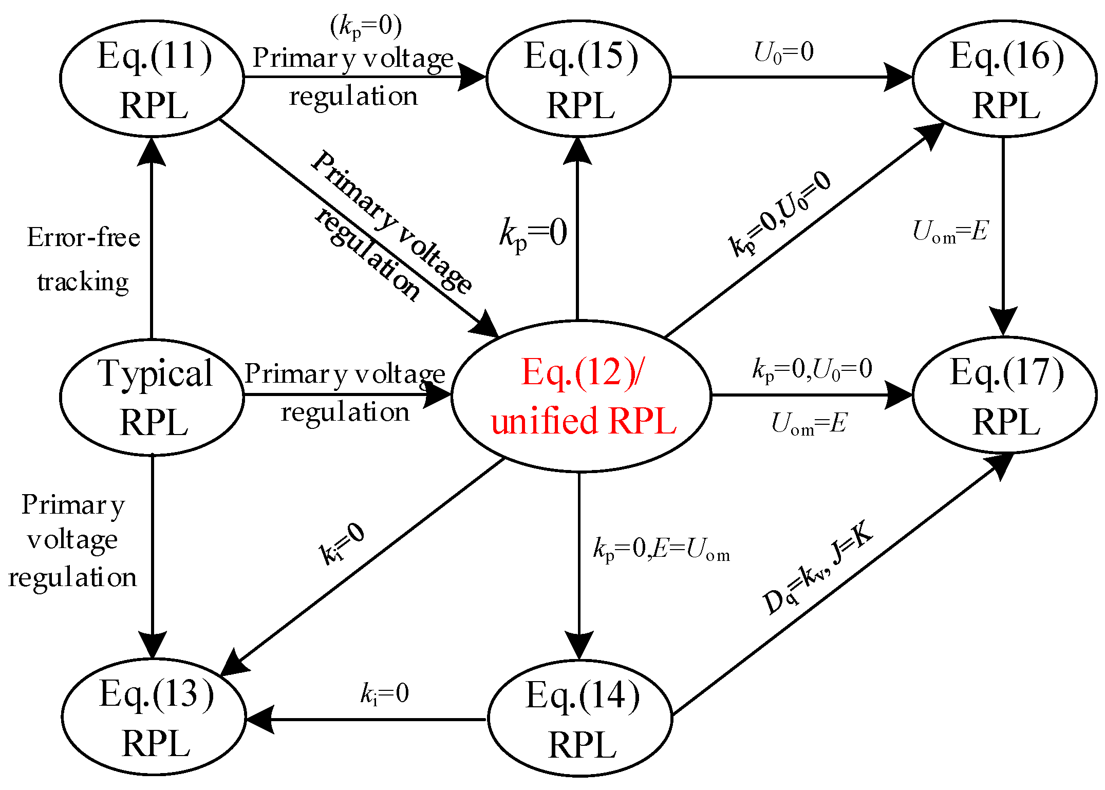
By comparing and analyzing the evolution characteristics of APL types and RPL types, a representative unified VSG model is established, and the parametric equivalent correspondences between the APL of unified VSG and other types of APLs and between the RPL of unified VSG and other types of RPLs are established.
(2)
A large-signal model of unified VSG is established, and based on this model, the influence of unified VSG control parameters on transient stability is analyzed.
(3)
Based on the analysis of the influence of different action links on the transient stability of VSG, the transient stability between VSG control with different types of APLs and the transient stability between VSG control with different types of RPLs are compared. It is pointed out that under the same control parameters, the primary frequency regulation in APLs, the reactive power voltage regulation and the reactive power error-free tracking in RPLs are the essential reasons for the different transient stabilities of different types of VSG.
The rest of this paper is organized as follows. In Section 2, the typical model of VSG control is introduced. In Section 3, different VSG control models are introduced, and the evolution characteristics of each model are analyzed. In Section 4, the large-signal model of unified VSG control is established, and the influence of model parameters on transient stability is analyzed by phase portrait. In Section 5, different VSG control models are compared and analyzed based on three aspects: different action links and different types of APLs and RPLs. In Section 6, the unified VSG control mode and transient stability theoretical analysis are verified. In Section 7, some important conclusions are drawn.

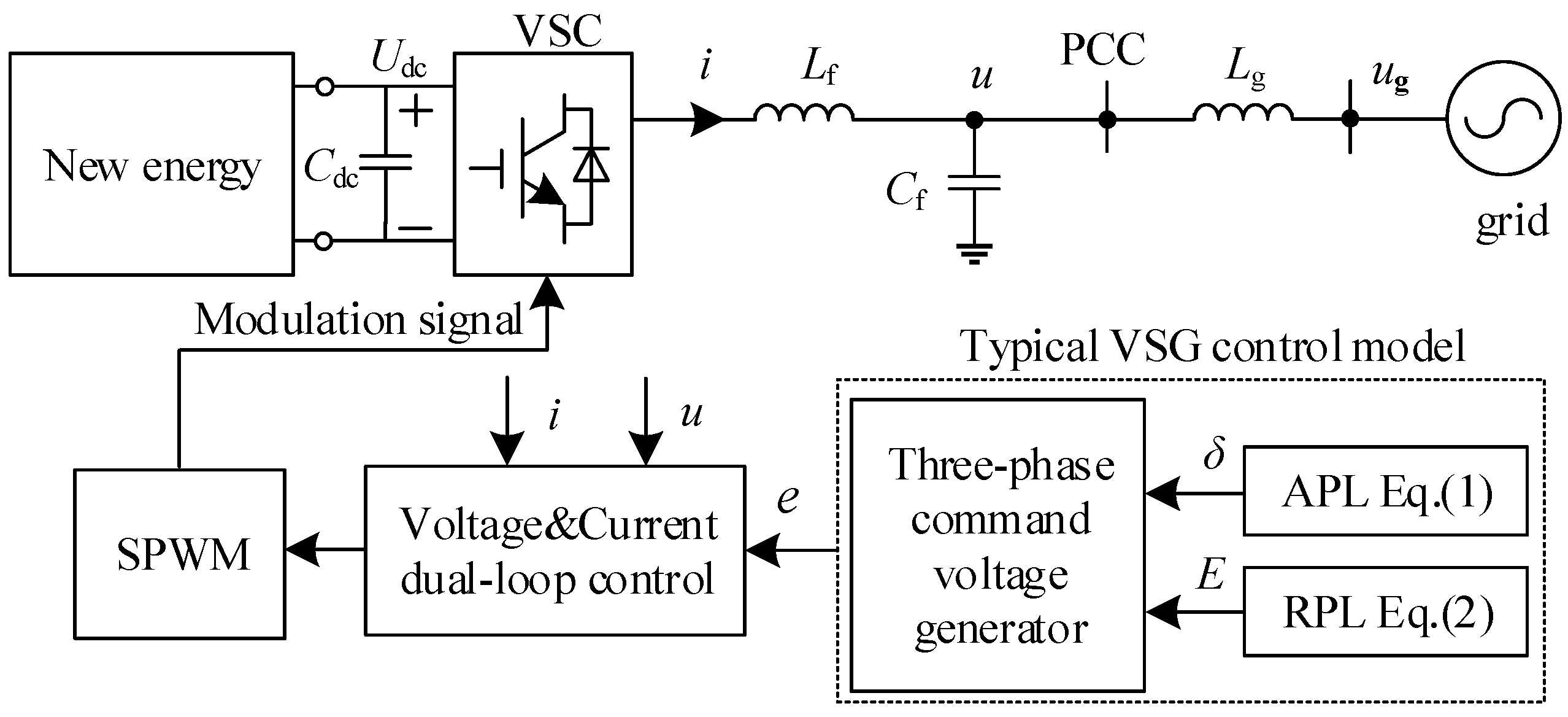
2. Typical Model of Virtual Synchronous Generator Control

Figure 1 shows the main circuit and VSG control structure of the new energy grid-connected system. The power generation system composed of new energy sources, such as photovoltaic and wind power and energy storage units, is connected to the VSG control converter (VSC) through the front-end converter and the DC-side capacitor Cdc. The VSG port is connected to the common connection point (PCC) through the LC filter with the inductance and capacitance of Lf and Cf, and then connected to the public power grid through the transmission line with impedance of Zg. u and ug are PCC terminal voltage and grid voltage, i is VSG output current, and Udc is the DC side voltage. It is worth pointing out that the new energy sources connection in Figure 1 on the DC side is only to indicate that the main circuit and control are applicable to the new energy, and in fact, the new energy also needs to be configured with the front-end circuit and energy storage unit.
Furthermore, the VSG control model includes two parts: active power loop and reactive power loop. The APL is in the form of torque, and the RPL is in the form of droop control. This kind of model is called the typical model of VSG control, and its equation is as follows:
T m T e D Δ ω = J d Δ ω d t Δ ω = ω ω 0
E = U 0 + k q Q m Q e
where J and D are the inertia and the damping coefficient. ω, ω0 and Δω are power angle, angular frequency, rated angular frequency, and angular frequency deviation, respectively. Tm and Te are torque command value and actual value. Qm and Qe are reactive power command value and actual value. E and U0 are VSG output voltage command value and rated value. kq is reactive voltage regulation coefficient.
Assuming that the VSG output voltage is Eδ, the grid voltage phasor is Ug∠0, and the VSG output voltage phasor is U0δ0 during steady-state operation. It is usually considered that the impedance Zg between the VSC and the grid is inductive, namely, Zg = Xg = ωLg, by ignoring the line resistance. The active and reactive power transmission power Pe and Qe between the VSG and the grid are
P e = 3 E U g 2 X g sin δ Q e = 3 E 2 3 E U g cos δ 2 X g
According to the calculation formula T = P/ω0 between torque and active power, combined with Equation (3), Te can be calculated to realize VSG control.

3. Models and Characteristics Analysis of Different VSG Controls

3.1. Type and Evolution Characteristics Analysis of APL

In addition to the typical VSG control model, this section comprehensively introduces the existing four mainstream VSG control APLs.
(1)
A VSG control in which the dΔω/dt of the APL is replaced by dω/dt is proposed in [29], which is expressed as
T m T e D ω ω 0 = J d ω d t
(2)
A VSG control APL in the form of power loop is proposed in [30], which is expressed as
P m P e D ω ω 0 = J d ω d t
(3)
A VSG control APL with primary frequency regulation is proposed in [31], which is expressed as
P ref P e D ω ω 0 = J d Δ ω d t P ref = P m k f ω ω 0
(4)
The APL in the power form of the typical VSG control model is proposed in [32], and its expression is
P m P e D ω 0 Δ ω = J ω 0 d Δ ω d t
In Equations (4)–(7), Tm, Pm and Pe are the active torque command value, the active power command value and the actual active power value, respectively. Pref is the active power given value of the primary frequency regulation link, and kf is the frequency regulation coefficient.
By comparing Equations (4)–(7) with Equation (1), it can be found that the evolution characteristics of the APL of these VSG models are mainly manifested in three aspects: (1) whether to adopt the torque form or the power form; (2) the derivative term is in the form of angular frequency ω or angular frequency deviation Δω; (3) whether to introduce primary frequency regulation. To comprehensively analyze the relationship between different types of APLs, a detailed analysis is carried out below.
Firstly, according to the calculation formula T = P/ω0 between torque and active power, the APL of Equation (1) can be converted to Equation (7). If the inertia and damping of the two equations are equal, the two equations are completely equivalent. In addition, the comparison between Equation (7) and Equation (5) shows that the two equations are the same in form. If 0 = D, J = J, the two equations are the same. If J and D are equal in the two equations, then 0 > D, 0 > J; that is, an APL in the torque form has greater inertia and damping than an APL in the power form.
Secondly, since Δω = ωω0, dΔω/t = dω/dt, so the APL derivative term of Equation (1) is the same as that of Equation (4). Similarly, the derivative terms in Equations (1), (6) and (7) can be interchanged with Equations (4) and (5). It is worth noting that since the grid frequency has very small fluctuations, the grid frequency ωg is considered constant; i.e., ωg = ω0, so ∆ω = ω − ωg can also be replaced by ωω0.
Thirdly, the primary frequency regulation link of Equation (6) enables VSC to actively participate in grid frequency regulation when the grid frequency is disturbed. By further combining and deforming Equation (6), it can be obtained that
P m P e D + k f Δ ω = J d Δ ω d t
Of course, the primary frequency regulation link can also be substituted into the APLs of other VSG models to obtain another VSG control model. For example, by substituting it into Equation (4), another VSG control APL can be obtained:
T ref T e D + k f ω 0 Δ ω = J d Δ ω d t
By comparing the Equations (5) and (8) with an APL in the power form and the Equations (1), (4) and (9) with an APL in the torque form, it is found that they are equivalent in form; that is, the introduction of primary frequency regulation link is equivalent to increasing D.
Based on the above analysis, the four types of APLs in Equations (4)–(7) are unified to establish a unified APL model that can be freely converted between each other. The model is as follows:
T m T e D eq ω ω 0 = J eq d Δ ω d t
Further, by comparing the unified APL model with other types of APL models, the equivalent correspondence of different APL model parameters is established as shown in Table 1.
According to the corresponding relationship of the parameters shown in Table 1, the VSG unified APL model is completely equivalent to other types of APL models, and can be converted to each other, as follows:
( 1 ) ( 4 ) ( 5 ) ( 6 ) ( 9 ) ( 10 ) : T m T e D eq ω ω 0 = J eq d Δ ω d t
Obviously, J and D in Equations (4)–(9) are different, and their magnitude relations are Jeq < Jeqω0, Deq-kf/ω0 < Deqω0-kf < Deqω0. If J and D are kept unchanged, different types of APLs will affect the transient stability of VSG.

3.2. Type and Evolution Characteristics Analysis of RPL

Like the case of APLs, in addition to the typical VSG control model, there are also other types, which have also been widely used to a certain extent. This section comprehensively introduces seven representative RPL types.
(1)
An RPL with a reactive power tracking link in VSG control is proposed in [33]. The RPL is designed to eliminate the reactive power tracking error, which is expressed as
E = U 0 + k p + k i s Q m Q e
(2)
On the basis of Equation (11), an RPL with a reactive voltage regulation link in VSG control is proposed in [6]. The RPL enables VSC to actively participate in grid voltage regulation when grid voltage disturbance occurs, which is expressed as
E = U 0 + k p + k i s Q ref Q e Q ref = Q m D q U om U 0
(3)
An RPL consisting of reactive power regulation and voltage regulation in VSG control is proposed in [34]. The RPL not only enables VSC to have reactive power regulation capability but also enables VSC to actively participate in grid voltage regulation capability when grid voltage disturbance occurs, which is expressed as
E = U 0 + k q Q m Q e + k v U 0 U om
(4)
An RPL like an APL in VSG control is proposed in [35]. The RPL makes the relationship between the reactive power and the output voltage of VSG like the relationship between inertia and damping of APL, which is expressed as
J q d ( E U 0 ) d t = Q m Q e D q E U 0
(5)
Similar to Equation (13), an RPL with the difference between the actual value Uom and U0 of the PCC point voltage as the damping term in VSG control is proposed in [36], which is expressed as
J q d ( E U 0 ) d t = Q m Q e D q U om U 0
(6)
Analogous to the excitation regulation characteristics of SG, an integral form of an RPL with the sum of reactive power and voltage regulation in VSG control is proposed in [37], which is expressed as follows:
E = Q m Q e + k v U 0 U om K s
(6)
An RPL with reactive voltage regulation characteristics like Equation (16) is proposed in [27], which is expressed as
E = Q m Q e + k v U 0 K s + k v
In Equations (11)–(17), kp and ki are the proportional and integral coefficients, respectively. Dq and kv are the same as kq in Equation (2), which are the coefficients of reactive power voltage regulation. Qref is the given value of the primary reactive power voltage regulation link, Jq is the inertia coefficient of the RPL, and K is the integral regulation coefficient.
By comparing Equations (11)–(17) with Equation (2), it can be found that the evolution characteristics of the RPLs of these VSG models are mainly manifested in two aspects: (1) whether to introduce the reactive power error-free tracking link; (2) whether to introduce a reactive voltage regulation link. To comprehensively analyze the relationship between different types of RPLs, a detailed analysis is carried out below.
Firstly, compared with Equation (2), Equation (11) introduces the reactive power error-free tracking link. When ki = 0, the two equations are the same. Therefore, the classical reactive power loop model of Equation (2) can be regarded as a special case of the Equation (11) reactive power loop. In the physical sense, the former has a reactive power tracking error, while the latter can achieve reactive power error-free tracking.
Secondly, Equation (12) introduces a reactive voltage regulation link based on Equation (11) and further deforms it to obtain
E = U 0 + k p + k i s Q m Q e + D q U 0 U om
It can be seen from formula (18) that if ki = 0, Dq = 0, then Equations (12) and (2) are the same. Therefore, Equation (2) can also be regarded as a special case of Equation (12). In the physical sense, the former has a reactive power tracking error, while the latter can not only realize reactive power tracking without error but also actively participate in grid voltage regulation.
Imitating the evolution of Equation (12), if the primary reactive voltage regulation is introduced into Equation (2), then
E = U 0 + k q Q m Q e + k q D q U 0 U om
A comparison between Equation (19) and (13) shows that the forms of the two equations are the same. If kv = kqDq, then both are identical. Furthermore, if kp = 0 in (11), only the integral link is retained, and a reactive power voltage regulation link is introduced on this basis of
E = U 0 + k i s Q m Q e + D q U 0 U om
It is not difficult to find that Equation (20) is a special form of kp = 0 in Equation (18). The following two equivalent forms can be obtained by further deformation:
1 k i d E U 0 d t = Q m Q e + D q U 0 U om
E = U 0 + Q m Q e + D q U 0 U om 1 k i s
The comparison among Equation (21) and Equations (14) and (15) shows that the forms of the three equations are consistent. If Jq = 1/ki, Equations (21) and (15) are the same. The difference between Equations (14) and (15) is only in whether the voltage loop adopts E or Uom. Because E = Uom in steady state, replacing the two does not affect the control performance of VSG. If E is replaced by Uom in Equation (21), Equation (21) is the same as Equation (14). In addition, by comparing Equation (22) and Equations (16) and (17), it can be found that if K = 1/ki, kv = Dq, and U0 is ignored, then Equations (22) and (16) are identical; if K = 1/ki, kv = Dq, replacing Uom with E and ignoring U0, then Equations (22) and (17) are identical. Since whether to ignore U0 only affects the dynamics of voltage tracking in the initial stage and does not affect the transient and steady-state performance of VSG, Equations (13)–(17) can also be regarded as a special case of Equation (12). The evolution of the above types of RPLs is shown in Figure 2.
According to the evolution relationship of Figure 2, the unified RPL model of Equation (12) can be established, which can be converted to other models. At the same time, by comparing the unified RPL model with other types of RPL models, the equivalent correspondence of different types of RPL parameters shown in Table 2 can be established. When the equivalent relationship is satisfied, the unified RPL model is completely equivalent to other RPL models. The specific performance is as follows.
Obviously, the parameters in the seven types of RPL models are also different due to the introduction of primary reactive power regulation and reactive power error-free tracking. Even if the parameters of the seven types of RPL models of VSG are equal, the seven models are not completely equivalent. The introduction of RPL types will affect the transient stability of VSG due to the introduction of different links.

4. Large-Signal Model and Transient Stability Analysis of VSG Unified Model

4.1. Large-Signal Model of VSG Unified Model

To study the influence of the VSG unified model on transient stability, it is very important to establish a VSG unified model based on the aforementioned unified APL and RPL model. Rewriting the complete VSG unified model,
T m T e D eq ω ω 0 = J eq d Δ ω d t E = U 0 + k p + k i s Q m Q e + D q U 0 E
Substituting Qe in Equation (3) into the RPL of Equation (23) and deriving E, we can obtain
d E d t = k i Q m 1.5 E 2 1.5 E U g cos δ X g + D q U 0 E 1.5 k p U g E sin δ X g d δ d t k p D q + 1 + 3 k p E X g 1.5 k p U g cos δ X g
In particular, when kp = 0 and ki ≠ 0, then Equation (24) becomes
d E d t = k i Q m 1.5 E 2 1.5 E U g cos δ X g + D q U 0 E
when kp ≠ 0 and ki = 0. Then, Equation (24) becomes
d E d t = 1.5 k p U g E sin δ d δ d t k p D q + 1 X g + 3 k p E 1.5 k p U g cos δ
The VSG unified APL model shown in Equation (10) can be written as a differential equation about δ:
J eq d 2 δ d t 2 = T m T e D eq d δ d t
Substituting Pe in Equation (3) into Equation (26), the second-order nonlinear differential equation about δ can be obtained as follows:
d 2 δ d t 2 = 1 J eq ω 0 P m 3 E U g 2 X g sin δ D eq J eq d δ d t
Let the state vector x = x 1 , x 2 , x 3 T = δ , Δ ω , E T , and combining the Equations (25) and (27), the large-signal model of the unified VSG model can be obtained as follows:
x 1 · x 2 · x 3 · = x 2 1 J eq ω 0 P m 3 U g x 3 2 X g sin x 1 D eq J eq x 2 k i X g Q m k i 1.5 x 3 2 1.5 U g x 3 cos x 1 + k i X g D q U 0 x 3 1.5 k p U g x 2 x 3 sin x 1 k p D q + 1 X g + 3 k p x 3 1.5 k p U g cos x 1

4.2. Transient Stability Analysis of VSG Unified Model

In this section, based on the established large-signal model, the phase portrait method is used to analyze the transient stability of the VSG unified model under two types of faults: I (k = 0.5) and II (k = 0.2), where the fault depth k = UgF/UgN. UgF and UgN are fault grid voltage and rated voltage, respectively. For the convenience of presentation, the control parameters in subsequent figures are all without units. Except kp and ki, which are dimensionless, the units of other parameters are shown in Chapter 6.

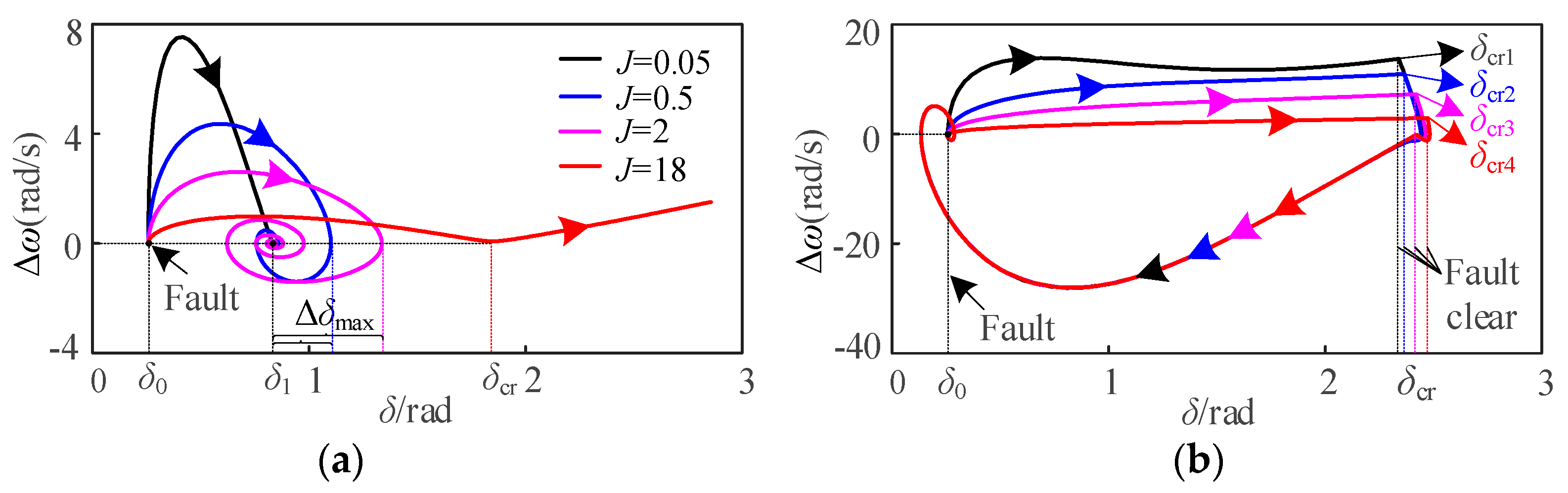
4.2.1. Influence of J Variation on Transient Stability of Unified VSG

To analyze the influence of J variation on the transient stability of unified VSG, taking D = 3, kp = 0.01, ki = 0.5 and Dq = 160 as an example, according to the large-signal model of Equation (29), the phase portraits of the unified VSG model with four different values of J equal to 0.05, 0.5, 2 and 18 under I and II faults are drawn as shown in Figure 3. δ0 and δ1 denote the steady-state power angles before and after the fault, respectively. δcr and ∆δmax denote the critical clearing angle and power angle overshoot, respectively.
It can be seen from Figure 3a that when J is equal to 0.05, 0.5 and 2, respectively, VSG is transiently stable during the fault, but the power angle overshoot ∆δmax is gradually increasing. When J = 18, VSG is transiently unstable during the fault. It can be seen from Figure 3b that under the four values of J = 0.05, 0.5, 2 and 18, the corresponding critical clearance angle δcr gradually increases; that is, δcr1 < δcr2 < δcr3 < δcr4, and the corresponding critical clearance time is also longer. Therefore, under fault I, the larger the J is, the larger the power angle overshoot ∆δmax is, and the more unfavorable it is for VSG to maintain transient stability. However, under fault II, the larger the J is, the more beneficial it is to enhance the transient stability of VSG. The results show that the influence of J on the transient stability of VSG is related to the fault type. Under fault I, the smaller J is more conducive to enhancing the transient stability. Under fault II, the larger J is more conducive to enhancing the transient stability.

4.2.2. Influence of D Variation on Transient Stability of Unified VSG

To analyze the influence of D variation on the transient stability of unified VSG, taking J = 0.05, kp = 0.01, ki = 0.5 and Dq = 160 as an example, according to the large-signal model of Equation (29), the phase portraits of the unified VSG model with four different values of D equal to 3, 40, 80 and 160 under faults I and II are drawn as shown in Figure 4.
It can be seen from Figure 4a that the VSGs with four different D values are transiently stable during the fault, but with the increase of D, the corresponding steady-state power angle δ1 gradually decreases. In addition, it can be seen from Figure 4b that under the four values of D = 3, 40, 80 and 160, the corresponding critical clearance angle δcr gradually increases; that is, δcr1 < δcr2 < δcr3 < δcr4, and the critical clearance time corresponding to δcr is also longer, but when D = 40, 80 and 160, the corresponding δcr changes a little. Therefore, under the two types of faults I and II, the larger the D is, the more favorable it is to enhance the transient stability of VSG, and the influence of D on the transient stability of VSG is independent of the fault type. At the same time, the results also show that when D increases to a certain extent, its influence on transient stability will be significantly weakened.

4.2.3. Influence of kp Variation on Transient Stability of Unified VSG

To analyze the influence of kp variation on the transient stability of unified VSG, taking J = 0.05, D = 3, ki = 0.5 and Dq = 160 as an example, the phase portraits of the unified VSG model with four different values of kp equal to 1 × 10⁻³, 0.01, 0.1 and 5 under faults I and II are drawn as shown in Figure 5.
It can be seen from Figure 5a that the VSGs with four different kp values are transiently stable during the fault, but with the increase of kp, the corresponding steady-state power angle δ1 decreases. Moreover, it can be seen from Figure 5b that under the four values of kp = 1 × 10⁻³, 0.01, 0.1 and 5, the corresponding critical clearance angle δcr gradually increases; that is, δcr1 < δcr2 < δcr3 < δcr4, and the critical clearance time corresponding to δcr is also longer, but when kp = 1 × 10⁻³ and 0.01, the corresponding δcr changes a little. Therefore, under the two types of faults I and II, the larger the kp is, the more favorable it is to enhance the transient stability of VSG, and the influence of kp on the transient stability of VSG is also independent of the fault type. At the same time, the results also show that when kp decreases to a certain extent, its influence on transient stability will be significantly weakened.

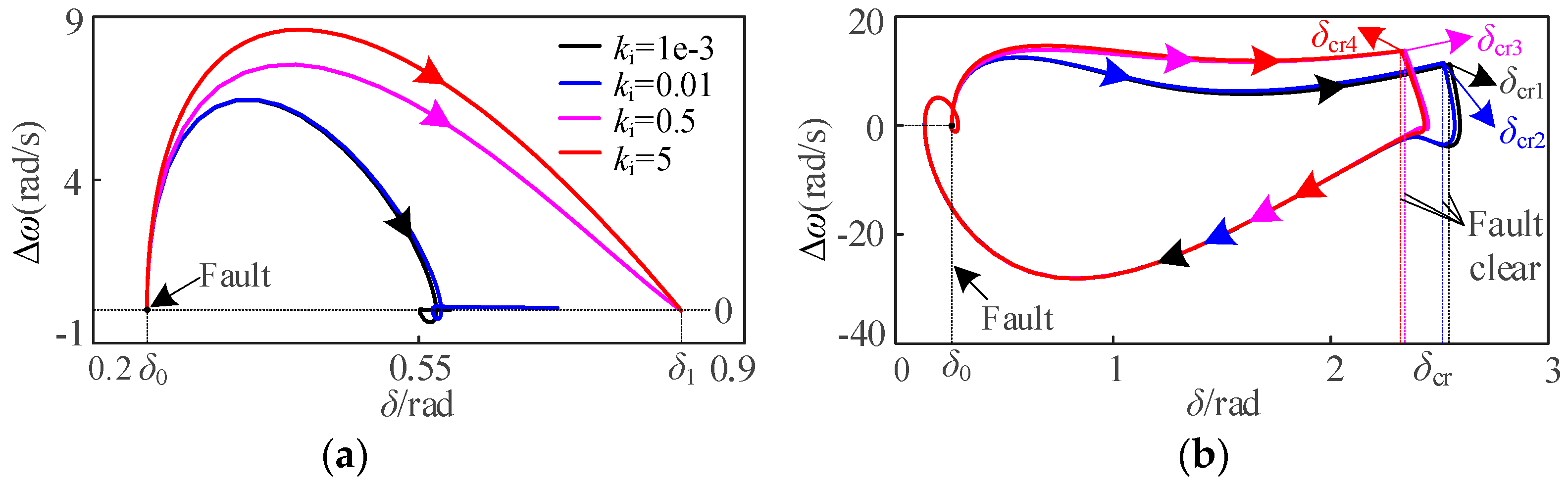
4.2.4. Influence of ki Variation on Transient Stability of Unified VSG

To analyze the influence of ki variation on the transient stability of unified VSG, taking J = 0.05, D = 3, kp = 0.01 and Dq = 160 as an example, the phase portraits of the unified VSG model with four different values of ki equal to 1 × 10⁻³, 0.01, 0.5 and 5 under faults I and II are drawn as shown in Figure 6.
It can be seen from Figure 6a that the VSGs with four different ki values are transiently stable during the fault, but with the decrease of ki, the corresponding steady-state power angle δ1 decreases. Furthermore, it can be seen from Figure 6b that under the four values of ki = 1 × 10⁻³, 0.01, 0.5 and 5, the corresponding critical clearance angle δcr gradually decreases; that is, δcr1 > δcr2 > δcr3 > δcr4, and the critical clearance time corresponding to δcr is also shorter. Moreover, the variations of δcr corresponding to ki = 0.5 and 5 are smaller than those corresponding to ki = 1 × 10⁻³ and 0.01. Therefore, under the two types of faults I and II, the smaller the ki is, the more favorable it is to enhance the transient stability of VSG, and the influence of ki on the transient stability of VSG is also independent of the fault type. At the same time, the results also show that when ki decreases to a certain extent, its influence on transient stability will be significantly weakened.

4.2.5. Influence of Dq Variation on Transient Stability of Unified VSG

To analyze the influence of Dq variation on the transient stability of unified VSG, taking J = 0.05, D = 3, kp = 0.01 and ki = 0.5 as an example, the phase portraits of the unified VSG model with four different values of ki equal to 10, 80, 160 and 300 under faults I and II are drawn as shown in Figure 7.
It can be seen from Figure 7a that only when Dq = 10, the VSG is transiently unstable during the fault, the other three VSGs are transiently stable during the fault, and the larger the Dq, the smaller the corresponding steady-state power angle. Furthermore, it can be seen from Figure 7b that under the four values of Dq = 10, 80, 160 and 300, the corresponding critical clearance angle δcr gradually increases; that is, δcr1 < δcr2 < δcr3 < δcr4, and the critical clearance time corresponding to δcr is also longer. Therefore, under the two types of faults I and II, the larger the Dq is, the more favorable it is to enhance the transient stability of VSG, and the influence of Dq on the transient stability of VSG is also independent of the fault type.
In summary, the influence of parameter changes on the transient stability of the VSG unified model is shown in Table 3. The symbols ‘↑’ and ‘↓’ denote the increase and decrease of parameters values or the enhancement and deterioration of transient stability, respectively. The ‘yes‘ means that the influence of parameter changes on transient stability depends on the fault type, and the ‘no‘ means that the influence of parameter changes on transient stability does not depend on the fault type.
From Table 3, the influence law of parameters on VSG transient stability can be obtained as follows:
(1)
For the APL of the VSG unified model, the effect of J on the transient stability of VSG is related to fault type, while the effect of D on the transient stability of VSG is independent of fault type. Specifically, the increase of J will weaken the transient stability under fault I and enhance the transient stability under fault II, and the increase of D is beneficial to enhance the transient stability.
(2)
For the RPL of the VSG unified model, the influence of parameters kp, ki and Dq on transient stability of VSG is independent of fault type. Specifically, the increase of kp and Dq is beneficial to enhance transient stability, but the increase of ki will deteriorate the transient stability.
It is worth pointing out that although the parameter influence law obtained is for the VSG unified model, the parameter influence law can be extended to heterogeneous VSG control through the parameter equivalent correspondence relationship in Table 1 and Table 2.

5. Comparative Analysis of Transient Stability of Different VSG Control Models

The APL and RPL of VSG usually introduce different action links according to the actual application scenarios, resulting in different types of APLs and RPLs. To analyze the internal mechanism of the influence of different VSG control models on transient stability, this section first analyzes the influence of three action links on transient stability, namely, primary frequency regulation, primary reactive power voltage regulation and reactive power error-free tracking, and then analyzes and compares the transient stability of VSG models with different types of APLs and RPLs.

5.1. Influence of Different Action Links on Transient Stability of VSG

For VSG control, to ensure VSC can participate in grid frequency regulation and grid voltage regulation, the primary frequency regulation link and the primary reactive voltage regulation link are usually introduced in APLs and RPLs, respectively. In addition, to accurately track the reactive power command of VSC, the reactive power error-free tracking link is also introduced in the RPL. The influence of different links on the transient stability of VSG is briefly analyzed.
(1)
Influence of primary frequency regulation on transient stability
According to the analysis of Section 3.1, the introduction of primary frequency regulation in an APL is equivalent to increasing D, and increasing D is beneficial to enhancing the transient stability of VSG. Therefore, the introduction of primary frequency regulation in an APL is beneficial to enhancing the transient stability of VSG.
(2)
Influence of primary reactive power voltage regulation on transient stability
When Dq = 0, that is, without the introduction of the primary reactive power voltage regulation link, such as the RPLs of Equations (2) and (11), and when the fault depth of the power grid is the same, the equivalent reactive power command is increased due to the effect of the primary reactive power voltage regulation link, and the increase of the reactive power command will enhance the transient stability because the VSG output voltage E is larger, resulting in a larger Pe. Therefore, the introduction of the primary reactive power voltage regulation link is beneficial to enhancing the transient stability of the VSG.
(3)
Influence of reactive power error-free tracking on transient stability
When ki = 0, that is, without the introduction of the reactive power error-free tracking link, such as the RPLs of Equations (12) and (14)–(17), and when the fault depth of the grid is the same, the output voltage E of the VSG is smaller because of the reactive power error-free tracking link, resulting in a smaller Pe. Therefore, the introduction of the reactive power error-free tracking link will weaken the transient stability of the VSG.

5.2. Influence of Different Types of APL on Transient Stability of VSG
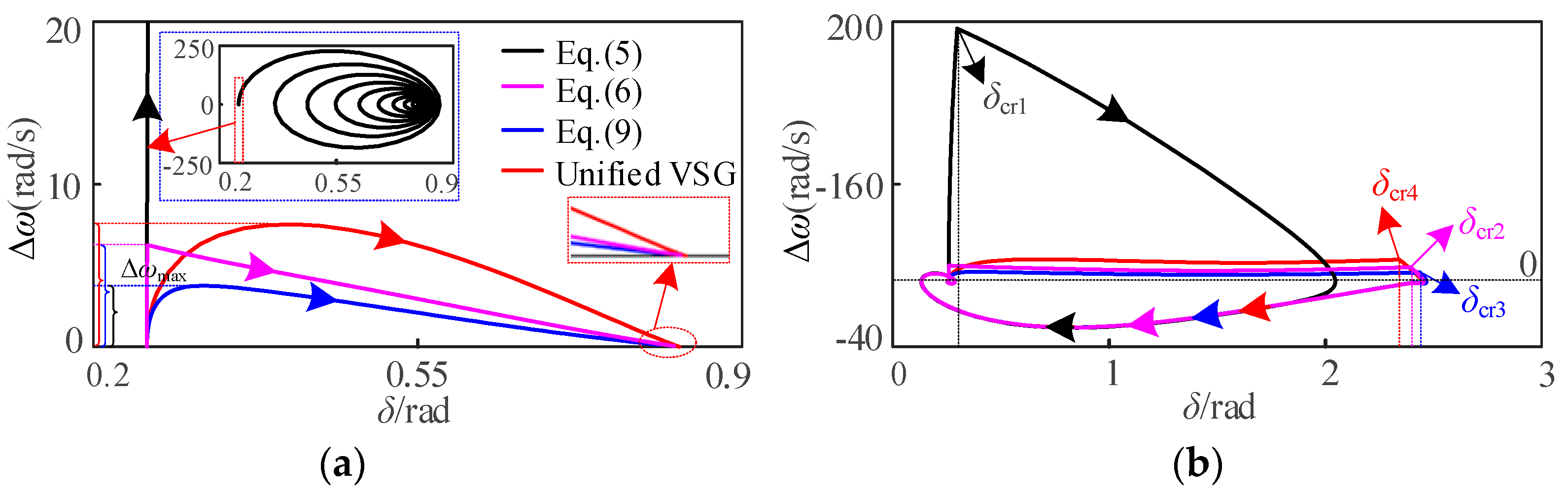
To better compare the influence of different types of APLs on the transient stability of VSG, taking J = 0.05, D = 3, kf = 1592, kp = 0.01, ki = 0.5 and Dq = 160 as examples, it is assumed that the unified VSG model is adopted before the fault. When the fault occurs, the APL of the unified VSG model is switched to the APLs of Equations (5), (6) and (9). After the fault is cleared, it is restored to the unified VSG model. The fault time t = 1 s, all parameters before and after the fault remain unchanged, and the phase portraits of different types of APLs under the two types of faults shown in Figure 8 are drawn.
It can be seen from Figure 8a that under fault I, the APLs using unified VSG, Equations (6) and (9) are transient stable within the same fault time, but the steady-state power angle δ1 and the maximum frequency deviation ∆ωmax are gradually reduced. The blue dotted box is the VSG phase trajectory using the APL of Equation (5), and it can be found that the phase trajectory is infinitely close to the steady-state equilibrium point, but due to the continuous large oscillation of the frequency (∆ωmax up to 250 rad/s), it still undergoes transient instability. Therefore, the transient stability of the four VSGs using the APLs of Equation (9), Equation (6), unified VSG and Equation (5) decreases in turn. Therefore, under fault I, the transient stability of VSG in Equation (9), Equation (6) and unified VSG model is stronger than that in Equation (5), while the transient stability of VSG in the first three active loops is difficult to compare.
It can be seen from Figure 8b that under fault II, the critical clearance angle δcr corresponding to the four VSGs using the APLs of Equation (9), Equation (6), unified VSG and Equation (5) gradually decreases; that is, δcr3 = 2.4365 rad > δcr2 = 2.3945 rad > δcr4 = 2.3405 rad > δcr1 = 0.2972 rad, which also indicates that the transient stability decreases in turn. In addition, the transient stability of Equation (9) is stronger than that in Equation (6), and the transient stability of Equation (6) is stronger than that in unified VSG.
It is worth noting that the transient stability of Equation (9) is stronger than that of Equation (6) because the APL of Equation (9) is in torque form, while the APL of Equation (6) is in power form. The inertia and damping of the torque form are larger than that of the power form. Under fault II, the increase of inertia and damping will improve the transient stability. The transient stability of VSG in the APL of Equation (6) is stronger than that of unified VSG, which is because the value of primary frequency modulation coefficient kf in Equation (6) in this paper is larger. If kf is smaller, the transient stability of the two is the opposite.
By comparing the unified VSG with the phase trajectories of Equation (9), Equation (5) and Equation (6), it can be found that the transient stability of the former is weaker than that of the latter, which are due to the introduction of the primary frequency regulation link in the APLs of Equations (9) and (6), and the introduction of the primary frequency modulation link is equivalent to increasing D, which is conducive to improving the transient stability. Therefore, the transient stability of the two APLs VSG of Equations (9) and (6) is stronger than that of the unified VSG and Equation (5).
According to Table 4, the transient stability and fault adaptability rules of different types of VSG are summarized as follows:
(1)
For the APL VSG of the power type, the transient stability and fault adaptability of the APL VSG with the primary frequency regulation link are stronger than those without the primary frequency regulation link. Its influence on transient stability is independent of fault type because introducing the primary frequency modulation link is equivalent to increasing D, and the influence of D on transient stability is independent of fault type.
(2)
For the APL VSG of torque type, the transient stability and fault adaptability of APL VSG with the primary frequency regulation link are stronger than those without the primary frequency regulation link, and its influence on transient stability is independent of fault type.
(3)
The transient stability and fault adaptability of VSG with different APL types depend not only on the primary frequency regulation link but also on the APL type and are related to the fault type because different APL types lead to different equivalent inertia and damping coefficients.

5.3. Influence of Different Types of RPL on Transient Stability of VSG

According to the analysis in Section 3.2, when ki = 0, Equations (2) and (13) are equivalent, and the difference is only in whether there is a primary voltage regulation link; when kp = 0, Equation (14) is equivalent to Equations (15)–(17), so Equations (13) and (14) are selected as the representatives for research. To better compare the influence of different types of RPLs on the transient stability of VSG, taking J = 0.05, D = 3, kp = 0.01, ki = 0.5 and Dq = 160 as examples, it is assumed that the unified VSG model is adopted before the fault. When the fault occurs, the RPL of the unified VSG model is switched to the RPLs of Equations (11), (13) and (14). After the fault is cleared, it is restored to the unified VSG model. The fault time t =1 s, all parameters before and after the fault remain unchanged, and the phase portraits of the different types of RPLs under two types of faults shown in Figure 9 are drawn.
It can be seen from Figure 9a that under fault I, the VSGs of the RPL using Equation (14), unified VSG and Equation (13) are all transient stable within the same fault time, and the maximum frequency deviation ∆ωmax gradually decreases, but the steady-state power angle δ1 is the smallest in Equation (13), and the VSG of RPL using Equation (11) is transient unstable. The results show that the transient stability of the VSG of an RPL using Equation (13) is the best, while that of the VSG of an RPL using Equation (11) is the worst. In addition, the transient stability of the VSG using unified VSG is the same as that of the RPL of Equation (14), but the former’s Δωmax is smaller.
It can be seen from Figure 9b that under fault II, the critical clearance angle δcr corresponding to the four VSGs using the APL of Equation (13), unified VSG, Equation (14) and Equation (11) gradually decreases; that is, δcr1 = 2.5423 rad > δcr4 = 2.3405 rad > δcr3 = 2.3325 rad > δcr2 = 2.0772 rad, which indicates that the transient stability decreases in turn. Among them, the VSG transient stability of the RPL using Equation (13) is the best. The VSG transient stability of the RPL with Equation (11) is the worst, while the VSG transient stability of the RPL with unified VSG is slightly stronger than that in Equation (14).
It is worth noting that the transient stability of unified VSG is slightly stronger than Equation (14) because the proportional coefficient kp of the reactive power error-free tracking link of the former is not equal to 0, while kp of the latter is 0. Since the larger kp is, the stronger the transient stability is, the transient stability of unified VSG is stronger than that in Equation (14), and the fault adaptability is better.
Further, due to Equations (14)–(17) being equivalent, and in the case where the parameters correspond to the same, the transient stability of Equations (14)–(17) is the same; therefore, the transient stability of unified VSG is also stronger than that of Equations (15)–(17), and the fault adaptability is better. In practice, the parameters of Equations (14)–(17) are not necessarily equal. In this case, the transient stability of Equations (14)–(17) can be judged according to the influence law of parameters on transient stability and parameter size in Table 3, which is not repeated here.
By comparing the phase trajectory of the unified VSG with that of Equation (11), it can be found that the transient stability of the former is stronger than that of the latter. This is because the RPL of the unified VSG introduces the primary reactive voltage regulation link, and the larger the reactive voltage regulation link Dq is, the more conducive it is to improving transient stability. Therefore, the introduction of the primary reactive voltage regulation link is conducive to improving transient stability, and the VSG with the RPL of the unified VSG model has stronger transient stability. In addition, by comparing the phase trajectory of the unified VSG with that of Equation (13), it can be found that the transient stability of the former is weaker than that of the latter. This is because the integral coefficient ki of the reactive power error-free tracking link of the former is not equal to 0, while ki of the latter is 0. Since the smaller ki is, the stronger the transient stability is, the transient stability of the unified VSG is stronger than that of Equation (13), and the fault adaptability is better.
Therefore, for the seven types of RPL VSG, namely, Equation (11), unified VSG, Equations (13)–(17), their transient stability is from strong to weak as follows: Equation (13), unified VSG, Equations (14)–(17), and Equation (11). The simulation results prove the correctness of the analysis on the influence of parameters on transient stability.
According to Table 5, the transient stability and fault adaptability rules of different types of VSG are summarized as follows:
(1)
The influence of VSG on transient stability of different types of RPLs is independent of fault type; that is to say, the influence of different types of RPLs on transient stability is consistent under two types of faults.
(2)
For VSG with different types of RPLs, introducing primary reactive voltage regulation is beneficial to improve transient stability, while introducing a reactive power error-free tracking link is dependent on kp and ki.
(3)
For VSG with the same type of RPL, its transient stability is only determined by the corresponding RPL parameters, and the transient stability of VSG can be compared only according to the influence law of RPL parameters on transient stability; for VSG with different types, its transient stability is not only determined by RPL parameters, but also by the primary reactive voltage regulation link and reactive power error-free tracking link in VSG. Under the conditions of the same action link, a transient stability comparison can be carried out according to the parameters.

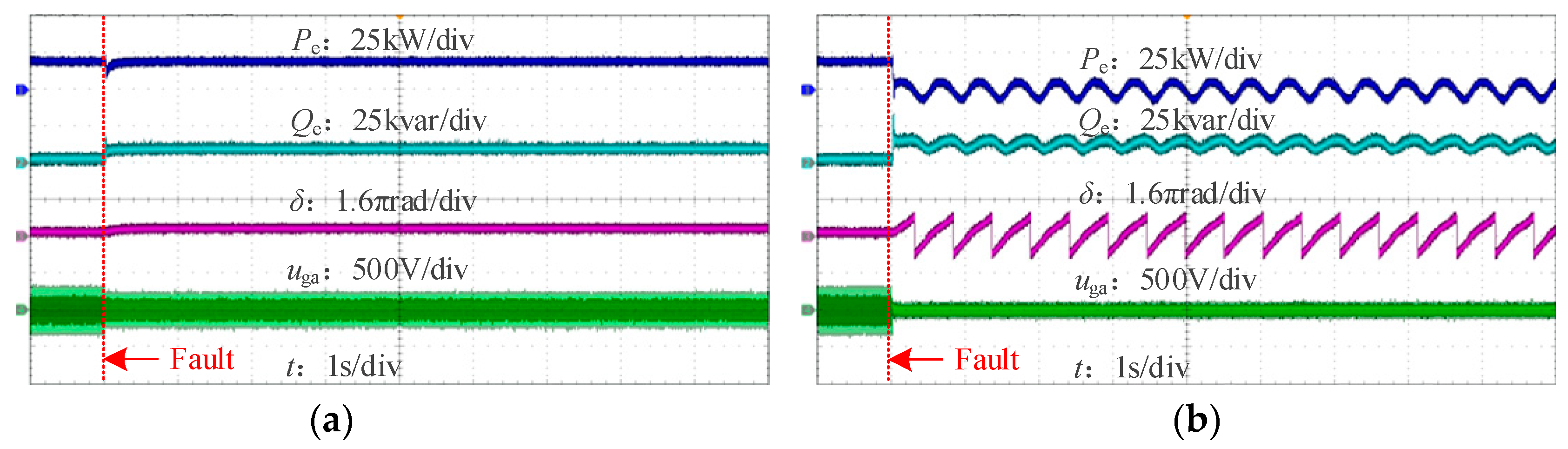
6. Experimental Verification

To verify the correctness of the VSG unified model and the transient stability impact analysis, this paper uses the RT-LAB hardware-in-the-loop experimental platform to build the main circuit and control model shown in Figure 1 for experimental verification under two types of faults. The main circuit model and the control model are implemented in the RT-LAB real-time simulator and the DSP28335 controller, respectively. The main parameters of the experiment are shown in Table 6.
Figure 10 shows the experimental waveforms of the unified VSG model under two types of faults. Figure 10a shows that the unified VSG model is transient stable under fault I when k = 0.7; Figure 10b shows that the unified VSG model is transient unstable under fault II when k = 0.2. The experimental results are completely consistent with the transient stability of the unified VSG model under the two types of faults described in Section 4 and Section 5, which verifies the correctness of the theoretical analysis.
To verify the influence of the parameters of the unified VSG control model on its transient stability, the experimental waveforms of the influence of J, D, kp, ki and Dq on the transient stability of the unified VSG model are given respectively under the condition that other parameters are kept unchanged, as shown in Figure 11. Comparing Figure 11a with Figure 10a, it can be clearly seen that VSG changes from transient stability to transient instability when J increases from 0.05 kg/m2 to 10 kg/m2 under fault I. The experimental waveforms show that increasing J deteriorates the transient stability of VSG under fault I, which is completely consistent with the simulation results of Figure 3a. Comparing Figure 11b with Figure 10b, it can be clearly seen that when J increases from 0.05 k/m2 to 1 kg/m2 under fault II, the VSG instability time is prolonged; in other words, the critical clearing time is prolonged and the transient stability is enhanced. The experimental waveforms show that increasing J enhances the transient stability of VSG under fault II, which is completely consistent with the simulation results of Figure 3b. Comparing Figure 11c with Figure 10b, it can be clearly seen that when D increases from 5 N.m.s/rad to 20 N.m.s/rad under fault II, the instability time is obviously prolonged, and the transient stability is enhanced. The experimental waveforms show that increasing D enhances the transient stability of VSG under fault II, which is completely consistent with the simulation results of Figure 4b.
Further, comparing Figure 11d with Figure 10b, when kp increases from 0.001 to 0.0018 under fault II, the instability time of VSG is prolonged and the transient stability is enhanced. Experimental waveforms show that increasing kp enhances the transient stability of VSG under fault II, which is completely consistent with the simulation results of Figure 5b. Comparing Figure 11e with Figure 10b, when ki is reduced from 0.05 to 5×10⁻⁷ under fault II, the instability time of VSG is slightly prolonged and the transient stability is enhanced. Experimental waveforms show that reducing ki enhances the transient stability of VSG under fault II, but its influence on the transient stability of VSG is smaller than that of other parameters, which is completely consistent with the simulation results in Figure 6b. Comparing Figure 11f with Figure 10b, when Dq increases from 160 to 320 under fault II, the instability time of VSG is prolonged and the transient stability is enhanced. Experimental waveforms show that increasing Dq enhances the transient stability of VSG under fault II, which is completely consistent with the simulation results of Figure 7b.
In addition, to verify the influence of different links on the transient stability of unified VSG, the experimental waveforms of the influence of the primary frequency regulation link, primary reactive power voltage regulation link and reactive power error-free tracking link on the transient stability of VSG are given respectively, as shown in Figure 12. Comparing Figure 12a with Figure 10b, when kf increases from 0 to 3 kW/rad s−1 during the fault period, in other words, when the primary frequency regulation link is introduced during the fault, the instability time of VSG is prolonged and transient stability is enhanced. Experimental waveforms show that the primary frequency regulation link enhances the transient stability of VSG, which verifies the correctness of the theoretical analysis in Section 5.1. Comparing Figure 12b with Figure 10b, the transient stability of VSG is enhanced when ki decreases from 0.05 to 0 during the fault; that is, when there is no reactive power error-free tracking link during the fault. Experimental waveforms show that the reactive power error-free tracking link deteriorates transient stability of VSG, verifying the correctness of the theoretical analysis in Section 5.1. Comparing Figure 12c with Figure 10b, when Dq decreases from 160 to 0 during the fault period, that is, when there is no primary reactive power voltage regulation link during the fault, transient instability occurs and transient stability of VSG is deteriorated. Experimental waveforms show that the primary reactive power voltage regulation link enhances transient stability of VSG, which verifies the correctness of the theoretical analysis in Section 5.1.
Since the differences in the influence of the VSG model with different power loops on transient stability is essentially caused by the action of three different links, the transient stability and fault adaptability of the VSG model of different power loops can be deduced according to the experimental results in Figure 12. It can be seen from the above experimental results that the simulation results are completely consistent with the experimental results, which verifies the correctness of the theoretical analysis again.

7. Conclusions

Focusing on the problems that it is difficult to compare the transient stability of different VSG control models and that the evolution characteristics between models and the influence mechanism of transient stability are not clear, a unified VSG model is proposed in this paper. Based on this model, the transient stability of different VSG control models is comprehensively compared and analyzed and verified by experiments. The following important conclusions are obtained.
(1)
The evolution characteristics of APLs and RPLs controlled by mainstream VSGs are mainly represented by whether primary frequency modulation is introduced into APLs and reactive voltage regulation and reactive power error-free tracking are introduced into RPLs, and these three links are also the fundamental reasons for the different transient stability of different VSG control models.
(2)
For the unified VSG control model, all the control parameters are independent of fault type except the influence of J on transient stability.
(3)
For different VSG control models, the transient stability of VSG can be enhanced by introducing primary frequency regulation and primary reactive power voltage regulation, while the transient stability of VSG can be deteriorated by introducing reactive power error-free tracking. In addition, the torque-type VSG has stronger transient stability and stronger fault adaptability than the power-type VSG.
(4)
The method and principle for comparing the transient stability of different types of APL VSG are given. Under the same RPL conditions, for APL VSGs of the same form, the transient stability of the APL VSG with the primary frequency modulation link is stronger. For APL VSGs of different forms, it is necessary to consider the primary frequency regulation link, APL form and fault type when comparing transient stability and fault adaptability.
(5)
The method and principle for comparing the transient stability of different types of RPL VSG are given. Under the same RPL conditions, for different types of RPL VSGs, the transient stability of the RPL with the primary reactive voltage regulation link is stronger. For RPL VSGs of the same form, its transient stability is only determined by the RPL parameters; while for VSGs of different forms, its transient stability is not only determined by the RPL parameters but also by the primary reactive voltage regulation link and reactive power error-free tracking link in the VSG.

Author Contributions

Conceptualization and Methodology, W.Y.; Validation, M.L. and C.W.; Investigation, R.Z. and J.L.; Writing-original draft preparation, C.W.; Writing-Review and Editing, M.L., R.Z., J.L. and W.Y.; Supervision, Y.C. and M.L., Project administration, M.L., R.Z. and Y.C. All authors have read and agreed to the published version of the manuscript.

Funding

This research was supported by Science and Technology Projects of Southern Power Grid Co., Ltd. (Grant No. 031200KK52222026, GDKJXM20222220).

Data Availability Statement

The data presented in this study are available on request from the corresponding author. The data are not publicly available due to project data restriction.

Conflicts of Interest

Authors Ruifeng Zhao and Jiangang Lu were employed by the Electric Power Dispatching Control Center of Guangdong Power Grid Co., Ltd. Author Yizhe Chen was employed by Zhaoqing Power Supply Bureau of Guangdong Power Grid Co., Ltd. The remaining authors declare that the research was conducted in the absence of any commercial or financial relationships that could be construed as a potential conflict of interest.

References

  1. Luo, C.; Liu, T.; Wang, X.; Ma, X. Design-Oriented Analysis of DC-Link Voltage Control for Transient Stability of Grid-Forming Inverters. IEEE Trans. Ind. Electron. 2024, 71, 3698–3707. [Google Scholar] [CrossRef]
  2. Tu, C.; Yang, W.; Xiao, F.; Guo, Q.; He, X. Transient power angle stability control method of VSG considering fault current limitation. Electr. Power Autom. Equip. 2023, 43, 55–62. [Google Scholar]
  3. Ge, P.; Tu, C.; Xiao, F.; Guo, Q.; Gao, J. Design-Oriented Analysis and Transient Stability Enhancement Control for a Virtual Synchronous Generator. IEEE Trans. Ind. Electron. 2023, 70, 2675–2684. [Google Scholar] [CrossRef]
  4. Hu, X.; Li, Z.; Pan, C.; Li, H.; Liang, Y. An Adaptive Virtual-Impedance-Based Current-Limiting Method with the Functionality of Transient Stability Enhancement for Grid-Forming Converter. Electronics 2024, 13, 2750. [Google Scholar] [CrossRef]
  5. Lou, G.; Yang, Q.; Gu, W.; Zhang, J. An Improved Control Strategy of Virtual Synchronous Generator Under Symmetrical Grid Voltage Sag. Int. J. Electr. Power Energy Syst. 2020, 121, 106093. [Google Scholar] [CrossRef]
  6. Zhao, F.; Shuai, Z.; Huang, W.; Shen, Y.; Shen, Z.J.; Shen, C. A Unified Model of Voltage-Controlled Inverter for Transient Angle Stability Analysis. IEEE Trans. Power Deliv. 2022, 37, 2275–2288. [Google Scholar] [CrossRef]
  7. Yang, W.; Tu, C.; Xiao, F.; Guo, Q. A combined regulation method of transient power angle stability control and fault current suppression for VSG. Int. J. Electr. Power Energy Syst. 2024, 156, 109702. [Google Scholar] [CrossRef]
  8. Shuai, Z.K.; Huang, W.; Shen, C.; Ge, J.; Shen, Z.J. Characteristics and restraining method of fast transient inrush fault currents in synchronverters. IEEE Trans. Ind. Electron. 2017, 64, 7487–7497. [Google Scholar] [CrossRef]
  9. Li, Z.; Chan, K.W.; Hu, J.; Or, S.W. An adaptive fault ride-through scheme for grid-forming inverters under asymmetrical grid faults. IEEE Trans. Ind. Electron. 2022, 69, 12912–12923. [Google Scholar] [CrossRef]
  10. Koiwa, K.; Inoo, K.; Zanma, T.; Liu, K.-Z. Virtual voltage control of VSG for overcurrent suppression under symmetrical and asymmetrical voltage dips. IEEE Trans. Ind. Electron. 2022, 69, 11177–11186. [Google Scholar] [CrossRef]
  11. Li, M.; Huang, W.; Tai, N.; Yang, L.; Duan, D.; Ma, Z. A Dual-Adaptivity Inertia Control Strategy for Virtual Synchronous Generator. IEEE Trans. Power Syst. 2020, 35, 594–604. [Google Scholar] [CrossRef]
  12. Guo, J.; Chen, Y.D.; Wang, L.; Wu, W.H.; Wang, X.Y. Impedance analysis and stabilization of virtual synchronous generators with different DC-link voltage controllers under weak grid. IEEE Trans. Power Electron. 2021, 36, 11397–11408. [Google Scholar] [CrossRef]
  13. Sun, K.; Yao, W.; Wen, J.; Jiang, L. A Two-Stage Simultaneous Control Scheme for the Transient Angle Stability of VSG Considering Current Limitation and Voltage Support. IEEE Trans. Power Syst. 2022, 37, 2137–2150. [Google Scholar] [CrossRef]
  14. Xiong, X.; Wu, C.; Blaabjerg, F. An Improved Synchronization Stability Method of Virtual Synchronous Generators Based on Frequency Feedforward on Reactive Power Control Loop. IEEE Trans. Power Electron. 2021, 36, 9136–9148. [Google Scholar] [CrossRef]
  15. Pan, D.; Wang, X.; Liu, F.; Shi, R. Transient Stability of Voltage-Source Converters with Grid-Forming Control: A Design-Oriented Study. IEEE J. Emerg. Sel. Top. Power Electron. 2020, 8, 1019–1033. [Google Scholar] [CrossRef]
  16. Huang, L.; Xin, H.H.; Li, Z.Y.; Ju, P.; Yuan, H. Grid-Synchronization stability analysis and loop shaping for PLL-Based power converters with different reactive power control. IEEE Trans. Smart Grid 2020, 11, 501–516. [Google Scholar] [CrossRef]
  17. Shuai, Z.; Shen, C.; Liu, X.; Li, Z.; Shen, Z. Transient Angle Stability of Virtual Synchronous Generators Using Lyapunov’s Direct Method. IEEE Trans. Smart Grid 2019, 10, 4648–4661. [Google Scholar] [CrossRef]
  18. Pan, D.; Wang, X.; Liu, F.; Shi, R. Transient stability impact of reactive power control on grid-connected converters. In Proceedings of the 2019 IEEE Energy Conversion Congress and Exposition (ECCE), Baltimore, MD, USA, 29 September–3 October 2019; pp. 4311–4316. [Google Scholar]
  19. Chen, M.; Zhou, D.; Blaabjerg, F. Enhanced Transient Angle Stability Control of Grid-Forming Converter Based on Virtual Synchronous Generator. IEEE Trans. Ind. Electron. 2022, 69, 9133–9144. [Google Scholar] [CrossRef]
  20. Zhang, Y.X.; Chen, Y.C.; Liu, K.X.; Han, Y. Influence of control parameters on synchronization stability of virtual synchronous generator. Arch. Electr. Eng. 2022, 71, 811–828. [Google Scholar]
  21. Luo, S.; Han, H.; Chen, S.; Shi, G.; Ou, J.; Luo, Z. A Mode Switching Method for Transient Stability Enhancement of VSG. In Proceedings of the 2022 IEEE Energy Conversion Congress and Exposition (ECCE), Detroit, MI, USA, 9–13 October 2022; pp. 1–5. [Google Scholar]
  22. Oureilidis, K.O.; Demoulias, C.S. A fault clearing method in converter-dominated microgrids with conventional protection means. IEEE Trans. Power Electron. 2016, 31, 4628–4640. [Google Scholar] [CrossRef]
  23. Kuang, Y.; Xu, Q. A Current-Limiting Scheme for Voltage-Controlled Inverter Using Instantaneous Current to Generate Virtual Impedance. IEEE J. Emerg. Sel. Top. Circuits Syst. 2023, 13, 524–535. [Google Scholar]
  24. Qoria, T.; Gruson, F.; Colas, F.; Kestelyn, X.; Guillaud, X. Current limiting algorithms and transient stability analysis of grid-forming VSCs. Electr. Power Syst. Res. 2020, 189, 106726. [Google Scholar] [CrossRef]
  25. Han, X.; Deng, C.P.; Dai, L.Y.; Zheng, M.Y.; Ling, Z.B. VSG Transient Power Angle Stabilization Strategy Considering Current Limiting. In Proceedings of the 2022 Asian Conference on Frontiers of Power and Energy (ACFPE), Chengdu, China, 21–23 October 2022; pp. 472–477. [Google Scholar]
  26. Luo, C.; Chen, Y.D.; Xu, Y.C.; Wang, Z.L.; Liao, S.H.; Xie, Z.W. Two-Stage Transient Control for VSG Considering Fault Current Limitation and Transient Angle Stability. IEEE Trans. Ind. Electron. 2024, 71, 7169–7179. [Google Scholar] [CrossRef]
  27. Zhang, G.; Zhan, L.; Wang, J.; Ke, X.; Ren, C.; Nian, H. Effect of Different Reactive Power Control Structures of Voltage Source Converters on Transient Stability. In Proceedings of the 2023 IEEE 6th International Electrical and Energy Conference (CIEEC), Hefei, China, 12–14 May 2023; pp. 472–477. [Google Scholar]
  28. Zhao, F.; Shuai, Z.; Shen, C.; Cheng, H.; Shen, Y. Comparison of Transient Angle Stability Between Different Virtual Synchronous Generators. In Proceedings of the 2019 IEEE 3rd Conference on Energy Internet and Energy System Integration (EI2), Changsha, China, 8–10 November 2019; pp. 2529–2533. [Google Scholar]
  29. Wu, W.H.; Zhou, L.M.; Chen, Y.D.; Luo, A.; Zhou, X.P.; He, Z.X.; Yang, L.; Liu, J.M. Stability Comparison and Analysis Between the Virtual Synchronous Generator and the Traditional Grid-connected Inverter in the View of Sequence Impedance. Proc. CSEE 2019, 39, 1411–1420. (In Chinese) [Google Scholar]
  30. Liu, J.; Miura, Y.; Ise, T. Fixed-Parameter Damping Methods of Virtual Synchronous Generator Control Using State Feedback. IEEE Access 2019, 7, 99177–99190. [Google Scholar] [CrossRef]
  31. Meng, X.; Liu, J.; Liu, Z. A Generalized Droop Control for Grid-Supporting Inverter Based on Comparison Between Traditional Droop Control and Virtual Synchronous Generator Control. IEEE Trans. Power Electron. 2019, 34, 5416–5438. [Google Scholar] [CrossRef]
  32. Tu, C.M.; Xie, W.J.; Xiao, F.; Lan, Z. Influence Analysis of Control Parameters of Parallel System with Multiple Virtual Synchronous Generators on Stability. Autom. Electr. Power Syst. 2020, 44, 77–86. (In Chinese) [Google Scholar]
  33. Meng, X.; Liu, Z.; Liu, J.; Wang, S.K.; Liu, B.X.; An, R.H. Comparison between inverters based on virtual synchronous generator and droop control. In Proceedings of the 2017 IEEE Energy Conversion Congress and Exposition (ECCE), Cincinnati, OH, USA, 1–5 October 2017; pp. 4077–4084. [Google Scholar]
  34. Lv, Z.P.; Sheng, W.X.; Zhong, Q.C.; Liu, H.T.; Zheng, Z.; Yang, L.; Lan, L. Virtual Synchronous Generator and Its Applications in Micro-grid. Proc. CSEE 2014, 34, 2591–2603. (In Chinese) [Google Scholar]
  35. Wen, T.; Zou, X.; Zhu, D.; Guo, X.; Li, P.; Kang, Y. Comprehensive perspective on virtual inductor for improved power decoupling of virtual synchronous generator control. IET Renew. Power Gener. 2020, 14, 485–494. [Google Scholar] [CrossRef]
  36. Cheema, K.M. A comprehensive review of virtual synchronous generator. Int. J. Electr. Power Energy Syst. 2020, 120, 106006. [Google Scholar] [CrossRef]
  37. Tu, C.M.; Lan, Z.; Xiao, F.; Shuai, Z.K.; Meng, Y. Study on Cascaded H-bridge Photovoltaic Power Systems with Synchronous Generator Characteristics. Proc. CSEE 2017, 37, 433–443. (In Chinese) [Google Scholar]
Figure 1. Main circuit and typical VSG control model.
Electronics 13 03560 g001
Figure 2. Evolution diagram of different types of RPLs in VSG.
Electronics 13 03560 g002
Figure 3. Phase portraits of the unified VSG with different J under two types of faults. (a) Fault I; (b) Fault II.
Electronics 13 03560 g003
Figure 4. Phase portraits of the unified VSG with different D under two types of faults. (a) Fault I; (b) Fault II.
Electronics 13 03560 g004
Figure 5. Phase portraits of the unified VSG with different kp under two types of faults. (a) Fault I; (b) Fault II.
Electronics 13 03560 g005
Figure 6. Phase portraits of the unified VSG with different ki under two types of faults. (a) Fault I; (b) Fault II.
Electronics 13 03560 g006
Figure 7. Phase portraits of the unified VSG with different Dq under two types of faults. (a) Fault I; (b) Fault II.
Electronics 13 03560 g007
Figure 8. Phase portraits of the VSG with different types of APLs under two types of faults. (a) Fault I; (b) Fault II.
Electronics 13 03560 g008
Figure 9. Phase portraits of the VSG with different types of RPLs under two types of faults. (a) Fault I; (b) Fault II.
Electronics 13 03560 g009
Figure 10. Experimental waveforms of unified VSG control model under two types of faults. (a) Fault I (k = 0.7); (b) Fault II (k = 0.2).
Electronics 13 03560 g010
Figure 11. Experimental waveforms of the influence of various unified VSG control parameters on its transient stability. (a) J increases from 0.05 to 10 under fault I; (b) J increases from 0.05 to 1 under fault II; (c) D increases from 5 to 20 under fault II; (d) kp increases from 1 × 10⁻³ to 1.8 × 10⁻³ under fault II; (e) ki decreases from 0.05 to 5 × 10⁻⁷ under fault II; (f) Dq increases from 160 to 320 under fault II.
Electronics 13 03560 g011
Figure 12. Experimental waveforms of the influence of different links on the transient stability of unified VSG. (a) kf increases from 0 to 3 under fault II; (b) ki decreases from 0.05 to 0 under fault II; (c) Dq decreases from 160 to 0 under fault I.
Electronics 13 03560 g012
Table 1. Parameter equivalent correspondence between the VSG unified APL model and the other five types of models.
APL TypeJD
Equation (1)JeqDeq
Equation (4)JeqDeq
Equation (5)Jeqω0Deqω0
Equation (6)Jeqω0Deqω0-kf
Equation (9)Jeqω0Deq-kf/ω0
Equation (10)JeqDeq
Table 2. Parameter equivalent correspondence between the VSG unified RPL model and the other seven types of models.
RPL TypekpkiDqJqKkvkq
Equation (2)kq00---kp
Equation (11)kpki0----
Equation (12)kpkiDq----
Equation (13)kq0---kpDqkp
Equation (14)01/JqDq1/ki---
Equation (15)01/JqDq1/ki---
Equation (16)01/Kkv-1/kiDq-
Equation (17)01/Kkv-1/kiDq-
Table 3. Influence of parameter changes on the transient stability of VSG unified model.
Parameter ChangesTransient Stability under Fault ITransient Stability
under Fault II
Whether It Depends on
the Fault Type Types
Jyes
Dno
kpno
kino
Dqno
Table 4. Influence of different types of APLs on the transient stability of VSG.
APL TypeCharacteristicsTransient Stability
under Faults I and II
Fault Adaptability
Equation (5)Power type, without primary frequency modulationweakweak
Unified VSGTorque type, without primary frequency modulationstrongstrong
Equation (6)Power type, with primary frequency modulationstrongerstronger
Equation (9)Torque type, with primary frequency modulationstrongerstronger
Table 5. Influence of different types of RPLs on the transient stability of VSG.
RPL TypeCharacteristicsTransient Stability
under Faults I and II
Fault Adaptability
Equation (2)ki = 0, without primary reactive power voltage regulation and
reactive power error-free tracking
strongerstronger
Equation (13)
Equation (11)only with reactive power error-free trackingweakweak
Unified VSGwith primary reactive power
voltage regulation and
reactive power error-free tracking
strongstrong
Equation (14)kp = 0, with primary reactive power voltage regulation and
reactive power error-free tracking
strongstrong
Equation (15)
Equation (16)
Equation (17)
Table 6. Influence of different types of APL on the transient stability of VSG.
ParametersValueParametersValue
Pm20 kWω0314 rad/s
Qm5 kvarTs1 × 10−5 s
Udc800 VJ0.05 kg/m2
UgN311 VD5 N.m.s/rad
U0311 Vkq0.001 V/kvar
Lf3 mHkp0.001
Cf40 μFki0.05
Lg11.5 mHDq160 kvar/V
Disclaimer/Publisher’s Note: The statements, opinions and data contained in all publications are solely those of the individual author(s) and contributor(s) and not of MDPI and/or the editor(s). MDPI and/or the editor(s) disclaim responsibility for any injury to people or property resulting from any ideas, methods, instructions or products referred to in the content.

