Article

Research on Space Operation Control of Air Float Satellite Simulator Based on Constraints Aware Particle Filtering-Nonlinear Model Predictive Control

1
School of Mechanical Engineering, Nanjing University of Science & Technology, Nanjing 210094, China
2
Key Laboratory of Special Engine Technology, Ministry of Education, Nanjing University of Science and Technology, Nanjing 210094, China
*
Author to whom correspondence should be addressed.
Electronics 2024, 13(17), 3571; https://doi.org/10.3390/electronics13173571
Submission received: 19 August 2024 / Revised: 5 September 2024 / Accepted: 6 September 2024 / Published: 8 September 2024

Abstract

:
This paper addresses the challenges of close proximity operations, such as rendezvous, docking, and fly-around maneuvers for micro/nano satellites, which require high control precision under the low power and limited computational capabilities of spacecraft. Firstly, a three-degree-of-freedom air float simulator platform is designed for ground-based experiments. Subsequently, model predictive controllers based on constraints aware of particle filtering (CAPF-NMPC) are developed for executing operations such as approach, fly-around, and docking maneuvers. The results validate the effectiveness of the experimental system, demonstrating position control accuracy less than 0.03 m and attitude control accuracy less than 3°, maintaining lower computational resource consumption. This study offers a practical solution for the onboard deployment of optimized control algorithms, highlighting significant value for further engineering applications.

1. Introduction

The availability of space orbital resources is becoming increasingly limited, and micro/nano satellites are being utilized in a multitude of fields, including communication [1,2,3], remote sensing [4,5,6], and navigation [7], due to their cost-effectiveness, rapid development cycle, and high flexibility [8]. These attributes are attributed to their high adaptability and flexibility in responding to diverse missions. The advantage of group batch production allows micro/nano satellites to rapidly achieve constellation network operations, thereby significantly reducing the cycle time of the entire satellite system. This enables rapid improvements in global coverage capability, which is a crucial aspect of future spacecraft development. Furthermore, as satellite maneuvering capabilities continue to improve, the complexity of space maneuvering tasks is also increasing. These tasks include but are not limited to, orbit maintenance [9], adjustment [10], attitude stabilization [11,12], rendezvous and docking [13], flight formation [14,15], and orbital gaming [16]. In order to meet the demanding specifications of space missions, the investigation of orbital autonomy and ground simulations has become a crucial endeavor. This not only enhances the capacity of microsatellites to undertake intricate operations in space but also presents a potential avenue for streamlining the development and deployment of satellite systems. Furthermore, it offers a reliable technical means to reduce development costs and technical risks, thereby enhancing the ability of micro/nano satellites to perform complex tasks in space.
Micro/nano satellites frequently encounter a multitude of challenges when undertaking missions such as approach, fly-by gaze, and intersection docking. For instance, data regarding the target satellite may be scarce, necessitating the precise tracking of the line-of-sight angle through the use of vision cameras [17], LIDAR [18], and other techniques. Furthermore, larger attachments or dynamic obstacles, such as solar sail panels or space debris, may be encountered during the docking process, which can affect safety during rendezvous and docking. As a result, multiple constraints must be considered during mission planning and execution. Furthermore, precision is a critical factor in the docking process. Even slight positional deviations can result in docking failures or collisions, while speed deviations also impact the success rate of docking. If the speed is insufficient, the docking mechanism cannot be locked, and if the speed is excessive, the components may be damaged.
Theoretical challenges in rendezvous and docking control are further complicated by practical engineering difficulties, including model uncertainties, external disturbances, and communication disruptions during docking with cooperative targets. Additional constraints, such as thruster saturation, sensor noise, and limited onboard computational resources, place stringent demands on the robustness and real-time computational performance of control algorithms. Consequently, the development of efficient and accurate optimal control strategies with limited computational resources is a pivotal challenge in this field.
A significant challenge in the field of spacecraft rendezvous and docking control is the deployment of high-performance and optimal algorithms on an onboard platform with limited computational resources. This presents a fundamental conflict between algorithm complexity and computational consumption and between algorithm performance and optimality. In the early stages of rendezvous and docking, classical control methods were frequently employed, including the glideslope method [19], sliding mode [20], and artificial potential function [21]. While these methods offer faster computational speeds, they also present notable drawbacks and are not as optimal as optimal control.
The method of the optimal control strategy can be formulated as a nonlinear optimization problem. However, real space exhibits a high degree of nonlinearity, which makes it more challenging to model and solve the optimization problem. Therefore, it is typically linearized in its state space before solving. For example, optimal energy guidance and flyby methods for tracking spacecraft and rotating target spacecraft have been studied in the literature [22]. Furthermore, model predictive control has garnered increasing attention for its efficacy in addressing multiple constraints, leading to its broader adoption in rendezvous and docking operations [23,24,25]. Kaikai Dong [26] proposed a tubular robust output feedback-based model predictive control (TRMPC) method for the autonomous rendezvous and docking of tracking spacecraft in near-circular orbits and subsequently developed a new MPC framework that took into account control saturation, velocity constraints, and collision avoidance [27]. However, when optimal control entails coupled orbit and attitude control and entails handling multiple constraints, the problem becomes nonlinear and nonconvex. This may result in the algorithm converging only to a locally optimal solution and a significant increase in computational time.
To address the aforementioned issues, Ahmed Mehamed Oumer [28] proposed a novel fuel optimization and guidance method. This approach divides the guidance problem into two parts: orbit and attitude. It reduces the complexity of real-time computation while improving fuel efficiency and effectively avoiding the risk of collision. Courtney Bashnick [29] put forth a fast optimal predictive control algorithm. An algorithm that can achieve real-time trajectory planning while significantly improving computational speed was also developed. Gabriel Behrendt [30] proposed a time-constrained MPC strategy that would allow the optimization algorithm to perform only a finite number of iterations in each control cycle. This would allow for a suboptimal control input to be obtained, with some sacrifice of optimality, in a relatively short computational time. Andrew Fear [31] proposed an autonomous rendezvous and docking (AR&D) algorithm based on a three-phase MPC approach. The computational load and solution time of the algorithm were evaluated through Monte Carlo tests on a high-performance 64-bit ARM processor, and it was demonstrated that the computation time of the algorithm was less than 1 s, which is in real-time. In this paper, we demonstrate how to achieve optimal rendezvous and docking control based on the low-cost STM32 platform while maintaining optimality. This approach offers certain advantages over the aforementioned methods.
NMPC is renowned for its capacity to address optimization issues with nonlinear constraints with remarkable precision in comparison to conventional MPC, where the dynamics are linearized. However, as the degree of nonlinearity increases, the solution time also rises. L. Ravikumar [32] put forth a trajectory optimization approach for rendezvous and docking utilizing NMPC, which considers the magnitude of the thrust, line-of-sight positioning, and multiple constraints, such as end velocity and debris avoidance to achieve the accurate soft docking of small satellites. Hyoungjun Park [33] proposed an NMPC-based RVD strategy for handling docking with a rotating target platform, introducing dynamically reconfigurable constraints and switching algorithms to handle thrust limitations, spacecraft position constraints, and collision avoidance constraints. This approach allows for collision-free and soft docking, and the real-time nature of this NMPC controller is demonstrated by physical verification. Despite the advancements in nonlinear optimal control, the issue of the high computational cost associated with nonlinear constraints remains unresolved, and the programming implementation process is exceedingly laborious. Conversely, sampling methods in large-scale nonlinear optimization demonstrate superior performance compared to numerical optimization.
In order to address these challenges, this paper presents a constraint-aware particle filtering-based nonlinear model predictive control (CAPF-NMPC) rendezvous and docking method. The objective is to achieve high-precision attitude–orbit control under multiple constraints in the ground-based air float satellite simulator environment while reducing computational complexity. The specific contributions are as follows:
  • This paper presents the design of a ground-based air float satellite simulation device, which is intended to emulate the movement of satellites in space. The device was constructed with meticulous attention to detail, with specific parameters delineating the hardware and software layers.
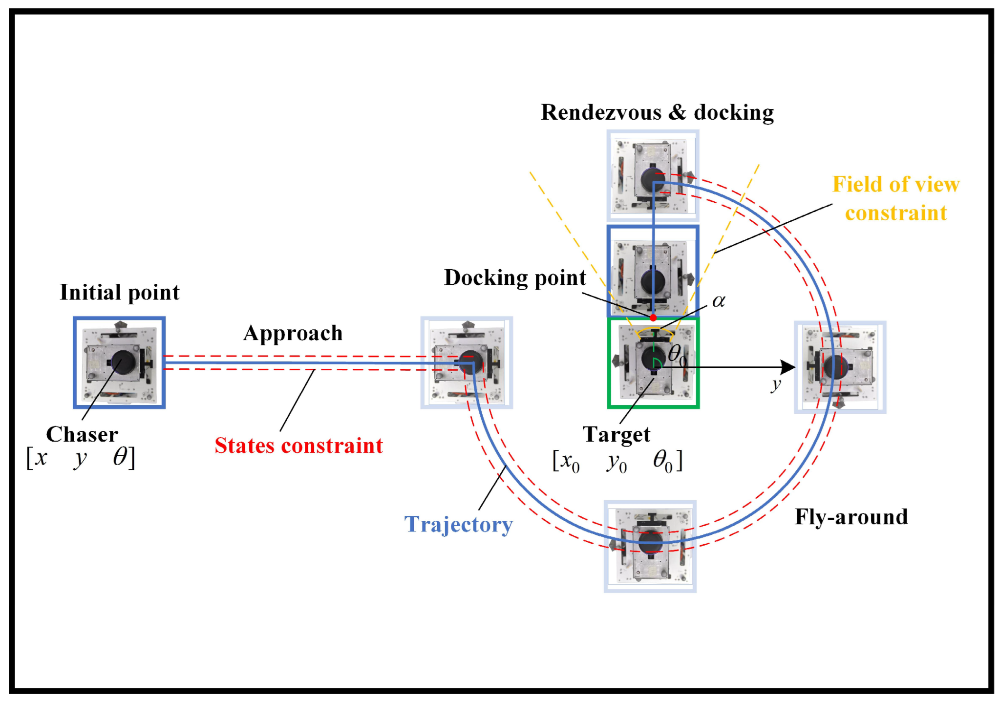
  • Furthermore, this paper introduces a novel sampling-based model predictive control method, which has been developed for the purpose of the ground simulation of rendezvous and docking. Docking is a real-time, optimal, and constraint-handling capability that is capable of handling multiple constraints.
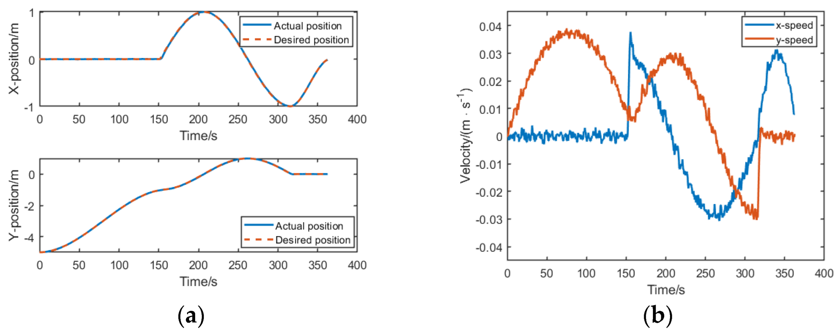
  • The CAPF-NMPC method is validated by an air float satellite simulator in a real environment, which proves its high control accuracy and low consumption of computational resources.
The remainder of this paper is structured as follows: Section 2 presents the design and implementation of the simulation platform, including its detailed parameters; Section 3 introduces the design of the rendezvous-docking controller and the theoretical basis of the CAPF-NMPC method in detail; Section 4 validates the efficacy of the proposed method, which is evaluated through simulation experiments, and the method is compared and analyzed with other methods; and Section 5 demonstrates the results of the actual experiments and proves the method’s real-time performance. Finally, Section 6 summarizes the research results of this paper, discusses the limitations of the research, and proposes improvement measures.

2. The Air Float Satellite Simulator

2.1. Overall Structure Design

The overall structural design of the air float simulator is based on a modular concept, as shown in Figure 1.
The simulator consists of two main parts: the satellite and the air-floated micro thruster system, where the air-floated micro thruster module is located at the bottom with the thrusters, which suspend the simulator on the marble surface and provide translational and rotational motion. The simulated satellite is located at the top and includes components, such as batteries, power control, attitude control, visual image processing, a communication board, and cameras. These components are responsible for the power supply, navigation, guidance, and control of the simulator. The two modules are connected through electrical interfaces.
The configuration of the thrusters is of greater consequence for the development of the control algorithm; therefore, the following is a comprehensive account of the composition of the air float micro thrust system. As illustrated in Figure 2, the system comprises a micro thrust control board, battery, high-pressure gas tank, pressure-reducing valve, gas-filling valve, planar air float bearing, and pipelines. Eight cold gas thrusters are arranged in a symmetrical configuration around the simulator, with two thrusters positioned on either side. Each thruster is capable of generating a thrust force of 100   mN and is able to perform three degrees of freedom in the x, y translation and z rotation.
The micro-thrust control board incorporates a thrust distribution algorithm for apportioning the thrust resolved by the upper controller to the eight thrusters, thereby propelling the simulator in motion; the thrust distribution method is described in Section 3.3. The coordinate system, as shown in Figure 3, includes the body coordinate system x b o y b and inertial coordinate system x o y .
Accordingly, the rotation matrix R b c of the air float satellite simulator body coordinate system rotated to the inertial coordinate system, can be obtained as follows:
R b c = cos θ sin θ 0 sin θ cos θ 0 0 0 1
Furthermore, certain components of the air float simulator require additional attention; for example, the satellite battery employs 15 sections of 2.6 Ah capacity 18650 monomer 5 series and 3 parallel compositions, ensuring that the solenoid valves of the air-floated micro thruster system are operational. Table 1 presents the remaining parameters of the air float simulator.

2.2. GNC Software Architecture Design

The software of the air float satellite simulator system is divided into two parts: the onboard guidance, navigation, and control (GNC) software and the ground measurement and control software, which are operated on the simulated satellite and the ground station computers, respectively. The GNC software is primarily used for satellite simulator mission control, generating control commands, and conducting autonomous maneuvers. The ground measurement and control software are mainly used for the uplink of navigation information, the downlink display, and the storage of satellite information. Real-time communication between the satellite and the ground measurement software is facilitated through WIFI; however, due to the use of a column antenna for satellite simulator communication, the electromagnetic wave density in the transverse direction is subject to faster attenuation [34]. This results in an effective communication distance of 10 m for the satellite, which may be insufficient if the satellite moves farther away, potentially leading to communication interruptions.
The structure of the GNC software is shown in Figure 4; the navigation data are processed by the visual image processing module, which can receive absolute navigation data sent by the ground measurement and control station or relative navigation from the visual information of the camera and generates the navigation information for the positional attitude and velocity of the simulator. The guidance and control are deployed in the microprocessor, where the guidance module is employed to receive command data, including mission commands and target information, and to generate a reference trajectory. The control module is utilized to track the reference trajectory. The controller was constructed with the objective of monitoring the reference trajectory and subsequently generating the acceleration and angular acceleration values within the inertial system; subsequently, the signal is transformed into eight nozzle thrusts on the micro-thrust control board.
Where x , y , and θ denote the position and attitude under the inertial system, x ˙ , y ˙ , and θ ˙ denote the velocity and angular velocity, x r ,   y r ,   θ r is the reference trajectory, u x ,   u y ,   u τ represents the controller output, including the acceleration and angular acceleration of the simulator in the inertial coordinate, and f 1 ,   f 2 ,   ,   f 8 represents the thrust generated by eight nozzles.

2.3. Dynamical Model

The relative motion of the spacecraft in close proximity in space is represented by the Hill–Clohessy–Wiltshire (HCW) equations. For the close-range space operation between satellites, when neglecting nonlinear orbit perturbations, motion can be approximated in linear equations. The following is the establishment of the motion model for the simulator:
x ¨ = F x m c = u x y ¨ = F y m c = u y θ ¨ = F τ I z = u τ
where x ¨ , y ¨ , and θ ¨ are the acceleration and angular acceleration of the chaser air float simulator in the inertial frame, respectively; F x and F y represent the thrust in the direction of inertial systems x and y , respectively; and F τ is the torque. m c and I z are tracking the mass and moment of inertia of the simulator, respectively.

3. Controller Design

The control objective of this study is to drive the chaser simulator along a predefined trajectory to approach the target and complete the docking maneuver. The chaser simulator maneuvers around the target along predefined waypoints while maintaining attitude alignment. This section applies CAPF-NMPC and introduces the concept of rolling horizon optimal estimation to design an optimal tracking controller. This section presents the establishment of the optimal control model for rendezvous and docking, followed by an introduction to the CAPF-NMPC solution method.

3.1. Optimal Control Modeling

In practical engineering problems, both measurement and control are implemented in a discrete version as follows:
X k + 1 = f ( X k ,   u k )
At time k , there is the corresponding state vector X k = x y θ x ˙ y ˙ θ ˙ T and the control vector u k = u x u y u τ T ; the kinetic equation f ( ) is established in Section 2.3; and the recursive initial value X 0 is defined in terms of the initial state of the air float simulator.

3.1.1. Objective Function

In the context of the tracking optimal control problem, the objective is to enable the controlled object to determine the optimal control input for a given trajectory. This ensures that the system follows the specified trajectory while optimizing performance according to other relevant indicators.
Assuming that the control objective is, for Y k , to trace the reference input Y R = x r y r θ r T , and Y k is the measurement value of the state vector, the constrained MPC optimization problem can be formulated as follows:
min u k : k + H k k + H Y k Y R Q 2 + u k R 2 s . t . X t + 1 = f X t ,   u t     g j X t ,   u t 0 j = 1 ,   ,   m     t = k ,   ,   k + H p
where H p is the prediction time domain of NMPC, u k : k + H = u k , u k + 1 , , u k + H is the control input sequence, Q and R are the weighting matrix, and X k is known. The above problem seeks to determine the optimal control input sequence u k : k + H to minimize the objective function, which is the weighted quadratic sum of the control cost and tracking error of the next H p steps under the premise of dynamic and state quantity constraints. The literature usually adopts the numerical optimization method to calculate u k : k + H . Once the optimization is complete, the first element of u k : k + H , u k , is applied to control the system, and this optimization and control are repeated periodically, which is called the rolling optimization process.

3.1.2. Attitude Alignment Constraint

During the execution of the rendezvous and docking operation, it is essential not only to precisely control the chaser simulator to reach the docking point but also ensure correct attitude alignment throughout the approach and fly-around processes. Additionally, it is crucial to maintain the angular velocity within a specified range. Accordingly, the following constraints are imposed on the state variables:
θ min θ θ max
where θ min θ max denotes the maximum range of allowable attitude deviation, and the stability of its pointing is ensured by limiting the attitude deviation through the application of soft constraints.

3.1.3. Velocity Constraint

To ensure the safety of motion, the chaser simulator should maintain its velocity below a certain threshold throughout the gradual approach to the target simulator. Additionally, when in close proximity to the target simulator, the final docking should be achieved only through a gentle impact with the docking mechanism. Therefore, the following constraint is imposed on the velocity of the simulator:
v x v x max v y v y max
where v x max v y max denotes the upper and lower bounds of the speed.

3.1.4. Field of View Constraint

At the outset of the docking process, when the chaser enters the range of the vision sensor, the target vision sensor is activated and guides the chaser to correct the positional offset. It is imperative to ensure that the chaser remains within the field of view of the target sensor, thereby enabling the sensor to measure the motion information of the tracking simulator in real-time. As illustrated in Figure 5, the region delineated by the yellow line represents the field of view of the target vision camera.
tan θ 0 α 2 y y 0 x x 0 tan θ 0 + α 2
where the field of view angle is α , the attitude of the target simulator is θ 0 , and x 0 ,   y 0 represents the coordinates of the target.

3.1.5. Thrust Saturation Constraint

The thruster magnitude of the simulator is constrained by the actuator mechanism. When solving for control force, engineering constraints must be added to limit their input range, ensuring that the output thrust does not exceed the maximum thrust actually executed. Specifically, the control variable saturation constraints can be expressed as follows:
u k u max
where u max = u x max u y max u τ max T indicates the maximum value of acceleration and angular acceleration.

3.2. Optimization Controller by CAPF-NMPC

In actual engineering tasks, although optimal control can handle complex constraints, it consumes considerable computational resources and involves large computational efforts. Moreover, due to limitations in the power consumption of micro/nano satellite chips or cost considerations, the performance of microprocessors is generally not very high. Therefore, ensuring the real-time computation of optimal control is crucial for air float simulators.
To address the limited computing resources of micro/nano satellite systems, a solution utilizing CAPF-NMPC to handle multiple constraints and effectively reduce computational efforts is proposed for the optimal control of air float simulators [35].
In order to realize the measurement process of the particle filter, Equation (2) is rewritten to establish a virtual measurement system. Time k is recorded, where Z k = X k T u k T T is the state quantity, Y k = H X k + V k is the measurement value, and H is the measurement matrix. In the time domain of t = k ,   ,   k + H p , the system equation is in the following form:
Z t + 1 = f Z t + W t Y t = H X t + V t
where the control quantities are generated by random signals and W t , V t are additive perturbations. From the above equation, the combination state Z t of the current time domain, including the optimal trajectory and optimal control variables, can be estimated using the Moving Horizon Estimation (MHE). By extracting the control variables, optimal control can be achieved by applying them to the simulator.

3.3. Thrust Distribution Method

Based on the NMPC optimization problem established in Section 3.1 and the solution method in Section 3.2, we can obtain the current optimal control vector u ^ k at each moment, representing the acceleration and angular acceleration in the inertial system, and therefore, convert it to the thrust in the desired body coordinate system.
F b = B R c b u ^ k
where F b = F x b F y b F τ T denotes the magnitude of the thrust in the body system, R c b denotes the rotation matrix from the inertial system to body system, and B denotes the parameter matrix of mass and moment of inertia.
B = m 0 0 0 m 0 0 0 I z
As shown in Figure 3, by denoting the thrust of the eight thrusters as f = f 1 f 2 f i T ,   i = 1 ,   ,   8 , the forces and moments exerted on the simulator under the prevailing conditions can be expressed as follows:
F b = Γ f
where Γ denotes the transformation matrix that maps the force in a given direction to the corresponding thruster in accordance with the specified thruster layout.
Γ = 1 1 0 0 1 1 0 0 0 0 1 1 0 0 1 1 l l l l l l l l
Here, l represents the force arm of the thruster. Consequently, if the forces and moments exerted by the system are identified, the thrust output on each thruster can be calculated as follows:
f = Γ + F b
Remark 1. 
Γ + represents the additive inverse, also known as the Moore–Penrose inverse. Given that the matrix  Γ  is a row-full rank matrix of dimension 3 × 8, it follows that the generalized inverse matrix can be solved from  Γ + = Γ m = Γ H Γ Γ H 1 .
Normally, the force output from the thruster is constrained to be non-negative and cannot exceed the maximum capacity of the thruster. Consequently, the aforementioned equation is rewritten as follows: f = 2 Γ + u ; when f i 0 , let f i = 0 ; and when f i 100 , let f i = 100 .
Furthermore, the desired thrust magnitude is mapped to time duration by the pulse-width modulation (PWM), whereby the desired thrust magnitude is fitted by continuous thrust over a period of time. This is based on the assumption that the control period and the time of each thruster jet are represented by the variable.
t i = T s f i f max

4. Simulation Verification

Simulations are conducted on a 12th Gen Intel (R) Core (TM) i9-12900H platform using MATLAB 2021b. In the simulation scenario, the target air float simulator is positioned at the origin of the coordinate system, while the chaser simulator is initially located in [0, −5] m. This scenario includes the following three typical close-range spatial operation modes: “Straight Line Approach”, “Fly Around”, and “Rendezvous and Docking.” In the straight approach line, the chaser simulator accelerates to within 1 m of the target, then flies around the target at a 1 m radius, maintaining a constant orientation towards the target. Table 2 outlines the characteristic parameters of the simulator and the simulation settings for this scenario.
Considering the problem of computing resource consumption, the selection of the prediction horizon and number of particles should be as small as possible under the premise of ensuring control accuracy. Monte Carlo simulations with varying values indicate that the system exhibits enhanced performance and reduced computational latency when the prediction time domain is set to eight and the number of particles is 100.
The simulation results are depicted in the following figures, illustrating the trajectory of planar motion, the distance between the simulators, and thrust acceleration values. Figure 6a presents the variation in the relative position of the chaser simulator during the approach and flight-around tasks. Figure 6b shows the relative velocity variation in the simulators during control. Figure 7 provides position error curves for the two methods, while Figure 8 illustrates the attitude error curves. Finally, Figure 9 displays the variation in force exerted by the micro thrusters on the simulator body.
As illustrated in Figure 7 and Figure 8, the CAPF-NMPC method demonstrates superior performance in suppressing perturbation relative to the traditional rendezvous and docking approach, thereby ensuring high accuracy throughout the docking process. The presented results substantiate this observation. Figure 6b illustrates that the chaser’s velocity in the final stage of docking is only 0.008 m/s, indicating that the docking was produced by a weak collision. This provides further evidence of the effectiveness of the controller.
Based on the above simulation results, the following conclusions can be drawn: the simulator accurately performs close-range approach tasks, conducts reconnaissance circling the target at predetermined waypoints, and successfully docks with the target’s docking surface. Throughout its motion, the chaser simulator consistently maintains its orientation towards the target simulator. Figure 6a demonstrates that the chaser simulator reaches the desired positions in all displacement directions, confirming successful docking. Additionally, the velocity and thrust saturation constraints are satisfied, as shown by the data. The error change curves indicate a position control error of less than 0.03 m and an attitude control precision of less than 3°. These findings collectively validate the effectiveness and precision of the model predictive control algorithm in guiding the air float simulator during trajectory tracking.

5. Experimental Verification

The experiment is conducted using a three-degrees-of-freedom air float simulator, as illustrated in Figure 10a, on a 15   m × 15   m marble horizontal platform and is localized using the absolute navigation system shown in Figure 10b. The simulator’s controller, deployed on an STM32H743 spacecraft computer with a 480 MHz Arm Cortex-M7 core, was programmed in C and executed on the STM32H743. The experimental setting is close to the simulation. One difference to this is that the initial attitude is 90°.
From the experimental results shown in Figure 11 and Figure 12, it is evident that the physical verification aligns closely with the simulation results. However, in terms of attitude control, there is some degree of oscillation due to the influence of disturbance torques during the actual control process. This is constrained by the computational capabilities of the experimental simulator and environmental factors. Nevertheless, as depicted in Figure 11a and Figure 12, the representation of chaser is indicated by blue platforms, with the trajectory by a blue line. The transparency of the platforms is highest at the initial point and decreases as they dock. It can be observed that the trajectory control process appears to be relatively smooth, indicating the superior predictive and constraint handling capabilities of CAPF-NMPC.
Compared with existing rendezvous and docking solutions, this study demonstrates several advantages. The proposed optimal control scheme is specifically designed for operation on low-computational-power microprocessors, enhancing the generalizability of optimal control compared to systems that rely on high-performance minicomputers, as mentioned in ref. [31]. Unlike the simplified linear models used in previous studies, the CAPF-NMPC method employed in this paper could account for model nonlinearity and incorporate nonlinear constraints, leading to more precise rendezvous and docking. Furthermore, compared to the intelligent docking system described in ref. [36], the intelligent three-degrees-of-freedom air float simulator developed in this study is equipped with a richer array of sensors, including an absolute navigation system, vision cameras, and LIDAR. This simulator not only verifies docking maneuvers but also supports a wide range of other space maneuvering tasks, such as formation flying, robotic arm grasping, and orbital gaming, thereby broadening its applicability.
The research in this paper also has the following limitations: 1. the CAPF-NMPC method increases the ability to deal with uncertainty to a certain extent, but it may still show a lack of robustness in the face of strong nonlinearities, a wide range of perturbations, and system failures; 2. it should be noted that the capacity of the WIFI communication antenna is limited, which may result in the navigation communication link being disconnected if the satellite moves to a position that is distant from the ground station.

6. Conclusions

This study investigates a three-degrees-of-freedom air float satellite simulator with micro thrusters aimed at ground-based experiments for a close-range approach and flight around the control of microsatellites. The simulator’s guidance and control system use a particle filter model predictive control algorithm, which reduces the computational complexity of optimal control in a single step, enabling precise control on low-power spacecraft computers. Then, multiple constraints are designed for close-range rendezvous and docking. Simulation validates the effectiveness of the simulator’s rendezvous and docking control methods. The results demonstrate that the algorithm achieves stable and precise motion control. The experiments also show the system’s capability to effectively simulate the motion of microsatellites, affirming the feasibility and efficacy of the proposed control method, the docking accuracy of approximately 0.03 m, attitude accuracy of approximately 3°, and velocity of no more than 0.05 m/s in comparison to the PID controller; the results demonstrate that the proposed controller exhibits superior accuracy.
The work in this paper will be further investigated in the future: due to the sampling nature of particle filtering, parallel computing methods can be used to process multiple samples simultaneously and further increase the computational speed; the dimensionality of the model will be extended from a planar three-degrees-of-freedom model to a real six-degrees-of-freedom spatial environment, taking into account the effects of intrusion; the target may also be considered non-cooperative and may tumble, rotate, etc., which is very common in real space. Furthermore, efforts may be directed toward enhancing the navigational capabilities of the air float satellite simulator. This may be achieved by optimizing the efficiency and reliability of data transmission and by minimizing the probability of disruption to the navigation link through the implementation of a GNSS data compression method, as previously documented in the literature [37].

Author Contributions

Conceptualization, D.C.; methodology, L.X.; software, L.X.; validation, D.C., L.X. and C.W.; formal analysis, L.X.; investigation, L.X.; resources, D.C.; data curation, L.X.; writing—original draft preparation, D.C.; writing—review and editing, D.C.; visualization, L.X.; supervision, D.C.; project administration, W.L.; funding acquisition, W.L. All authors have read and agreed to the published version of the manuscript.

Funding

This research was funded by the key laboratory of space intelligent control technology stability, grant number HTKJ2023KL502009.

Data Availability Statement

Data are contained within the article.

Conflicts of Interest

The authors declare no conflicts of interest.

References

  1. Do, P.X.; Nakasuka, S. LEO-to-GEO laser communication-An enhancement of the communication capability of micro/nano-satellites. AIP Conf. Proc. 2021, 2366, 010001. [Google Scholar]
  2. Sansone, F.; Francesconi, A.; Corvaja, R.; Vallone, G.; Antonello, R.; Branz, F.; Villoresi, P. LaserCube optical communication terminal for nano and micro satellites. Acta Astronaut. 2020, 173, 310–319. [Google Scholar] [CrossRef]
  3. Radhakrishnan, R.; Edmonson, W.W.; Afghah, F.; Rodriguez-Osorio, R.M.; Pinto, F.; Burleigh, S.C. Survey of Inter-Satellite Communication for Small Satellite Systems: Physical Layer to Network Layer View. IEEE Commun. Surv. Tutorials 2016, 18, 2442–2473. [Google Scholar] [CrossRef]
  4. Xue, Y.; Li, Y.; Guang, J.; Zhang, X.; Guo, J. Small satellite remote sensing and applications–history, current and future. Int. J. Remote Sens. 2008, 29, 4339–4372. [Google Scholar] [CrossRef]
  5. Yao, Y.; Zhou, Y.; Yuan, C.; Li, Y.; Zhang, H. On-board intelligent processing for remote sensing images based on 20 kg micro-nano satellite. In Proceedings of the 2021 IEEE International Geoscience and Remote Sensing Symposium IGARSS, Brussels, Belgium, 11–16 July 2021. [Google Scholar]
  6. Liu, H.; Liu, C.; Liu, S.; Yong, Q.; Wang, X.; Zhao, Y.; Ding, Y.; Xie, P. Design of a focusing system for micro-nano satellite remote sensing camera based on thermal control technology. J. Therm. Stress. 2024, 47, 909–926. [Google Scholar] [CrossRef]
  7. Liu, Y.; Tian, L.; Liu, G.; Li, Z.; Dai, Y.; Dong, Z. Regional Navigation Reconstruction Strategy and Performance Simulation Based on Micro-nano Satellites. In Proceedings of the 2021 IEEE International Instrumentation and Measurement Technology Conference (I2MTC), Glasgow, UK, 17–20 May 2021. [Google Scholar]
  8. You, Z. Space Microsystems and Micro/nano Satellites; Butterworth-Heinemann: Oxford, UK, 2017. [Google Scholar]
  9. David, R.V. Design of a Thruster-Assisted Control for 1U CubeSat Orbit Maintenance and Drag Mitigation with NASA 42. Bachelor’s Thesis, Universitat Politècnica de Catalunya, Barcelona, Spain, 2023. [Google Scholar]
  10. Xu, S.; Liao, W. Large angle attitude control of cubesat based on multi-objective optimization. J. Phys. Conf. Ser. 2024, 2820, 012050. [Google Scholar] [CrossRef]
  11. Yuan, B.; Yang, D.; Meng, Z. Research on Sun-Oriented Spin-Stabilized Attitude Control of Micro/Nano Satellite Using Only Magnetic Control. Electronics 2023, 12, 362. [Google Scholar] [CrossRef]
  12. Xu, S.; Lu, Z.; Zhang, X.; Liao, W. Attitude stability control of micro-nano satellite orbit maneuver based on bias momentum. J. Phys. Conf. Ser. 2021, 2083, 022060. [Google Scholar] [CrossRef]
  13. Domenico, P. Mission Analysis for CubeSat Rendezvous and Docking Operations. Master’s Thesis, Politecnico di Torino, Turin, Italy, 2023. [Google Scholar]
  14. Hu, Y.; Han, D.; Lu, Z.; Liao, W. Constraint tightening-based control for small-satellite formations using differential aerodynamic forces. Adv. Space Res. 2024, 74, 872–889. [Google Scholar] [CrossRef]
  15. Jeon, S.; Park, S.-Y.; Kim, G.-N. Relative Orbit Control Algorithms and Scenarios for the Inertial Alignment Hold Demonstration Mission by CubeSat Formation Flying. Aerospace 2024, 11, 135. [Google Scholar] [CrossRef]
  16. Wang, C.; Chen, D.; Liao, W. Research on maneuver strategy in satellite observation and counter-observation game. Adv. Space Res. 2024, 74, 3170–3185. [Google Scholar] [CrossRef]
  17. Chekakta, Z.; Aouf, N. CaDNET: An End-to-End Plenoptic Camera-Based Deep Learning Pose Estimation Approach for Space Orbital Rendezvous. IEEE Sens. J. 2024. [Google Scholar] [CrossRef]
  18. Sandnas, M.; Spencer, D.B. RVS® 3000-3D LIDAR–3D imaging and pose estimation during first geo satellite servicing. In Proceedings of the 44th Annual American Astronautical Society Guidance, Navigation, and Control Conference, 2022; Springer International Publishing: Cham, Switzerland, 2022. [Google Scholar]
  19. Zeng, N.; Xu, G.; Chen, D.; Liu, X.; Lu, Z. A time-fuel hybrid optimal guidance for micro/nano satellite’s glideslope approach. J. Phys. Conf. Ser. 2024, 2764, 012046. [Google Scholar] [CrossRef]
  20. Zhu, X.; Chen, J.; Zhu, Z.H. Adaptive sliding mode disturbance observer-based control for rendezvous with non-cooperative spacecraft. Acta Astronaut. 2021, 183, 59–74. [Google Scholar] [CrossRef]
  21. Wang, C.; Chen, D.; Liao, W.; Liang, Z. Autonomous obstacle avoidance strategies in the mission of large space debris removal using potential function. Adv. Space Res. 2023, 72, 2860–2873. [Google Scholar] [CrossRef]
  22. Xu, Z.; Chen, Y.; Xu, Z. Optimal guidance and collision avoidance for docking with the rotating target spacecraft. Adv. Space Res. 2019, 63, 3223–3234. [Google Scholar] [CrossRef]
  23. Stesina, F. Tracking Model Predictive Control for Docking Maneuvers of a CubeSat with a Big Spacecraft. Aerospace 2021, 8, 197. [Google Scholar] [CrossRef]
  24. Eren, U.; Prach, A.; Koçer, B.B.; Raković, S.V.; Kayacan, E.; Açıkmeşe, B. Model Predictive Control in Aerospace Systems: Current State and Opportunities. J. Guid. Control Dyn. 2017, 40, 1541–1566. [Google Scholar] [CrossRef]
  25. Federico, G. Ensuring Safe Docking Maneuvers on Floating Platform Using Nonlinear Model Predictive Control (NMPC); Luleå University of Technology, Department of Computer Science, Electrical and Space Engineering: Luleå, Sweden, 2024. [Google Scholar]
  26. Dong, K.; Luo, J.; Dang, Z.; Wei, L. Tube-based robust output feedback model predictive control for autonomous rendezvous and docking with a tumbling target. Adv. Space Res. 2019, 65, 1158–1181. [Google Scholar] [CrossRef]
  27. Dong, K.; Luo, J.; Limon, D. A novel stable and safe model predictive control framework for autonomous rendezvous and docking with a tumbling target. Acta Astronaut. 2022, 200, 176–187. [Google Scholar] [CrossRef]
  28. Oumer, A.M.; Kim, D.-K. Real-Time Fuel Optimization and Guidance for Spacecraft Rendezvous and Docking. Aerospace 2022, 9, 276. [Google Scholar] [CrossRef]
  29. Bashnick, C.; Ulrich, S. Fast Model Predictive Control for Spacecraft Rendezvous and Docking with Obstacle Avoidance. J. Guid. Control Dyn. 2023, 46, 998–1007. [Google Scholar] [CrossRef]
  30. Behrendt, G.; Soderlund, A.; Hale, M.; Phillips, S. Autonomous Satellite Rendezvous and Proximity Operations with Time-Constrained Sub-Optimal Model Predictive Control. IFAC-PapersOnLine 2023, 56, 9380–9385. [Google Scholar] [CrossRef]
  31. Fear, A.; Lightsey, E.G. Autonomous Rendezvous and Docking Implementation for Small Satellites Using Model Predictive Control. J. Guid. Control Dyn. 2024, 47, 539–547. [Google Scholar] [CrossRef]
  32. Ravikumar, L.; Padhi, R.; Philip, N. Trajectory optimization for Rendezvous and Docking using Nonlinear Model Predictive Control. IFAC-PapersOnLine 2020, 53, 518–523. [Google Scholar] [CrossRef]
  33. Park, H.; Zappulla, R.; Zagaris, C.; Virgili-Llop, J.; Romano, M. Nonlinear model predictive control for spacecraft rendezvous and docking with a rotating target. In Proceedings of the 27th AAS/AIAA Spaceflight Mechanics Meeting, San Antonio, TX, USA, 5–9 February 2017. [Google Scholar]
  34. Buckus, R.; Chlebnikovas, A.; Strukcinskiene, B.; Stukas, R.; Austys, D.; Caban, J.; Bogucki, M.; Bogucki, M.; Seleviciene, V.; Kilikevičius, A.; et al. Simulating the dispersion of the energy flux density of the electromagnetic field generated by antennas for mobile communications. Electronics 2022, 11, 2431. [Google Scholar] [CrossRef]
  35. Iman, A.; Zeng, S.; Fang, H. Nonlinear model predictive control based on constraint-aware particle filtering/smoothing. In Proceedings of the 2021 American Control Conference (ACC), New Orleans, LA, USA, 25–28 May 2021. [Google Scholar]
  36. Lion, L.; Caon, A.; Olivieri, L.; Branz, F.; Francesconi, A. Kinematic tests on a docking mechanism for microsatellites. CEAS Space J. 2023, 16, 445–455. [Google Scholar] [CrossRef]
  37. Amnon, R.; Wiseman, Y. Compression of GNSS data with the aim of speeding up communication to autonomous vehicles. Remote Sens. 2023, 15, 2165. [Google Scholar] [CrossRef]
Figure 1. Overall structure of air float satellite simulator.
Electronics 13 03571 g001
Figure 2. Air float micro thruster system.
Electronics 13 03571 g002
Figure 3. Coordinate system and thrust.
Electronics 13 03571 g003
Figure 4. System onboard GNC software.
Electronics 13 03571 g004
Figure 5. Simulator rendezvous, docking process, and constraint schematics.
Electronics 13 03571 g005
Figure 6. Change in chaser state vector under CAPF-NMPC method: (a) relative position change curve; (b) velocity change curve.
Electronics 13 03571 g006
Figure 7. Position error versus time curve: (a) position error with PID; (b) position error with CAPF-NMPC.
Electronics 13 03571 g007
Figure 8. Attitude error versus time curve: (a) attitude error with PID; (b) attitude error with CAPF-NMPC.
Electronics 13 03571 g008
Figure 9. Thrust with CAPF-NMPC method.
Electronics 13 03571 g009
Figure 10. Air float satellite simulation system: (a) air float satellite simulator; (b) absolute navigation system and high-precision horizontal marble platforms.
Electronics 13 03571 g010
Figure 11. Changes in state vector in the chaser rendezvous and docking experiment: (a) relative position change curve; (b) attitude change curve; (c) velocity change curve; and (d) angular velocity change curve.
Electronics 13 03571 g011
Figure 12. Rendezvous and docking trajectory.
Electronics 13 03571 g012
Table 1. Parameters of air float simulator.
Parameter TypeNameValueUnit
Structure parameterQuality11.2kg
Moment of inertia0.1106kg·m2
Dimension of envelope0.3 × 0.3 × 0.5m
Thruster parametersMagnitude of thrust0.1N
Thruster moment arm0.1m
Battery parameterNominal voltage24V
Battery capacity7.5Ah
Table 2. Simulation parameters of air float simulator.
ParametersValueUnit
Time step t s 0.5s
Prediction horizon H p 8dimensionless
Number of particles N s 100dimensionless
Attitude pointing constraint θ min ,   max [−5, 5]degree
Speed limits V x max ,   y max [−0.05, 0.05]m/s
Field of view angle α 30degree
Thrust upper and lower limits u x ,   y ,   τ max [0, 0.015]m/s2
Docking interface of the simulator [−0.3, 0]m
Disturbance torque f d 10 N m
Disclaimer/Publisher’s Note: The statements, opinions and data contained in all publications are solely those of the individual author(s) and contributor(s) and not of MDPI and/or the editor(s). MDPI and/or the editor(s) disclaim responsibility for any injury to people or property resulting from any ideas, methods, instructions or products referred to in the content.

