Article

Low-Voltage Water Pump System Based on Permanent Magnet Synchronous Motor

1
School of Information and Electronic Engineering, Zhejiang University of Science and Technology, Hangzhou 310023, China
2
College of Optical and Electronic Information, China Jiliang University, Hangzhou 310018, China
3
College of Media Engineering, Communication University of Zhejiang, Hangzhou 310018, China
*
Author to whom correspondence should be addressed.
Electronics 2024, 13(18), 3674; https://doi.org/10.3390/electronics13183674
Submission received: 29 July 2024 / Revised: 31 August 2024 / Accepted: 13 September 2024 / Published: 16 September 2024

Abstract

:
This paper designs a safe, low-cost, and efficient permanent magnet synchronous motor (PMSM) booster pump system. The aim is to enhance the pump’s safety and reduce the incidence of electric shock accidents, while also achieving cost reduction and efficiency improvement. The pump components are made of a plastic material, and a safe voltage of 36 V is used as the operating voltage. Additionally, the PMSM is chosen to replace the induction motor (IM) as the pump’s driving device, utilizing sensorless control and field-weakening control strategies. The study results show that when the flow rate is 1.51 m3/h, the efficiency of the PMSM low-voltage pump can reach up to 20.86%. At the same flow rate of 1 m3/h, compared to other pumps, the PMSM low-voltage pump exhibits higher head, energy savings, and efficiency. The proposed PMSM low-voltage pump offers advantages such as high efficiency, energy savings, safety, and low cost. This study provides a reference for the domestic PMSM pump industry.

1. Introduction

Water pumps are versatile mechanical devices with wide usage and broad applications, widely used in agricultural irrigation, urban water supply, petrochemical industries, and more. With the rapid development of China’s socio-economic landscape, the progress of urbanization, population growth, and the increase in residential building heights, issues such as unstable water pressure in municipal water supplies have become increasingly prominent. Consequently, the demand for pumps has been growing. To meet daily water needs, more and more residents are installing booster pumps at their household water inlets. However, the use of pumps also brings about energy consumption issues, with around 20% of the total electricity consumed nationwide used for operating various pump units. Additionally, the operational efficiency is relatively low. Therefore, exploring strategies to improve energy efficiency to address potential future energy shortages is of great importance for the sustainable development of the international community [1].
Currently, many scholars and manufacturers have developed various types of motor-driven pumps. For example, Kashif et al. [2]. proposed a Modified Active-Power Model Reference Adaptive System (MAP-MRAS) for PMSM solar water pumps (SWP), which improved the reliability of SWP by removing current sensors and speed sensors. This pump motor has a rated voltage of 220 V. Taizhou Hanbei Pump Industry Co., Ltd. (Wenling, China) has launched two models of cast iron water pumps: a vortex self-priming pump and a centrifugal pump. The self-priming pump is driven by a single-phase AC induction motor with a rated voltage of 220 V, while the centrifugal pump is driven by a squirrel-cage AC induction motor, also with a rated voltage of 220 V. SHIMGE Pump Industry Group Co., Ltd. (Wenling, China) has introduced a stainless-steel submersible pump, which is driven by a single-phase AC motor with a rated voltage of 220 V.
To achieve motor control, several control algorithms are employed, including sensorless control and weak field control. In the zero-low speed domain, Kim et al. [3] proposed a sensorless control method based on rotating high-frequency voltage signal injection. This method uses the voltage difference and current difference equations to extract rotor position information and improves the accuracy of rotor position information through an all-pass filter. Shen et al. [4] proposed an improved I-F control method that adjusts the amplitude of the current vector using a PI regulator, while simultaneously measuring the instantaneous active power of the motor to adjust the speed of the current vector. This approach increases the system’s damping torque and accelerates the speed convergence process. In the medium-speed and high-speed domain, Bolognani et al. [5] proposed a new method for adjusting the covariance matrix in an EKF-based PMSM driver. By normalizing the covariance matrix, this method overcomes the drawbacks of trial and error adjustments. Lu et al. [6] proposed a new high-speed SMO that eliminates sliding-mode chatter and improves responsiveness by using the Sigmoid function as the switching function in the control law. In the case of weak magnetic field expansion, Lai et al. [7] proposed a method based on the gradient descent algorithm with a discrete search space and appropriate constraints to optimize the efficiency of PMSM-driven systems, ensuring fast search speed and reducing the impact of measurement uncertainty. Bai et al. [8] proposed a leading angle field-weakening control method, which establishes a voltage loop to maintain the stability of the field-weakening system through the utilization of the motor terminal voltage and the DC bus voltage. In different speed regions, optimal d-axis and q-axis current commands can be calculated based on the lead angle of the permanent magnet synchronous motor.
However, most pumps use metal materials and high-voltage driving methods, which pose potential safety risks. In the event of an electrical fault or operational error, contact with high-voltage electricity could lead to electric shock accidents, posing a threat to personal safety. To address these issues, this paper proposes a solution that uses plastic as the structural material for the pump and converts high-voltage electricity to low-voltage electricity to power the pump. It also proposes using a permanent magnet synchronous motor (PMSM) instead of an induction motor (IM) as the pump drive motor and employs sensorless control and field-weakening control strategies to enhance the pump’s performance. The remainder of this paper is organized as follows: Section 2 optimizes the pump system and introduces the working principle of the pump. Section 3 introduces the sensorless control algorithm and field-weakening control algorithm. Section 4 establishes a test platform to validate the proposed pump system. Finally, Section 5 concludes the paper.

2. System Design

2.1. Structure of the Pump

To reduce leakage and electric shock accidents, all the structural components of the pump are made from plastic materials. Plastic is an excellent electrical insulator with advantages such as corrosion resistance and ease of processing. Compared to metal materials, plastic is cheaper and lighter, which effectively reduces the overall weight of the pump, improves its portability, and eliminates water quality issues caused by rust.
The dimensions of the pump are 292 mm in length, 205 mm in width, and 200 mm in height, with a capacity of 2.5 L and a diameter of 25 mm. The exploded view of its structure is shown in Figure 1, which mainly consists of the upper cover, dust cover, middle cover, base, display board, flow pressure sensor, pump body, PMSM, motor drive board, and switching power supply. Before using the pump, ensure the pump body is filled with liquid. The working principle of the pressure booster pump is to use the motor to drive the impeller to rotate at high speed, causing the liquid in the impeller to also rotate. Under the action of centrifugal force, the liquid is expelled from the impeller, creating a vacuum low-voltage zone at the center of the impeller. The liquid enters the pump body due to atmospheric pressure. The expelled liquid enters the pump body’s diffusion chamber, which plays a role in regulating and stabilizing the flow of the liquid throughout the process. Inside the diffusion chamber, the liquid’s speed gradually decreases while its kinetic and pressure energies increase. Finally, the liquid is expelled through the outlet.

2.2. Selection of the Motor

Traditionally, IMs have been the motor of choice for residential and industrial pump applications [9]. This is mainly due to the ruggedness, low cost, and low maintenance requirements of IMs [10]. However, IMs face issues such as low torque density, low power factor, and low efficiency [11]. Consequently, there is a growing demand for more efficient, reliable, and energy-saving pump technologies. PMSMs utilize the interaction between permanent magnets and the stator magnetic field to achieve rotation and are characterized by high efficiency, high power density, and high reliability [12,13]. In recent years, PMSMs have gained widespread attention. Research into rare earth permanent magnets has deepened, and ongoing advancements in motor design technology and manufacturing processes have further highlighted the performance advantages of PMSM. These advantages suggest a growing trend for PMSM-driven pumps to replace traditional IM pumps [14,15]. This paper selects a PMSM as the drive motor for the pump, with specific parameters shown in Table 1 below:

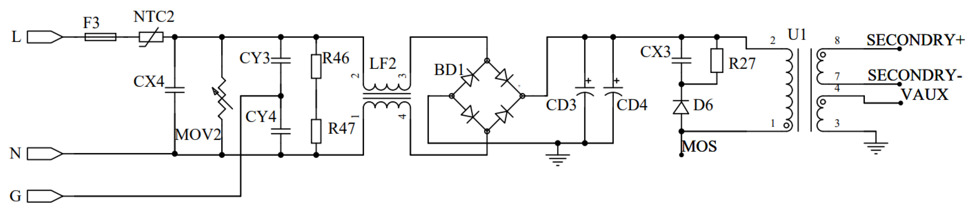
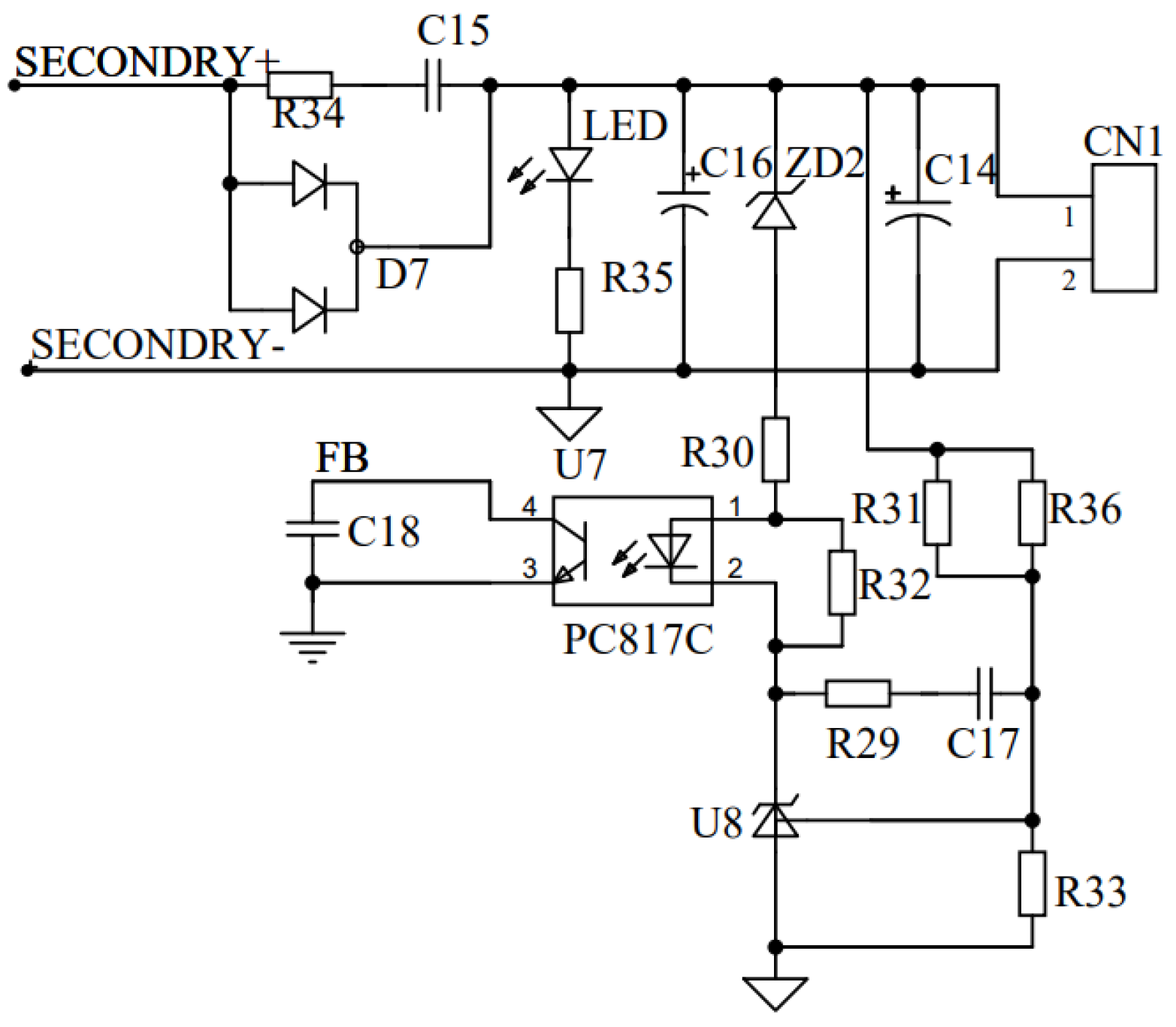
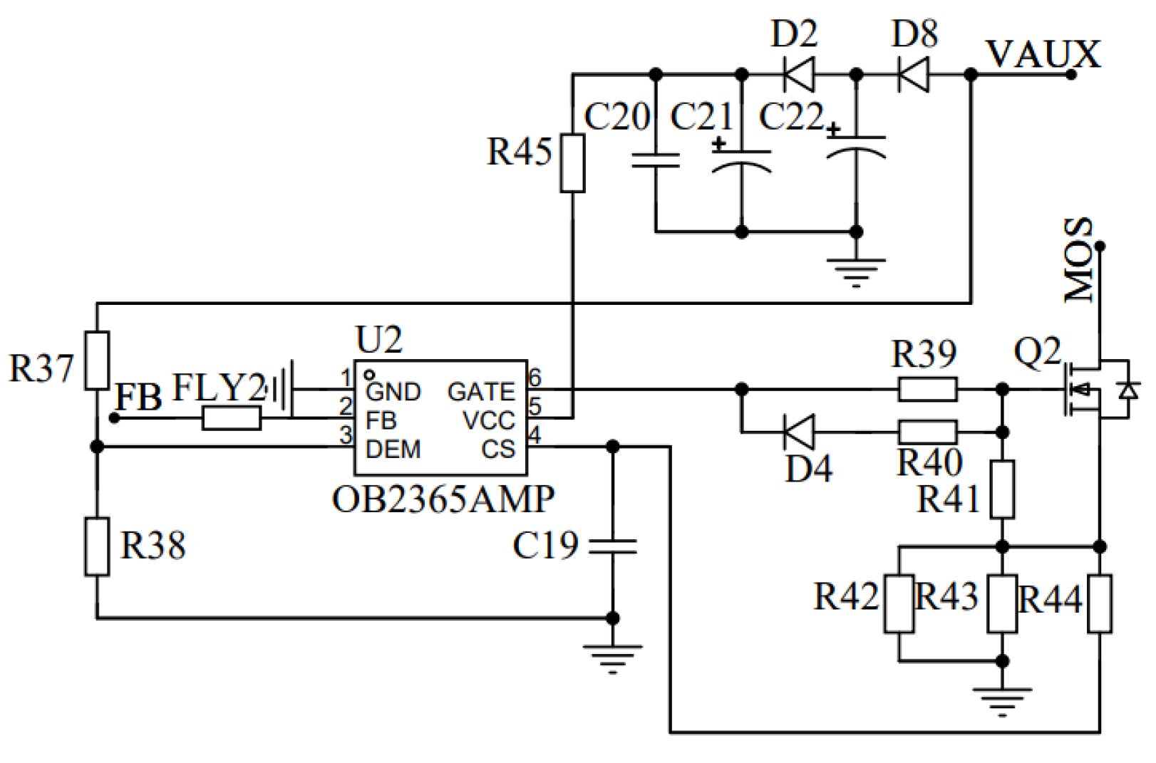
2.3. Switching Power Supply
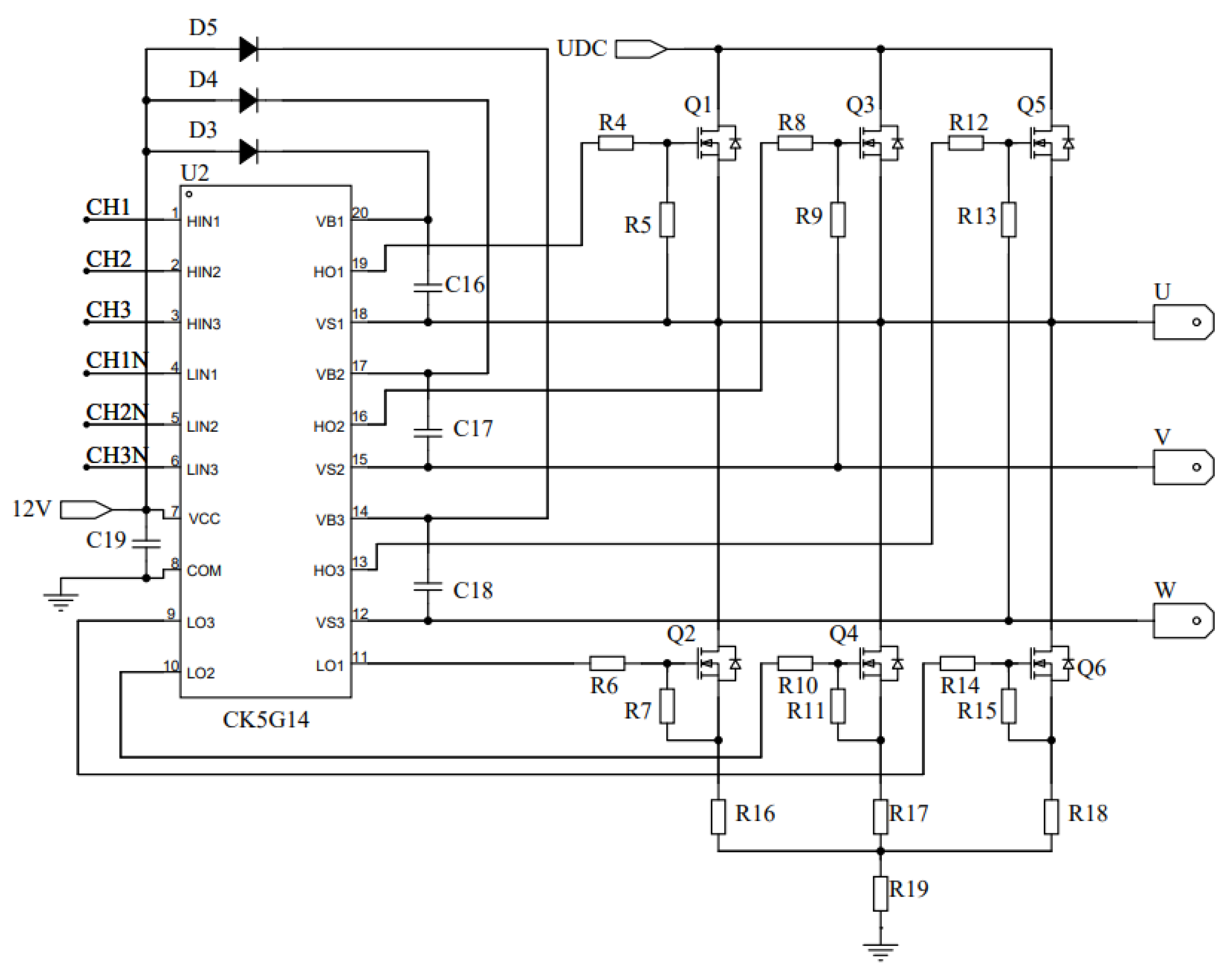
To provide a stable and safe 36 V output, a flyback switch-mode power supply was designed. The switch-mode power supply circuits are shown in Figure 2, Figure 3 and Figure 4.
As shown in Figure 2, the high-voltage circuit in the switch-mode power supply begins with the 220 V AC input. First, it passes through the electromagnetic interference (EMI) filter circuit to suppress and filter out the electromagnetic interference generated by the power supply, ensuring the normal operation of the power supply and its connected devices. A fuse is also included; it will blow if the current is too high, effectively protecting the circuit from damage. Next, the AC power enters a full-bridge rectifier circuit composed of four diodes, and after filtering through capacitors, it is converted from AC to DC. To protect the MOSFET from transient voltage spikes when it is turned off, an RCD snubber circuit is incorporated into the design. The RCD circuit, consisting of a resistor, capacitor, and diode, absorbs and dissipates transient voltage spikes, effectively preventing over-voltage damage to the MOSFET. Then, the high voltage is converted to low-voltage electricity through the transformer, which also provides electrical isolation between the high-voltage and low-voltage sections.
As shown in Figure 3, after conversion by the transformer, the voltage is reduced to low voltage. To reduce ripple, a filter capacitor is added to the circuit, resulting in a final output of 36 V DC. To stabilize the output voltage, a feedback circuit is used to relay changes in output voltage to the control chip OB2365. The chip adjusts the PWM waveform’s duty cycle based on the feedback signal, precisely regulating the output voltage to maintain it within the desired range.
As shown in Figure 4, the low voltage from the transformer is used to power the chip through rectification and filtering by diodes and capacitors. The OB2365 chip generates a PWM waveform by controlling the switching of the MOSFET.

2.4. Driver Circuit

This article designs a three-phase brushless DC motor driver circuit based on the CK5G14 gate driver chip, as shown in Figure 5 and Figure 6.
As shown in Figure 5, the BL935936 buck converter chip is used to step down the 36 V DC to 12 V DC to power the three-phase gate driver chip.
As shown in Figure 6, the three-phase gate driver chip controls the switching of six MOSFETs, while the 36 V DC serves as the bus voltage for the motor. The inverter circuit, consisting of six MOSFETs, converts the DC voltage into AC voltage, controlling the motor’s operating speed by varying the amplitude and frequency of the three-phase AC voltages U, V, and W.

3. Mathematical Model

To ensure the smooth and reliable operation of the system during the initial startup phase, the current-frequency (I-F) control method is used.
First, the motor is started, and then it switches to a sensorless control method. Before starting the motor, the rotor position needs to be pre-positioned. Assume the I-F coordinate axes are d*-q*, with an angular difference θ e between the d-q axis and the d*-q* axis. During the pre-positioning process, a suitable value of i q is set based on the I-F coordinate axes, with i d = 0 . The torque is used to pull the rotor in the d-axis direction towards the q* axis, and simultaneously θ e = 0 . At this point, positioning is complete, and the motor remains stationary. Then, by adjusting θ e the motor can be made to rotate.
Since the direct axis and quadrature axis inductances are equal for surface-mounted motors (Ld = Lq), the electromagnetic torque can be expressed as follows:
T e = 3 2 p n ψ f i q cos θ e ,
According to Equation (1), during the switching process, it is necessary to avoid excessive or insufficient electromagnetic torque to prevent torque pulsation and speed fluctuations. Therefore, the optimal switching torque must be determined, which involves selecting an appropriate i q cos θ e .
Before switching, the q-axis current in the d-q axis is calculated using the following formula:
i q r e a l = i q θ ^ e θ e ,
where θ ^ e is the angle of the observer.
To smoothly transition from I-F control to observer control, a switching function is used [16], which is defined as follows:
ζ = 1 ω i f ω 1 , cos ω i f ω 1 ω 2 ω 1 π 2 ω 1 ω i f ω 2 , 0 ω i f ω 2 ,
where ω1 and ω2 are the electrical angular velocities at the start and end of the switching process, respectively, while ωif is the electrical angular velocity output from the I-F controller.
During the switching process, to maintain the optimal torque, the corresponding reference current I q can be expressed as follows:
I q = i q r e a l cos ζ θ e ,
The application of sensorless control technology can effectively reduce costs, simplify maintenance, and save installation space. Sensorless control reduces potential issues introduced by sensors, especially lowering the likelihood of failures in harsh environments [17,18]. The flux observer is a control method that decouples rotor position information from the magnetic flux of the motor rotor. Compared to other observers, the flux observer is relatively simple to compute, requires fewer parameters to be adjusted, has low computational complexity, and provides a fast response. Additionally, this observer performs well even at low speeds [19,20]. The design of the nonlinear flux linkage observer algorithm is based on establishing a mathematical model in the α-β coordinate system, rewriting the motor’s voltage equation as follows:
The flux observer algorithm design is based on the mathematical model established in the α-β coordinate system. The motor’s voltage equations are rewritten as follows:
U α = R s i α + p i α L s ω e ψ f sin θ e , U β = R s i β + p i β L s + ω e ψ f cos θ e ,
where Uα and Uβ are the stator voltages along the α and β axes, iα and iβ are the stator currents along the α and β axes, θe is the electrical angle.
The flux equations of the surface-mounted motor in the α-β coordinate system, after performing the Park inverse transform, become the following:
ψ α = L s i α + ψ f cos θ e , ψ β = L s i β + ψ f sin θ e ,
where ψα and ψβ are the flux of the stator on the α and β axes.
The state variables are defined as follows:
x = x 1 x 2 ,   y = y 1 y 2 ,   cause x 1 = ψ α x 2 = ψ β ,   y 1 = p i α L s ω e ψ f sin θ e y 2 = p i β L s + ω e ψ f cos θ e
Combining Equations (5) and (6) results in the following formula:
x 1 = L s i α + ψ f cos θ e , x 2 = L s i β + ψ f sin θ e ,
y 1 = U α R s i α , y 2 = U β R s i β ,
Combining Equations (7) and (8) results in the following formula:
x ˙ 1 = y 1 = p i α L s ω e ψ f sin θ e , x ˙ 2 = y 2 = p i β L s + ω e ψ f cos θ e ,
The observer equation is defined as follows:
x ^ ˙ 1 = y 1 + k x ^ 1 L s i α ψ f 2 x ^ 1 L s i α 2 x ^ 2 L s i β 2 , x ^ ˙ 2 = y 2 + k x ^ 2 L s i β ψ f 2 x ^ 1 L s i α 2 x ^ 2 L s i β 2 ,
where k is the gain of the observer, x ^ 1 and x ^ 2 the state variable estimated for the observer, x ^ ˙ 1 and x ^ ˙ 2 the derivative of the state variable estimated for the observer.
According to fluid dynamics knowledge, the flow rate and head of a pump system are closely related to the motor’s speed. Therefore, increasing the pump motor’s speed improves the pump’s performance. In practical applications, the speed range of the motor is limited by the output voltage and current capability of the inverter. To achieve higher speeds, an advanced angle flux-weakening control is used, which involves increasing the stator’s negative direct-axis demagnetizing current component to maintain voltage balance during high-speed operation, thus achieving flux weakening and increasing the motor rotor speed to enhance the pump’s performance [21].
When the PMSM is operating stably, the stator voltage drop can be neglected, and the voltage equation is as follows:
L q i q 2 + L d i d + ψ f 2 = U Max ω e 2 ,
where U Max = U d c / 3 represents the stator phase voltage, which is the maximum output voltage allowed by the inverter, and Udc is the DC bus voltage.
For SPMSM operating below the rated speed, an id = 0 control strategy is used. The relationship between the d-q axis components of the stator current is given as follows:
i d i q = i s sin θ e cos θ e ,
where is is the amplitude of the stator current, θe is the synchronous rotation angle.
The critical speed of the motor is defined as follows:
ω e = U Max L q i q 2 + L d i d + ψ f 2
When the PMSM speed exceeds the rated speed, lead-angle field-weakening control is adopted. The d-axis and q-axis current components are redistributed by changing the current vector angle θe, which alters the d-axis and q-axis currents. During operation, the stator current components on the d-q axis satisfy the following relationship:
i d i q = i s sin θ e + Δ θ e cos θ e + Δ θ e .
where Δθe is the flux-weakening advance angle, which provides a positive phase shift angle. In this case, id = is*sinθe < 0.
During the flux-weakening speed control process, there must be a limit on the current id. The maximum demagnetizing current idmax is given by idmax = ψf/Ld, while the maximum stator current imax is determined by the capabilities of the drive circuit and motor. Thus, the conditions for limiting idid during flux-weakening control are as follows: if idmax < imax, then id = idmax; if idmaximax, then id = imax.
The flux-weakening control framework for a PMSM with no reluctance is shown in Figure 7. Before starting the motor, pre-positioning is performed first, and then the system smoothly switches to observer control based on the I-F control strategy. The system starts with an initial speed ωr. The flux-weakening control module determines appropriate d-axis and q-axis currents idr and iqr based on the speed. The corresponding voltages Udr and Uq are transformed into Uαr and Uβr using the inverse Park transformation. These voltages are then converted into time-varying PWM signals through Space Vector Pulse Width Modulation (SVPWM). Finally, the inverter generates U, V, W three-phase AC voltage signals to drive the three-phase motor. The motor current is sampled through dual resistors to obtain the three-phase currents ia, ib and ic using the Clarke transform. These three-phase currents are transformed into iα and iβ via the Clark transformation. The obtained stator voltages Uαr and Uβr, along with the sampled stator currents iα and iβ, are used as inputs to the flux observer. The system uses these inputs to estimate the rotor position and speed, replacing the need for rotor position and speed sensors. The estimated motor speed is fed back into the system and input into a proportional–integral–derivative (PID) controller. The PID controller adjusts the P, I, and D values to achieve sensorless speed control of the PMSM.

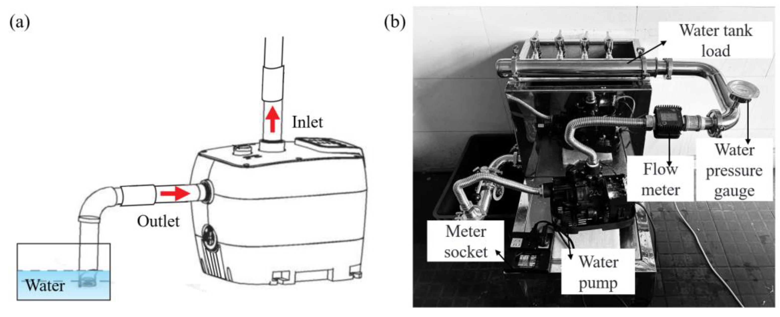
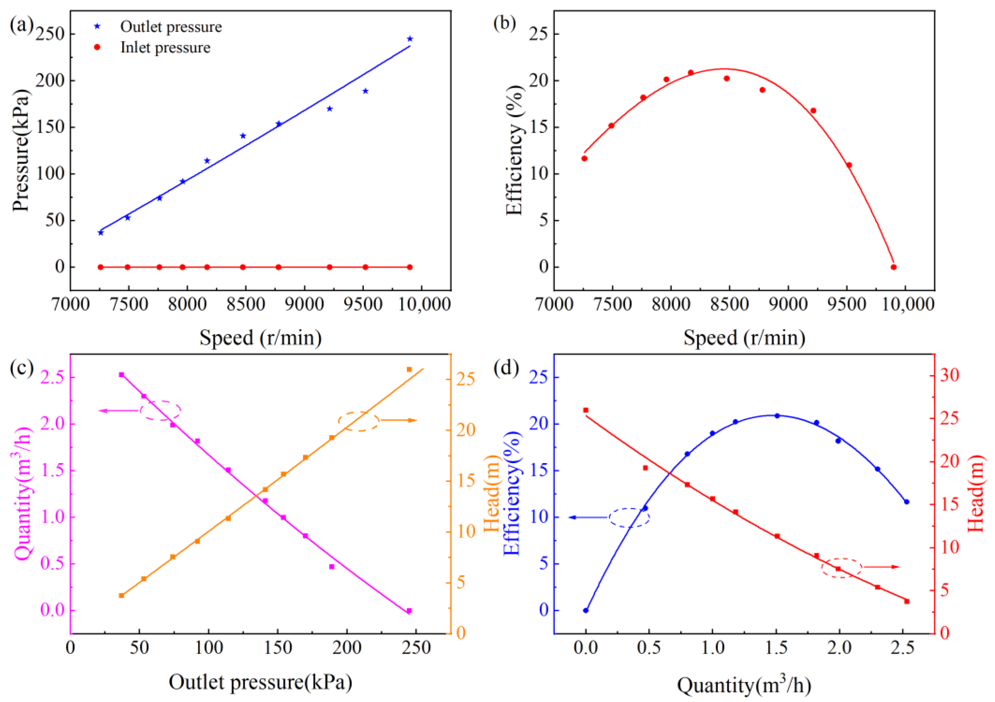
4. Experimental Results and Analysis

To better validate the practicality and reliability of the switch-mode power supply, we built a switch-mode power supply experimental platform as shown in Figure 8. The platform includes a switching power supply, an electronic load, a programmable power supply, an oscilloscope, and an AC/DC parameter tester.
A switched-mode power supply with a rated voltage of 36 V and a rated current of 3.6 A was selected as the power source for the PMSM low-voltage water pump. The test data for the power supply are presented in Table 2. The test results indicate that at an input voltage of 220 V, the power supply achieves an efficiency of 89.6%, a linear adjustment rate of less than 1%, a load regulation of less than 1%, and a ripple of less than 500 mV. These results demonstrate that the selected power supply has excellent performance, making it a suitable choice for powering the PMSM low-voltage water pump.
To further validate the correctness and practicality of the control algorithm, it is applied to a PMSM low-voltage water pump. The experimental test system is shown in Figure 9. Figure 9a illustrates the installation schematic of the water pump. Before performing the installation, it is essential to ensure that the power supply is disconnected. During installation, the inlet pipe should be connected to the water pump’s inlet, and the outlet should be connected to a water pipe equipped with a valve. After installation, it is necessary to ensure that the piping is fully sealed and to carefully check all connections for any signs of leakage. Figure 9b shows the water pump test platform, which includes a digital power meter, a water pump, a digital flow meter, a precision pressure gauge, and a water tank. The measurement equipment and its accuracy are listed in Table 3.
According to GB/T 3216—2016 [22], the calculation formula for pump efficiency is as follows:
η = ρ g Q H 3600 P a ,
where ρ is the density of water, g is the acceleration due to gravity, Q is the flow rate, H is the head, and Pa is the shaft power.
The calculation formula for shaft power is as follows:
P a = 3 U I cos ϕ
where U is the voltage, I is the current, and cosϕ is the power factor.
During the water pump performance testing process, key parameters such as head, flow rate, and pressure were recorded under different conditions, and the water pump performance curves were plotted as shown in Figure 10. The speed and pressure curves are illustrated in Figure 10a. Due to the design of the water pump’s inlet pipe, the inlet pressure is 0 kPa. As the speed gradually increases, the outlet pressure increases proportionally. The speed and efficiency curves are shown in Figure 10b. As the speed increases from 7260 r/min to 9900 r/min, the pump’s efficiency initially increases and then decreases, reaching its maximum at a speed of 8168 r/min, which indicates the optimal operating point of the pump. The outlet pressure versus flow rate and head curves are depicted in Figure 10c. As the outlet pressure increases from 37 kPa to 245 kPa, the head increases linearly, while the flow rate decreases from 2.53 m3/h to 0 m3/h, showing an inverse relationship. The flow rate versus head and efficiency curves are shown in Figure 10d. As the pump’s flow rate increases from 0 m3/h to 2.5 m3/h, the head decreases linearly, from an initial 26.01 m down to 3.77 m. The system efficiency follows a parabolic trend with flow rate, reaching its maximum value of 20.86% at a flow rate of 1.51 m3/h. Based on the test results, it can be concluded that the PMSM low-voltage pump, with an input voltage of 36 V, a current of 3.6 A, a maximum pressure of 255 kPa, a maximum head of 26 m, and a maximum flow rate of 2.5 m3/h, demonstrates good performance.
To better showcase the performance advantages of the PMSM low-voltage pump, Table 4 compares the PMSM low-voltage pump with other types of pumps. The approximate data for the pumps are shown in Table 4, under conditions of lower input power, the PMSM low-voltage pump exhibits higher head and system efficiency compared to other types of pumps. This further demonstrates the energy-saving and high-efficiency characteristics of the PMSM low-voltage pump.

5. Conclusions

In view of the potential safety hazards caused by the traditional metal pump that generally uses high-voltage drives, a solution is proposed that uses lightweight plastic instead of metal as the structural material of the pump and converts the 220 V high voltage to 36 V of safe voltage to drive the pump. This significantly reduces the risk of electric shock and improves the safety of the pump system. In this study, PMSM was selected as the core drive for the pump, replacing the traditional IM. Combined with sensorless control and weak field control strategies, the overall performance of the pump was further improved. The test results show that the proposed PMSM low-voltage pump performs well compared with other types of pumps. In future work, we will extend the impact on pump performance to changes in the pump’s structure or control algorithms.

Author Contributions

Conceptualization, X.J., L.Z., T.L. and Y.J.; methodology, X.J., T.L. and Y.J.; software, X.J. and Y.J.; validation, X.J. and Y.J.; formal analysis, X.J.; investigation, X.J.; resources, X.J., T.L. and Y.J.; data curation, L.Z.; writing—original draft preparation, X.J. and L.Z.; writing—review and editing, T.L. and Y.J.; visualization, X.J.; supervision, T.L.; project administration, Y.J.; funding acquisition, T.L. All authors have read and agreed to the published version of the manuscript.

Funding

This work was supported by the “Pioneer” and “Leading Goose” R&D Program of Zhejiang under Grant No.2023C01212.

Data Availability Statement

The data that support the findings of this study can be accessed upon reasonable request from the corresponding author.

Conflicts of Interest

The authors declare no conflicts of interest.

References

  1. Gan, X.; Pei, J.; Pavesi, G.; Yuan, S.; Wang, W. Application of intelligent methods in energy efficiency enhancement of pump system: A review. Energy Rep. 2022, 8, 11592–11606. [Google Scholar] [CrossRef]
  2. Kashif, M.; Singh, B. Modified active-power MRAS based adaptive control with reduced sensors for PMSM operated solar water pump. IEEE Trans. Energy Convers. 2022, 38, 38–52. [Google Scholar] [CrossRef]
  3. Kim, S.I.; Im, J.H.; Song, E.Y.; Kim, R.Y. A new rotor position estimation method of IPMSM using all-pass filter on high-frequency rotating voltage signal injection. IEEE Trans. Ind. Electron. 2016, 63, 6499–6509. [Google Scholar] [CrossRef]
  4. Shen, H.; Zhang, C. A new efficient sensorless I/f control method for IPMSM drives. In Proceedings of the 2017 IEEE 26th International Symposium on Industrial Electronics (ISIE), Edinburgh, UK, 19–21 June 2017; pp. 209–213. [Google Scholar]
  5. Bolognani, S.; Tubiana, L.; Zigliotto, M. Extended Kalman filter tuning in sensorless PMSM drives. In Proceedings of the Power Conversion Conference-Osaka 2002 (Cat. No. 02TH8579), Osaka, Japan, 2–5 April 2002; Volume 1, pp. 276–281. [Google Scholar]
  6. Lu, H.; Wu, J.; Li, M. A new sliding mode observer for the sensorless control of a PMLSM. In Proceedings of the 2017 29th Chinese Control and Decision Conference (CCDC), Chongqing, China, 28–30 May 2017; pp. 5364–5369. [Google Scholar]
  7. Lai, C.; Feng, G.; Tian, J.; Li, Z.; Zuo, Y.; Balamurali, A.; Kar, N.C. PMSM drive system efficiency optimization using a modified gradient descent algorithm with discretized search space. IEEE Trans. Transp. Electrif. 2020, 6, 1104–1114. [Google Scholar] [CrossRef]
  8. Bai, S. Flux-weakening control of permanent magnet synchronous motor using leading angle. In Proceedings of the 2011 International Conference on Electrical Machines and Systems, Beijing, China, 20–23 August 2011; pp. 1–5. [Google Scholar]
  9. Algarny, K.; Abdelrahman, A.S.; Youssef, M.Z. Performance comparison between induction and permanent magnet synchronous electric machines in water pump application. In Proceedings of the European Conference on Electrical Engineering and Computer Science, Bern, Switzerland, 20–22 December 2018; pp. 165–169. [Google Scholar]
  10. Zamudio-Ramírez, I.; Osornio-Ríos, R.A.; Antonino-Daviu, J.A.; Quijano-Lopez, A. Smart-sensor for the automatic detection of electromechanical faults in induction motors based on the transient stray flux analysis. Sensors 2020, 20, 1477. [Google Scholar] [CrossRef] [PubMed]
  11. Wankhede, A.K.; Pal, S.; Singh, M.; Gogte, O.R.; Sharma, A.; Fernandes, B.G. Development of Efficient 5-HP BLDC motor for Solar water pump and performance comparison with Induction Motor counterpart. In Proceedings of the 2021 IEEE India Council International Subsections Conference (INDISCON), Nagpur, India, 27–29 August 2021; pp. 1–4. [Google Scholar]
  12. Wang, Q.; Wang, S.; Chen, C. Review of sensorless control techniques for PMSM drives. IEEJ Trans. Electr. Electron. Eng. 2019, 14, 1543–1552. [Google Scholar] [CrossRef]
  13. Chen, H.; Demerdash, N.A.; El-Refaie, A.M.; Guo, Y.; Hua, W.; Lee, C.H. Investigation of a 3D-magnetic flux PMSM with high torque density for electric vehicles. IEEE Trans. Energy Convers. 2021, 37, 1442–1454. [Google Scholar] [CrossRef]
  14. Ullah, K.; Guzinski, J.; Mirza, A.F. Critical review on robust speed control techniques for permanent magnet synchronous motor (PMSM) speed regulation. Energies 2022, 15, 1235. [Google Scholar] [CrossRef]
  15. Li, Z.; Wang, F.; Ke, D.; Li, J.; Zhang, W. Robust continuous model predictive speed and current control for PMSM with adaptive integral sliding-mode approach. IEEE Trans. Power Electron. 2021, 36, 14398–14408. [Google Scholar] [CrossRef]
  16. Liu, L.; Jin, D.; Si, J.; Liang, D. A novel nonsingular fast terminal sliding mode observer combining I-F method for wide-speed sensorless control of PMSM drives. IET Power Electron. 2023, 16, 843–855. [Google Scholar] [CrossRef]
  17. Zhang, M.; Xia, B.; Zhang, J. Parameter design and convergence analysis of flux observer for sensorless pmsm drives. IEEE Trans. Energy Convers. 2022, 37, 2512–2524. [Google Scholar] [CrossRef]
  18. Yu, B.; Shen, A.; Chen, B.; Luo, X.; Tang, Q.; Xu, J.; Zhu, M. A compensation strategy of flux linkage observer in SPMSM sensorless drives based on linear extended state observer. IEEE Trans. Energy Convers. 2021, 37, 824–831. [Google Scholar] [CrossRef]
  19. Liu, J.; Zhang, Y. Performance improvement of nonlinear flux observer for sensorless control of PMSM. IEEE Trans. Ind. Electron. 2023, 70, 12014–12023. [Google Scholar] [CrossRef]
  20. Ortega, R.; Praly, L.; Astolfi, A.; Lee, J.; Nam, K. Estimation of rotor position and speed of permanent magnet synchronous motors with guaranteed stability. IEEE Trans. Control Syst. Technol. 2010, 19, 601–614. [Google Scholar] [CrossRef]
  21. Zhang, Z.; Wang, C.; Zhou, M.; You, X. Flux-weakening in PMSM drives: Analysis of voltage angle control and the single current controller design. IEEE J. Emerg. Sel. Top. Power Electron. 2018, 7, 437–445. [Google Scholar] [CrossRef]
  22. GB/T 3216-2016; Rotodynamic Pumps–Hydraulic Performance Acceptance Tests—Grades 1, 2 and 3. State Administration for Market Regulation, Standardization Administration of PRC: Beijing, China, 2016.
  23. Emiliawati, A. A study of water pump efficiency for household water demand at Lubuklinggau. In Proceedings of the AIP Conference Proceedings, Provo, UT, USA, 16–21 July 2017; Volume 1903. [Google Scholar]
  24. Quoilin, S.; Van Den Broek, M.; Declaye, S.; Dewallef, P.; Lemort, V. Techno-economic survey of Organic Rankine Cycle (ORC) systems. Renew. Sustain. Energy Rev. 2013, 22, 168–186. [Google Scholar] [CrossRef]
  25. Walski, T.; Zimmerman, K.; Dudinyak, M.; Dileepkumar, P. Some surprises in estimating the efficiency of variable-speed pumps with the pump affinity laws. In Proceedings of the World Water & Environmental Resources Congress 2003, Philadelphia, PA, USA, 23–26 June 2003; pp. 1–10. [Google Scholar]
Figure 1. Exploded view of the PMSM pump structure.
Electronics 13 03674 g001
Figure 2. High-voltage circuit.
Electronics 13 03674 g002
Figure 3. Output feedback circuit.
Electronics 13 03674 g003
Figure 4. Main chip circuit.
Electronics 13 03674 g004
Figure 5. Buck converter circuit.
Electronics 13 03674 g005
Figure 6. PMSM low-voltage drive circuit.
Electronics 13 03674 g006
Figure 7. PMSM non-inductive weak field control framework.
Electronics 13 03674 g007
Figure 8. Switching power supply test system.
Electronics 13 03674 g008
Figure 9. Experimental test system. (a) Installation schematic; (b) water pump test system.
Electronics 13 03674 g009
Figure 10. Pump performance curve. (a) The relationship between rotational speed and pressure; (b) the relationship between velocity and efficiency; (c) the relation of outlet pressure to flow rate and head; (d) the relation of flow rate to head and the efficiency.
Electronics 13 03674 g010
Table 1. PMSM parameter table.
ParameterSymbolsValues
Rated power kwP0.13
Rated speed r·min−1N3000
Rated voltage vV36
Rated current AI3.6
Polepairspn2
Stator resistance ΩRs0.525
Magnetic flux Wbψf0.01154
Stator inductance mHLd1.683
Stator inductance mHLq1.683
Table 2. Switching power supply test data.
Input Voltage
V
Linear Adjustment Rate
%
Load Regulation
%
Ripple
mV
Efficiency
%
1200.580.31<50086.4
2200.380.28<50089.6
2600.330.11<50089.7
Table 3. Measurement instruments and their accuracy.
Measured ParameterInstrumentAccuracy
Flow rateDigital Flowmeter±5%
PressurePrecision Pressure Gauge±0.4%
Voltage and PowerDigital Power Monitor±1%
SpeedCurrent clamp±2%
Table 4. The comparison of the PMSM low-voltage water pump and other water pumps proposed in this paper.
Types of PumpsVoltage
V
Flow Rate
m3/h
Head
m
Power
kw
Speed
r·min−1
Maximum Efficiency
%
Squirrel Cage Induction Motor Pump219.12.0260.20327769.39
Single Phase AC Motor Pump221.81.19110.24029858.58
Thermal
Shallow well
Water pump [23]
2201.2314.60.290/12.2
Diaphragm piston pump [24]/////15
Phase TEFC motor [25]2301.810.6//15.1
This work36.01.5111.40.130816820.87
Disclaimer/Publisher’s Note: The statements, opinions and data contained in all publications are solely those of the individual author(s) and contributor(s) and not of MDPI and/or the editor(s). MDPI and/or the editor(s) disclaim responsibility for any injury to people or property resulting from any ideas, methods, instructions or products referred to in the content.

