Article

Control Method for Ultra-Low Frequency Oscillation and Frequency Control Performance in Hydro–Wind Power Sending System

by
Renjie Wu
1,
Qin Jiang
1,
Baohong Li
1,*,
Tianqi Liu
1 and
Xueyang Zeng
2
1
College of Electrical Engineering, Sichuan University, Chengdu 610065, China
2
State Grid Sichuan Electrical Power Research Institute, Chengdu 610041, China
*
Author to whom correspondence should be addressed.
Electronics 2024, 13(18), 3691; https://doi.org/10.3390/electronics13183691
Submission received: 15 August 2024 / Revised: 12 September 2024 / Accepted: 15 September 2024 / Published: 17 September 2024

Abstract

:
In a hydropower-dominated power grid, the primary frequency regulation (PFR) capability of hydropower units is typically compromised to suppress ultra-low frequency oscillations (ULFOs). However, as renewable wind power is further integrated, a practicable solution to damp ULFOs has emerged, which is to adjust the frequency control parameters of wind turbine (WT) units. Driven by the goals of overall damping enhancement and ULFO suppression, this paper first establishes an extended unified frequency model (EUFM) of a hydro–wind power sending system. Based on EUFM, the damping torque of the hydro–wind power sending system is derived, and the specific impact of WT control parameters on ULFOs and PFR characteristics is investigated. Then, a novel optimization objective function considering damping in the ultra-low frequency band and PFR is formulated and solved using an intelligence algorithm. By optimizing the parameters of the WT to suppress ULFOs, the PFR capability of hydropower units can be released. Finally, simulation results verify that the optimized WT parameters can simultaneously address the ULFO problem and guarantee PFR performance, thereby enhancing the frequency dynamic stability of the sending system.

1. Introduction

In the past decade, in the hydropower-dominated power grid, which is asynchronous interconnecting through a back-to-back high-voltage DC (HVDC) transmission system, ultra-low frequency oscillations (ULFOs) have occurred multiple times in China [1]. Unlike traditional low-frequency oscillations (LFOs) in power systems, ULFOs manifest as the frequency of the whole units oscillating in the same mode, which means there are no relative oscillations between generator rotors [2]. There is a common sense that ULFOs are within the scope of frequency stability issues, characterized by long oscillation periods and extremely low oscillation frequencies (less than 0.1 Hz), posing a significant threat to the safe and stable operation of power systems [3].
The current research mainly focuses on asynchronous interconnected or islanded hydropower grids. From a mechanistic perspective, studies have indicated that the main reason for the occurrence of ULFOs is the inability of hydropower units to provide sufficient damping torque within the ultra-low frequency band (0~0.1 Hz) [4]. To find out the specific factors, reference [5] investigates the governing system’s parameters, and in [6], the PID controller of the governing system and its parameters are given in detail. The above studies indicate that the damping level of the system is determined by the proportional and integral coefficients of the PID controller as well as the water starting time. In addition to damping level, thermal power ratio and dead zone setting are crucial to affect the oscillation mode of ULFOs [7,8].
Currently, methods to suppress ULFOs mainly include optimizing the parameters of the hydro turbine (HT) governor and additional damping control. Reasonably increasing the ratio of governor proportional and integral gain can enhance damping to suppress ULFOs [9]. Based on this, in [10], a parameter design method for HT governors is proposed using the structural singular value theory. In [11], deep learning algorithms are applied to ensure the effectiveness of the optimized PID parameters for various extreme operating conditions. Additionally, a parameter optimization strategy is suggested in [12], which considers both damping characteristics and PFR of hydropower units, aiming to suppress ULFOs by optimizing the parameters of hydropower unit governor systems. Based on these findings, reference [13] proposed a CFS_GPSS strategy to compensate phase and increase system damping, which enhances PFR performance while suppressing ULFO. However, the above methods have weakened the PFR ability of hydropower units, resulting in a weakened ability of the power grid to resist active power shocks.
In the realm of additional damping control, power system stabilizers (PSS) are commonly utilized for mitigating LFOs [14]. However, traditional PSS are unable to suppress ULFOs. Therefore, reference [15] suppresses ULFOs through PR-PSS control. Reference [16] demonstrates through small signal analysis that GPSS control has a suppressive effect on ULFOs and optimizes appropriate parameters to suppress ULFOs. Furthermore, in [17], the crossbreed operation in the genetic algorithm is introduced to the particle swarm optimization (PSO) algorithm to form a hybrid PSO so as to optimize PSS4B parameters; the optimized PSS4B can provide effective damping in different frequency bands. Additionally, the ability of DC transmission to provide frequency support is explored [18]. DC additional control has also been applied for the suppression of ULFOs, such as a frequency limiting controller (FLC) [19] and a damping controller [20].
In recent years, with the significant integration of wind power into the power system, wind power has played an increasingly crucial role in ensuring the safe and stable operation of the power system [21]. Therefore, in many countries, wind farms are required to be equipped with PFR controllers. The participation of wind turbines in the primary frequency regulation of the system requires the use of auxiliary frequency regulation control links, which can be divided into two methods: power shedding control [22] and rotor kinetic energy control [23]. Additional frequency controllers are designed to meet strict frequency regulation requirements to ensure sufficient frequency and power support against load disturbances. A previous study [24] optimizes the parameters of WT with the PFR performance of WT participating in PFR as the goal. However, the design process did not consider the damping of ULFOs, potentially leading WT to provide negative damping in the ultra-low frequency band, exacerbating the threat of ULFOs in certain circumstances. Hence, in power grids with a high proportion of hydropower at the sending end, it is necessary to readjust the frequency control parameters of WT to reduce the risk of ULFOs. Reference [25] reveals the dynamic behavior of WT and its interference mechanisms with HT, explaining the system’s ULFO modes. It also analyzes the impact of different parameters of WT in various operating modes on ULFOs, indicating that different parameters have varying degrees of suppression on ULFOs. Furthermore, reference [26] investigates the issue of ULFOs in wind-hydro hybrid systems, demonstrating that WT can alleviate ULFOs but has not optimized the best frequency control parameters.
To fill the gap on additional control of ULFO based on renewable energy, this paper aims to explore the considerable potentiality in terms of both ULFO suppression and PFR performance of WT units. The contributions include the following three parts:
(1)
For ULFO mechanism analysis, an EUFM considering hydropower and wind units is established. The damping torque coefficients of the hydro–wind power system are derived.
(2)
Another effort is to reveal the detailed influence of WT frequency control parameters on frequency characteristics. In this aspect, the damping level and key performance indicators of PFR are investigated.
(3)
From the perspective of ULFO suppression by fulfilling the damping control potential of wind units. An optimization model of WT control parameters is established. The objective function balances both ULFO suppression and PFR performance, which is solved by the PSO algorithm. Then, the superior PFR performance of hydro units is profitable.
The organization of this paper is as follows: Section 2 establishes the EUFM of the hydro–wind sending system. Section 3 investigates the influence of WT frequency control parameters on damping characteristics and frequency characteristics. Section 4 proposes an optimal control method of WT for damping enhancement and PFR improvement comprehensively. Section 5 simulates and validates the aforementioned analysis. Finally, the main conclusions are drawn in Section 6.

2. Extended Unified Frequency Model of Hydro–Wind System

The damping coefficients of the hydropower unit and DFIG in the ultra-low frequency range are derived using the damping torque method. Moreover, an extended unified frequency model of hydropower and WT units is established to analyze the overall damping coefficient of the system in this section.

2.1. The Model of Hydropower Unit

It is convincingly proved that hydropower units would provide negative damping in the ultra-low frequency band. This is primarily attributed to the unique water hammer effect of HT and the FPR parameters of the governor. In that case, to simplify the analysis of hydropower units’ impact on ULFOs, we focus solely on the open-loop model of the governor and HT, as illustrated in Figure 1. The open-loop transfer function Gm(s) is derived as the multiplication of the transfer functions of the governor and HT, denoted as Ggov(s) and Gtur(s), which are defined by Equations (1) and (2), respectively.
G g o v ( s ) = ( K P T d + K D ) s 2 + ( K P + K I T d ) s + K I ( b p K P T d + b p K D + T d ) s 2 + ( b p K P + b p K I T d + 1 ) s + b p K I
where KP, KI, and KD are the proportional, integral, and differential coefficients of the PID governor, respectively; bp is the permanent slip coefficient.
G t u r ( s ) = 1 T w s 1 + 0.5 T w s
where Tw is the water starting time.
The complex torque coefficient (CTC) method is a common approach for ULFO analysis [27]. By determining the damping characteristics, the nature of ULFO modes can be easily characterized, and the adverse effects of the governor can be quantitatively assessed. Based on the CTC method, the transfer function Gm(s) can be decomposed in Δδ-Δω coordinate system, damping torque KDm, and synchronous torque KSm, as shown in Equation (3). Moreover, KDm is related to the ability to suppress oscillations and is mainly determined by the parameters of HT governor and water starting time, with the variation trend illustrated in Figure 2. Currently, in order to enhance the damping coefficient in the ultra-low frequency band of hydropower units, there is a general increase in the governor coefficient KP and a decrease in KI, leading to a decrease in the PFR capability of hydropower units. In the hydro–wind system, the damping torque of the WT can be increased to enhance the overall damping of the system, thereby releasing some of the PFR capability of the hydro turbine. Therefore, in Section 2.3, we established the EUFM to analyze the damping torque of the hydro–wind system.
G m ( s ) = Δ T m Δ ω = G gov ( s ) G t u r ( s ) = K Sm Δ δ + K Dm Δ ω

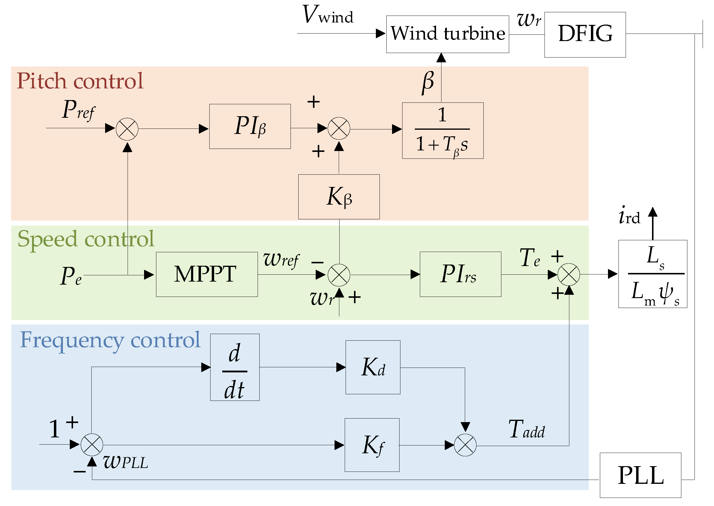
2.2. The Model of Doubly Fed Induction Generator

The WT discussed in this study are doubly fed induction generators (DFIGs), which are the most widely used wind turbines, consisting of a wound-type asynchronous generator with stator winding directly connected to a fixed-frequency three-phase power grid and a bidirectional back-to-back IGBT voltage source converter installed on the rotor winding. For DFIG with traditional power control methods, it is not feasible to respond to changes in system frequency. Thus, to make it possible for DFIG to participate in system frequency regulation, comprehensive inertia control is popular, including virtual inertia control (VIC) and droop control, by which the external characteristics of DFIG are closest to synchronous generators, as shown in Figure 3. It should be noted that Kd and Kf are the VIC coefficient and droop control coefficient, respectively. DFIG responds rapidly to frequency rate changes through the VIC while also adjusting the electromagnetic power of the WT through the droop control in response to system frequency deviations. In addition to frequency control, it also includes pitch angle control and speed control. When the wind speed changes, the tip speed ratio is adjusted by changing the WT speed to achieve maximum power tracking (MPPT). When the wind speed is higher than the set value, the maximum power is maintained through pitch angle control. These three parts constitute the main DFIG control system.
Similarly, based on the CTC method, the damping torque of the DFIG can be expressed as follows [26]:
D W = K d ω d 4 a i ( ω d 2 + b i ) 2 + ( ω d a i ) 2 + K f ω d 2 ( ω d 2 + b i ) ( ω d 2 + b i ) 2 + ( ω d a i ) 2
Under varying wind speed conditions, the operational mode of the WT varies, with ai and bi representing the coefficients in different modes.

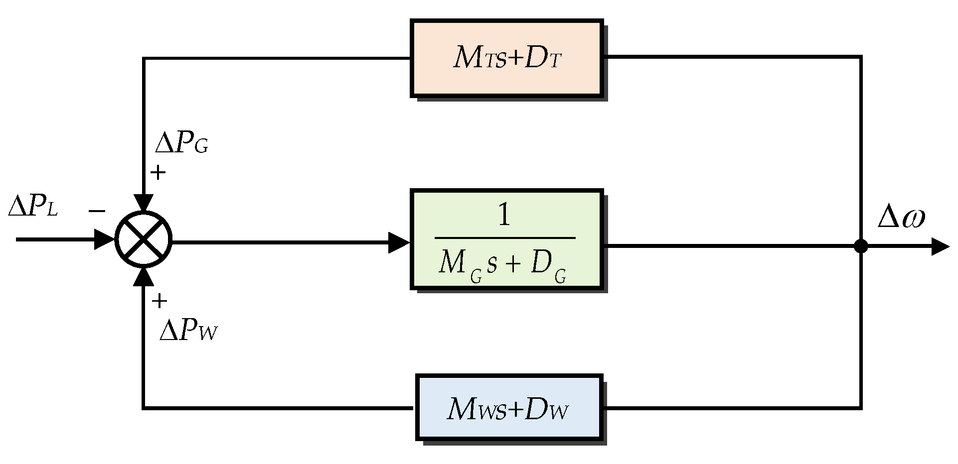
2.3. Extended Unified Frequency Model

The ULFO features longer oscillation periods and lower oscillation frequencies. Thus, it can be assumed that faster dynamic response processes such as rotor angle and AC voltage have decayed. Subsequently, the system frequency deviation is rather small [28]. In that case, based on the power characteristics of hydropower and wind units, respectively. We deduce an EUFM of hydro–wind sending system for ULFO analysis, which is illustrated in Figure 4. And ω is the system average frequency; PL is the system active load; PG and PW are the output active power of HT and WT units, respectively.
Based on EUFM, it can be derived as:
Δ P L Δ ω = ( M G + M W + M T ) s + ( D G + D W + D T )
where MG and DG are the equivalent inertia coefficient and damping coefficient of N hydropower units, respectively; MT and DT are the synchronous torque and damping torque of N HT units, respectively; MW and DW are the synchronous torque and damping torque of M WT units, respectively. In Equation (5), the summation of DG, DW, and DT represents the total damping torque of the system.
Based on the mechanism analysis, the occurrence of ULFOs is more likely when the damping torque value is negative. Most solutions focus on improving the damping torque of the hydro units by adjusting the governor parameters. However, it is disappointing that the PFR capability of the hydro units is simultaneously reduced, posing potential risks to frequency stability.

3. The Influence of DFIG on ULFO and PFR Performance

To enhance the overall damping torque in hydro–wind systems, increasing the WT’s damping torque DW has been identified as an effective strategy to mitigate ULFOs. At the same time, it is necessary to consider the frequency regulation of DFIG. This section mainly analyzes the influence of DFIG parameters on damping and PFR performance.

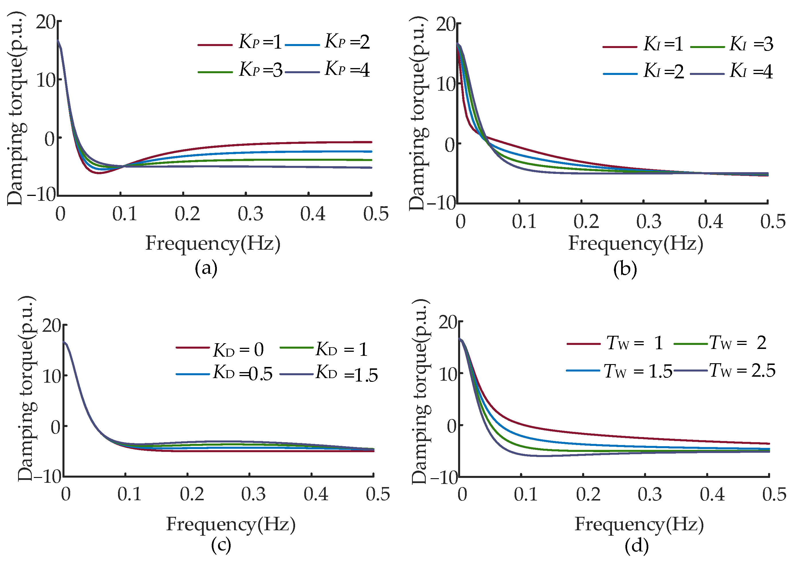
3.1. ULFO Damping Characteristics of DFIG

Based on the aforementioned analysis, the damping torque of DFIG is primarily related to VIC and droop control. At rated wind speed, the impact of Kd and Kf on the damping level in the ultra-low frequency band is illustrated in Figure 5.
It is obvious that in the ultra-low frequency band of 0–0.1 Hz, the VIC with larger Kd would provide a more severe negative damping effect. In contrast, the influence of droop control is delightful in the ultra-low frequency band; specifically, the larger Kf leads to a greater positive damping torque coefficient. Accordingly, to strengthen the damping in the ultra-low frequency band, a novel solution is to minimize Kd and increase Kf of DFIG.
However, regarding PFR performance, excessively small Kd may cause significant frequency rate changes and maximum frequency deviations. Conversely, an excessively large Kf may promote WT to release much rotor kinetic energy when participating in frequency regulation, resulting in severe secondary frequency drops during PFR, which we will discuss in Section 3.2. Therefore, it is essential to tune the parameters appropriately to balance the damping in the ultra-low frequency band and the performance of PFR.

3.2. PFR Performance of DFIG

The control methods for DFIG to participate in PFR include power load shedding control and rotor kinetic energy control. The former diminishes the economic viability of wind farms and burdens long-term economic losses. In this paper, we employ the later control for DFIG. To characterize the PFR performance of DFIG, the typical frequency response curve is illustrated in Figure 6; some important indicators, including the rate of change in frequency (RoCoF), maximum frequency deviation Δfmax1, and maximum secondary frequency drop deviation Δfmax2 are investigated. It should be noted that when the power grid oscillates at t0, DFIG conducts PFR from t0 and exits at toff, causing a secondary frequency drop while restoring rotor speed.

3.2.1. The Rate of Change in Frequency

The magnitude of RoCoF is dependent on system inertia and load increment, which can be expressed as:
RoCoF = Δ P L f 0 2 H s y s S b
where ΔPL is the system load increment, f0 is the initial frequency, Sb is the system capacity, and Hsys is the system equivalent inertia.
Moreover, Hsys can be expressed as:
H s y s = i = 1 N H i P i + j = 1 M H j P j S b
where N and M are the numbers of HT and WT, respectively; Hi and Hj are the inertia time constants of the i-th and j-th HT and WT, respectively; Pi and Pj are the capacities of the i-th and j-th HT and WT, respectively.
Generally, the virtual inertia time constant of DFIG is determined by the virtual inertia coefficient Kd. When the inertia time constant of HT remains constant, RoCoF decreases with an increase in Kd.

3.2.2. The Maximum Frequency Deviation

The maximum frequency deviation Δfmax1 of the system can be derived from the rotor motion equation [24], as shown in the specific formula Equations (8)–(14).
Δ f max 1 = 1 M e α ( π / 2 θ γ ) ω cos ( π / 2 γ ) C
α = T J + K d + K f T 1 2 T 1 ( T J + K f )
ω = K 1 + K f T 1 ( T J + K d ) α 2
M = Δ P L ω ( T J + K d ) K 1 K 1 + K f
θ = arccos [ ω ( T J + K d ) K 1 ( K 1 + K f ) ]
C = 1 Δ P L K 1 + K f
γ = arctan ( ω / α )
where TJ is the inertia constant of the hydropower unit; T1 and K1 are the coefficients of the identified low-order model of the WT governor.
The maximum deviation of system frequency with changes in DFIG parameters Kd and Kf is shown in Figure 7. It indicates that Kd and Kf can both reduce the maximum frequency deviation.

3.2.3. Maximum Secondary Frequency Drop Deviation

Besides RoCoF and maximum frequency deviation, it is worth mentioning that the risk of secondary frequency drop is also of great concern. Under rotor kinetic energy control, the DFIG can release rotor kinetic energy to provide active power support when the system frequency drops. Specifically, when Kf and Kd are larger, the output active power of DFIG during PFR will be greater, which means more rotor kinetic energy or PFR ability will be released. However, when the DFIG exits PFR, more active power will be absorbed from the power grid to restore the speed, resulting in a larger secondary frequency drop [29].
The secondary frequency drop Δfmax2 is determined as follows:
Δ f max 2 = 1 M 1 e α ( π / 2 θ γ ) ω cos ( π / 2 γ ) f o f f + Δ P u K 1
M 1 = Δ P u ω ( T J + K d ) K 1 K 1 + K f
The system frequency that DFIG exits PFR is given by:
f o f f = M e α ( t o f f t 0 ) cos [ ω ( t t 0 ) + θ ] + C
where ΔPu is the unbalanced power when the DFIG exits PFR.
When the PFR exiting time toff of DFIG is constant, the relationship between the secondary frequency drop with Kd and Kf is investigated in Figure 8. The deviation of the secondary frequency drop becomes severe when Kd increases from 0 to 20 and 40 to 60, while the impact is not significant between 20 and 40. The frequency drop initially decreases when Kf is 0~8, and it will increase with the larger Kf.

4. Comprehensive Control Optimization of DFIG for ULFO Suppression and PFR

DFIG provides a significant solution to support frequency control. This section presents a comprehensive parameter optimization method for DFIG engaged in balancing the damping of ULFOs and PFR performance.

4.1. Objective for ULFO Damping Control of DFIG

For ULFO suppression, the damping level is an important metric indicator. We propose the average value Df of the damping torque coefficient within a certain ultra-low oscillation frequency band, which is represented as:
D f = i = 1 n D W ( f i ) n
where n is the total number of frequency sampling points selected within the ultra-low oscillation frequency band; fi is the system frequency value of the i-th sampling point.
The objective function for ULFO damping control of DFIG can be concluded as follows:
{ A 1 ( K ) = D f K = [ K d , K f ]

4.2. Objective for PFR Performance of DFIG

In order to enhance the PFR performance, we put forward a PFR performance indicator A2(K), which comprehensively considers RoCoF, maximum frequency deviation, and maximum secondary frequency drop deviation, which is represented by Equation (20).
A 2 ( K ) = k 1 RoCoF + k 2 Δ f max + Δ
where k1 and k2 are the weights for RoCoF and total maximum frequency deviation, respectively; Δ is the penalty function; Δfmax is the larger value between the maximum frequency deviation and the maximum secondary frequency drop deviation, i.e., It is expressed in Equation (21).
Δ f max = max [ Δ f max 1 , Δ f max 2 ]
According to the Technical Requirements and Test Procedures for the PFR of WT in China [30], the PFR dynamic performance of WTs should meet the following requirements.
(1)
The lag time of PFR should not exceed 2 s;
(2)
The rise time of PFR should not exceed 9 s;
(3)
The adjustment time of PFR should not exceed 15 s;
To comply with the technical requirements and test procedures for PFR, when the WT parameters are designed unreasonably and do not meet the regulatory requirements, Δ is set to a large value to discard the set of parameters.

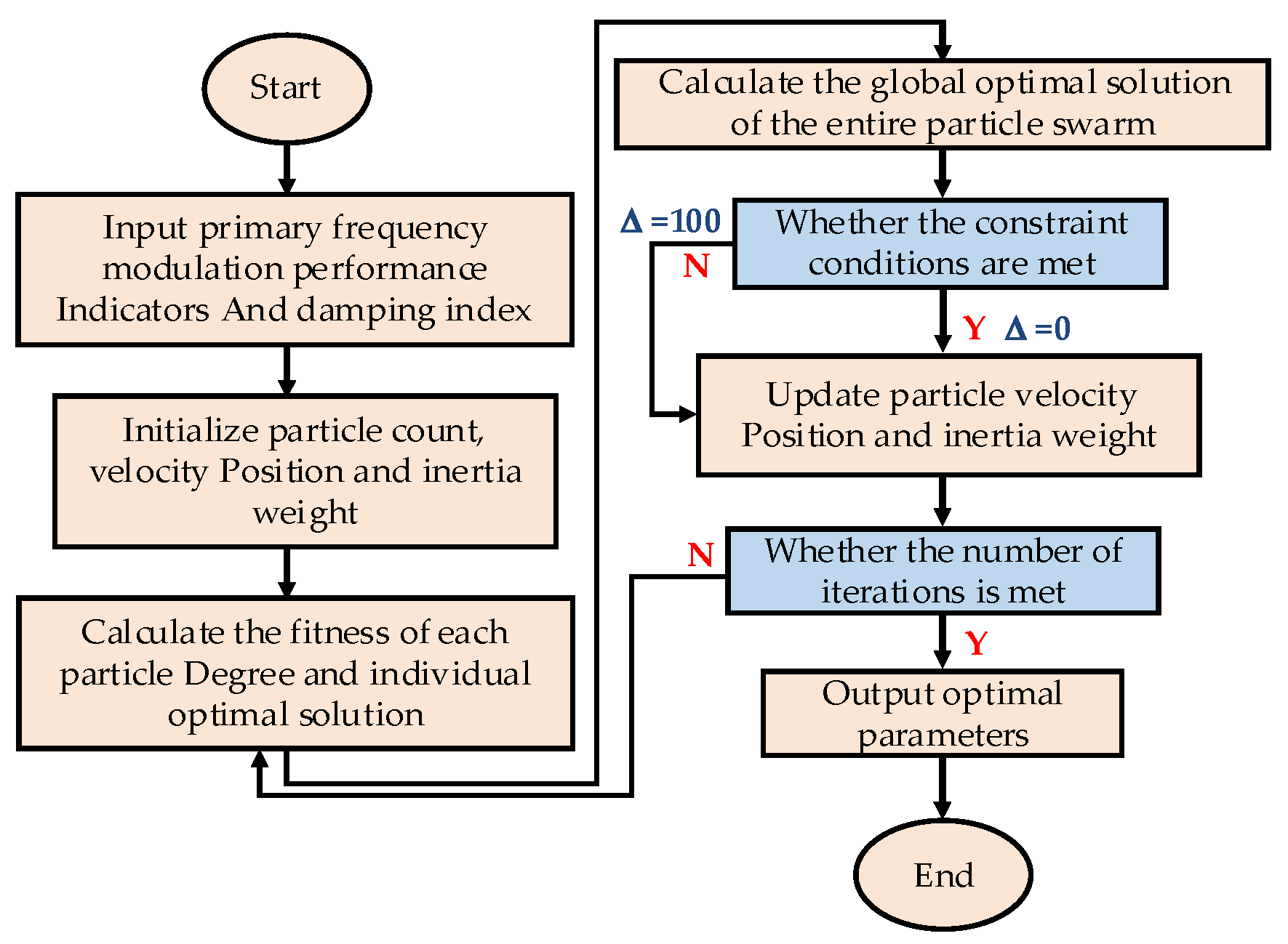
4.3. Comprehensive Control Optimization Model and Solution

The comprehensive, objective function for optimizing main control parameters, including Kd and Kf, considering the damping level and PFR performance. Thus, the comprehensive control optimization model is defined as follows:
{ min A ( K ) = k 3 A 1 ( K ) + k 4 A 2 ( K ) T L 2 s T R 9 s T A 15 s
where k3 and k4 are the weights for the damping torque coefficient index and PFR performance index. TL, TR, and TA are the lag, rise, and adjustment times of PFR, respectively. To ensure fairness in parameter comparison, each parameter must undergo normalization and dimensionless processing.
To solve the proposed comprehensive control model, we adopt the PSO algorithm to obtain optimized control parameters of DFIG. PSO is an evolutionary computation technique that originated from the study of bird flock foraging behavior. It finds wide application in the field of electrical engineering [31]. The PSO simulates the sharing of information among individuals in a bird flock; each particle represents a solution, and it continuously adjusts its velocity and position to search for the optimal solution.
In a population with m particles, each particle having n dimensional variables, the position and flight velocity of the i-th particle in the k-th iteration process are denoted as Xik = [xi,1k,xi,2k, … ,xi,nk] and Vik = [vi,1k,vi,2k, … ,vi,nk], respectively. The individual best position Pik = [pi,1k,pi,2k, … ,pi,nk] and the global best position Gik = [gi,1k,gi,2k, … ,gi,nk] of the population are determined by calculating the fitness value of the objective function for each particle, and the velocity and position of each particle in the next iteration are computed as follows:
{ v i , j k + 1 = σ v i , j k + c 1 r 1 ( p i , j k x i , j k ) + c 2 r 2 ( g i , j k x i , j k ) j = 1 , 2 , , n x i , j k + 1 = x i , j k + v i , j k + 1
where r1 and r2 are random numbers uniformly distributed on the interval [0, 1]; c1 and c2 are learning factors that determine the positional information characteristics of the population, with larger learning factors leading to shorter local optimization times; σ is the inertia weight, which is calculated as follows:
σ = σ max σ max σ min K max k
where Kmax is the maximum number of iterations, σmax is set to 0.9, and σmin is set to 0.4.
The optimization scheme based on the PSO algorithm is illustrated in Figure 9.

5. Simulations and Verification

To validate the effectiveness of the proposed control method, two simulation systems are constructed using PSCAD v50/EMTDC software. Case 1 involves a hydro–wind two-machine islanding system, while case 2 represents an asynchronous hydro–wind system transmitted by HVDC in Southwest China.

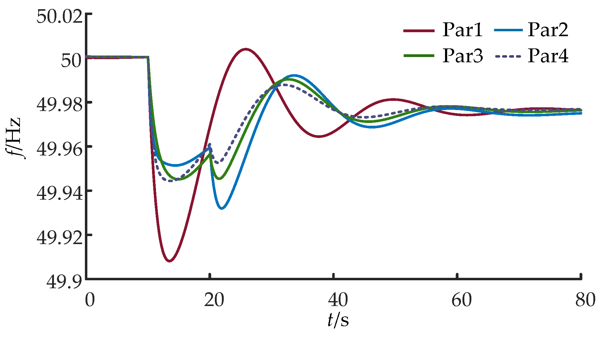
5.1. Case 1: Hydro–Wind Two-Machine Islanding System

In case 1, a hydro–wind two-machine islanding system is presented. Detailed parameters are shown in Table 1.
Based on the analysis above, we select four typical control parameters to simulate the effect of DFIG, which are given below.
Par 1:
No additional control, Kd = 0, Kf = 0.
Par 2:
Only considering damping optimization, Kd = 0, Kf = 50.
Par 3:
Focusing on PFR performance only (Method of Reference [24]), Kd = 35.2, Kf = 25.4.
Par 4:
Comprehensive optimization considering both damping and frequency response, Kd = 15.3, Kf = 30.4.
At 10 s, there is a sudden increase of 10 MW load, and then the system experiences the risk of ULFOs. At 20 s, the DFIG exits frequency regulation. The frequency response curves of the system under different DFIG parameters are shown in Figure 10. To identify the oscillation modes, including damping ratio and oscillation frequency, the TLS-ESPRIT method is applied. When DFIG participates in frequency regulation under different parameters, the corresponding oscillation modes are shown in Table 2. In addition, damping ratios 1 and 2 represent the damping ratio before and after the DFIG exits PFR, respectively.
With Par 1, the DFIG does not participate in system frequency regulation, and it exhibits significant oscillation amplitudes that are difficult to suppress. Par 2 results in higher damping during the DFIG’s involvement in PFR, but the excessive release of rotor kinetic energy after exiting from PFR causes a significant secondary frequency drop, which makes subsequent oscillations challenging to mitigate. Par 3 yields optimal RoCoF and maximum frequency deviation, but with relatively low damping, oscillations persist and are slow to dampen. Par 4 significantly enhances damping compared to Par 3, with damping ratios 1 and 2 increasing by 24.4% and 15.0%, respectively. Meanwhile, it minimizes the impact on PFR performance, leading to a better suppression effect of ULFOs.

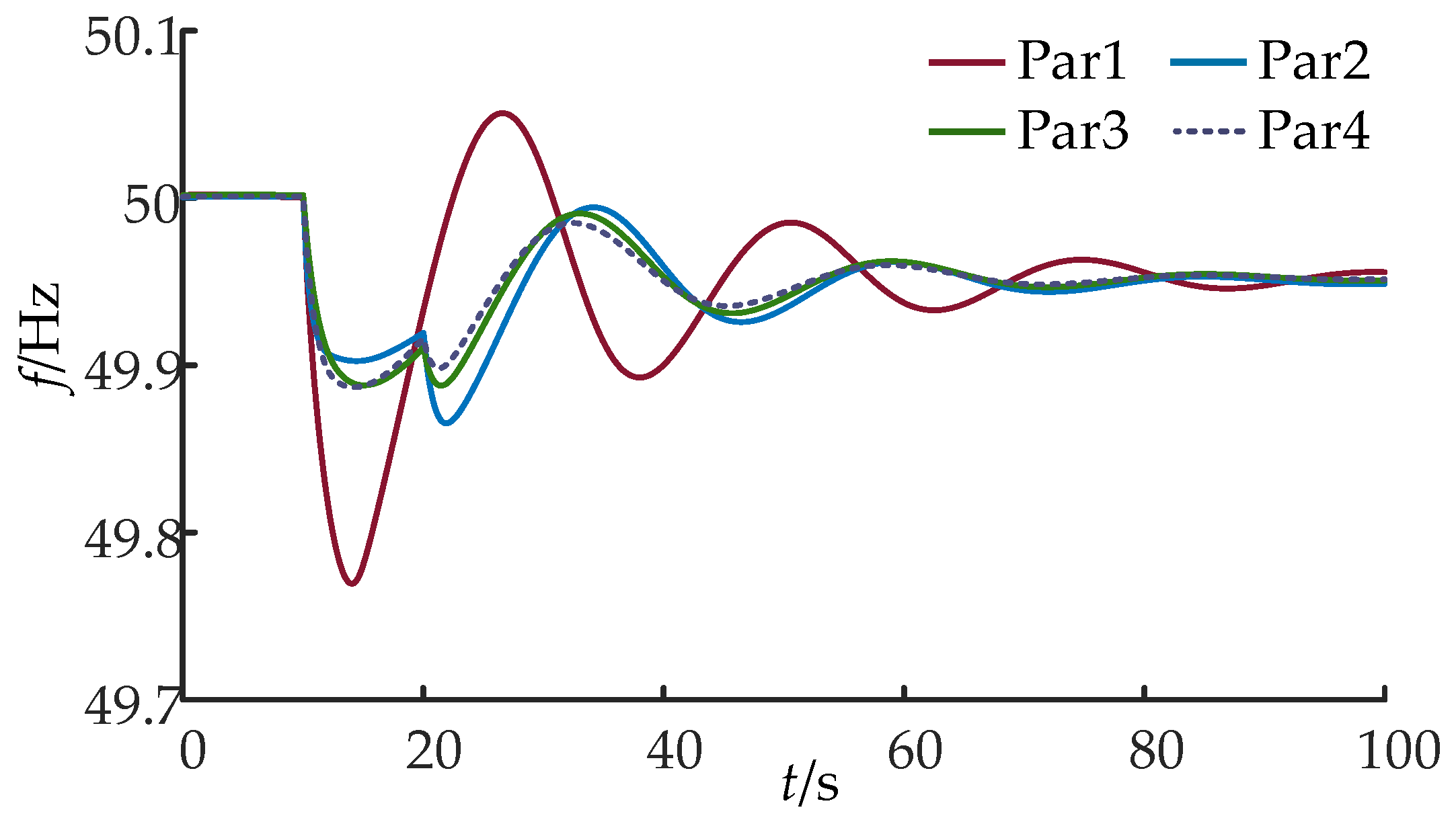
5.2. Case 2: Asynchronous Hydro–Wind System Transmitted by HVDC

In case 2, an asynchronous hydro–wind system transmitted by HVDC is presented as shown in Figure 11. The asynchronous interconnection operation situation is simulated, which is more rational to the occurrence scenario of ULFOs. Detailed parameters are shown in Table 3.
The small disturbance is a sudden increase of 600 MW load at 10 s, and then ULFOs are excited. Figure 12 illustrates the frequency response curves under different DFIG parameters, while Table 4 presents the corresponding damping ratios when DFIG participates in frequency regulation.
In Case 2, four selected parameters are as follows:
Par 1:
No additional control, Kd = 0, Kf = 0.
Par 2:
Consideration of damping optimization only, Kd = 0, Kf = 70.
Par 3:
Focus on PFR performance only (Method of Reference [24]), Kd = 43.2, Kf = 30.6.
Par 4:
Comprehensive optimization of damping and PFR performance, Kd = 20.5, Kf = 36.8.
It is obvious that when the DFIG is not involved in system frequency regulation, the system exhibits large oscillation amplitudes and prolonged oscillation durations. When DFIG participates in system frequency regulation with Par 2, it results in a significant secondary frequency drop. Moreover, Par 3 achieves optimal RoCof and maximum frequency deviation but exhibits relatively low oscillation damping, making it difficult to quickly suppress oscillations. Finally, compared to Par3, optimized Par 4 based on the proposed control method shows that the maximum frequency deviation increases by only 0.001 Hz, and the oscillation damping increases by 24.9% and 15.3%, respectively.
Based on the simulations of both Case 1 and Case 2, it can be further confirmed that the comprehensively optimized control method proposed in this paper significantly enhances the ability to suppress ULFOs while guaranteeing PFR performance. Meanwhile, it retains the frequency regulation of hydropower units.

6. Conclusions

This paper establishes an EUFM of hydro–wind power sending system and investigates the specific impact of WT control parameters on ULFOs and PFR characteristics. Then, a novel optimization objective function considering damping in the ultra-low frequency band and PFR is formulated and solved using the particle swarm optimization (PSO) algorithm. Simulation results verify that the optimized WT parameters can simultaneously address the ULFO problem and guarantee PFR performance. The conclusions can be summarized as follows:
(1)
The negative damping of hydropower units is the fundamental cause of ULFOs, and unlike the LFO issue, ULFO is within the scope of frequency stability.
(2)
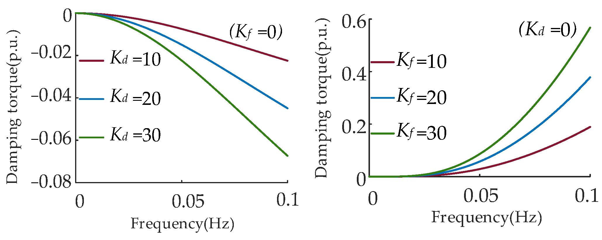
In the ultra-low frequency band of 0–0.1 Hz, the VIC provides a negative damping torque coefficient. In contrast, the droop control provides a positive damping torque coefficient.
(3)
Regarding the influence of DFIG parameters on PFR performance, RoCoF decreases with an increase in Kd; larger Kd and Kf can both reduce the maximum frequency deviation, but the values of Kd and Kf should not be set too large to prevent excessive secondary frequency drop.
(4)
The integration of wind power provides a viable option for ULFO suppression. The objective function is formulated to balance both ULFO suppression and PFR performance. Simulation results verify that the optimized WT parameters improve more than 15% damping ratio while guaranteeing PFR performance.
(5)
In recent years, the control scheme of energy storage systems has been improved [32]. Future research will focus on further investigating wind energy storage systems, considering the strategy of coordinating wind turbines and energy storage to suppress ULFOs.

Author Contributions

Conceptualization, methodology, writing—original draft preparation and resources, R.W.; writing—review and editing, funding acquisition, software and visualization, Q.J.; formal analysis and data curation, B.L.; project administration and investigation, T.L.; validation and supervision, X.Z. All authors have read and agreed to the published version of the manuscript.

Funding

This work was supported by the Sichuan Science and Technology Program (2024NSFSC0865).

Data Availability Statement

The data presented in this study are available on request from the corresponding author. The data are not publicly available due to confidentiality requirements for projects of State Grid.

Acknowledgments

We acknowledge the support given by the State Grid Sichuan Electric Power Research Institute and the College of Electrical Engineering, Sichuan University.

Conflicts of Interest

The authors declare no conflicts of interest.

References

  1. Liu, C.; Zhang, J.; Chen, Y.; Xu, M. Mechanism Analysis and Simulation on Ultra Low Frequency Oscillation of Yunnan Power Grid in Asynchronous Interconnection Mode. South. Power Syst. Technol. 2016, 10, 29–34. [Google Scholar]
  2. Wang, P.; Li, B.; Jiang, Q.; Chen, G.; Han, X.; Dragicevic, T.; Liu, T. The occurrence mechanism and damping method of ultra-low-frequency oscillations. IET Renew. Power Gener. 2021, 15, 1100–1115. [Google Scholar] [CrossRef]
  3. Saarinen, L.; Norrlund, P.; Lundin, U.; Agneholm, E.; Westberg, A. Full-scale test and modelling of the frequency control dynamics of the Nordic power system. In Proceedings of the 2016 IEEE Power and Energy Society General Meeting (PESGM), Boston, MA, USA, 17–21 July 2016. [Google Scholar] [CrossRef]
  4. Pico, H.V.; McCalley, J.D.; Angel, A.; Leon, R.; Castrillon, N.J. Analysis of Very Low Frequency Oscillations in Hydro-Dominant Power Systems Using Multi-Unit Modeling. IEEE Trans. Power Syst. vol. 2012, 27, 1906–1915. [Google Scholar] [CrossRef]
  5. Chen, L.; Min, Y.; Lu, X.; Xu, X.; Li, Y.; Zhang, Y.; Chen, Q. Online emergency control to suppress frequency oscillations based on damping evaluation using dissipation energy flow. Int. J. Electr. Power Energy Syst. 2018, 103, 414–420. [Google Scholar] [CrossRef]
  6. Jiang, Q.; Li, B.; Liu, T. Investigation of hydro-governor parameters’ impact on ULFO. IET Renew. Power Gener. 2019, 13, 3133–3141. [Google Scholar] [CrossRef]
  7. Wang, P.; Jiang, Q.; Li, B.; Liu, T.; Li, X.; Chen, G.; Zeng, X.; Blaabjerg, F. Ultra-low frequency oscillation analysis considering thermal-hydro power proportion. Int. J. Electr. Power Energy Syst. 2023, 148, 108919. [Google Scholar] [CrossRef]
  8. Chen, Y.; Liu, Y.; Tang, Z.; Hou, J.; Zhang, Y.; Mo, W.; Chen, H. Analysis of ultra-low frequency oscillation in yunnan asynchronous sending system. In Proceedings of the 2017 IEEE Power & Energy Society General Meeting, Chicago, IL, USA, 16–20 July 2017; pp. 1–5. [Google Scholar] [CrossRef]
  9. Chen, G.; Tang, F.; Shi, H.; Yu, R.; Wang, G.; Ding, L.; Liu, B.; Lu, X. Optimization strategy of hydrogovernors for eliminating ultralow-frequency oscillations in hydrodominant power systems. IEEE J. Emerg. Sel. Top. Power Electron. 2018, 6, 1086–1094. [Google Scholar] [CrossRef]
  10. Jiang, C.; Zhou, J.; Shi, P.; Li, S.; Huang, W.; Gan, D. Multi-objective robust design of hydraulic turbine governor parameters considering ultra-low frequency oscillation. Power Syst. Autom. 2019, 43, 125–131, 147. [Google Scholar]
  11. Zhang, G.; Zhao, J.; Hu, W.; Cao, D.; Duan, N.; Chen, Z.; Blaabjerg, F. Deep Reinforcement Learning Enabled Bi-Level Robust Parameter Optimization of Hydropower-Dominated Systems for Damping Ultra-Low Frequency Oscillation. J. Mod. Power Syst. Clean Energy 2023, 11, 1770–1783. [Google Scholar] [CrossRef]
  12. Shi, H.; Chen, G.; Ding, L.; Han, X.; Zhang, Y.; Chen, Z.; Liu, C. Optimization of PID parameters for hydraulic turbine governors that balance primary frequency regulation performance and ultra-low frequency oscillation suppression. Power Grid Technol. 2019, 43, 221–226. [Google Scholar]
  13. Jia, Y.; Tan, B.; Zhang, W.; Jiang, D.; Yang, C.; Wen, Y. A Novel Control Strategy for Hydraulic Turbines to Consider Both Primary Frequency Regulation and Ultra-Low Frequency Oscillation Suppression. Energies 2024, 17, 1067. [Google Scholar] [CrossRef]
  14. Vournas, C.D.; Mantzaris, J.C. Application of QSS modeling to stabilizer design for interarea oscillations. IEEE Trans. Power Syst. 2010, 25, 1910–1917. [Google Scholar] [CrossRef]
  15. Zhang, G.; Hu, W.; Cao, D.; Huang, Q.; Yi, J.; Chen, Z.; Blaabjerg, F. Deep reinforcement learning-based approach for proportional resonance power system stabilizer to prevent ultra-low-frequency oscillations. IEEE Trans. Smart Grid. 2020, 11, 5260–5272. [Google Scholar] [CrossRef]
  16. Shi, X.; Ruan, G.; Lu, H.; Chen, H.; Cai, W.; Ron, H.; Chen, G.; Zhao, Y. Analysis of Ultra-Low Frequency Oscillation in Hydro-Dominant Power System and Suppression Strategy by GPSS. IEEE Trans. Ind. Appl. 2023, 59, 2796–2806. [Google Scholar] [CrossRef]
  17. Guo, S.; Zhang, S.; Song, J.; Zhao, Y.; Zhu, W. Tuning approach for power system stabilizer PSS4B using Hybrid PSO. IOP Conf. Ser. Earth Environ. Sci. 2018, 192, 012039. [Google Scholar] [CrossRef]
  18. Haro-Larrode, M.; Santos-Mugica, M.; Etxegarai, A.; Eguia, P. Methodology for Tuning MTDC Supervisory and Frequency-Response Control Systems at Terminal Level under Over-Frequency Events. Energies 2020, 13, 2807. [Google Scholar] [CrossRef]
  19. Xing, C.; Liu, M.; Peng, J.; Wang, Y.; Zhou, Y.; Zheng, Z.; Gao, S.; Liao, J. FLC-Based Ultra-Low-Frequency Oscillation Suppression Scheme for Interconnected Power Grids. Energies 2024, 17, 1300. [Google Scholar] [CrossRef]
  20. Rimorov, D.; Kamwa, I.; Joos, G. Quasi-steady-state approach for analysis of frequency oscillations and damping controller design. IEEE Trans. Power Syst. 2016, 31, 3212–3220. [Google Scholar] [CrossRef]
  21. Zhang, R.; Chen, Y.; Li, Z.; Jiang, T.; Li, X. Two-stage robust operation of electricity-gas-heat integrated multi-energy microgrids considering heterogeneous uncertainties. Appl. Energy. 2024, 371, 123690. [Google Scholar] [CrossRef]
  22. Vidyanandan, K.V.; Senroy, N. Primary frequency regulation by deloaded wind turbines using variable droop. IEEE Trans. Power Syst. 2013, 28, 837–846. [Google Scholar] [CrossRef]
  23. Lee, J.; Muljadi, E.; Srensen, P.; Kang, Y.C. Releasable Kinetic Energy-Based Inertial Control of a DFIG Wind Power Plant. IEEE Trans. Sustain. Energy 2016, 7, 279–288. [Google Scholar] [CrossRef]
  24. Qiao, Y.; Guo, X.; Lu, Z.; Sun, R. Parameter Setting of Auxiliary Frequency Regulation of Wind Turbines Considering Secondary Frequency Drop. Power Grid Technol. 2020, 44, 807–815. [Google Scholar]
  25. Sun, L.; Zhao, X. Modelling and analysis of frequency-responsive wind turbine involved in power system ultra-low frequency oscillation. IEEE Trans. Sustain. Energy 2021, 13, 844–855. [Google Scholar] [CrossRef]
  26. Niasse, M.; Zheng, Q.; Xin, A.; Quan, F.A.F.; Simiyu, P. Mitigating Ultra-Low-Frequency Oscillations in Wind-Penetrated Hydro-dominant Power Grid through Virtual Inertia Emulation Strategy. In Proceedings of the 2020 4th International Conference on Power and Energy Engineering (ICPEE), Xiamen, China, 19–21 November 2020; pp. 130–137. [Google Scholar] [CrossRef]
  27. Xie, R.; KamwaRimorov, I.R.; Moeini, A. Fundamental study of common mode small-signal frequency oscillations in power systems. Int. J. Elect. Power Energy Syst. 2019, 106, 201–209. [Google Scholar] [CrossRef]
  28. Grenier, M.E.; Lefebvre, D.; Van Cutsem, T. Quasi steady-state models for long-term voltage and frequency dynamics simulation. In Proceedings of the 2005 IEEE Russia Power Tech, St. Petersburg, Russia, 27–30 June 2005. [Google Scholar] [CrossRef]
  29. Shu, H.; Wang, G.; Chen, J.; Ma, H.; He, T. Coordinated control of wind-storage combined with primary frequency regulation and variable coefficient based on wind speed and SOC. J. Energy Storage 2024, 87, 111356. [Google Scholar] [CrossRef]
  30. GB/T 40595-2021; Technical Regulations and Testing Guidelines for Primary Frequency Regulation of Grid Connected Power Sources. The State Administration for Market Regulation: Beijing, China, 2021.
  31. AlRashidi, M.R.; El-Hawary, M.E. A survey of particle swarm optimization applications in electric power systems. IEEE Trans. Evol. Comput. 2008, 13, 913–918. [Google Scholar] [CrossRef]
  32. Zheng, X.; Khodayar, M.E.; Wang, J.; Yue, M.; Zhou, A. Distributionally Robust Multistage Dispatch with Discrete Recourse of Energy Storage Systems. IEEE Trans. Power Syst. 2024, 39, 1–4. [Google Scholar] [CrossRef]
Figure 1. Open-loop model of governor and HT.
Electronics 13 03691 g001
Figure 2. The damping coefficient with different parameters. (a) KP = 1~4; (b) KI = 1~4; (c) KD = 0~1.5; (d) TW = 1~2.5 s.
Electronics 13 03691 g002
Figure 3. DFIG control system.
Electronics 13 03691 g003
Figure 4. Diagram of EUFM for hydro–wind sending system.
Electronics 13 03691 g004
Figure 5. Comparison of DFIG damping torque under different parameters.
Electronics 13 03691 g005
Figure 6. Frequency response curve of DFIG.
Electronics 13 03691 g006
Figure 7. Influence on maximum frequency deviation of DFIG parameters.
Electronics 13 03691 g007
Figure 8. Influence on maximum secondary frequency drop deviation of DFIG parameters.
Electronics 13 03691 g008
Figure 9. Optimization algorithm flowchart.
Electronics 13 03691 g009
Figure 10. Frequency curve of the system under different parameters in case 1.
Electronics 13 03691 g010
Figure 11. The asynchronous hydro–wind sending system is transmitted by HVDC.
Electronics 13 03691 g011
Figure 12. Frequency curve of the system under different parameters in case 2.
Electronics 13 03691 g012
Table 1. Simulation parameters of the two-machine islanding system.
Symbol of Islanding SystemValueSymbol of Islanding SystemValue
KP3.6Tw2.4 s
KI1.9Vspeed11 m/s
KD0.5Pwind30.5 MW
TJ10 sPhy69.5 MW
Bp0.04Pload100 MW
Table 2. Case 1: Frequency deviation and damping with different DFIG parameters.
DFIG ParametersΔfmax (Hz)Damping Ratio 1Damping Ratio 2
Par 10.0920.2010.201
Par 20.0640.4340.211
Par 30.0540.2870.220
Par 40.0560.3570.253
Table 3. Simulation parameters of asynchronous hydro–wind system transmitted by HVDC.
Symbol of Sending SystemValueSymbol of Sending SystemValue
KP4Tw2.5 s
KI2Vspeed11 m/s
KD0.5Pdc3000 MW
TJ8 sPwind935 MW
Bp0.04Phy2885 MW
Table 4. Case 2: Frequency deviation and damping with different DFIG parameters.
DFIG ParametersΔfmax (Hz)Damping Ratio 1Damping Ratio 2
Par 10.2310.1750.175
Par 20.1290.3820.177
Par 30.1100.2570.189
Par 40.1110.3210.218
Disclaimer/Publisher’s Note: The statements, opinions and data contained in all publications are solely those of the individual author(s) and contributor(s) and not of MDPI and/or the editor(s). MDPI and/or the editor(s) disclaim responsibility for any injury to people or property resulting from any ideas, methods, instructions or products referred to in the content.

