Article

TWPT: Through-Wall Position Detection and Tracking System Using IR-UWB Radar Utilizing Kalman Filter-Based Clutter Reduction and CLEAN Algorithm

1
College of Computer Science & Engineering, Northwest Normal University, Lanzhou 730070, China
2
Gansu Province Internet of Things Engineering Research Center, Lanzhou 730070, China
*
Author to whom correspondence should be addressed.
Electronics 2024, 13(19), 3792; https://doi.org/10.3390/electronics13193792
Submission received: 1 September 2024 / Revised: 20 September 2024 / Accepted: 23 September 2024 / Published: 24 September 2024
(This article belongs to the Topic Radar Signal and Data Processing with Applications)

Abstract

:
Against the backdrop of rapidly advancing Artificial Intelligence of Things (AIOT) and sensing technologies, there is a growing demand for indoor location-based services (LBSs). This paper proposes a through-the-wall localization and tracking (TWPT) system based on an improved ultra-wideband (IR-UWB) radar to achieve more accurate localization of indoor moving targets. The TWPT system overcomes the limitations of traditional localization methods, such as multipath effects and environmental interference, using the high penetration and high accuracy of IR-UWB radar based on multi-sensor fusion technology. In the study, an improved Kalman filter (KF) algorithm is used for clutter reduction, while the CLEAN algorithm, combined with a compensation mechanism, is utilized to increase the target detection probability. Finally, a three-point localization estimation algorithm based on multi-IR-UWB radar is applied for the precise position and trajectory estimation of the target. Experimental validation indicates the TWPT system achieves a high positioning accuracy of 96.91%, with a root mean square error (RMSE) of 0.082 m and a Maximum Position Error (MPE) of 0.259 m. This study provides a highly accurate and precise solution for indoor TWPT based on IR-UWB radar.

1. Introduction

With the booming application of AIOT [1] and ubiquitous sensing technologies, fields such as autonomous vehicles [2], intelligent factories [3], and intrusion detection have been flourishing in recent years. In all these intelligent applications, the location information of the sensed subject target is crucial for security, emergency and sensing purposes. Recently, the demand for LBS has been growing [4], as the rapid development of new technologies drives the industry’s expansion. LBS technology, which determines the location of a person or an object, is utilized in various smart scenarios, including foot traffic measurement, residential intrusion detection, and personnel rescuing personnel during natural disasters.
Methods for obtaining location information about a target subject are divided into active and passive localization [5]. In active localization, a device or node in a communication network is used to associate the target subject with a mobile station (MS), and the location of the target subject is determined through data transmission between the MS and a base station (BS) [6]. Traditional active localization includes GPS, WSN, cellular networks, and Bluetooth. Passive localization, also known as passive sensing positioning, does not require the target subject to communicate with external devices. Instead, it mainly analyzes reflected signals from the target and uses signal processing techniques to determine its location [7]. Types of passive localization cover wireless ranging radar, laser sensor radar, sonar detection, and more. Each sensing method has its advantages and disadvantages in different application scenarios. For example, in indoor environments or areas with abundant building clutter, GPS is prone to significant errors and drifts when locating or tracking a target. In addition, WSNs and cellular networks often fail to quickly and accurately identify and track targets due to their complex algorithms and cumbersome control mechanisms and protocols. Although sonar and LIDAR can be applied to indoor positioning, they are susceptible to interference and rapid signal attenuation in complex or wall-obscured environments. Visual sensors, such as cameras, are used for indoor positioning but can be susceptible to environmental conditions, such as light and temperature. Therefore, ultra-wideband (UWB) radar has been proposed as an effective indoor localization and tracking technology. The involvement of a wide bandwidth in IR-UWB radar technology means that it has high penetration, accuracy, and resolution [8]. This function enables it to penetrate non-metallic obstacles, such as concrete, partitions and plaster walls, to detect objects outside the walls. In addition, IR-UWB radar features centimeter-level accuracy, low cost, and low power consumption, making it applicable to multitudinous fields. For instance, it can be used to monitor heart rate on a non-contact basis, in addition to detecting abnormal behavior in public places. Indoor localization is an essential issue in the field of computer information, and many relevant studies have been conducted [9,10]. Saab and Nakad proposed a location estimation algorithm using RFID-based low-cost passive tags [11]. An RFID reader module reads signals from low-cost passive tags mounted along an object’s path. They first estimated its location by ignoring the reader angular path loss, and based on this estimation, they proposed a method to implement an iterative procedure to assess the reader angular path loss. Werner et al. proposed a mobile visual indoor localization system based on a distributed architecture [12]. This system uses mobile applications to capture images or videos of the environment. These images or videos are then uploaded to a server and compared with a database to measure the user’s current location. Feldmann et al. experimented with a Bluetooth signal strength-based localization system using a handheld device equipped with a Bluetooth module [13]. The Received Signal Strength Indicator (RSSI) measured by the Bluetooth receiver served as a measurement of how far the transmitter is from the receiver, with triangulation supporting the calculation of the precise position. Dabove et al. proposed and validated a commercial system for indoor localization using Two-Way Time of Flight (TWTF) with UWB technology for precise positioning of people in indoor spaces [14].
In [15], the authors proposed a new approach for the detection and localization of behind-wall moving targets behind a wall using a dual-based UWB radar system. This system is capable of moving target detection, acts as a receiver of UWB pulses emitted by the tags, and calculates their position using the Traditional Time of Arrival (TOA) method. In the article [16], the authors introduced a PLA-JPDA system in which multipath clutter is oppressed with the distance-dependent path loss of radar signals as the basis, but it falls short in accuracy. In a recent study, Bocus et al., based on a multi-site static UWB radar network, conducted an investigation into a passive unsupervised localization and tracking method [17]; the aim of the study is to make indoor target localization more accurate and efficient. Meanwhile, Slimane et al. deeply explored the modified Unscented Kalman Filter (UKF) and proposed an improved scheme for multi-target tracking, which applies to the SαS model under non-line-of-sight (NLOS) conditions [18]. Still, this approach cannot provide accurate localization information of individuals behind the wall.
As mentioned above, IR-UWB radar does not pose privacy concerns related to visual sensors due to its signal characteristics. Its ultra-wideband frequency can measure signals in the area obscured by non-metallic obstacles. However, there are still challenges, such as poor detection and localization accuracy and the inability to effectively perceive the location of a subject behind a wall (in low signal-to-noise ratio (SNR) environments). Given that the approach to analyzing IR-UWB radar signals remains entirely complex, as indicated by many researchers, this research puts forward the utilization of multiple IR-UWB radar devices to sense subjects’ position through walls and, at the same time, track them to generate the trajectory path. The IR-UWB radar transmitter emits a narrow-band pulse, which is reflected upon contact with the subject, and a raw echo signal is generated. This raw echo signal cannot be directly utilized due to environmental influence and multipath effect, i.e., which defy the direct extraction of relevant information, such as the position and trajectory of the subject. For this reason, removing clutter, noise, and other interference signals from the raw echo signal has become the objective for many scholars. However, among many localization algorithms, IR-UWB radar can only adopt the TOA algorithm due to the device itself, i.e., TOA calculates how long a signal takes to travel between the subject and the IR-UWB radar, with such time taken by signal takes being multiplied by how quick light moves to determine the distance. Many scholars have recently investigated IR-UWB radar localization and tracking methods. In [19], the authors proposed using multiple IR-UWB radar devices to create a static radar system, where one device acts as the transmitter and the other two or more devices as receivers. The TOA algorithm forms circles in a plane, and their intersection point indicates the approximate position of the subject. However, due to environmental noise and other clutter signals, these circles may not necessarily intersect accurately, i.e., they fail to determine the accurate location of the subject. To improve accuracy, many scholars have proposed several methods, including spherical interpolation, the least squares method, and a two-segment method combining the Kalman filter (KF) and Taylor series method [20,21] proposed an extended multi-static UWB radar system, which uses elliptical connecting lines to enhance localization accuracy. In [22], a particle filter, combined with IR-UWB radar network nodes, was used to estimate the subject trajectory path, but the method has limitations in accuracy and precision.
The motivation and challenges addressed in this paper are as follows: (1) How to effectively reduce the clutter effects while removing unwanted signals and signal compensation is to improve the target detectability during the processing of raw IR-UWB radar echoes stage. (2) How can the traditional CLEAN detection algorithm be further optimized to overcome the problem of the high false alarm rates of the traditional CLEAN detection algorithm to the subject targets at long distances during the localization process? (3) The problem of inconsistent intersection points when forming intersecting circles in the perceptual model when using multiple IR-UWB radars using the TOA algorithm for subject localization during localization to further improve the detection precision and accuracy.
Based on the above motivations and the challenges addressed, this study puts forward a through-wall position detection and tracking system using multiple IR-UWB radar sensors: TWPT. Compared to the existing literature, the main contributions are as follows: (1) Suppressing clutter signals in IR-UWB radar echoes with the help of the Butterworth filter and smoothing filter and further obtaining pure signals that can be analyzed for the subject’s target position and trajectory with the help of KF-based clutter reduction algorithms and analyzing the data. (2) The CLEAN detection algorithm with compensation is used to overcome the problem of the high false alarm rate of the traditional CLEAN detection algorithm for long-distance targets in the localization process. (3) This paper proposes a multi-view fusion target localization and tracking algorithm. The algorithm estimates the target’s position on the two-dimensional plane based on the distance information extracted from different viewpoints by the three radar devices, further improving detection precision and accuracy.
The remainder of this research is structured as follows: Section 2 discusses the IR-UWB radar signal modeling and presents a schematic diagram of the experimental scenario, along with the preprocessing steps. Section 3 details the algorithm developed for the proposed TWPT. The Section 4 presents experimental data collection, performance evaluation, and analysis of the TWPT algorithm. Finally, in the last section, this research draws a conclusion and outlines directions for future research.

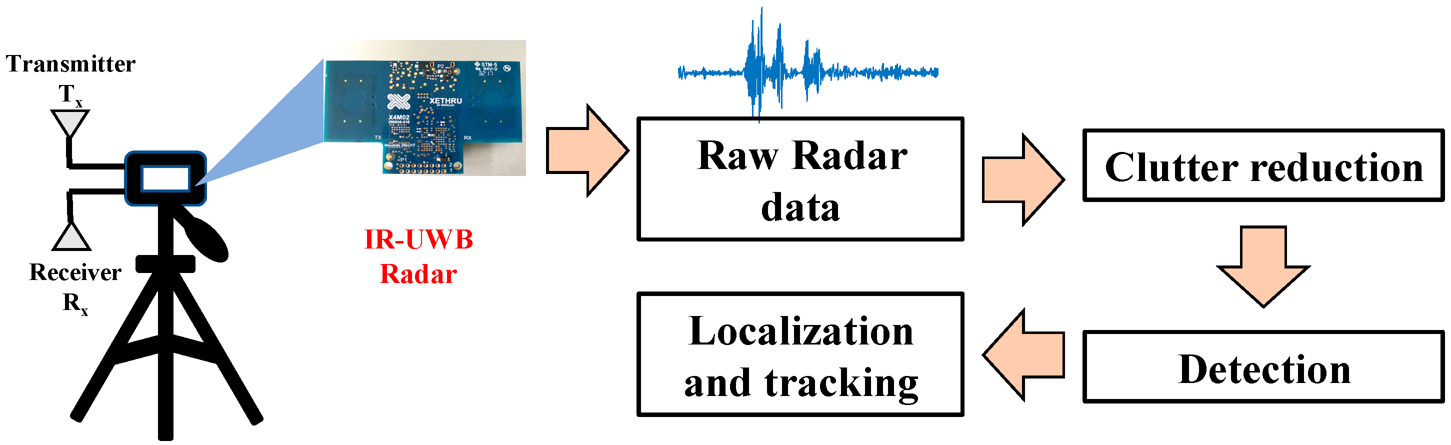
2. IR-UWB Radar Signal Processing

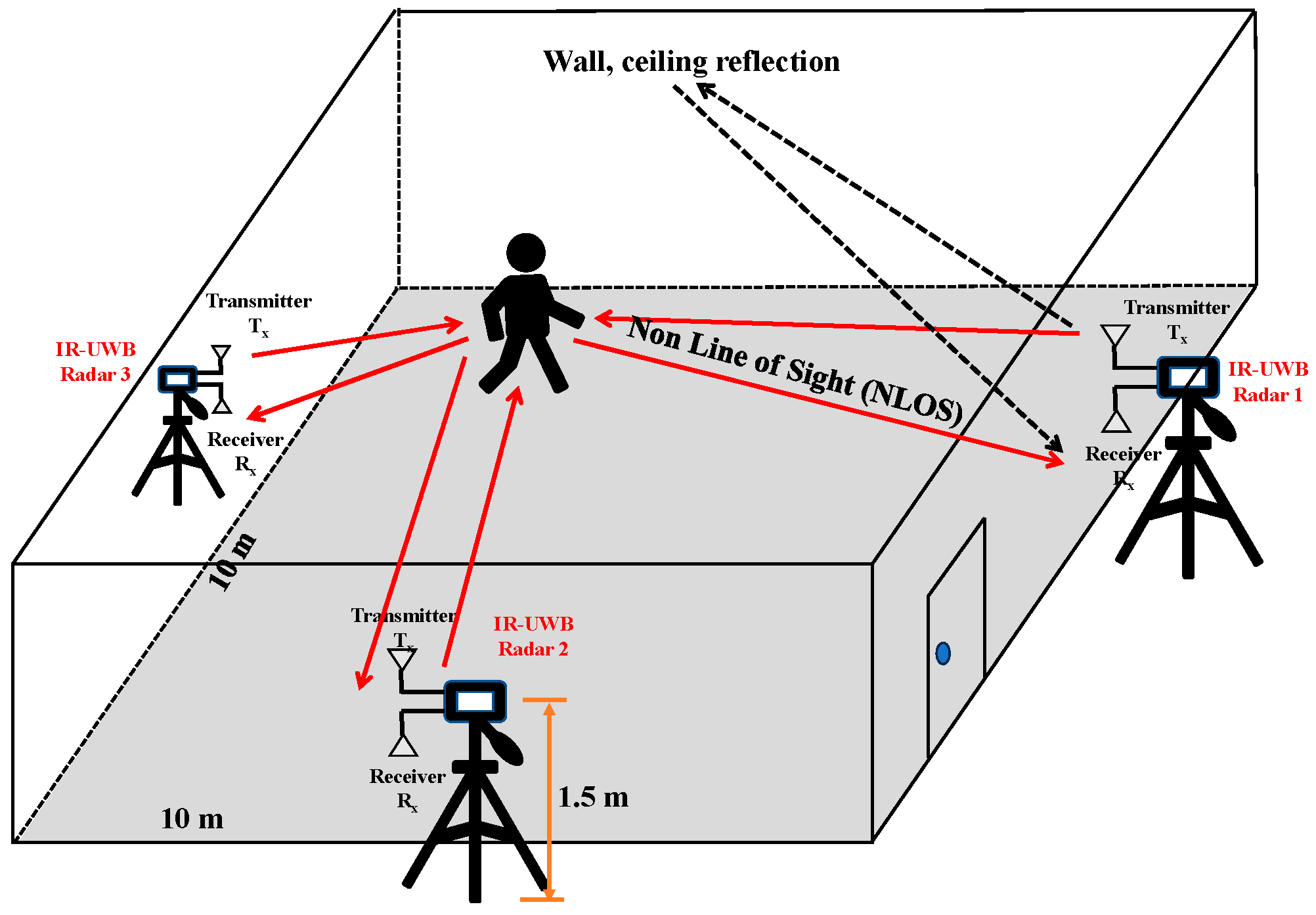
2.1. Experimental Modeling and Signal Preprocessing for IR-UWB Radar

The effectiveness of the TWPT system depends on an experimental environment with limited interference, noise, and multipath effects. This is because the raw echoes received by the IR-UWB radar include much irrelevant information, i.e., clutter signals. Therefore, in this study, accurate position estimation and trajectory tracking are confronted with a challenge related to how useful information could be sourced from these raw echoes laden with interference and clutter. To quantitatively analyze the experimental model and make it simpler, the experiment is conducted within a fixed area of a certain size ( 10   m   × 10   m ). The room is free from any furniture and obstructions, with the IR-UWB radar fixed onto a tripod, with the transmitting end and the receiving end facing upward and downward, respectively. The tripod containing the radar equipment is located outside the house, close to an outer wall, with the radar equipment set 1.5 m above the ground (see Figure 1).
IR-UWB radar transmits and receives pulses with an ultra-wide bandwidth and has a low transmit power. As a result, they are highly penetrating and also significantly lower than common radio signals such as Bluetooth or WIFI, with negligible effects on the human body. However, because the IR-UWB radar pulse is highly similar to noise, the signal processing for IR-UWB radar is typically conducted in the time domain rather than the frequency domain. Let p ( t ) be an underlying IR-UWB radar signal waveform. The transmitted signal s ( t ) can then be expressed as follows:
s ( t ) = k = + p ( t k T s )
where T s denotes the pulse repetition period; in addition, the transmission path in this paper refers to the process in which the transmitter emits a pulse, which then passes through the target before being captured by the receiver. The response of the radio channel of the IR-UWB radar is as follows:
h ( t ) = n = 1 L α n δ ( t τ n )
where L denotes multipath propagations; δ ( t ) denotes the Dirac pulse, a widely utilized generalized function to process signals and is also a unit function. α n represents the amplitude of the n -th propagation path, and τ n is denoted as the propagation delay time of the n -th path [23]. IR-UWB radar signals are transmitted, and the signals received at the receiving end consist of reflected signals (mainly induced by the subject) and additive noise ( t ) , expressed as follows:
r ( t ) = k = + n 1 L α n , k p ( t τ n , k k T s ) + ( t )
After filtering by p ( t ) transmitted by the IR-UWB radar channel, p ( t ) denotes the transmitted signal [24]. At the receiving end, the IR-UWB radar sensor receives the pulse signals, which will be collected or sampled. The data obtained from this sampling are stored as radar scanning frames. n samples constitute each IR-UWB radar scan r [ n ] . Therefore, r [ n ] can be understood as a function of the mapping relationship between the echo signal strength and the number of sample points. The above samples can be used to calculate the propagation time of the IR-UWB radar signal from the signal sampling rate. For further analysis, we classify the samples by building a radargram, i.e., by m consecutive r [ n ] . In this study, the radargram consists of a n × m matrix, where each column in the matrix is an IR-UWB radar scan, denoted as X n × m .
This paper focuses on information about the subject’s position and subsequent movements. The reflected IR-UWB radar echo signals fluctuate with the subject’s movement and other external conditions because the subject tends to be in motion. To facilitate further signal processing and research, the signal received is modeled as follows:
r [ n ] = r t [ n ] + r c [ n ] + ( t )
In Equation (4), the received signal r [ n ] contains the target signal r t [ n ] , the echo reflected from the actual target (containing information such as position) and the static clutter signal r c [ n ] , caused by objects such as walls or ceilings, etc. To detect the subject’s positional information among the many clutter signals, it is necessary to eliminate the unwanted signals, such as clutter or noise, in addition to the r t [ n ] signal. Further analysis with the help of detection algorithms is used to obtain the subject’s location trajectory information. The procedure for which signal is processed follows the methodology suggested in the literature [25]. Refer to Figure 2 for details of the algorithm flowchart.
Usually, the IR-UWB radar signal processing is sequential, where the input of each step is the output from the previous step. First, the acquisition and storage of IR-UWB radar echo signals are facilitated by radargrams. The raw radar echo signals must undergo a series of clutter reduction algorithms for further analysis. This step aims to remove clutter and noise signals that affect the experimental results and positioning accuracy. Many scholars have made efforts in this area; for example, for the indoor short-range detection of subjects, we apply clutter reduction techniques that bear a certain resemblance to the background extraction technique used in visual surveillance algorithms [26] or those used in ground-penetrating radar (GPR) [27]. The Moving Average method represents the most simple and effective clutter suppression algorithm for IR-UWB radar [28]. This method defines clutter as the average of multiple IR-UWB radar scans. However, despite its simplicity, the above algorithm often underperforms. Another algorithm is Exponential Moving Average (EMA) [29], which dynamically updates and estimates the clutter signal based on the previously estimated clutter signal, making it suitable for real-time data processing. Singular Value Decomposition (SVD) [30] is another method mainly applied to through-wall imaging but can also be applied to subject localization and target tracking. Still, the shortcoming is its high system complexity, which requires too much memory and storage resources.
The first step in detecting a subject target is to determine whether the subject is within the detection range. Usually, the practice is based on the relationship between the signal and a certain threshold for comparison. The higher-than-threshold received signal strength (RSS) of the IR-UWB radar indicates the presence of subjects in the area; otherwise, the area is considered unoccupied. Threshold determination can be broadly categorized into two detection algorithms: optimal and suboptimal [31]. The optimal one depends on statistical optimization, primarily the detection rate and false alarm rate under given conditions. This method enables a more quasi-measurement to decide the presence of a target in the subject area. However, the optimal detector involves a more complicated structure, with most scholars reliant on suboptimal detectors for practical applications. To sense targets using infrared IR-UWB radar, matched filters [32] have also been used, but the effectiveness of this method is often limited by the use of templates and IR-UWB radar signal matching degree. In IR-UWB sensing applications, [33] proposed the Constant False Alarm Rate (CFAR) detection method, which can be affected by its inability to accurately differentiate between the target and the noise distributions. Paper [34] proposed the CLEAN algorithm to detect the subject target. This algorithm utilizes the correlation between the received IR-UWB radar signal and a template signal, followed by a comparison with a threshold. However, its disadvantage is that it is significantly affected by the target distance; the further away the target is, the lower the strength of the IR-UWB signal received.
The final step usually involves the application of localization algorithms to determine subject location and trajectory tracking. The process of sensing subject location using UWB radio technology can be facilitated by a series of localization algorithms, such as Angle of Arrival (AoA), Time Difference of Arrival (TDOA), RSS, and Time of Arrival (TOA) [35]. However, in the IR-UWB radar technique, only the TOA obtained from the calculations performed between the radar transmitter and receiver can be used to distance the subject target further [5]. Typically, the target’s TOA is multiplied by the speed of light to obtain the actual distance to the target.
This paper proposes a TWPT system consisting of a signal-processing program for moving target localization and tracking. In the clutter reduction step, an improved Kalman filter-based method for clutter reduction is introduced. The comparison of TWPT and existing methods is demonstrated in Section 4. During detection, a localization and trajectory tracking algorithm is proposed based on the integration of position information from multiple IR-UWB radars. This algorithm is experimentally verified to be both effective and highly accurate.

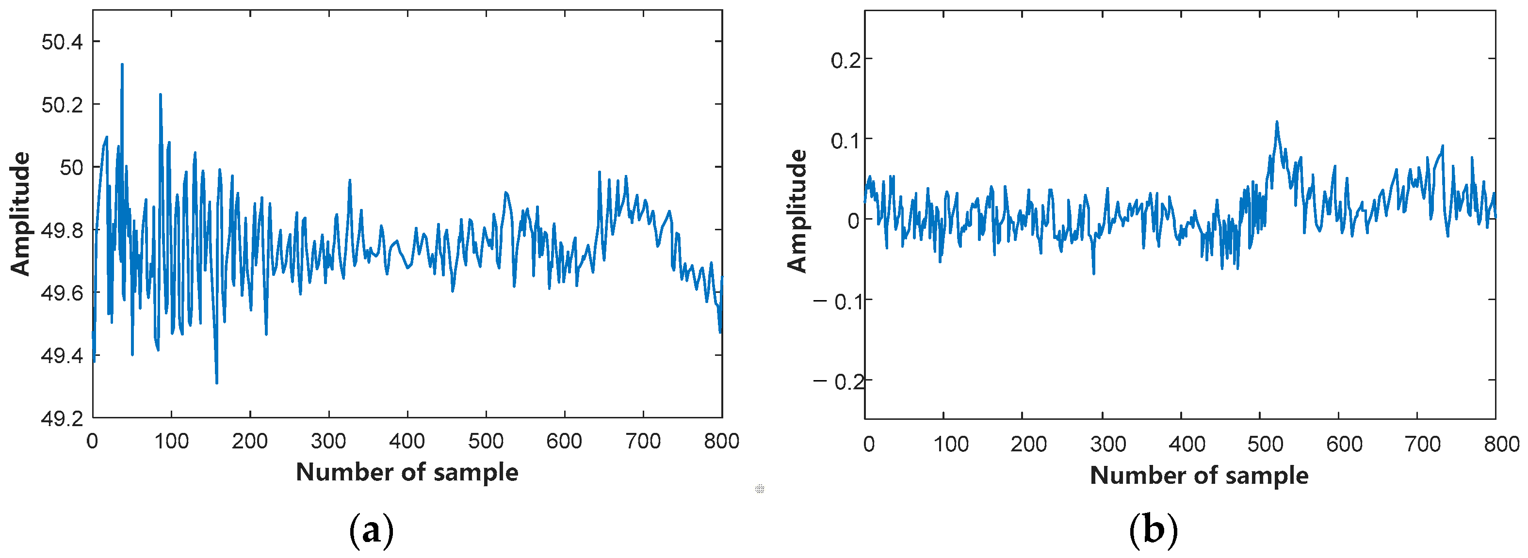
2.2. Clutter Suppression

To further minimize the effect of clutter in the IR-UWB radar echo signal, we filter r [ n ] in Equation (4). Since room temperature, humidity, multipath effect, and dielectric constant all have a significant impact on the echo signal, the signal is further lowered using a Butterworth filter, as shown in the transfer function Equation (5).
H Θ 2 = 1 1 + Θ / Θ c 2 N f
In the above formula, Θ c and N f represent the cutoff frequency and filter order, respectively. Based on the overall algorithm complexity and the filter performance of TWPT, we conducted multiple experiments and finally selected two 5th-order filters, namely N f = 5 . The normalized cutoff frequency is given below.
Θ n c = Θ c f k
where f k denotes the frequency of the fast-time sampling of the IR-UWB radar echo signal. The sampling point n is filtered, which leads to the following equation:
r [ n ] = b 1 W k n + b 2 W k 1 n + + b N b + 1 W m N b n a 2 W m 1 n a N a + 1 W m N a n
where N a and N b are set to 5, i.e., the orders for both the low-pass and high-pass filters are 5. a i and b i are the coefficients of the filters. A smoothing filter capable of oppressing moving noise signals in the IR-UWB radar echo is used, which is expressed as follows:
S k n = 1 μ m = μ k μ k + 1 1 r [ n ]
where k is the value taken from the interval from 1 to M / μ , and . denotes the floor function, which represents downward rounding. Through many experiments, we have determined that averaging seven values in the slow time sampling interval enhances the probability of radar echo detection while effectively suppressing non-stationary noise signal, i.e., μ = 7 .

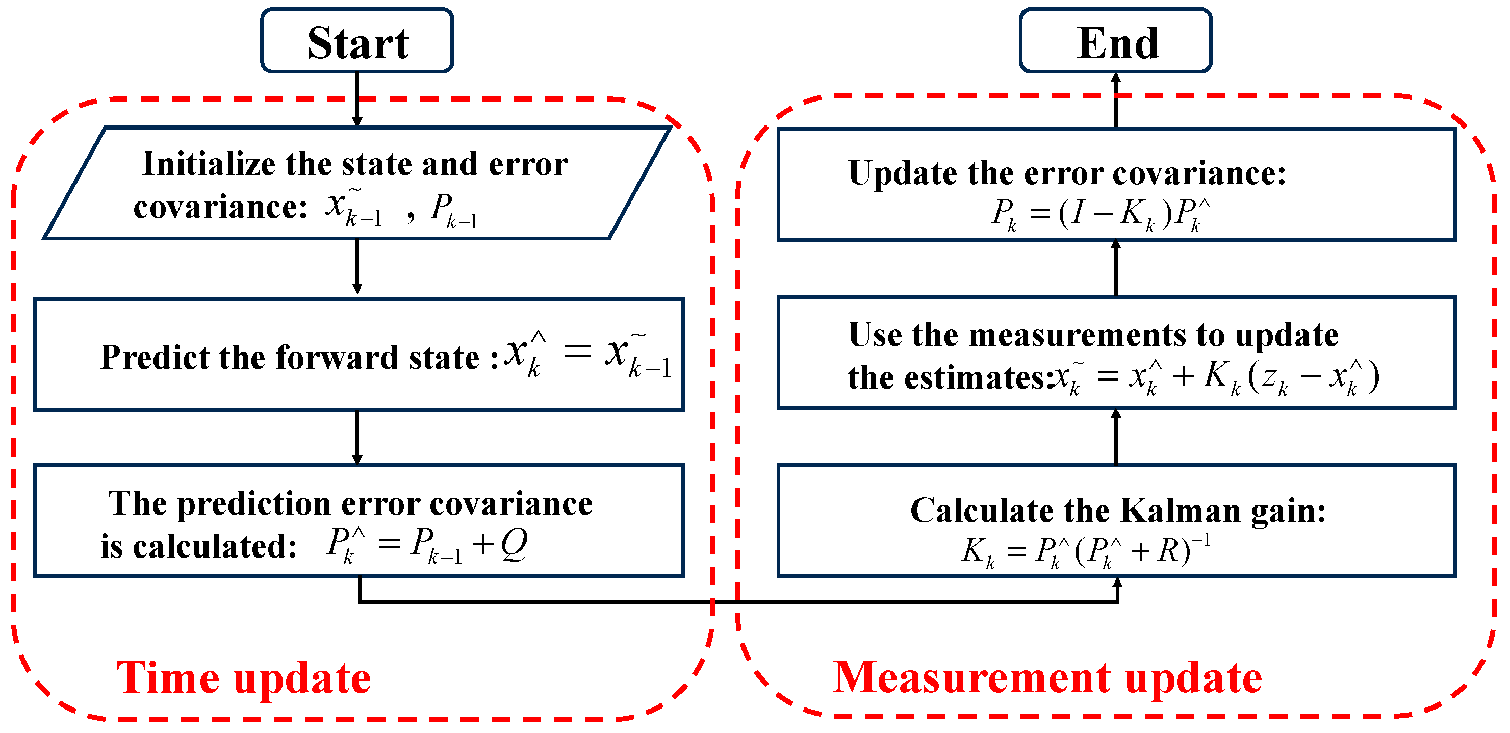
2.3. Clutter Reduction Method Based on Improved Kalman Filter

The Kalman filter (KF) is an optimal estimation algorithm for predicting the state of a linear system based on its equation of state by means of observed data from the inputs and outputs of the system. This method accounts for noise and disturbances present in the observed data. Therefore, it can also be considered a filtering process to achieve an optimal estimation of the system state [36]. The system is assumed discrete, and the state transition equations is assumed to govern the state x k in a dynamic system, as shown in the following equation:
x k = f ( x k 1 , u k 1 , w k 1 )
where u k 1 denotes the input to the IR-UWB radar control, while w k and k denote the process noise and time index, respectively. The true state is hidden on account of the fact that the noise is present in the IR-UWB radar echo. The observed state, often referred to as the measured value, exhibits correlation with the true one through the following equation:
Z k = g ( x k , v k )
where Z k and v k denote the measured value of the state and the measurement noise, respectively. The estimation of the system state is based on the system process and measurement modeling as in Equations (9) and (10). Assuming that w and v are Gaussian additive noises with covariance matrices Q and R , respectively, the state transition Equation (9) and measurement Equation (10) can be rewritten as
x k = A x k 1 + B u k 1 + w k 1 Z k = H x k + v k
To reduce clutter using the KF algorithm, the n samples of the scan constitute the IR-UWB radar clutter, i.e., x k = r C ( k ) . The measurements are the raw radar echo data from the radar scan, i.e., z k = r k . Most clutter consists of static elements, which are assumed to be invariant over time. Thus, we perform the assignment operation on the initial matrix: A = I , B = 0 , H = I .
The algorithm used to reduce clutter and simplify the KF equation is shown in Figure 3.
After the above operations, we will scan and reduce the clutter signal from the original IR-UWB radar echo signal to obtain a pure signal. This pure signal can then be analyzed to determine the target’s position and trajectory. Figure 4 shows the experimental comparison of the original IR-UWB radar echo signal fragment and scan after applying KF-based clutter reduction (i.e., the algorithm of Figure 3).
Usually, the evaluation index for clutter reduction is the average mean root mean square error ( R M S E a ) before and after the observation, which is defined as follows:
R M S E a = 1 M i 1 M 1 N j = 1 N ( r c ( i , j ) r c ( i , j ) ) 2
where M is the number of radar scans, and N is the number of samples. This study uses the same experimental data to quantitatively analyze and compare the clutter abatement method based on the improved Kalman filter proposed in this paper with other methods and calculate the average RMSE for the three filtering algorithms separately. The experimental results are shown in Table 1. From Table 1, the clutter cancelation method based on the improved Kalman filter shows better performance in estimating clutter.

3. TWPT Positioning and Tracking System

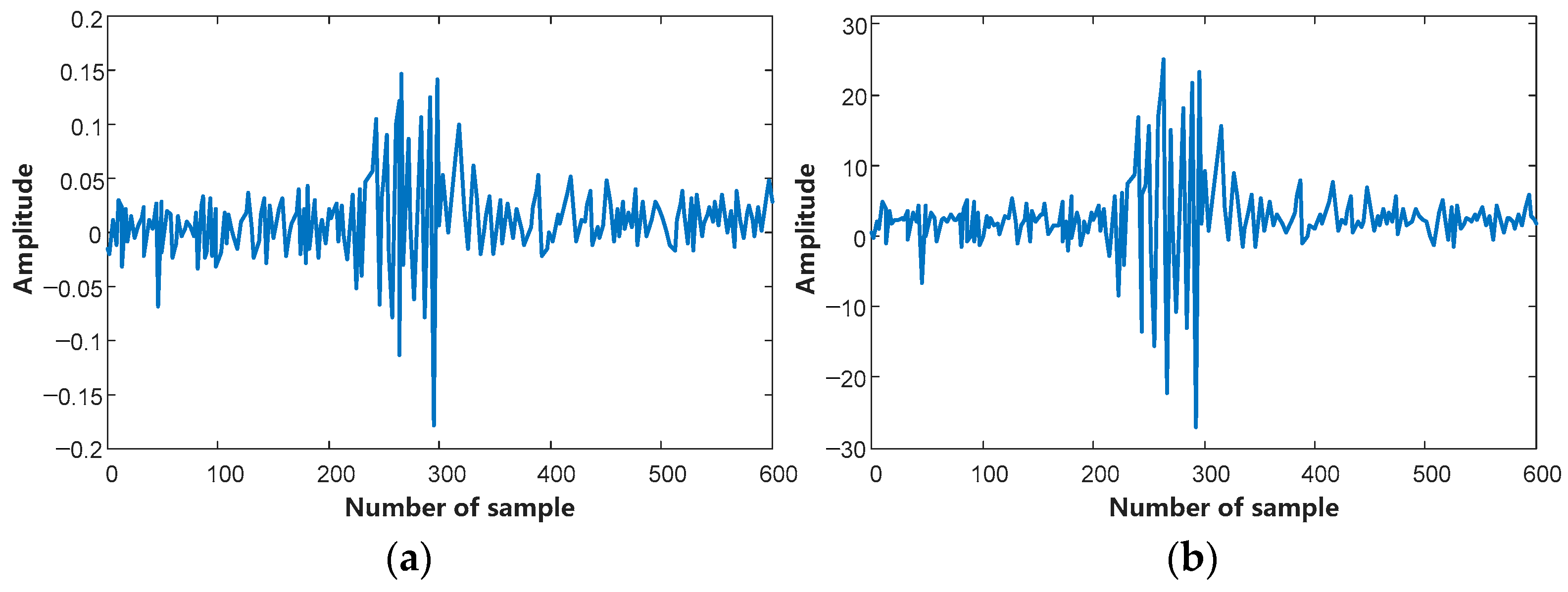
3.1. Improved CLEAN Algorithm for Detection

When sensing the target location, the first step is to determine whether there is a perceiver in the area using the reflected pulses of IR-UWB radar. Usually, the reflected echo signal is compared against a certain threshold. If the reflected signal exceeds this threshold, it indicates a perceived target in the subject area. Conversely, it suggests the absence of a perceived target in the subject area, i.e., an unoccupied situation. Therefore, an improved CLEAN detection algorithm with compensation is proposed. It first compensates for the weak signals reflected from more distant targets. In this subsection, we will first introduce the traditional CLEAN detection method and then present the CLEAN detection algorithm with compensation for the TWPT system.

3.1.1. Traditional CLEAN Detection Algorithm

In the conventional CLEAN detection algorithm [30], the inputs are the IR-UWB radar scan s [ n ] used to eliminate clutter signals, the template signal v [ n ] , and a predefined fixed threshold T , which is obtained by multiplying the average energy value of the IR-UWB radar scan by a scalar. The core idea of the CLEAN detection algorithm is to differentiate the size of the reflected echo signals based on the cross-correlation results and the threshold value and then search for the subject’s reflected echo signals that are correlated with the maximum amplitude and the threshold value. This detection algorithm works by comparing the size of the cross-correlation results with the threshold value and then searching for the reflected echo signals of the subject, i.e., correlate s [ n ] with v [ n ] , and subsequently discriminate the cross-correlation results against the maximum amplitude and the threshold value. Suppose the threshold value v [ n k ] is smaller than the maximum value T . In that case, it has found the target echo signal. The algorithm continues iteratively until the threshold value is higher than the cross-correlation result, at which point all the reflected echo signals are output.

3.1.2. CLEAN Detection Algorithm with Compensation for TWPT Systems

PL is the reduction or attenuation of the power spread density of an electromagnetic signal as it propagates through a wireless channel. It can be expressed as the ratio of the received signal power P r x at the receiving end of the IR-UWB radar to the transmitted signal power P t x at the transmitting end. In the IR-UWB radar sensing system, we process distance and frequency dependence separately, as shown in the following equation:
P L ( f , d ) = P r x / P t x = P L ( f ) P L ( d )
where P L ( f ) f 2 κ and P L ( d ) d n , κ and n denote the frequency attenuation factor and PL index, respectively. As per [37], in an indoor environment, the frequency attenuation factor for line-of-sight (LOS) propagation is roughly 1.7, while for non-line-of-sight (NLOS) propagation, it ranges from 3.5 to 4.1. It has long been established that the amplitude of the received signals is inversely proportional to the radar’s distance from the target. To equalize the strength of the IR-UWB radar echo signals, a compensation operation was performed in this study specifically for the weaker portion of the signal. This is achieved by multiplying the signal by a vector containing a weighting factor, where the weaker part of the signal receives a higher weight. Eventually, the compensated signal can be expressed using the following equation:
s [ n ] = s [ n ] α [ n ]
where s [ n ] is the signal before compensation, and α [ n ] is the vector containing the weighting factors. In the experiment, the vector containing the weighting factor is proportional to the distance. The CLEAN detection algorithm with compensation was then applied to the compensated signal band. Figure 5 shows the result of the compensation for the weak signal of the IR-UWB radar echo: Figure 5a presents the signal observed before compensation, while Figure 5b presents the signal after compensation.
Figure 6 illustrates the error comparison of IR-UWB radar echo signals before and after compensation. The proposed CLEAN detection algorithm with compensation effectively reduces errors in both the X and Y-directions for the IR-UWB radar echo signals, and the errors in both directions are smaller than those in the raw data.

3.2. Localization and Trajectory Tracking Algorithm Based on Position Fusion with Multi-IR-UWB Radar

The CLEAN detection algorithm with compensation in the TWPT system can obtain the variation in the target distance measured by the devices. Then, we need to synthesize the distance information calculated by multiple devices to estimate the position of the human body. We first introduce the traditional three-point localization-based target estimation algorithm in an ideal situation and highlight its limitations in real scenarios. Subsequently, the position estimation algorithm designed in this paper is presented. The technique integrates ranging information from different observation perspectives and accurately determines the target’s trajectory on the two-dimensional plane.

3.2.1. Based on Three-Point Localization Modeling

In two-dimensional space, each radar device P i , i = 1 , , n to the target p 0 each distance between d i determines a circle with p i as the center and d i as the radius. Ideally, the intersection of at least three such circles uniquely determines the position of a target, i.e., the three-point localization method (Figure 7).
When the locations of three devices and the distance from each device to the target are known, and assuming the target is a point mass with no measurement error, the location of the target ( x , y ) satisfies the following equation:
( x x 1 ) 2 + ( y y 1 ) = d 1 2 ( x x 2 ) 2 + ( y y 2 ) = d 2 2 ( x x 3 ) 2 + ( y y 3 ) = d 3 2
where, x i and y i denote the horizontal and vertical coordinates of the i -th device, respectively, and d i denotes the distance from the target to the device. The unique solution of the equation set corresponds to the position of the target.
However, since the human body is an irregular object with thickness, the distance information obtained using the algorithm is actually the distance from each device to the nearest reflection point on the body, which deviates significantly from the real position of the body. In addition, factors such as the limited resolution of the radar distance, errors in device parameters and differences in observation angles among devices all introduce errors, which can make the equation system unsolved, with the failure of the three circles to intersect at a single point.

3.2.2. Three-Point Localization Estimation Algorithm Based on a Multi IR-UWB Radar

To reduce systematic error and achieve high accuracy and robustness in target trajectory estimation, this paper proposes a multi-view fusion target localization and tracking algorithm. This algorithm estimates the position information of the target on a two-dimensional plane based on the distance information extracted by three radar devices from different viewing angles and plots a smooth, accurate trajectory.
Considering the difference in reflection points from different radar viewpoints due to the thickness of the human body, we model the human body as a circle in a two-dimensional plane, with ( x , y ) as the center and r 0 as the radius (set r 0 to 10 cm). Therefore, the true target distance d i is the distance d 0 i extracted by the radar plus the radius, i.e., d i = d 0 i + r 0 . Since the circles centered on the devices, with radii equal to the measured distances, do not have a unique intersection, it is not possible to determine the position of the target directly by solving the system of equations. For this reason, this paper discusses various cases of equation-solving results and designs the following estimation algorithm:
(1) When three circles intersect each other: As shown in Figure 8a, for each pair of intersecting circles, the intersection point closest to the third circle (in terms of the Euclidean distance) is selected as the estimation point. The coordinates of the three points are then averaged to provide the estimated target position.
(2) When one of the three circles intersects with the other two: As shown in Figure 8b, for the two intersecting circles, the intersection point of the two circles closest to the third circle is selected as the estimation point. For the two circles that do not intersect, the estimation point is selected on the line connecting their centers with the same ratio of the radii, i.e., when the first and second circles do not intersect, the coordinates of the estimation point are averaged from the three points to estimate the target’s position.
( x 1 + [ ( x 2 x 1 ) × d 1 ] / ( d 1 + d 2 ) , y 1 + [ ( y 2 y 1 ) × d 1 ] / ( d 1 + d 2 ) )
(3) When only two of the three circles intersect: As shown in Figure 8c, the intersection point of the two intersecting circles closest to the third circle is selected, as well as the closest point to this intersection on the third circle. The coordinates of these two points are averaged to estimate the position of the target.
(4) When none of the three circles intersects: As shown in Figure 8d, for each pair of circles, the point on the line connecting the centers of the circles that are proportional to their radii is selected; for example, the first circle and the second circle are selected based on Equation (16). The coordinates of the three estimated points are then averaged to determine the final estimated target position.
The above method integrates the distance information from three devices to provide real-time estimates of the target position to ensure that the estimation results are free from cumulative error. To further improve tracking accuracy and eliminate outliers, we apply the x and y axes of the target once more (with a window size of 5) to obtain smoother trajectory information. To improve the system in terms of its operation efficiency, the smoothed trajectory information can be downsampled so that the system outputs four trajectory points per second.
Algorithm 1 demonstrates the pseudo-code for the position estimation algorithm based on the fusion of multi-view distance information. The input for the algorithm is the target distance data from three devices, with a dimension of n × 1 . Firstly, the actual target distances are calculated, followed by the utilization of the improved three-point localization method to locate the target, and finally, trajectory filtering is conducted. For each iteration to solve the target position at each moment, the complexity is O ( n ) . The t r a c k function firstly determines the intersection of the circle, centered on the three devices with the measured distance as radii, and then provides the target position at the current moment through an analytical solution, with complexity being constant. The m o v m e a n function applies a fixed window size filter to the change in the target position to output smooth trajectory information, with a complexity of O ( n ) . Therefore, the overall computational complexity of the algorithm is O ( n ) .
Algorithm 1. Localization and Trajectory Tracking Algorithm Based on Position Information Fusion with Multi-IR-UWB Radar
1: Procedure Function targetTracking
2:     d i s t a n c e 1 , d i s t a n c e 2 , d i s t a n c e 3 ;←Target distance envelope for 3 devices
3:     ( x 1 , y 1 ) , ( x 2 , y 2 ) , ( x 3 , y 3 ) ; ←3 device location coordinates
4:     r 0 ←Human modeling radius
5:     W i n d o w ←Trajectory filter sliding window size
6:     d i s t a n c e = [ d i s t a n c e 1 ; d i s t a n c e 2 ; d i s t a n c e 3 ] ;
7:    calculate d i s t a n c e = d i s t a n c e + r 0 ;     Calculate the true target distance
8:       For i t e r = 1 : n
9:         calculate x = t r a c k ( d i s t a n c e ( i t e r , : ) , x 1 , y 1 , x 2 , y 2 , x 3 , y 3 , W i n d o w )
10:          t a r T r a c e ( i t e r ) = x      Solving for target position
11:       EndFor
12:     t a r T r a c e = m o v m e a n ( t a r T r a c e , W i n d o w )      Trajectory filtering
13:    Return t a r T r a c e      Target 2D trajectory
14: End procedure

4. Experimental Results and Analysis

A TWPT system was developed based on a commercial IR-UWB radar to detect the position and motion trajectory of a target subject through a wall. To validate the performance of the TWPT system in terms of localization and tracking, many experiments were conducted in a real experimental scenario. The size of the scenario is 10   m   × 10   m , with the IR-UWB radar transmitter on the device and the receiver beneath. The IR-UWB radar device is fixed on a tripod at a height of 1.5 m. See Figure 1 in Section 2 for the experimental setup. Considering a series of influencing factors, such as the error introduced by different experimenters, the effect of target movement speed on tracking, and the error due to different equipment heights, we adopt the control variable method for quantitative analysis in this study. In addition, comparative experiments with existing non-contact localization algorithms were conducted to validate if the TWPT system was effective.

4.1. Data Collection

This study collected data using three IR-UWB radar sensors developed by Xethru, model X4M02. Figure 9 illustrates a physical diagram of the IR-UWB radar. The specifications of the radar sensors are listed in Table 2. Each radar sensor was fixed on a tripod at a height of 1.5 m. A laptop computer (Lenovo ThinkBook 16+, i5-13500H 32G RAM, 1T) was used for data acquisition, with data collected and transmitted to the radar and Micro Controller Unit (MCU) using a USB interface to connect the laptop to the radar control module, Micro Controller Unit (MCU), and radar. MATLAB software (Version number: R2023b, MathWorks Inc., Natick, MA, USA) was used to read the data from the file in real time and compile it into the received signal spectrum for processing and analysis. The processing window was set to 10 s, with the data updated every second. After preprocessing, which involved the extraction of distance information from individual devices and fusion of distance data from multiple devices, the TWPT system outputted 2D position (trajectory) information at a rate of six times per second. The experimental group consisted of six members, including three males and three females. The age, height, and weight information of the volunteers are shown in Table 3. The IR-UWB radar signals for each subject were acquired separately, and the fixed-point and motion trajectory data were collected.

4.2. Performance Evaluation

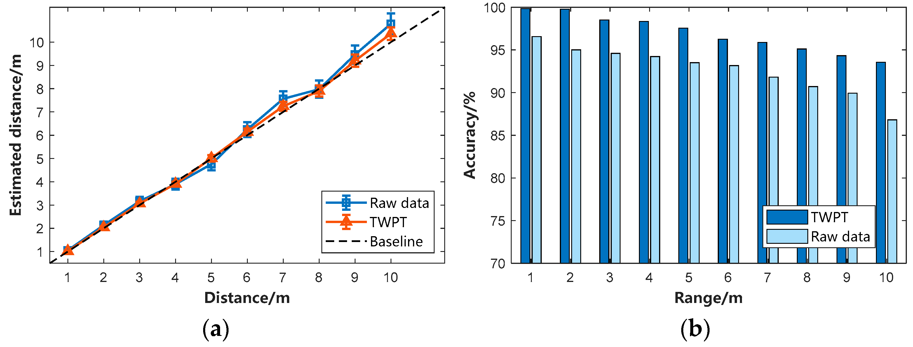
4.2.1. Accuracy of TWPT Positioning System

To investigate the accuracy of the TWPT system at different localization distances, we conducted the following experiments by collecting IR-UWB radar echo data from six subjects at different Y-axis locations (i.e., 1, 2, 3, …… 8, 9, and 10 m) to collect the IR-UWB radar echo data from six subjects along the same horizontal axis (i.e., constant X-axis). Each acquisition requires the subject to remain stationary at the location for 10 s. The raw radar echo data were directly localized for comparison experiments with the proposed TWPT system. See Figure 10 for the experimental results. Figure 10a presents the average estimated distances with error bars, and Figure 10b illustrates the average localization accuracy at a specific point.
From Figure 10a, as the distance gradually increases, the error for both the raw data and the proposed TWPT system also increases, especially when the distance is above 5 m. However, the TWPT system exhibits fewer localization errors than those of the raw data, even as the detection distance is increased to 10 m. As shown in Figure 10a, the folded line remains closer to the baseline. At 10 m, the use of raw data introduces more significant errors, making it difficult to ensure localization accuracy, with the localization accuracy only being 86.81%. However, the proposed TWPT system maintains a high accuracy of 93.56% at 10 m. Therefore, the experiments show that the proposed TWPT can accurately locate the subjects using IR-UWB radar echo signals under the conditions of fixed horizontal distance and changing distance in the vertical direction.
Figure 10b shows the average localization accuracy of six subjects under the conditions of fixed horizontal position and changed vertical position. Figure 10b illustrates that when the IR-UWB radar monitoring range reaches 5 m, the accuracy of the proposed TWPT system drops below 98% for the first time, indicating that the closer the IR-UWB radar is to the target, the higher the detection accuracy, especially within a 5 m range. However, the farther the detection distance is from the system, the lower the system’s effectiveness. This decrease in accuracy is due to the indoor environment, especially in an empty environment; as the detection distance increases, the surrounding walls, floors and ceilings, especially the steel and concrete in the walls, will have a great impact on the IR-UWB radar echoes, thus negatively influencing the accuracy of the TWPT system. The average accuracy of the TWPT system is calculated to be 96.91%, compared to an average accuracy of only 92.64% directly using raw data without the TWPT system. To visualize the effectiveness of the TWPT system’s localization, the average RMSE, as well as the Maximum Position Error (MPE) for the six subjects at different distances, were calculated, respectively, as shown in Table 4. From Table 4, as the distance decreases, the RMSE, as well as the MPE, decrease to different degrees, indicating that the smaller the values of RMSE and MPE, the higher the accuracy, corresponding to more effective detection using IR-UWB radar with the TWPT system. Table 4 shows that the overall RMSE and MPE of the TWPT system are relatively low, with an average of 0.082 m and 0.259 m. Therefore, the proposed TWPT system is much more suitable for application in typical indoor environments and provides a more accurate and convenient LBS for different indoor environments.

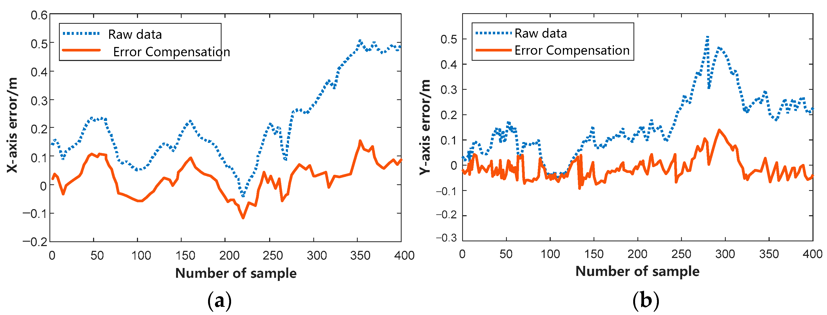
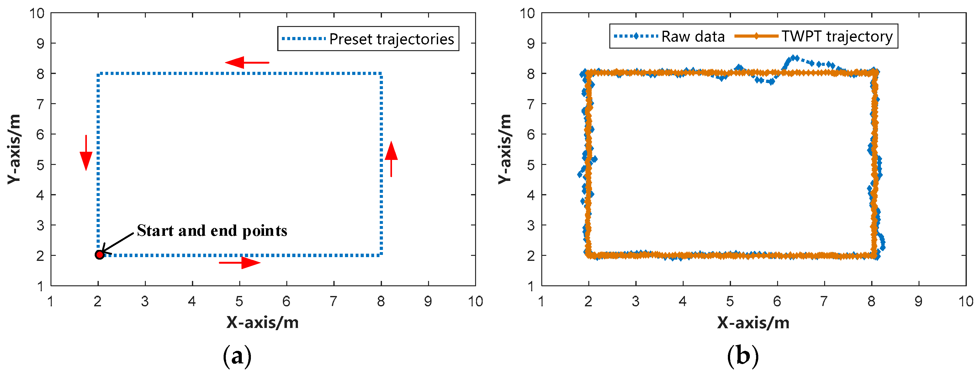
4.2.2. TWPT System Overall Trajectory Error

This section examines the performance of the proposed TWPT system in terms of accuracy in indoor localization and tracking. The indoor open environment was divided into two-dimensional coordinates marked by tapes on the floor. At the same time, six subjects of different genders, ages, and body shapes were invited. The experiment was set up with a common starting point and end position, both (2, 2) walking along a pre-designed trajectory (i.e., (2, 2)→(8, 2)→(8, 8)→(2, 8) with a side length of 6 m, as shown in Figure 11a. To investigate the accuracy and robustness of the TWPT system for tracking, each volunteer completed the trajectory six times. Finally, the Euclidean distance between the system’s estimated location of the target center and the nearest point on the actual trajectory was calculated as the trajectory tracking error of the TWPT system. To visualize the capacity of the TWPT system for localization tracking, the performance of Volunteer 1 on a given trajectory path (averaged over six experiments) is compared to the IR-UWB radar’s raw data path. See Figure 11b for the experimental results.
Figure 11b illustrates the trajectory path of Volunteer 1 at a constant speed of 0.5 m/s along a given route for one lap, using both raw data and the TWPT localization tracking system, respectively. It can be observed that the predetermined trajectory route in Figure 11a is more accurately followed using the proposed TWPT system. Nevertheless, the trajectory tracking based on the IR-UWB radar raw data exhibits significant errors, especially in the (8, 8)→(2, 8) phase, which leads to a considerable localization error at the position of (6, 8), with an error value of as high as 0.6 m. Next, an analysis will be conducted on the influence of the proposed TWPT system on target tracking and localization under different conditions, including varying subjects and speeds.

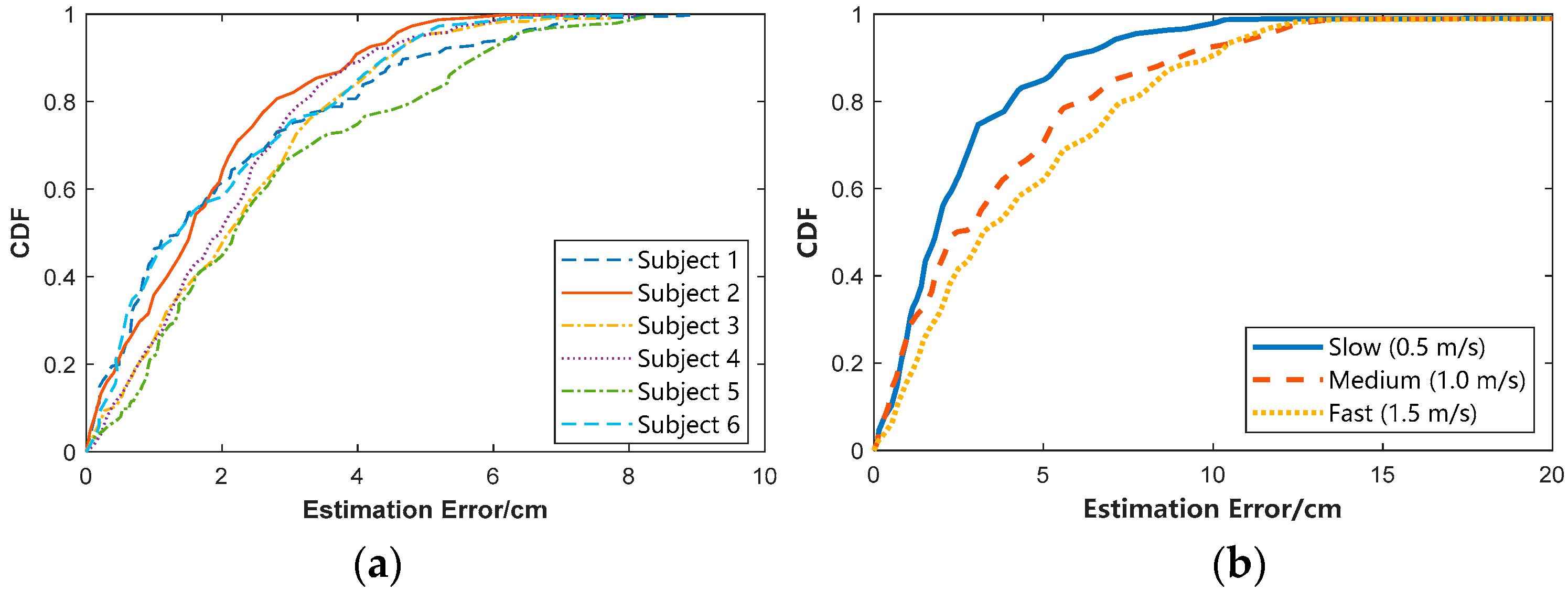
4.2.3. Effects of Subjects and Walking Speed on the TWPT System

As different experimental subjects walk or move with significant differences, differences in their speeds lead to IR-UWB radar signal reflection paths of varying lengths and patterns, which, in turn, lead to different errors in the TWPT system. Therefore, we selected six volunteers for the experiment. The volunteers are both male and female of different ages, heights, and weights. Each volunteer followed a specified route at an average speed of 0.5 m/s, with a sampling duration of 20 s each time, and each sampling was repeated three times. The average Cumulative Distribution Function (CDF) of varying subjects was calculated. See Figure 12a for the experimental results and Figure 12b for the average CDF plots of subject 1. As detected via the TWPT system using IR-UWB radar sensors, subject 1 moves along a fixed trajectory at different speeds: slow (0.5 m/s), medium (1 m/s), and fast (1.5 m/s) speeds.
As shown in Figure 12a, the TWPT system is highly effective, regardless of height, weight, or gender. It achieves the highest accuracy; an average of about 80% of the test data for the six subjects exhibit an error rate of less than 4 cm, while about 90% are less than 6 cm. In this work, we selected subjects 1 and 5 with similar heights for comparative observation. It is clear that the CDF curve for subject 1 is above that of subject 5. This indicates that a shorter distance between the curve and the upper left corner corresponds to more impressive classification performance and more accurate results, suggesting it is closer to the actual subject’s localization and trajectory information. The reason for this is that, under the same conditions, if the weight of the subject is relatively large, the echo signal generated by the IR-UWB radar is more accurately portrayed, with richer information about the subject’s localization and tracking, which improves localization accuracy. Meanwhile, from Figure 12b, the CDF of the estimation error varies when subject 1 moved at three different speeds, where a slow (0.5 m/s) moving speed produces a smaller impact on the TWPT’s system, with an average of about 88% of the test data of subject 1 having an error rate of less than 5 cm. However, a medium speed (1.0 m/s) produces a larger impact on the TWPT system, with only about 75% of the sample points having an estimation error of less than 5 cm. Under fast movement (1.5 m/s) conditions, the positioning accuracy is significantly affected, with only about 57% of the sample points having an error rate of less than 5 cm. This is because rapid speed presents a test to TWPT; the faster the speed, the more significant the algorithm’s processing performance differences, and different moving speeds cause varying perturbations and interference to IR-UWB radar. Specifically, when the subject is moving fast, the limbs will generate a large interference signal, which the IR-UWB radar echo captures as clutter signals that need to be analyzed. In summary, although the different moving speeds of the subjects affect the TWPT system, the difference in the localization and tracking performance is not significant, and relatively high tracking accuracy can still be maintained.

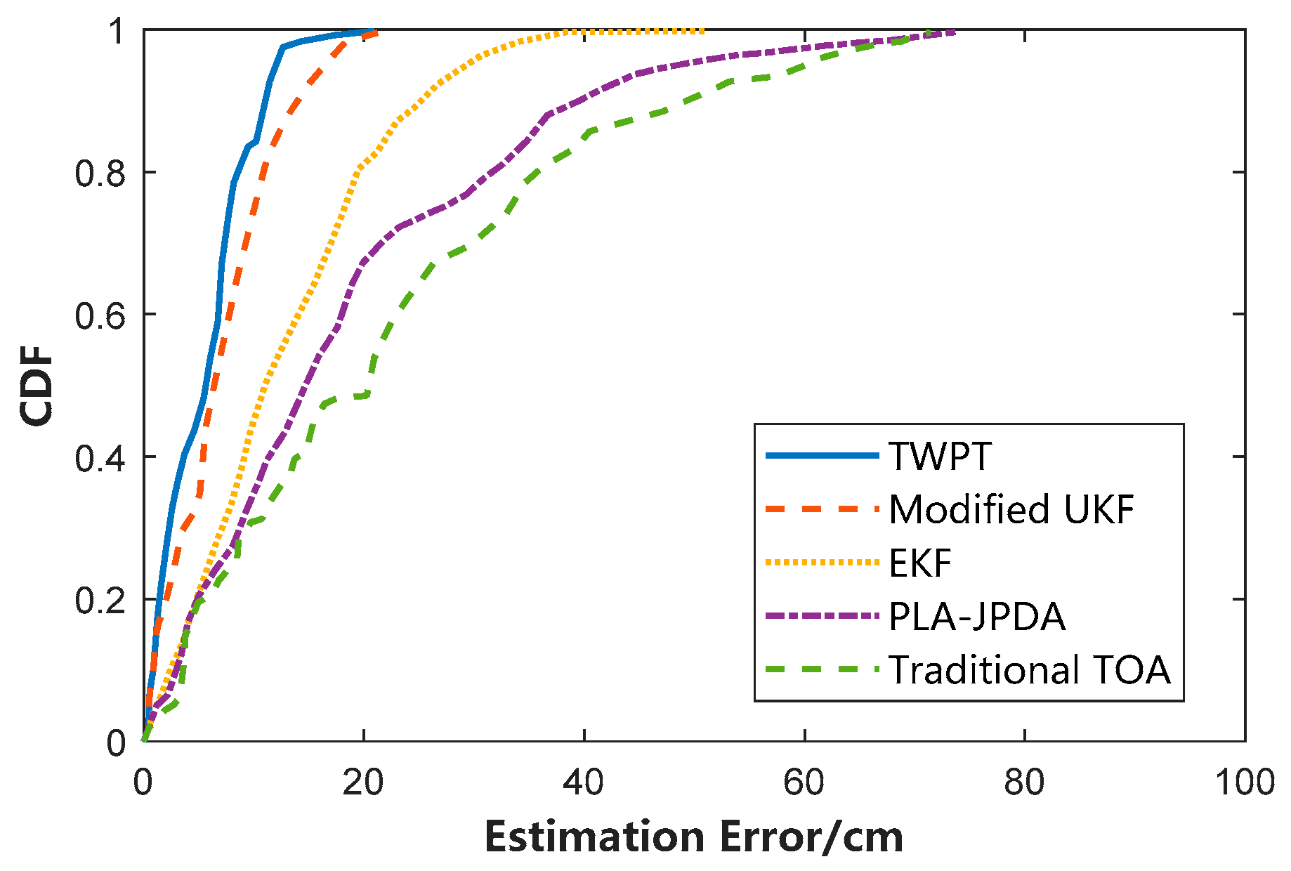
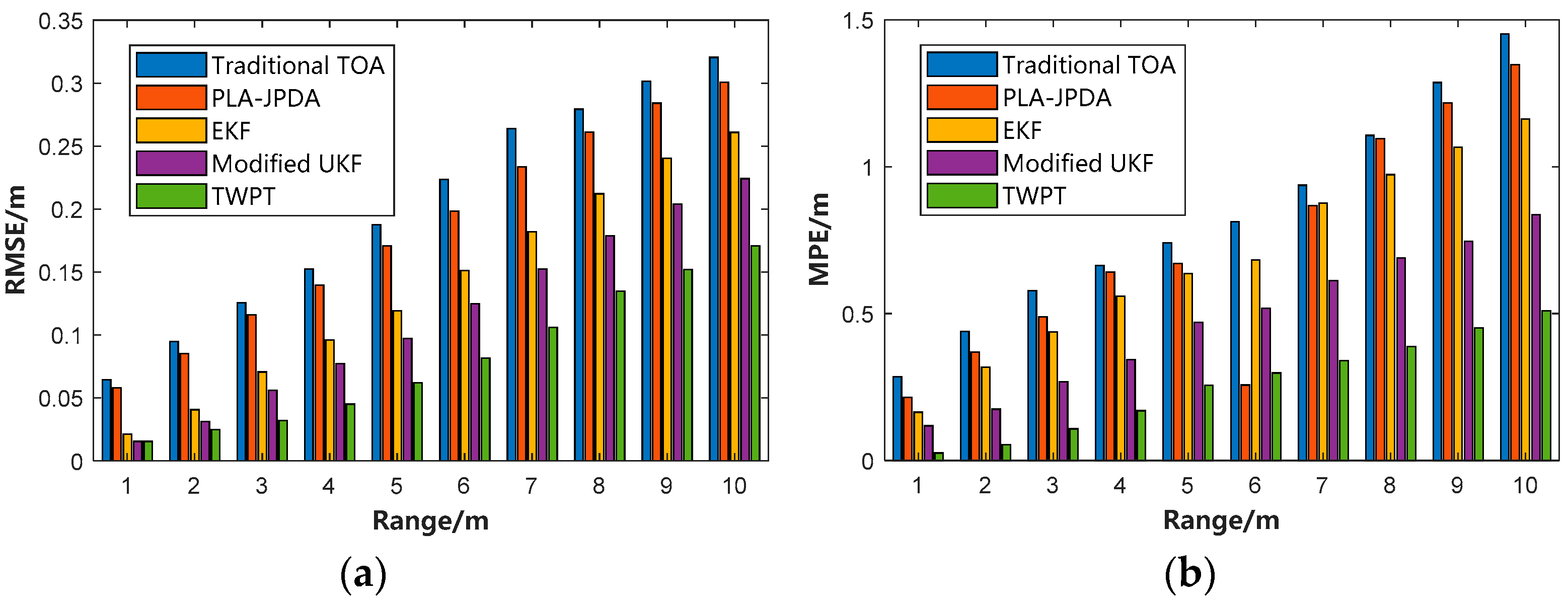
4.2.4. Performance Comparison of Different Localization Tracking Methods

Many researchers have proposed non-contact target tracking algorithms based on UWB radar, and these algorithms have generally exhibited good results in simulation experiments. However, the multipath distribution (walls, ceilings and floors) in real indoor scenarios is much more complex, which places higher requirements on the effectiveness and practicality of these algorithms. A comparative analysis between the proposed TWPT system and several typical and representative indoor localization and tracking methods using UWB radar devices was conducted to further validate its performance. We employed statistical metrics such as CDF, RMSE, and MPE for this comparison. The effectiveness and practicality of the TWPT system were evaluated using the same dataset; the results of the CDF experiments are shown in Figure 13, and those of the RMSE and MPE experiments are shown in Figure 14a and Figure 14b, respectively.
Figure 13 illustrates the cumulative distribution of trajectory tracking errors obtained using five different algorithms using IR-UWB radar echo data obtained from six subjects moving along a prescribed path at a uniform speed (0.5 m/s) in a real empty indoor scene, as shown in Figure 11a. The five algorithms include (1) our proposed TWPT system, (2) the Modified UKF Algorithm, (3) the EKF Algorithm, (4) the PLA-JPDA Algorithm, and the (5) Traditional TOA Algorithm. From Figure 13, the TWPT system outperforms the other methods, with higher accuracy and errors of less than 20 cm. Overall, 93.7% of the sample point errors are less than or equal to 10 cm, while the Traditional TOA algorithm shows the least accuracy, i.e., the CDF curve is near the bottom, and 95.2% of the sample point error is less than or equal to 60 cm. To show more intuitively how effective the proposed TWPT system is, a comparative analysis is conducted among the five algorithms using RMSE and MPE indicators. The experiments were conducted with the same dataset; refer to Figure 14 for the results.
As can be seen from Figure 14, the localization errors of different methods increase to a certain extent with greater detection distances. Still, the TWPT system and the Modified UKF algorithm maintain relatively low errors. Specifically, for a detection range of 10 m, the TWPT system achieves an RMSE of only 0.170 m and an MPE of only 0.509 m. In comparison, the Modified UKF algorithm achieves an RMSE of only 0.224 m and an MPE of only 0.837 m. The superior performance of the TWPT system and the Modified UKF algorithm can be due to their role as tracking filter algorithms. As shown in Figure 14a,b, the TWPT system achieves lower RMSE as well as MPE, regardless of the detection distance.
We also calculated the average accuracy, average RMSE, and average MPE for the five localization tracking algorithms (see Table 5). The average accuracy of the proposed TWPT algorithm, which is 96.91%, is higher than that of the other four comparative algorithms. The average RMSE of 0.082 m and average MPE of 0.259 m for the TWPT system are lower than those of the other methods, indicating that the TWPT system has high accuracy for subject localization tracking and obtains the precise activity trajectory without requirements for a priori knowledge of the target.

5. Conclusions

This paper focuses on the development of an IR-UWB radar-based indoor TWPT system to localize and track indoor moving targets in a more accurate and efficient manner. An analysis of existing localization techniques indicates significant limitations in complex environments, especially in terms of multipath effects and signal attenuation. In response, we employ IR-UWB radar, which has high resolution and penetration capability and can overcome the influence of non-metallic obstacles, such as concrete walls.
In terms of signal processing, this paper utilizes an improved Kalman filter to attenuate clutter in the radar echo signal to improve the SNR. In addition, to further enhance the target detection capability, we introduce the CLEAN algorithm as a signal compensation mechanism to mitigate the effect of PL on long-range targets. The integration of these techniques ensures that the TWPT system performs well in practical applications. We conducted several tests with six volunteers under different motion conditions for system validation, finding that the TWPT system maintains a high localization accuracy in all situations, with more than 98% accuracy, especially at distances up to 5 m. The TWPT system still outperforms the traditional methods, although the error rate increases slightly with the distance, with a positioning accuracy of as high as 93.56% at a distance of 10 m. These results demonstrate the TWPT system’s effectiveness in indoor localization, especially in complex environments. In addition, this paper explores the effects of different subject characteristics and movement speeds on system performance. The experimental results show that a subject’s body size and walking style affect radar signal reflection, which, in turn, affects positioning accuracy. Analysis of data at various speeds reveals that slower movement (0.5 m/s) has less effect on the TWPT system, while fast movement increases positioning errors.
In summary, the TWPT system, with its efficient signal processing and intelligent algorithm design, is applicable to indoor localization and tracking. Future research directions can be carried out in the following areas: (1) We can further optimize the system algorithm to enhance its adaptability in more complex environments. In the future, we can focus on implementing the system in more challenging environments (extreme real-world conditions such as severe interference) and compare the results with controlled experiments. (2) The existing single-dynamic target tracking method can be expanded to include multi-dynamic targets, which could enhance the system and facilitate the exploration of its commercialization potential in practical applications. (3) We will also try to transform the track activity information into subject movement area and movement occurrence frequency analysis, which can be used in the fields of intrusion detection and elderly care.

Author Contributions

J.Z. and X.D. conceived and designed the experiments; J.Z. performed the experiments; J.Z. and X.D. analyzed the data and wrote the paper. J.Z. and Z.H. helped in writing the introduction and the related works and critically revised the paper; Z.H. revised the equations, and critically revised the paper. All authors have read and agreed to the published version of the manuscript.

Funding

This research was funded by the National Natural Science Foundation of China (Grant 62162056), Industrial Support Foundations of Gansu (Grant No. 2021CYZC-06).

Institutional Review Board Statement

Not applicable.

Informed Consent Statement

Informed consent was obtained from all subjects involved in the study. Written informed consent was obtained from the subjects to publish this paper.

Data Availability Statement

Data are contained within the article.

Acknowledgments

The authors would like to thank the reviewers for their thorough reviews and helpful suggestions.

Conflicts of Interest

The authors declare no conflicts of interest.

References

  1. Zhang, J.; Tao, D. Empowering things with intelligence: A survey of the progress, challenges, and opportunities in artificial intelligence of things. IEEE Internet Things J. 2020, 8, 7789–7817. [Google Scholar] [CrossRef]
  2. Feng, S.; Sun, H.; Yan, X.; Zhu, H.; Zou, Z.; Shen, S.; Liu, H.X. Dense reinforcement learning for safety validation of autonomous vehicles. Nature 2023, 615, 620–627. [Google Scholar] [CrossRef] [PubMed]
  3. Hamed, Y.; O’Donnell, G.; Lishchenko, N.; Munina, I. Strain Sensing Technology to Enable Next-Generation Industry and Smart Machines for the Factories of the Future: A Review. IEEE Sens. J. 2023, 23, 25618–25649. [Google Scholar] [CrossRef]
  4. Singh, J.; Tyagi, N.; Singh, S.; Ali, F.; Kwak, D. A Systematic Review of Contemporary Indoor Positioning Systems: Taxonomy, Techniques, and Algorithms. IEEE Internet Things J. 2024, 18, 1. [Google Scholar] [CrossRef]
  5. Nguyen, V.H.; Pyun, J.Y. Location detection and tracking of moving targets by a 2D IR-UWB radar system. Sensors 2015, 15, 6740–6762. [Google Scholar] [CrossRef]
  6. Patwari, N.; Ash, J.N.; Kyperountas, S.; Hero, A.O.; Moses, R.L.; Correal, N.S. Locating the nodes: Cooperative localization in wireless sensor networks. IEEE Signal Process. Mag. 2005, 22, 54–69. [Google Scholar] [CrossRef]
  7. Decarli, N.; Guidi, F.; Dardari, D. A novel joint RFID and radar sensor network for passive localization: Design and performance bounds. IEEE J. Sel. Top. Signal Process. 2013, 8, 80–95. [Google Scholar] [CrossRef]
  8. Fontana, R.J. Recent system applications of short-pulse ultra-wideband (UWB) technology. IEEE Trans. Microw. Theory Tech. 2004, 52, 2087–2104. [Google Scholar] [CrossRef]
  9. Park, C.; Kim, H.; Moon, N. Unauthorized person tracking system in video using CNN-LSTM based location positioning. J. Korea Soc. Comput. Inf. 2021, 26, 77–84. [Google Scholar]
  10. Oh, S.H.; Maeng, J.H. Improvement of location positioning using KNN, Local Map Classification and Bayes Filter for indoor location recognition system. J. Korea Soc. Comput. Inf. 2021, 26, 29–35. [Google Scholar]
  11. Saab, S.S.; Nakad, Z.S. A standalone RFID indoor positioning system using passive tags. IEEE Trans. Ind. Electron. 2010, 58, 1961–1970. [Google Scholar] [CrossRef]
  12. Werner, M.; Kessel, M.; Marouane, C. Indoor positioning using smartphone camera. In Proceedings of the 2011 International Conference on Indoor Positioning and Indoor Navigation, Guimaraes, Portugal, 21–23 September 2011; IEEE: New York, NY, USA, 2011; pp. 1–6. [Google Scholar] [CrossRef]
  13. Feldmann, S.; Kyamakya, K.; Zapater, A.; Lue, Z. An Indoor Bluetooth-Based Positioning System: Concept, Implementation and Experimental Evaluation. In Proceedings of the International Conference on Wireless Networks, New Orleans, LA, USA, 16–20 March 2003; IEEE: New York, NY, USA, 2003; p. 272. [Google Scholar]
  14. Dabove, P.; Di Pietra, V.; Piras, M.; Jabbar, A.A.; Kazim, S.A. Indoor positioning using Ultra-wide band (UWB) technologies: Positioning accuracies and sensors’ performances. In Proceedings of the 2018 IEEE/ION Position, Location and Navigation Symposium (PLANS), Monterey, CA, USA, 23–26 April 2018; IEEE: New York, NY, USA, 2018; pp. 175–184. [Google Scholar]
  15. wei Zhao, X.; Gaugue, A.; Lièbe, C.; Khamlichi, J.; Ménard, M. Through the wall detection and localization of a moving target with a bistatic UWB radar system. In Proceedings of the 7th European Radar Conference, Paris, France, 30 September–1 October 2010; IEEE: New York, NY, USA, 2010; pp. 204–207. [Google Scholar]
  16. Qian, H.; Yang, X.; Zhang, X.; Ding, Y.; Zhang, L. PLA-JPDA for indoor multi-person tracking using IR-UWB radars. In Proceedings of the 2020 IEEE Radar Conference (RadarConf20), Florence, Italy, 21–25 September 2020; IEEE: New York, NY, USA, 2020; pp. 1–6. [Google Scholar]
  17. Bocus, M.J.; Piechocki, R.J. Passive unsupervised localization and tracking using a multi-static UWB radar network. In Proceedings of the 2021 IEEE Global Communications Conference (GLOBECOM), Madrid, Spain, 7–11 December 2021; IEEE: New York, NY, USA, 2021; pp. 1–6. [Google Scholar]
  18. Slimane, Z.; Nouali, I.Y.; Abdelmalek, A. Modified UKF for accurate indoor UWB multi-target tracking in the context of SαS NLOS model. Int. J. Sens. Netw. 2024, 44, 193–202. [Google Scholar] [CrossRef]
  19. Sobhani, B.; Mazzotti, M.; Paolini, E.; Giorgetti, A.; Chiani, M. Multiple target detection and localization in UWB multistatic radars. In Proceedings of the 2014 IEEE International Conference on Ultra-WideBand (ICUWB), Paris, France, 1–3 September 2014; IEEE: New York, NY, USA, 2014; pp. 135–140. [Google Scholar]
  20. Giorgetti, A.; Chiani, M. Time-of-arrival estimation based on information theoretic criteria. IEEE Trans. Signal Process. 2013, 61, 1869–1879. [Google Scholar] [CrossRef]
  21. Kocur, D.; Švecová, M.; Rovňáková, J. Through-the-wall localization of a moving target by two independent ultra wideband (UWB) radar systems. Sensors 2013, 13, 11969–11997. [Google Scholar] [CrossRef] [PubMed]
  22. Sobhani, B.; Paolini, E.; Giorgetti, A.; Mazzotti, M.; Chiani, M. Target tracking for UWB multistatic radar sensor networks. IEEE J. Sel. Top. Signal Process. 2013, 8, 125–136. [Google Scholar] [CrossRef]
  23. Hashemi, H. Impulse response modeling of indoor radio propagation channels. IEEE J. Sel. Areas Commun. 1993, 11, 967–978. [Google Scholar] [CrossRef]
  24. Sahinoglu, Z.; Gezici, S.; Güvenc, I. Ultra-Wideband Positioning Systems: Theoretical Limits, Ranging Algorithms, and Protocols; Cambridge University Press: Cambridge, UK, 2008. [Google Scholar]
  25. Rovnáková, J.; Svecova, M.; Kocur, D.; Nguyen, T.T.; Sachs, J. Signal processing for through wall moving target tracking by M-sequence UWB radar. In Proceedings of the 2008 18th International Conference Radioelektronika, Prague, Czech Republic, 24–25 April 2008; IEEE: New York, NY, USA, 2008; pp. 1–4. [Google Scholar]
  26. Cristani, M.; Farenzena, M.; Bloisi, D.; Murino, V. Background subtraction for automated multisensor surveillance: A comprehensive review. EURASIP J. Adv. Signal Process. 2010, 2010, 1–24. [Google Scholar] [CrossRef]
  27. Abujarad, F.; Jostingmeier, A.; Omar, A.S. Clutter removal for landmine using different signal processing techniques. In Proceedings of the Tenth International Conference on Grounds Penetrating Radar, Delft, The Netherlands, 21–24 June 2004; IEEE: New York, NY, USA, 2004; pp. 679–700. [Google Scholar]
  28. Sabushimike, D.; Na, S.Y.; Kim, J.Y.; Bui, N.N.; Seo, K.S.; Kim, G.G. Low-rank matrix recovery approach for clutter rejection in real-time IR-UWB radar-based moving target detection. Sensors 2016, 16, 1409. [Google Scholar] [CrossRef]
  29. Zetik, R.; Crabbe, S.; Krajnak, J.; Peyerl, P.; Sachs, J.; Thomä, R. Detection and localization of persons behind obstacles using M-sequence through-the-wall radar. In Sensors, and Command, Control, Communications, and Intelligence (C3I) Technologies for Homeland Security and Homeland Defense V, Proceedings of the Defense and Security Symposium 2006, Orlando, FL, USA, 17–21 April 2006; SPIE: St. Bellingham, WA, USA, 2006; Volume 6201, pp. 145–156. [Google Scholar]
  30. Singh, S.; Liang, Q.; Chen, D.; Sheng, L. Sense through wall human detection using UWB radar. EURASIP J. Wirel. Commun. Netw. 2011, 20, 1–11. [Google Scholar] [CrossRef]
  31. Immoreev, I.I. Feature Detection in UWB Radar Signals. In Ultra-Wideband Radar Technology; CRC Press: Boca Raton, FL, USA, 2018; pp. 21–46. [Google Scholar]
  32. Liang, Q.; Zhang, B.; Wu, X. UWB radar for target detection: DCT versus matched filter approaches. In Proceedings of the 2012 IEEE Globecom Workshops, Anaheim, CA, USA, 3–7 December 2012; IEEE: New York, NY, USA, 2012; pp. 1435–1439. [Google Scholar]
  33. Kocur, D.; Gamec, J.; Svecova, M.; Gamcová, M.; Rovnakova, J. Imaging method: An efficient algorithm for moving target tracking by UWB radar. Acta Polytech. Hung. 2010, 7, 5–24. [Google Scholar]
  34. Chang, S.; Sharan, R.; Wolf, M.; Mitsumoto, N.; Burdick, J.W. People tracking with UWB radar using a multiple-hypothesis tracking of clusters (MHTC) method. Int. J. Soc. Robot. 2010, 2, 3–18. [Google Scholar] [CrossRef]
  35. Gezici, S.; Tian, Z.; Giannakis, G.B.; Kobayashi, H.; Molisch, A.F.; Poor, H.V.; Sahinoglu, Z. Localization via ultra-wideband radios: A look at positioning aspects for future sensor networks. IEEE Signal Process. Mag. 2005, 22, 70–84. [Google Scholar] [CrossRef]
  36. Brown, R.G.; Hwang, P.Y. Introduction to Random Signals and Applied Kalman Filtering: With MATLAB Exercises and Solutions; John Wiley & Sons: Hoboken, NJ, USA, 1997. [Google Scholar]
  37. Irahhauten, Z.; Nikookar, H.; Janssen, G.J. An overview of ultra wide band indoor channel measurements and modeling. IEEE Microw. Wirel. Compon. Lett. 2004, 14, 386–388. [Google Scholar] [CrossRef]
Figure 1. Schematic diagram of the experiment.
Electronics 13 03792 g001
Figure 2. Signal processing for locating and tracking the subject target.
Electronics 13 03792 g002
Figure 3. Flowchart of the algorithm used to reduce clutter and simplify the KF equation.
Electronics 13 03792 g003
Figure 4. IR-UWB radar scan: (a) original IR-UWB radar echo signal fragment (b) scan after applying KF-based clutter reduction.
Electronics 13 03792 g004
Figure 5. Compensation of weak signals from IR-UWB radar echoes (a) signal observed before compensation; (b) signal observed after compensation.
Electronics 13 03792 g005
Figure 6. Error comparison of IR-UWB radar echo signals before and after error compensation (a) X-axis; (b) Y-axis.
Electronics 13 03792 g006
Figure 7. Target position estimation method based on three-point localization.
Electronics 13 03792 g007
Figure 8. Four cases of target position estimation by three IR-UWB radars.
Electronics 13 03792 g008
Figure 9. IR-UWB radar diagram.
Electronics 13 03792 g009
Figure 10. Experimental plot of direct localization of raw radar echo data versus TWPT system (a) estimated distance averages and (b) average localization accuracy.
Electronics 13 03792 g010
Figure 11. (a) Predefined trajectory map with start and end points and (b) trajectory routes using raw data and TWPT localization tracking system.
Electronics 13 03792 g011
Figure 12. (a) CDF plot of the effect of different subject targets on tracking and (b) CDF plot of the effect of target movement speed on tracking.
Electronics 13 03792 g012
Figure 13. Tracking CDF error plots for different IR-UWB radar-based localization tracking algorithms.
Electronics 13 03792 g013
Figure 14. Performance of different location-based tracking algorithms at different detection ranges: (a) RMSE and (b) MPE.
Electronics 13 03792 g014
Table 1. Performance comparison of different clutter elimination methods using the same laboratory data sample.
Clutter-Reduction MethodRMSE
Traditional KF algorithm0.1032
Exponential average0.2075
SVD0.1393
TWPT0.0883
Table 2. IR-UWB radar system parameters.
IR-UWB Radar ParametersValue
Detecting range10 m
Bandwidth1.42 GHz
Sampling rate23.3 GHz
Carrier frequency7.3 GHz
Elevation[−70, +70]
Azimuth[−70, +70]
Table 3. Physical information of volunteers.
Volunteer123456
GenderMaleMaleMaleFemaleFemaleFemale
Height(cm)175183169165171167
Weight(kg)808372515761
Table 4. RMSE and MPE for TWPT system localization.
Distance1 m2 m3 m4 m5 m6 m7 m8 m9 m10 mAverage
RMSE(m)0.0150.0240.0320.0440.0620.0810.1060.1340.1520.1700.082
MPE(m)0.0250.0530.1070.1690.2550.2980.3400.3870.4500.5090.259
Table 5. Mean accuracy, RMSE, and MPE for different algorithms.
PapersPublished YearAlgorithmAccuracy (%)RMSE (m)MPE (m)
[15]2010Traditional TOA88.210.2010.829
[16]2020PLA-JPDA91.780.1850.717
[17]2021EKF92.700.1340.687
[18]2024Modified UKF94.360.1160.478
This study TWPT96.910.0820.259
Disclaimer/Publisher’s Note: The statements, opinions and data contained in all publications are solely those of the individual author(s) and contributor(s) and not of MDPI and/or the editor(s). MDPI and/or the editor(s) disclaim responsibility for any injury to people or property resulting from any ideas, methods, instructions or products referred to in the content.

