Hardware Implementation of a 2D Chaotic Map-Based Audio Encryption System Using S-Box


Abstract
1. Introduction
2. The 2D Chaotic Map System Architecture
2.1. The 2D Logistic-Fraction Map (2D-LF)
2.2. The 2D Logistic–Sine (2D-LS) Map
2.3. The 2D Fraction–Sine (2D-FS) Map
2.4. Hardware Implementation of the 2D Maps
- x-y Term Computation Block (See Figure 3a): This block computes the terms and , which are essential to the chaotic maps. It consists of three multipliers, two subtractors, a right shifter, a multiplexer, and a register.
- Angle Calculation Block (See Figure 3b): It calculates the angle for the sine transformation, keeping it within the critical bounds of . If the angle exceeds these bounds, the block adjusts it accordingly.
- Multiplication Block (See Figure 3c): This block adjusts the CORDIC output range to the correct bounds, ensuring that the result is within the range [0, 2].
- Next Iteration Block (See Figure 3b): After determining the angles, this block uses a reconfigurable CORDIC unit to compute the next state values and , which are stored in registers for future iterations.
3. The Proposed Encryption System
| Algorithm 1 Audio Data Encryption Algorithm |
|
4. Results and Discussion
5. Conclusions
Author Contributions
Funding
Data Availability Statement
Conflicts of Interest
References
- Baptista, M. Chaos for communication. Nonlinear Dyn. 2021, 105, 1821–1841. [Google Scholar] [CrossRef]
- Zhang, B.; Liu, L. Chaos-Based Image Encryption: Review, Application, and Challenges. Mathematics 2023, 11, 2585. [Google Scholar] [CrossRef]
- Li, J.; Chen, C.; Rahimi Azghadi, M.; Ghodosi, H.; Pan, L.; Zhang, J. Security and privacy problems in voice assistant applications: A survey. Comput. Secur. 2023, 134, 103448. [Google Scholar] [CrossRef]
- Vaidyanathan, S.; Volos, C. Advances and Applications in Chaotic Systems, 1st ed.; Springer Publishing Company, Incorporated: Berlin/Heidelberg, Germany, 2016. [Google Scholar]
- Pisarchik, A.N.; Zanin, M. Chaotic map cryptography and security. In Encryption: Methods, Software and Security; Nova Science Publishers: Hauppauge, NY, USA, 2010. [Google Scholar]
- Kaur, R.; Gabrijelčič, D.; Klobučar, T. Artificial intelligence for cybersecurity: Literature review and future research directions. Inf. Fusion 2023, 97, 101804. [Google Scholar] [CrossRef]
- Jang-Jaccard, J.; Nepal, S. A survey of emerging threats in cybersecurity. J. Comput. Syst. Sci. 2014, 80, 973–993. [Google Scholar] [CrossRef]
- Yu, F.; Li, L.; Tang, Q.; Cai, S.; Song, Y.; Xu, Q. A Survey on True Random Number Generators Based on Chaos. Discret. Dyn. Nat. Soc. 2019, 2019. [Google Scholar] [CrossRef]
- Ele, B.; Odey, J.; Obono, I. The Impact of Emerging Wireless Network System and Cybersecurity in A Global Community. Trans. Netw. Commun. 2020, 8, 26–42. [Google Scholar] [CrossRef]
- İnce, E.; Karakaya, B.; Türk, M. Designing hardware for a robust high-speed cryptographic key generator based on multiple chaotic systems and its FPGA implementation for real-time video encryption. Multimed. Tools Appl. 2024, 83, 1–34. [Google Scholar] [CrossRef]
- Tanougast, C. Hardware implementation of chaos based cipher: Design of embedded systems for security applications. Stud. Comput. Intell. 2011, 354, 297–330. [Google Scholar] [CrossRef]
- Kumar, K.; Ramkumar, K.; Kaur, A.; Choudhary, S. A Survey on Hardware Implementation of Cryptographic Algorithms Using Field Programmable Gate Array. In Proceedings of the 2020 IEEE 9th International Conference on Communication Systems and Network Technologies (CSNT), Gwalior, India, 10–12 April 2020; pp. 189–194. [Google Scholar] [CrossRef]
- Mohamed, S.M.; Sayed, W.S.; Said, L.A.; Radwan, A.G. Reconfigurable FPGA Realization of Fractional-Order Chaotic Systems. IEEE Access 2021, 9, 89376–89389. [Google Scholar] [CrossRef]
- Mohamed, S.M.; Sayed, W.S.; Radwan, A.G.; Said, L.A. FPGA Implementation of Reconfigurable CORDIC Algorithm and a Memristive Chaotic System with Transcendental Nonlinearities. IEEE Trans. Circuits Syst. I Regul. Pap. 2022, 69, 3165469. [Google Scholar] [CrossRef]
- Volder, J.E. The CORDIC Trigonometric Computing Technique. IRE Trans. Electron. Comput. 1959, EC-8, 330–334. [Google Scholar] [CrossRef]
- Sayed, W.S.; Roshdy, M.; Said, L.A.; Herencsar, N.; Radwan, A.G. CORDIC-Based FPGA Realization of a Spatially Rotating Translational Fractional-Order Multi-Scroll Grid Chaotic System. Fractal Fract. 2022, 6, 432. [Google Scholar] [CrossRef]
- Mohamed, S.M.; Sayed, W.S.; Madian, A.H.; Radwan, A.G.; Said, L.A. An Encryption Application and FPGA Realization of a Fractional Memristive Chaotic System. Electronics 2023, 12, 1219. [Google Scholar] [CrossRef]
- Yeh, J.P. Identifying chaotic systems using a fuzzy model coupled with a linear plant. Chaos Solitons Fractals 2007, 32, 1178–1187. [Google Scholar] [CrossRef]
- Li, C.; Ramachandran, D.; Rajagopal, K.; Jafari, S.; Liu, Y. Predicting Tipping Points in Chaotic Maps with Period-Doubling Bifurcations. Complexity 2021, 2021, 9927607. [Google Scholar] [CrossRef]
- Zhang, Z.; Wu, J.; Chen, Y.; Wang, J.; Xu, J. Distinguish between Stochastic and Chaotic Signals by a Local Structure-Based Entropy. Entropy 2022, 24, 1752. [Google Scholar] [CrossRef]
- Haridas, T.; Upasana, S.D.; Vyshnavi, G.; Krishnan, M.S.; Muni, S.S. Chaos-based audio encryption: Efficacy of 2D and 3D hyperchaotic systems. Franklin Open 2024, 8, 100158. [Google Scholar] [CrossRef]
- Zhang, Y.; Xiang, H.; Zhang, S.; Liu, L. Construction of high-dimensional cyclic symmetric chaotic map with one-dimensional chaotic map and its security application. Multimed. Tools Appl. 2023, 82, 17715–17740. [Google Scholar] [CrossRef]
- Peng, Y.; Sun, K.; Peng, D.; Ai, W. Dynamics of a higher dimensional fractional-order chaotic map. Phys. A Stat. Mech. Its Appl. 2019, 525, 96–107. [Google Scholar] [CrossRef]
- Cao, W.; Cai, H.; Hua, Z. n-Dimensional Chaotic Map with application in secure communication. Chaos Solitons Fractals 2022, 163, 112519. [Google Scholar] [CrossRef]
- Sharobim, B.K.; Yacoub, M.H.; Sayed, W.S.; Radwan, A.G.; Said, L.A. Artificial Neural Network Chaotic PRNG and simple encryption on FPGA. Eng. Appl. Artif. Intell. 2023, 126, 106888. [Google Scholar] [CrossRef]
- Li, Z.; Ravela, S. Neural Networks as Geometric Chaotic Maps. IEEE Trans. Neural Netw. Learn. Syst. 2021, 34, 527–533. [Google Scholar] [CrossRef] [PubMed]
- Sathiyamurthi, P.; Ramakrishnan, S. Speech encryption using hybrid-hyper chaotic system and binary masking technique. Multimed. Tools Appl. 2022, 81, 6331–6349. [Google Scholar] [CrossRef]
- Hameed, A.S. Speech compression and encryption based on discrete wavelet transform and chaotic signals. Multimed. Tools Appl. 2021, 80, 13663–13676. [Google Scholar] [CrossRef]
- Azzaz, M.S.; Kaibou, R.; Madani, B. Co-design based FPGA implementation of an efficient new speech hyperchaotic cryptosystem in the transform domain. Integration 2024, 97, 102197. [Google Scholar] [CrossRef]
- Kaur, G.; Singh, K.; Gill, H.S. Chaos-based joint speech encryption scheme using SHA-1. Multimed. Tools Appl. 2021, 80, 10927–10947. [Google Scholar] [CrossRef]
- Hashemi, S.; Pourmina, M.A.; Mobayen, S.; Alagheband, M.R. Multiuser wireless speech encryption using synchronized chaotic systems. Int. J. Speech Technol. 2021, 24, 651–663. [Google Scholar] [CrossRef]
- Tolba, M.F.; Sayed, W.S.; Radwan, A.G.; Abd-El-Hafiz, S.K.; Soliman, A.M. Hardware Speech Encryption Using a Chaotic Generator, Dynamic Shift and Bit Permutation. In Proceedings of the International Conference on Microelectronics, ICM, Sousse, Tunisia, 16–19 December 2018. [Google Scholar] [CrossRef]
- ElSafty, A.H.; Tolba, M.F.; Said, L.A.; Madian, A.H.; Radwan, A.G. Hardware realization of a secure and enhanced s-box based speech encryption engine. Analog Integr. Circuits Signal Process. 2021, 106, 385–397. [Google Scholar] [CrossRef]
- Zahid, A.; Al-Solami, E.; Ahmad, M. A Novel Modular Approach Based Substitution-Box Design for Image Encryption. IEEE Access 2020, 8, 150326–150340. [Google Scholar] [CrossRef]
- Özkaynak, F.; Çelik, V.; Özer, A.B. A new S-box construction method based on the fractional-order chaotic Chen system. Signal Image Video Process. 2017, 11, 659–664. [Google Scholar] [CrossRef]
- Waheed, A.; Subhan, F.; Suud, M.M.; Alam, M.; Ahmad, S. An analytical review of current S-box design methodologies, performance evaluation criteria, and major challenges. Multimed. Tools Appl. 2023, 82, 29689–29712. [Google Scholar] [CrossRef]
- Yassin, H.M.; Mohamed, A.T.; Abdel-Gawad, A.H.; Tolba, M.F.; Saleh, H.I.; Madian, A.H.; Radwan, A.G. Speech Encryption on FPGA Using a Chaotic Generator and S-Box Table. In Proceedings of the 2019 4th International Conference on Advances in Computational Tools for Engineering Applications, ACTEA 2019, Beirut, Lebanon, 3–5 July 2019. [Google Scholar] [CrossRef]
- Abdullah, S.M.; Abduljaleel, I.Q. Speech Encryption Technique using S - box based on Multi Chaotic Maps. TEM J. 2021, 10, 1429–1434. [Google Scholar] [CrossRef]
- Salvi, D.; Hosler, B.; Bestagini, P.; Stamm, M.C.; Tubaro, S. TIMIT-TTS: A Text-to-Speech Dataset for Multimodal Synthetic Media Detection. IEEE Access 2023, 11, 50851–50866. [Google Scholar] [CrossRef]
- Mohamed, M.A.; Bonny, T.; Sambas, A.; Vaidyanathan, S.; Nassan, W.A.; Zhang, S.; Obaideen, K.; Mamat, M.; Nawawi, M.K.M. A Speech Cryptosystem Using the New Chaotic System with a Capsule-Shaped Equilibrium Curve. Comput. Mater. Contin. 2023, 75, 5987–6006. [Google Scholar] [CrossRef]


| Resources | LF Map | LS Map | FS Map |
|---|---|---|---|
| Lookup Tables (LUTs) | 8663 | 8209 | 9033 |
| Flip Flops (FFs) | 425 | 360 | 539 |
| Digital Signal Processors (DSPs) | 28 | 28 | 24 |
| Operating Frequency (MHz) | 6.024 | 2.376 | 5.208 |
| Power (w) | 0.108 | 0.103 | 0.12 |
| Throughput (Mbps) | 54.216 | 21.384 | 31.248 |
| S-Box 1 | S-Box 2 | ||||||
| 1 | 8 | 12 | 6 | 2 | 11 | 15 | 5 |
| 3 | 4 | 5 | 9 | 0 | 7 | 6 | 10 |
| 0 | 15 | 10 | 7 | 3 | 12 | 9 | 4 |
| 14 | 13 | 11 | 2 | 13 | 14 | 8 | 1 |
| S-Box 3 | S-Box 4 | ||||||
| 5 | 12 | 8 | 2 | 7 | 14 | 10 | 0 |
| 7 | 0 | 1 | 13 | 5 | 2 | 3 | 15 |
| 4 | 11 | 14 | 3 | 6 | 9 | 12 | 1 |
| 10 | 9 | 15 | 6 | 8 | 11 | 13 | 4 |
| Performance Measure | Description and Equation |
|---|---|
| MSE | Measures the difference between the original and encrypted signals. Higher MSE values indicate more robust encryption. Here, : size of the signal or data block; : original signal value; : encrypted signal value. |
| SNR | Measures the noise level in the encrypted signal. A highly negative SNR value indicates high noise compared to the original. Here, : original signal value; : encrypted signal value. |
| Correlation Coefficient | Assesses the linear relationship between the original and encrypted signals. Lower correlation coefficient values indicate better encryption. Here, : original and encrypted signal values; Z: number of signal samples; : covariance between original and encrypted signals. |
| Histogram | Investigates the distribution of signal values. A balanced histogram indicates a more uniform distribution of amplitudes in the encrypted signal. Not applicable. |
| Spectrogram | Visualizes how frequencies change over time, offering insights into the energy distribution across different frequencies in the encrypted signal. Not applicable. |
| Time Waveform | Histogram | Spectrogram | |
|---|---|---|---|
| speech 1 |  |  |  |
| speech 2 | 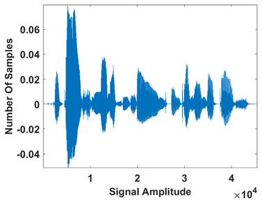 |  |  |
| Speech 1 | Speech 2 | |||
|---|---|---|---|---|
| Encryption | Decryption | Encryption | Decryption | |
| Time Waveform |  | 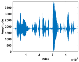 | 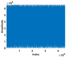 |  |
| Histogram |  | 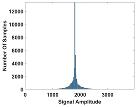 |  |  |
| Spectrogram |  |  |  | 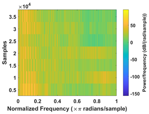 |
| Correlation |  |  |  |  |
| Speech | MSE | Correlation Coefficient | SNR |
|---|---|---|---|
| Speech 1 | 0.003229 | −25.593280 | |
| Speech 2 | 0.002948 | −26.231795 |
| Test | p-Value | Result | Proportion | Result |
|---|---|---|---|---|
| Frequency | 0.066882 | ✓ | 0.938 | ✓ |
| BlockFrequency | 0.122325 | ✓ | 1.000 | ✓ |
| CumulativeSums | 0.051028 | ✓ | 0.938 | ✓ |
| Runs | 0.017912 | ✓ | 0.938 | ✓ |
| LongestRun | 0.000954 | ✓ | 1.000 | ✓ |
| Rank | 0.122325 | ✓ | 0.938 | ✓ |
| FFT | 0.017912 | ✓ | 1.000 | ✓ |
| NonOverlappingTemplate | 0.120018 | ✓ | 0.989 | ✓ |
| OverlappingTemplate | 0.534146 | ✓ | 1.000 | ✓ |
| Universal | 0.213309 | ✓ | 1.000 | ✓ |
| ApproximateEntropy | 0.002043 | ✓ | 1.000 | ✓ |
| RandomExcursions | 0.424511 | ✓ | 1.000 | ✓ |
| RandomExcursionsVariant | 0.317583 | ✓ | 1.000 | ✓ |
| Serial | 0.111904 | ✓ | 1.000 | ✓ |
| LinearComplexity | 0.008879 | ✓ | 1.000 | ✓ |
| Resources | LUTs | FFs | DSPs | Frequency (MHz) | Power (W) | Throughput (Mbps) |
|---|---|---|---|---|---|---|
| Utilization | 14,528 | 440 | 36 | 180 | 0.13 | 2880 |
Disclaimer/Publisher’s Note: The statements, opinions and data contained in all publications are solely those of the individual author(s) and contributor(s) and not of MDPI and/or the editor(s). MDPI and/or the editor(s) disclaim responsibility for any injury to people or property resulting from any ideas, methods, instructions or products referred to in the content. |
© 2024 by the authors. Licensee MDPI, Basel, Switzerland. This article is an open access article distributed under the terms and conditions of the Creative Commons Attribution (CC BY) license (https://creativecommons.org/licenses/by/4.0/).
Share and Cite
Elrefai, H.M.; Sayed, W.S.; Said, L.A. Hardware Implementation of a 2D Chaotic Map-Based Audio Encryption System Using S-Box. Electronics 2024, 13, 4254. https://doi.org/10.3390/electronics13214254
Elrefai HM, Sayed WS, Said LA. Hardware Implementation of a 2D Chaotic Map-Based Audio Encryption System Using S-Box. Electronics. 2024; 13(21):4254. https://doi.org/10.3390/electronics13214254
Chicago/Turabian StyleElrefai, Hisham M., Wafaa S. Sayed, and Lobna A. Said. 2024. "Hardware Implementation of a 2D Chaotic Map-Based Audio Encryption System Using S-Box" Electronics 13, no. 21: 4254. https://doi.org/10.3390/electronics13214254
APA StyleElrefai, H. M., Sayed, W. S., & Said, L. A. (2024). Hardware Implementation of a 2D Chaotic Map-Based Audio Encryption System Using S-Box. Electronics, 13(21), 4254. https://doi.org/10.3390/electronics13214254