Abstract
This article introduces a broadband sub-6 GHz 8 × 8 MIMO (multi-input multi-output) antenna array for 5G (fifth-generation) metal-frame mobile phone applications. The unique advantage of this compact antenna design is its placement in the corners of the mobile phone, allowing for significant PCB board space reduction. The proposed antenna’s 6 dB impedance bandwidth ranged from 3.3 to 6 GHz, covering the n77/78/79 and WiFi-5GHz bands. The main radiating element was an open-slot antenna coupled by a T-shaped structure connected to a 50-Ω transmission line. The size of the single-antenna element was 12.25 mm × 2.5 mm × 7 mm, and these antennas were symmetrical at four corners of the smartphone. A wide slot and neutral line were incorporated to reduce mutual coupling between adjacent antennas. The MIMO antenna array achieved isolation above 12 dB. The peak realized gain ranged from 2 to 5.28 dBi, and the total efficiency spanned 37% to 71%. The ECC (envelope correlation coefficient) was less than 0.34, and the CC (channel capacity) ranged from 33 and 41 bps/Hz.
1. Introduction
Consumer electronic devices are constantly evolving, and people demand high-performance and attractive designs in these products. Smartphones with metal frames or all-metal backs enhance durability and texture, but metal parts can interfere with wireless communication signals and complicate antenna design. To address this, antennas in smartphones with metal frames often use slot antennas or clearance ground planes to mitigate the metal’s impact on signal reception [1,2,3,4,5,6,7,8,9,10,11,12]. Users seek appealing designs and high performance, such as fast data transmission rates, in their mobile phones.
Fifth-generation mobile communication is attractive due to the high data transmission rate and low latency. Two NR (new radio) frequency bands, FR1 (450–6000 MHz), called the sub-6 GHz band and FR2 (24.25–52.6 GHz) in the millimeter wave band, were defined by 3GPP [13]. Because the millimeter waveband has a broad frequency bandwidth, it can easily contain a large amount of information and obtain a high data transmission rate. However, the high frequency brings shortages so that it is more difficult for signals to penetrate objects, and the transmission distance becomes shorter. As a result, the sub-6 GHz frequency band is predominantly used so far due to its more mature technology. MIMO technology is adopted to improve the data transmission rate. Because of MIMO technology, there are many antennas in one mobile phone, and mutual coupling problems should be considered. Because high mutual coupling results in a low data transmission rate, improving the isolation of adjacent antennas is vital in the design of a MIMO antenna system.
Reducing mutual coupling between adjacent antennas is crucial, and many approaches to improve isolation have been studied, including polarization division, radiation pattern division, space division, and the addition of decoupling components or techniques [6,7,8,9,10,14,15,16,17,18,19,20,21]. The polarization division method excites antennas in the orthogonally polarized modes or waves, achieving good isolation over 10 dB [6,14]. Adopting radiation pattern division to avoid maximum radiation directions can achieve isolation levels exceeding 20 dB [15]. The approach needs a pure polarization of the radiation field to obtain high isolation. Space division is another method for improving isolation, and it involves properly arranging the direction of the antennas and increasing the distance between antennas [16,17]. The shortage of this approach is that a large space is needed. Additionally, adding decoupling components or techniques, such as an inductor, a capacitor, open slots, stubs, resonators, shorting strips, or a neutral line, between the antennas can successfully reduce coupling [7,8,9,10,18,19,20,21]. The inductor, which is one of the decoupling components, can lead the currents of the two antennas to cancel each other out [18], and a strip makes the two antennas operate in two different modes, the common mode and differential mode, to obtain good isolation [7]. Adding extra components will bring additional costs. Also, adding an unground resonator behind the slot antennas improves isolation [8]. Inserting a ground stub, an H- or I-shaped slot, between antennas can prevent ground current coupling [9,10,19]. Introducing shorted strips achieves not only a decoupling function, but also main radiators [20]. The approach needs extra space for a resonator. Loading a neutral line in two antennas results in an isolation lever over 17 dB [21]. The shortcoming is that those two antennas should be adjacent because the neutral line connects those two antennas together.
Aside from the isolation, a broad operating bandwidth is another requirement for a 5G MIMO antenna array because the operating bandwidth of a 5G antenna should cover n77/78/79 channels. The paper [11] proposed a hybrid inverted-F and slot antenna with a tuning stub as a capacitor and a meandered line serving as an impedance transformer, achieving a broad frequency band of 3.3–7.1 GHz. In this paper, extra space was needed. In [12], a slot antenna with tuning stubs and tuning strips employed for impedance matching could achieve a 3.27–5.92 GHz broadband design. In [22], a T-shaped slot and feeding line were used to achieve a broad frequency band coverage of LTE Bands 42/43/46.
This article proposes a sub-6 GHz MIMO antenna array for the 5G mobile phone intended for metal-frame and back applications. This MIMO antenna array enhanced isolation between antennas without using any passive components. This broadband antenna element was created by combining two strategically placed slots in the corners of the mobile phone. This unique design offers a significant advantage by optimizing the use of internal space on the PCB board. Notably, this antenna exhibited a broad operating bandwidth, with a 6 dB impedance bandwidth from 2.8 to 6 GHz. This wide bandwidth covered the NR n77/78/79 and WiFi-5GHz bands. In this article, all simulated results were obtained by Ansys HFSS.
2. Antenna Design and Simulated Results
This section introduces the geometry of the broadband 8 × 8 MIMO antenna array designed for metal-frame 5G mobile phone applications at first, and then discusses the resonance mechanism of the proposed antenna in detail.
2.1. Antenna Structure and Principle
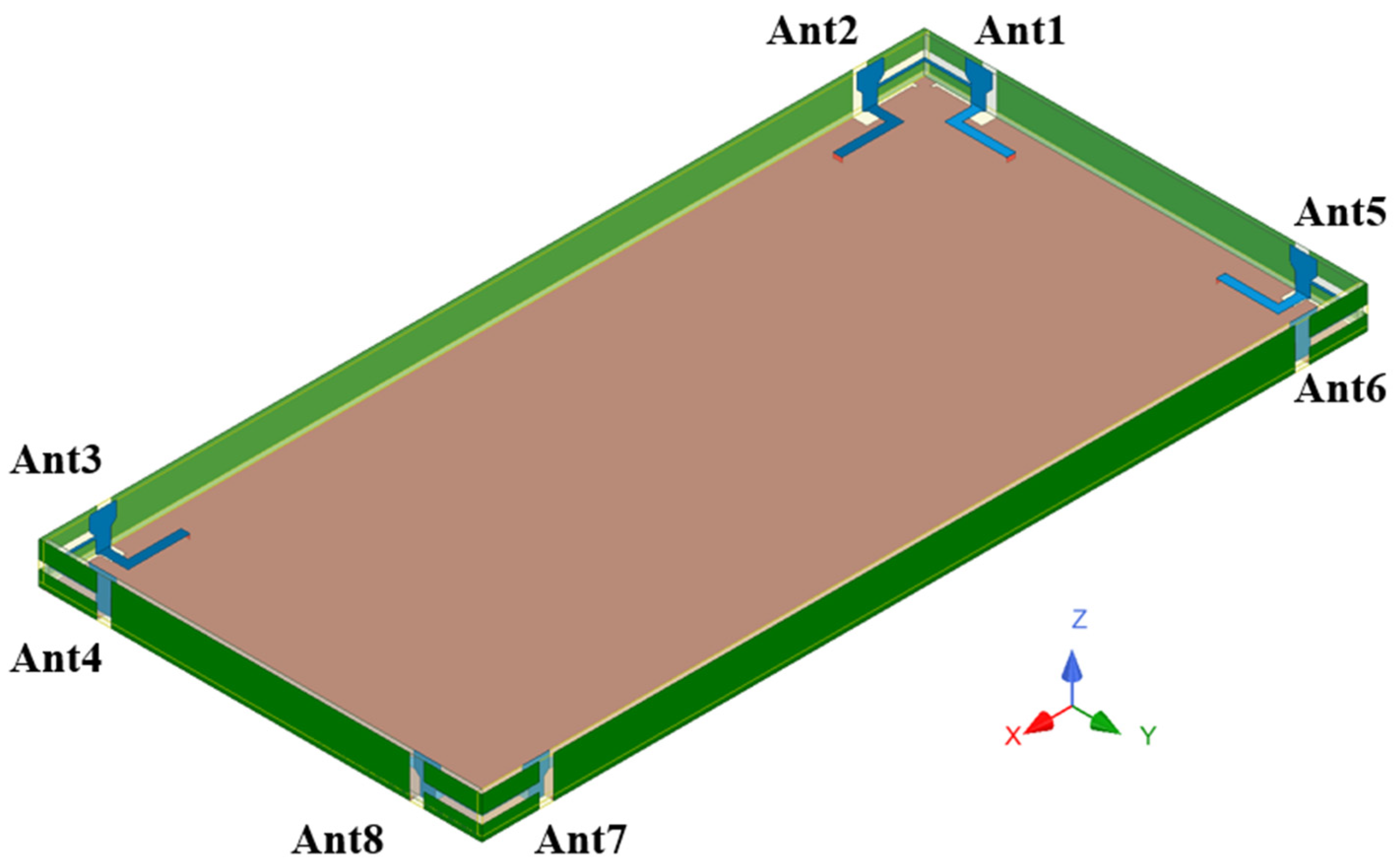
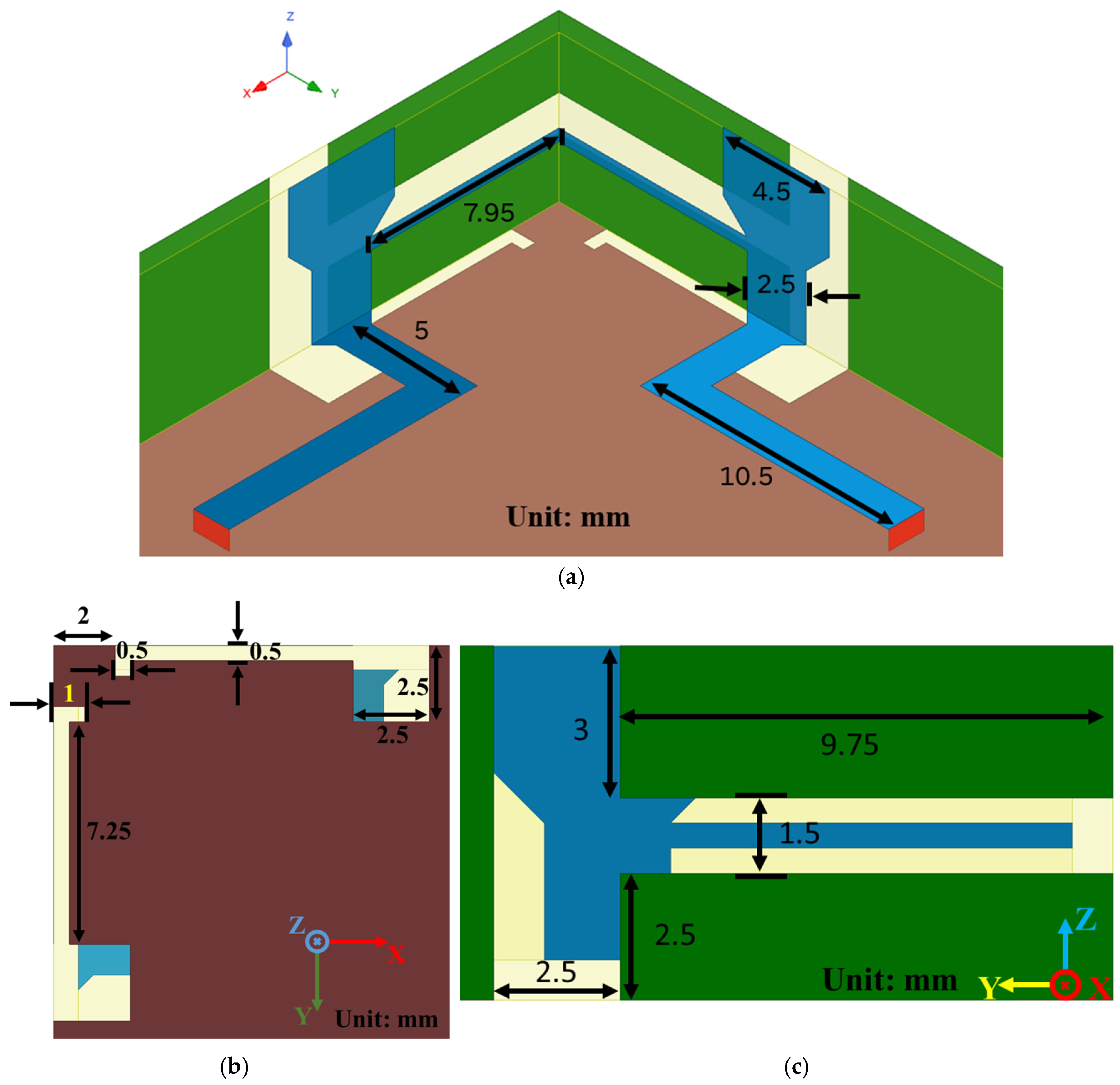
Figure 1 shows that the 8 × 8 MIMO antenna array was arranged on those four corners in a symmetrical design on the mobile phone with the metal frame and shell. The phone dimensions were 150 mm × 75 mm × 7 mm, and it was constructed from an FR4 substrate with a relative dielectric constant of 4.4 and loss tangent of 0.02. Each corner of the mobile phone had two antennas with a neutral line for decoupling. The antennas were strategically placed in the corners, effectively streamlining the internal component space on the PCB board. This approach achieved a compact antenna. The open-slot antenna element was composed of two slot antennas: one straight and one L-shaped. The straight-slot antenna started from the mobile phone’s edge to the ground plane. The L-shaped slot antenna connected the straight-slot antenna on the ground plane. The open-slot antenna element was coupled by a T-shaped structure with a 50-Ω transmission line. The detailed parameters of the proposed open-slot antenna are shown in Figure 2. The antenna element dimensions were 12.25 mm × 2.5 mm × 7 mm. A neutral line of 15.9 mm × 0.5 mm connected these T-shape coupling structures, and a wide slot of 19.5 mm × 1.5 mm was etched on the back side of the neutral line. These structures served as the decoupling components for the two slot antenna elements.

Figure 1.
Arrangement of the proposed 8 × 8 MIMO antenna array in a mobile phone.
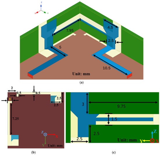
Figure 2.
The (a) front view, (b) bottom view, and (c) side view of these two adjacent antennas.
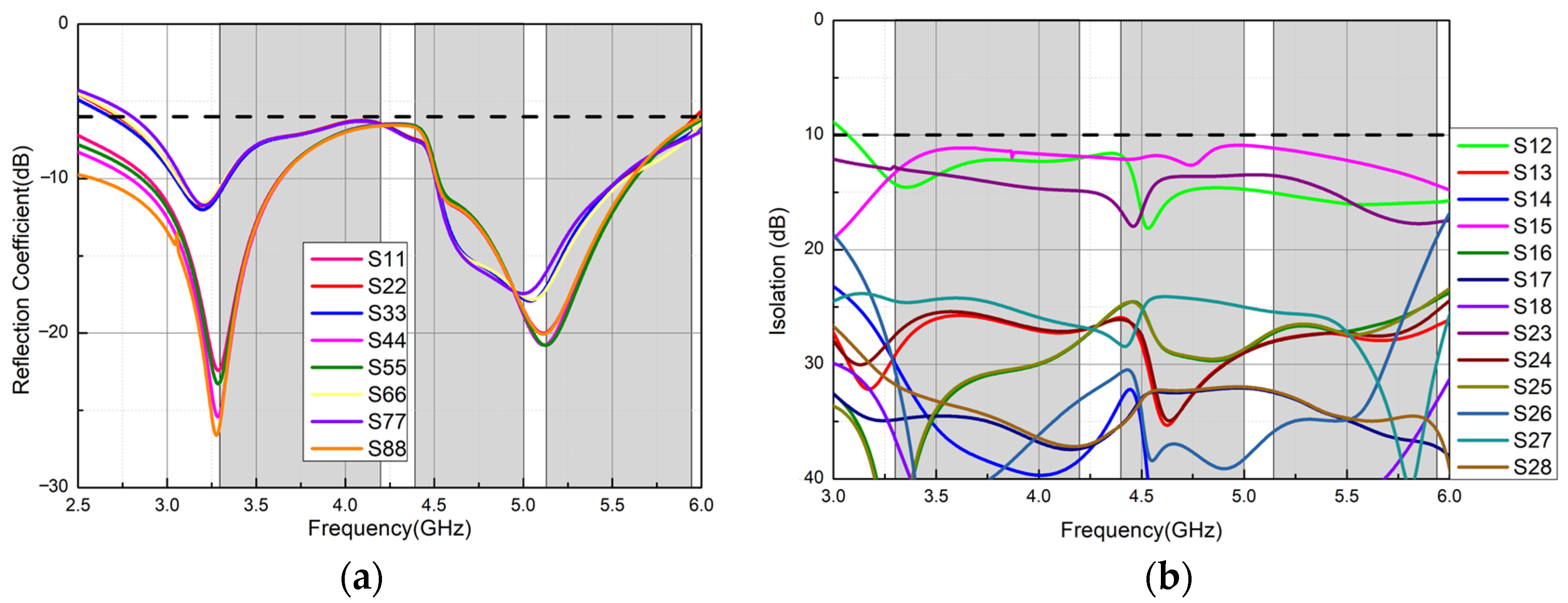
Figure 3 shows the simulated S parameters of the MIMO antenna array. The gray parts in Figure 3 present the frequency bands of the n77/78/79 and WiFi-5GHz bands. Figure 3a shows the reflection coefficients (S11) of these antennas. Figure 3a shows that the 6 dB impedance bandwidth, which is from 2.8 to 6 GHz, of the proposed antenna was formed by two resonating modes around 3.3 and 5.15 GHz. These two resonating modes were excited by the L-shaped slot antenna (the lower one) and the straight-slot antenna (the high one). Figure 3b shows the isolations of these proposed slot antennas each other. All isolations representing mutual coupling were higher than 12 dB in between 3.2 to 6 GHz. Here, only the isolations between Ant.1, Ant.2, and other antennas are shown because the antenna pairs were symmetrically arranged in four corners. As we can see, the S23 and S15 are higher than the others besides the S12. That is because Ant.2 and Ant.3 were put on the same side of the mobile phone and those two antennas have the same polarization. Ant.1 and Ant.5 have the same reason.
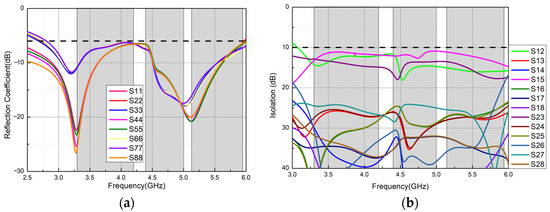
Figure 3.
(a) Reflection coefficients and (b) isolations with the neutral line of the proposed MIMO antenna array.
2.2. Antenna Design Process
2.2.1. Analyses of the Single Antenna
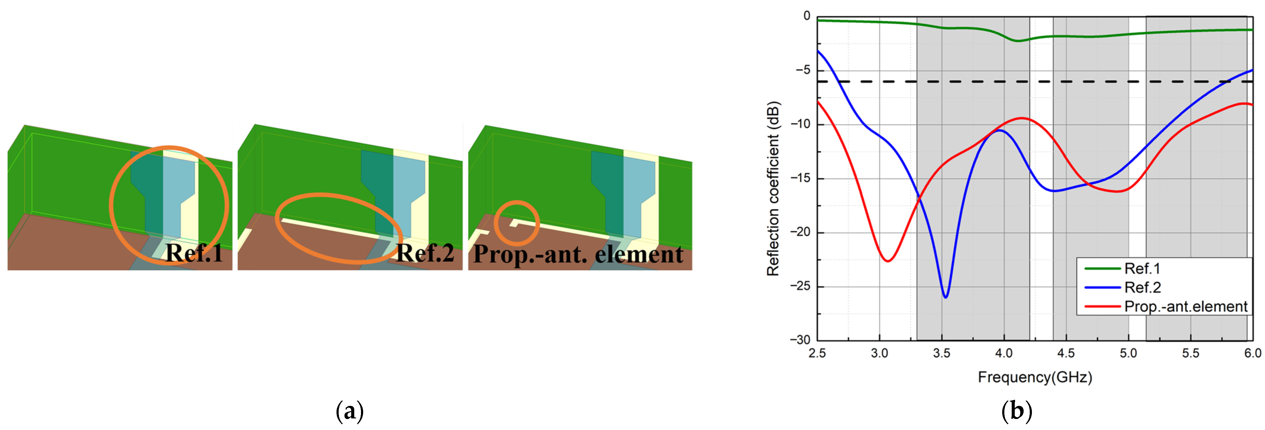
The design process of the antenna element is shown in Figure 4a. Figure 4b presents the simulated reflection coefficients. Ref.1 was composed of a T-shaped feeding structure and an open-slot antenna. The green line in Figure 4b represents the simulated reflection coefficient of Ref.1. It can be observed that there was a resonant frequency mode at about 4.1 GHz, even though the impedance matching was not good. A long slot on the ground plane connected to Ref.1 to form Ref.2. This introduced a new resonating frequency mode at around 3.5 GHz and improved the overall impedance matching, as shown in the blue line in Figure 4b. We can see that there were two resonating frequencies, which were at 3.5 and 4.3 GHz of Ref.2, and two impedance bandwidths. However, the WiFi-5GHz band was still not covered. Then, adding a short slot to the end of the long slot of Ref.2 perpendicularly formed the proposed single-antenna (Prop.-ant.) element. The red line in Figure 4b illustrates the simulated reflection coefficient of the proposed single-antenna element. The original low-resonating mode at 3.5 GHz was moved to 3.1 GHz, and the high-resonating mode at 4.3 GHz moved to 5 GHz. It also enlarged the impedance bandwidth of the high band to cover the WiFi-5GHz band. The 6 dB impedance bandwidth covered these n77/78/79 and WiFi-5GHz bands.

Figure 4.
(a) Design process of the antenna element and (b) the simulated reflection coefficients for Ref.1, Ref.2, and the proposed single-antenna element (prop.-ant. element).
2.2.2. Isolation Analysis
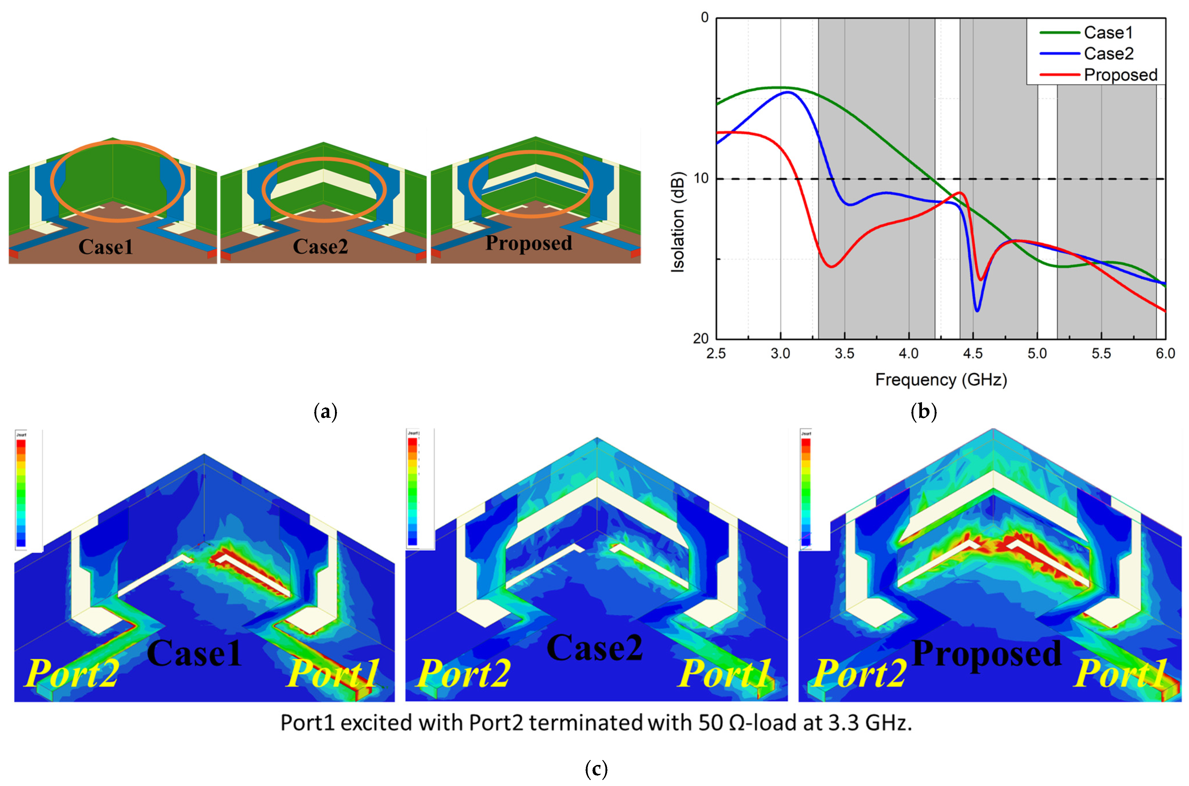
A slot and a neutral line were incorporated to reduce mutual coupling between two adjacent antennas. Figure 5a illustrates the design process of the decoupling structure. The first case features two proposed single-antenna elements, as illustrated in Figure 5a. The green line in Figure 5b illustrates the simulated isolation result and Figure 6c illustrates their corresponding surface current distributions. It can be seen that the isolation was not above 10 dB before 4.18 GHz. Then, in the second case, as shown in Figure 5a, a 1.5 mm wide slot was etched in the metal frame of the mobile phone. The isolation improvement at around 3.4 GHz is depicted by the blue line in Figure 5b. This wide slot was designed to prevent mutual coupling between the antennas; however, it did not fully cover all the operating frequency bands. As a result, a neutral line was introduced between two T-shaped feeding structures of the mobile phone called the proposed antenna, as shown in Figure 5a. The red line in Figure 5b is the isolation of the proposed antenna. It can be seen that the isolation significantly improved and remained above 10 dB after 3.15 GHz. Figure 5c shows that when Port1 was excited, Port2 was terminated with a 50 Ω load. In Case1, some current can be observed on the T-shaped feeding structure. However, in Case2, after adding the wide slot, the current distribution was shifted to the area above the wide slot in the metal frame, resulting in a reduction in current on the T-shaped feeding structure. Finally, with the introduction of the neutral line structure, the current was concentrated above the wide slot and on the neutral line. Therefore, in this case, the wide slot and the neutral line could serve as decoupling structures.

Figure 5.
(a) Design process of the decoupling components. (b) Isolation and its corresponding (c) surface current distributions for the simulated Case1, Case2, and the proposed case.
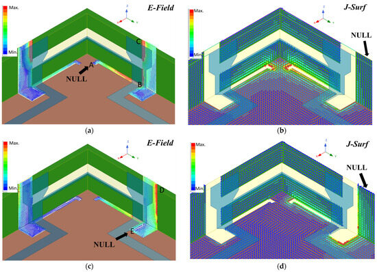
Figure 6.
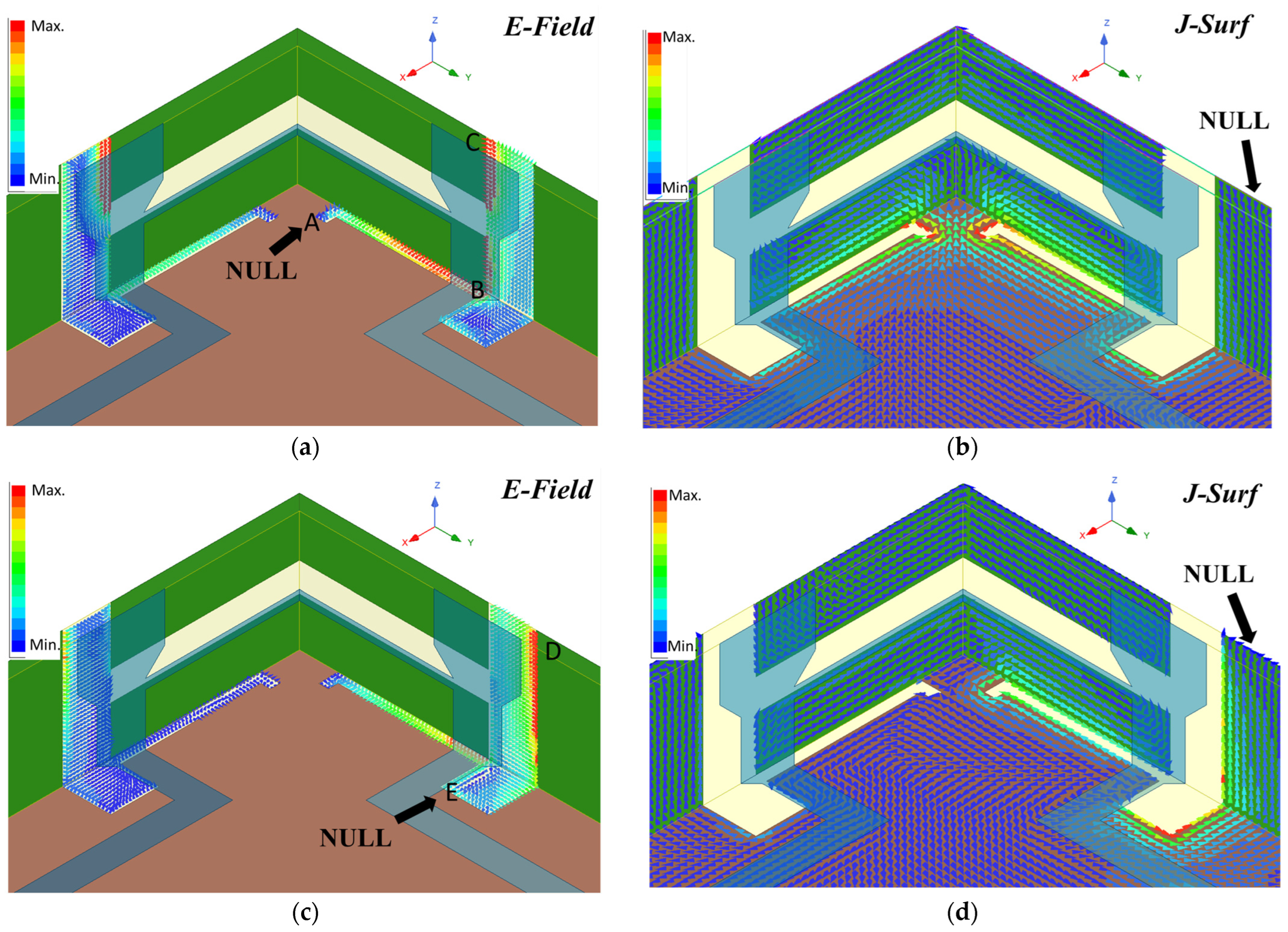
(a) Electric field, (b) surface current distribution at 3.3 GHz, (c) electric field, and (d) surface current distribution at 5 GHz of the proposed single-antenna element.
2.3. Surface Current and Electric Field Distributions
The simulated surface current (J-field) and electric field (E-field) distributions at 3.3 and 5 GHz are shown in Figure 6. Figure 6a exhibits the E-field distribution in the L-shaped slot antenna from point A to point C.
There was a hot point at the open end of the L-shaped slot antenna (point C) and a null point at the closed end of the L-shaped slot antenna (point A). A hot point was located at the open end of the L-shaped slot antenna (point C), while a null point was at the closed end (point A). The simulated surface current distribution of the open-slot antenna at 3.3 GHz is illustrated in Figure 6b. The surface current and electric field had inverted distributions. The surface current hot point was at the closed end of the L-shaped slot antenna, while the null point was at the open end. This L-shaped slot antenna worked as a quarter-wavelength slot antenna mode for 3.3 GHz. Figure 6c exhibits the electric field of the slot antenna at 5 GHz. The strait slot antenna from point D to point E introduced a resonating frequency at 5 GHz. A hot point was located at the open end of the straight-slot antenna (point D), while a null point was at the closed end (point E). The simulated surface current distribution of the open slot antenna at 5 GHz is exhibited in Figure 6d. The surface current hot point was at the closed end of the straight-slot antenna, while the null point was at the open end. This straight-slot antenna operated in a quarter-wavelength slot antenna mode for 5 GHz.
3. Parametric Studies
Some dominant parameters for this proposed antenna will be discussed and analyzed in this section. The L-shaped slot antenna excited the low band, and its length was a quarter wavelength at 3.3 GHz. The length was dominant. Therefore, the first studied parameter was L1, the length of the L-shaped slot antenna, as shown in Figure 7a. The variations in L1 ranged from 7.25 to 8.25 mm with a 0.5 mm differences, and the corresponding reflective coefficients are shown in Figure 7b. As we can see from Figure 7b, when L1 increased, the resonance frequency in the low-frequency band decreased from 3.3 to 3.2 GHz. The impedance matching and the impedance bandwidth also became better and wider, respectively. The reflective coefficient in the high band was also slightly affected by L1 because the L-shaped slot antenna was connected to the straight-slot antenna. The input impedance in the high band was affected by changing the L-shaped slot antenna. However, when L1 equaled 8.25 mm in length, the S11 was not under 6 dB at around 4 GHz. Therefore, the final choice was L1 equaling 7.75 mm. Similarly, the length of the straight-slot antenna was a quarter wavelength of 5 GHz. Therefore, the length of the straight was also dominant for the straight-slot antenna. The length of the straight-slot antenna (L2), as shown in Figure 8a, was investigated, and its variations from 1.5 to 3.5 mm with a 1 mm difference. The simulated |S11|s of the variations in L2 are exhibited in Figure 8b. It can be observed that when the value of L2 increased from 1.5 to 3.5 mm, the resonating frequency in the high-frequency band shifted from 5.5 to 4.7 GHz. The best choice of L2 was 2.5 mm because the 6 dB impedance bandwidth of other choices did not cover the desired bands.
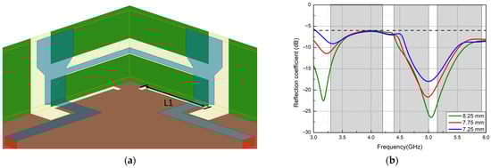
Figure 7.
(a) The geometry of and (b) variation in the reflection coefficient of parameter L1.
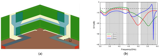
Figure 8.
(a) The geometry of and (b) variation in the reflection coefficient of parameter L2.
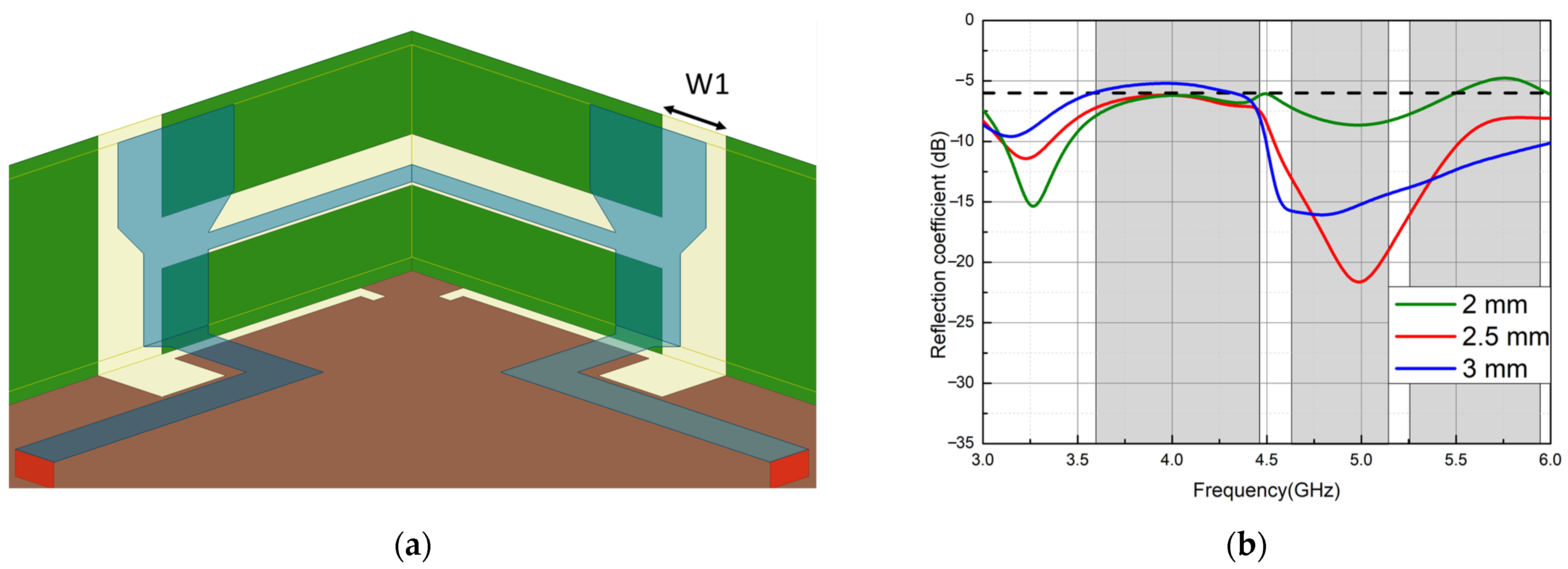
Because the width of the slot antenna will determine the impedance, the third parameter was chosen as the width, W1, of the slot antenna, as shown in Figure 9a. Figure 9b illustrates the corresponding |S11|s in the variations in W1. The W1 ranged from 2 to 3 mm with a 0.5 mm difference. When W1 equaled 2 mm, the impedance matching did not fall below 6 dB at around 5.7 GHz, as indicated by the green line in Figure 9b. It can be seen that the red line, which represents W1 equal to 3 mm in Figure 9b, had good impedance matching at the high-frequency band but worse at the low-frequency band. Therefore, W1 equaling 2.5 mm was a proper choice.
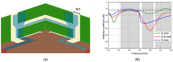
Figure 9.
(a) The geometry of and (b) variation in the reflection coefficient of parameter W1.
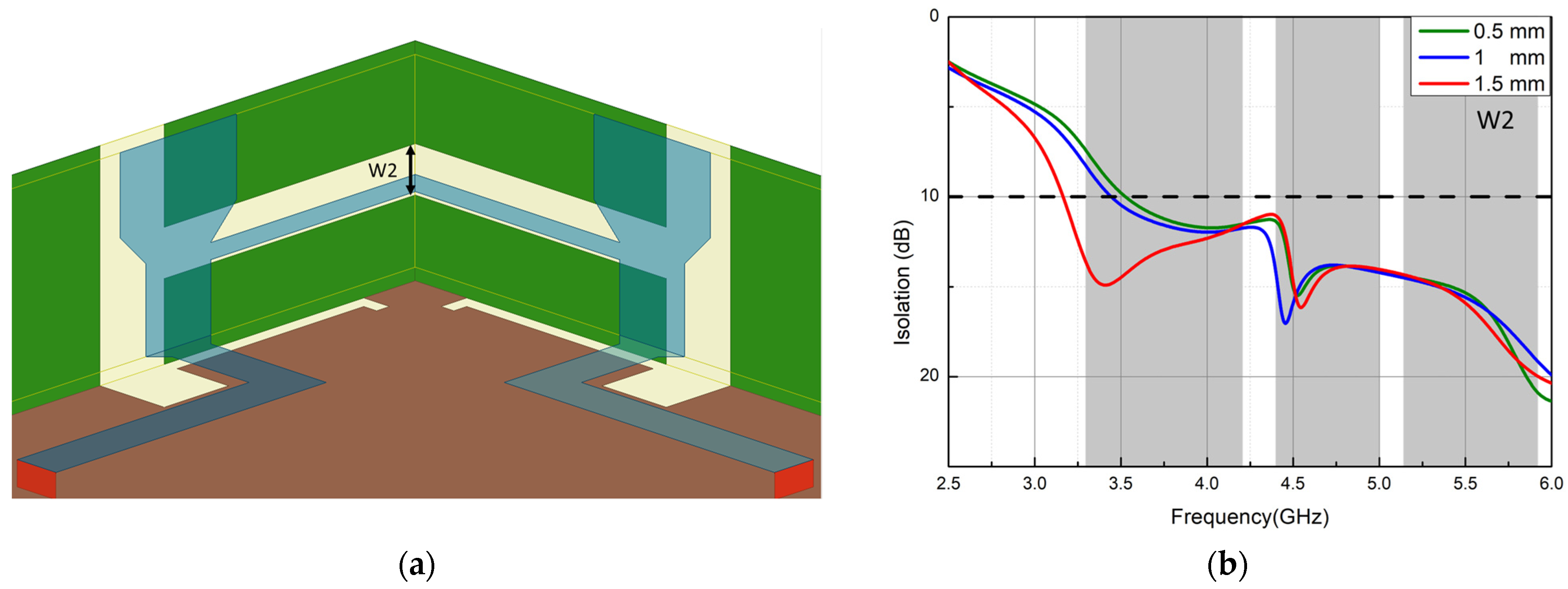
Then, the gap (W2), which is the width of a slot behind the neutral line in the metal frame, will be discussed, as shown in Figure 10a, because the gap may or may not overlap with the neutral line. The gap was from 0.5 to 1.5 mm with a 0.5 mm difference. When the gap widened, the isolation of each pair of antennas became better, which also signified a reduction in mutual coupling between adjacent antennas. When the W2 equaled to 1.5 mm, the bandwidth of 10 dB isolation began from 3.2 GHz and covered the desired band, as indicated by the red line in Figure 10b.
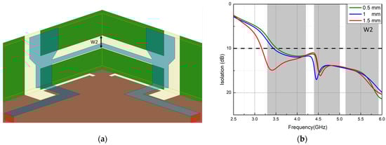
Figure 10.
(a) The geometry of and (b) variation in the isolation of parameter W2.
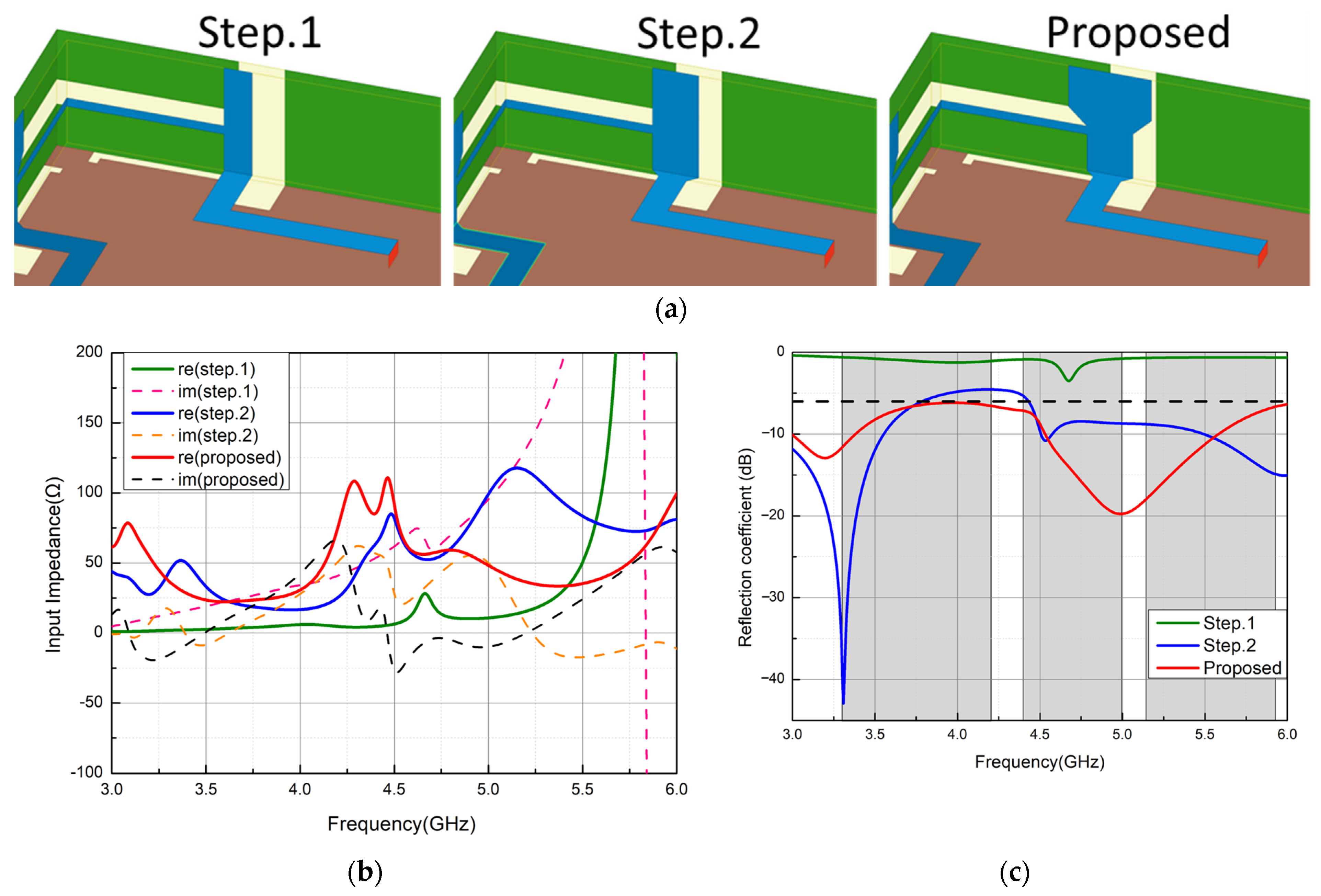
Figure 11a illustrates the variations in the T-shaped feeding structure. In step 1, the feeding structure consisted of a rectangular strip line that was 1.5 mm wide, as shown in Figure 11a. These simulated real parts and imaginary parts of the impedance are the green solid lines and pink dashed lines, as shown in Figure 11b. The resistance was very low, from 3.3 to 5.3 GHz. The resistance was close to the 50 Ω at around 5.5 GHz, but had a huge inductance. Therefore, the impedance matching was worse in this step, as shown by the green line in Figure 11c. In step 2, the 1.5 mm wide rectangular strip line was widened to 2.5 mm, as shown in Figure 11a. The blue solid and orange dashed lines in Figure 11b depict the real and imaginary parts of the input impedance of the antenna in step 2. It can be observed that the resistance rose at 3.3 GHz in the low-frequency band and 4.75 GHz in the middle-frequency band, and the inductance reduced at these frequencies. The simulated S11 of the antenna in step 2 is indicated by the blue line in Figure 11c. As shown, there was excellent impedance matching at 3.3 GHz, and the 6 dB impedance bandwidth, starting at 4.45 GHz, almost covered the middle- and high-frequency bands. However, the 6 dB impedance bandwidth did not cover all the desired bands. S11 did not fall below 6 dB from 3.8 to 4.45 GHz. Finally, the proposed antenna widened the upper half of the 2.5 mm wide rectangular strip line, as shown in Figure 11a. The simulated real and imaginary parts of the input impedance of the proposed antenna are the red solid lines and black dashed lines, as shown in Figure 11b. The resistance raised a little, at around 3.1 and 4.3 GHz, but there was good resistance from 4.6 to 5.8 GHz, and the reactance became small. From the red line in Figure 11c, we can see that the impedance matching at 3.3 GHz was worse than it was at step 2, but impedance matching was under 6 dB. The 6 dB impedance bandwidth of the proposed antenna covered all the desired bands (n77/78/79 and WiFi-5GHz bands).
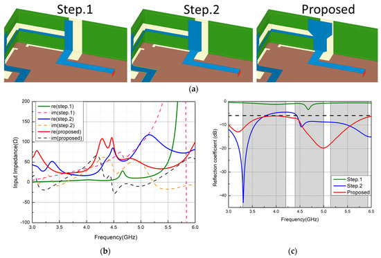
Figure 11.
The variations in the T-shape feeding structure in (a) step 1, step 2, and the proposed case; and (b) the variation in the input impedance and its corresponding (c) reflection coefficient.
4. Results and Discussion
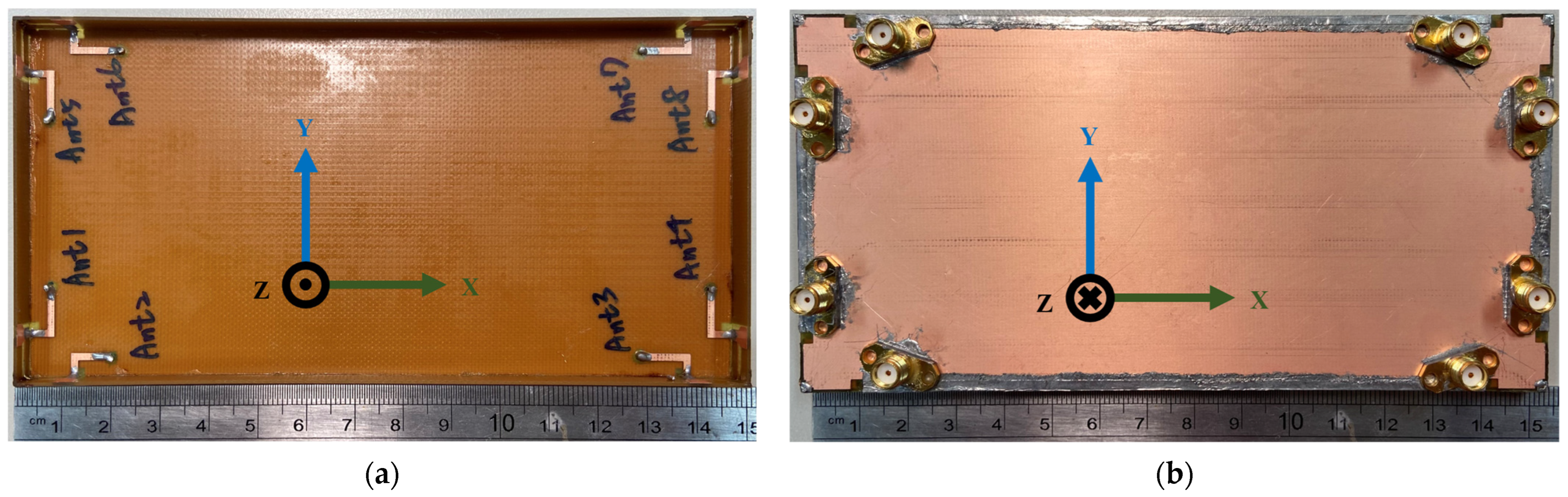
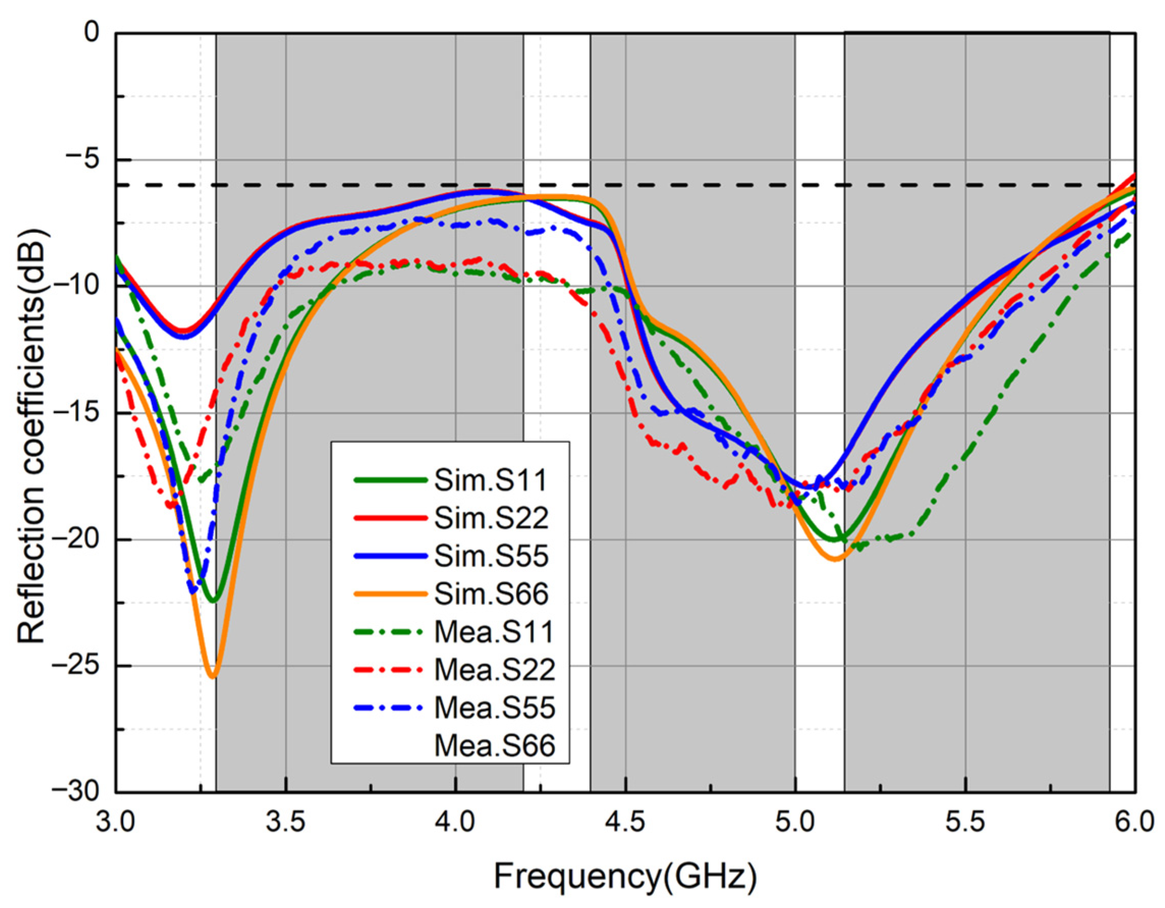
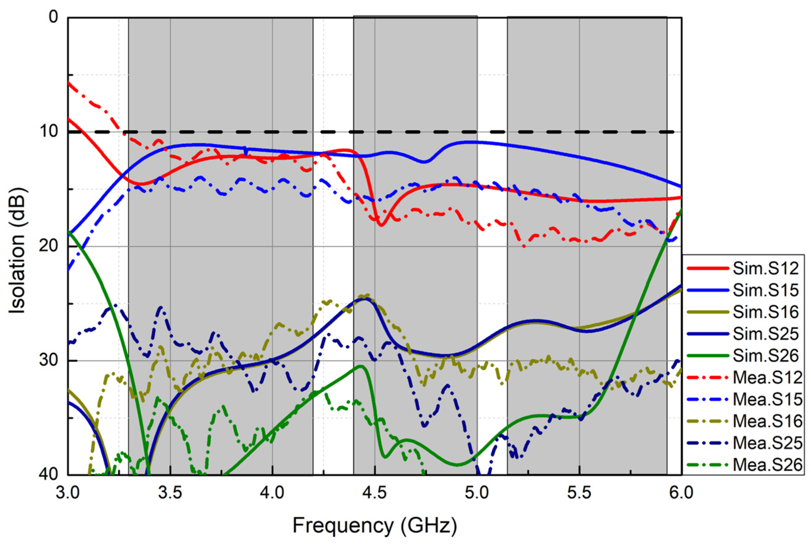
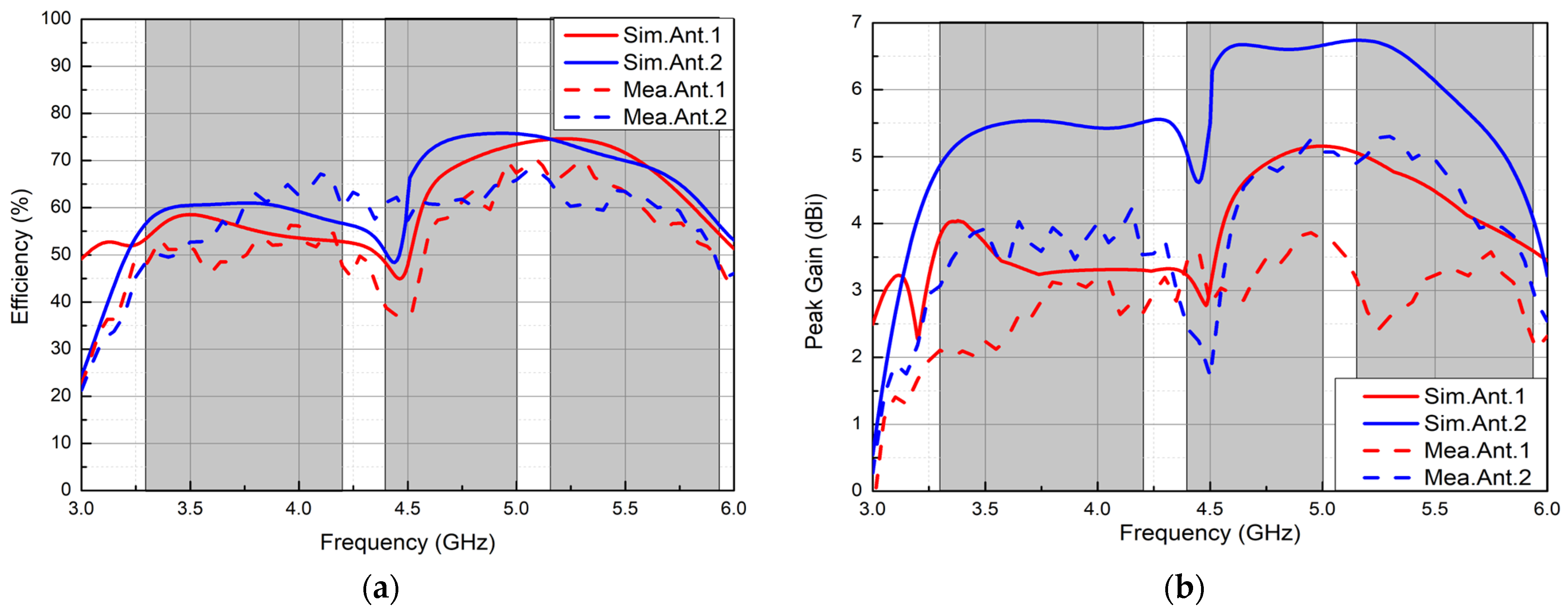
The proposed 8 × 8 MIMO antenna array was fabricated, and photographs of the front and back views are shown in Figure 12a and Figure 12b, respectively. The simulated and measured reflection coefficients of the proposed antenna are shown in Figure 13. Only the results of Ant.1, 2, 5, and 6 are shown in Figure 13 because the arrangement of these antennas was systematical to Ant.4, 3, 8, and 7. The gray parts in Figure 13 indicate n77, n78, n79, and WiFi-5GHz bands. The dashed lines of the measured result are mostly the same as the solid lines of the simulation result, and all of them can cover the expected frequency bands. A slight influence attributed to manufacturing tolerances and imperfection in soldering can be observed between the simulation and measurement. The simulated and measured isolations were similar, as shown in Figure 14. The isolations between Ant.1 and Ant.2, 5 and 6 (S12, S15, and S16), and between Ant.2 and Ant.5 and 6 (S25 and S26) are shown for representation because the antennas were arranged symmetrically in the mobile phone. The measured isolations remained above 10 dB after 3.3 GHz. Figure 15a,b shows the simulated and measured total efficiencies and peak realized gains. Because the arrangement of the antennas in a mobile phone was symmetrical, only the results of Ant.1 and 2 are exhibited for representation here. Both the simulated and measured results are illustrated by solid and dashed lines, respectively. It is noteworthy that the efficiency and gain at 3.3 GHz were slightly lower than those at 5 GHz. This phenomenon can be attributed to the mutual coupling of ground currents at 3.3 GHz, as evident from Figure 6b. The currents at the top and button were in the opposite direction. This will make the radiation fields cancel each other. The measured total efficiency and the peak realized gain ranged from 37 to 71% and 2 to 5.28 dBi, respectively. The trend of the measurements and simulations was exactly the same. The comparison of the proposed antenna and the reference in metal environments is depicted in Table 1. The proposed antenna had the smallest size and broad bandwidth.

Figure 12.
Photos of the manufactured MIMO antenna array: (a) top view and (b) back view.
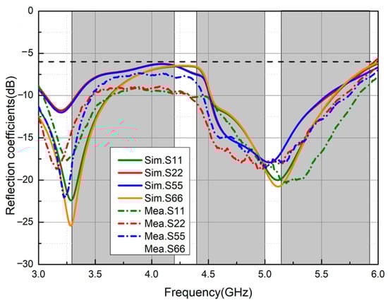
Figure 13.
Simulated and measured reflection coefficients for Ant.1, Ant.2, Ant.3, and Ant.4.
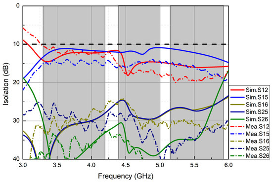
Figure 14.
Simulated and measured isolations of the proposed antenna.
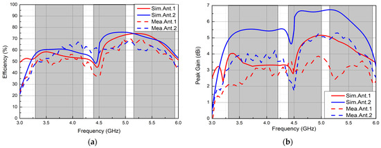
Figure 15.
Simulated and measured (a) efficiencies and (b) peak realized gains of the proposed antenna.

Table 1.
Comparison of the proposed antenna and the references.
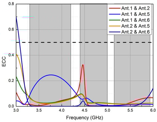
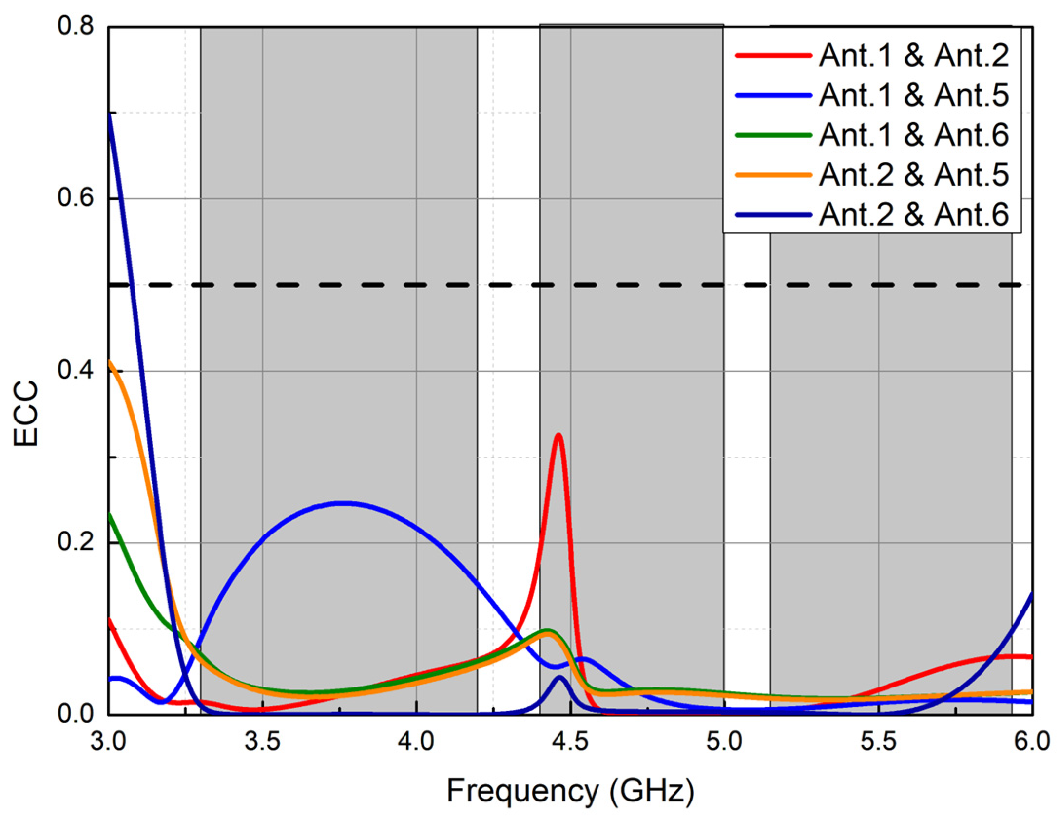
Figure 16.
Calculated ECC of the proposed antenna.
The values of ECCs are less than 0.34 and are smaller than the acceptable criterion level of 0.5. The CC value can be calculated by [23]
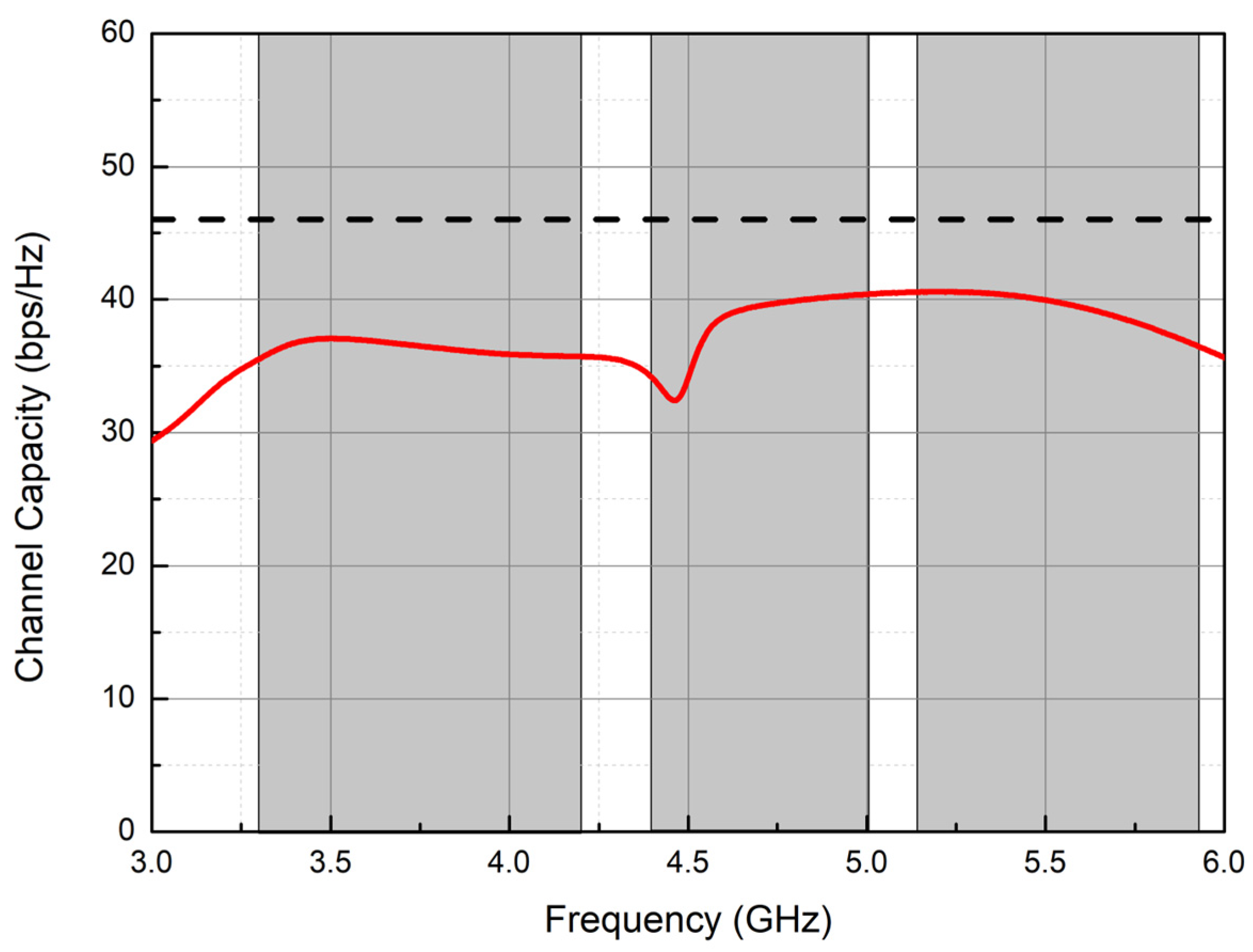
The calculating and ideal CCs are exhibited by the red solid and dash lines, respectively, in Figure 17 [8]. The upper limit value was 46 of the 8 × 8 MIMO antenna array. The range of the calculating CC was from 33 to 41 bps/Hz.
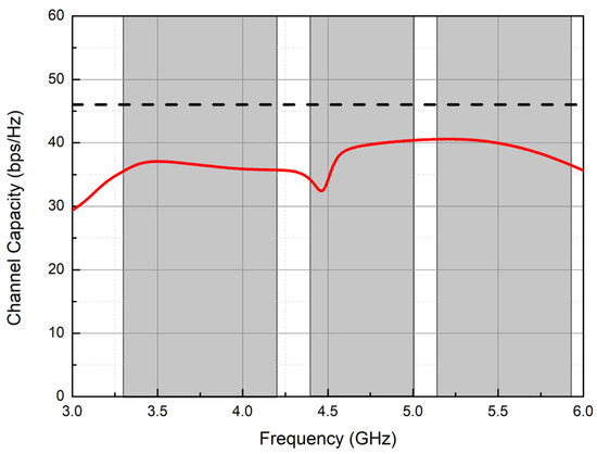
Figure 17.
Calculated channel capacity of the proposed antenna is the red line and the black dash line is the ideal CC value.
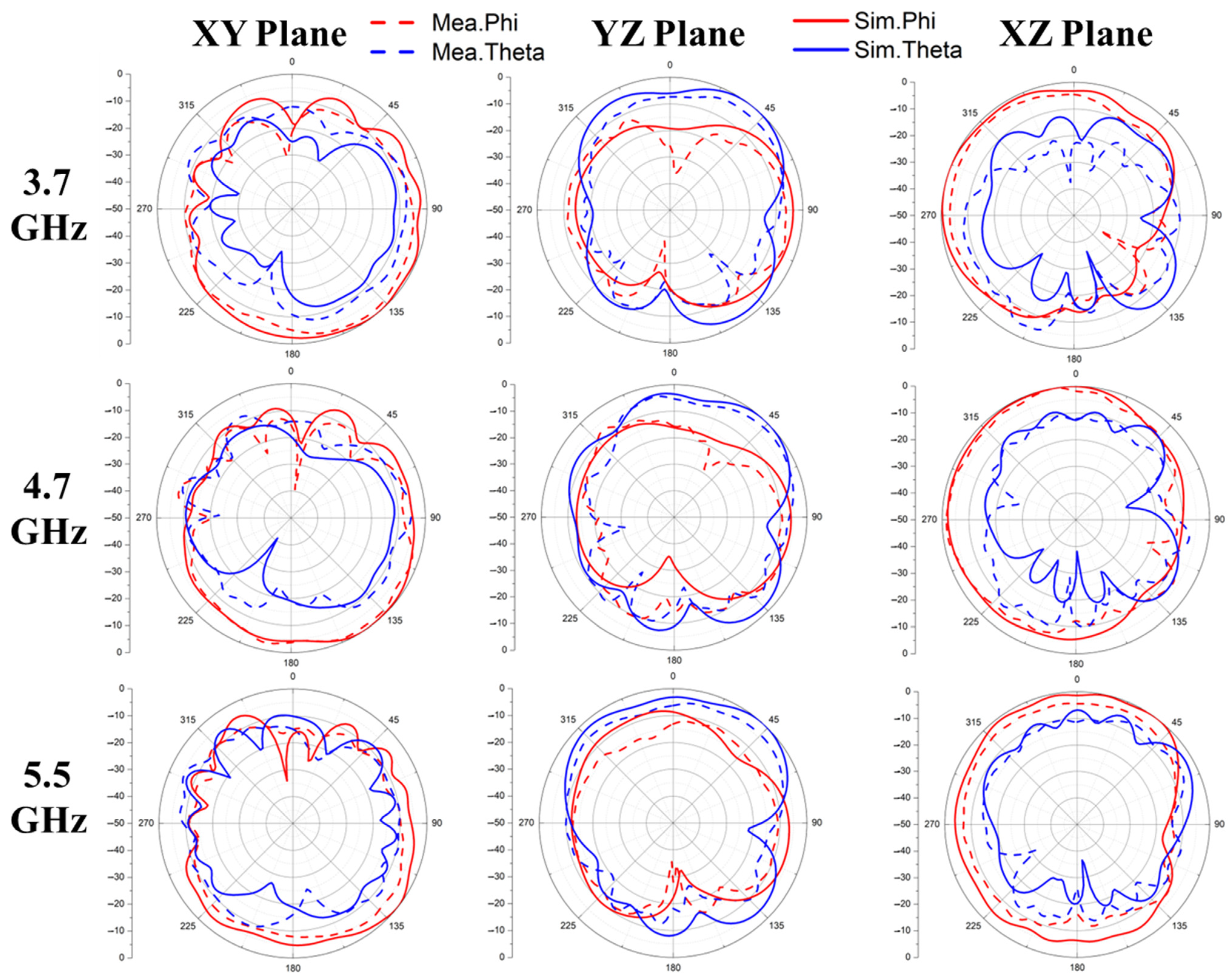
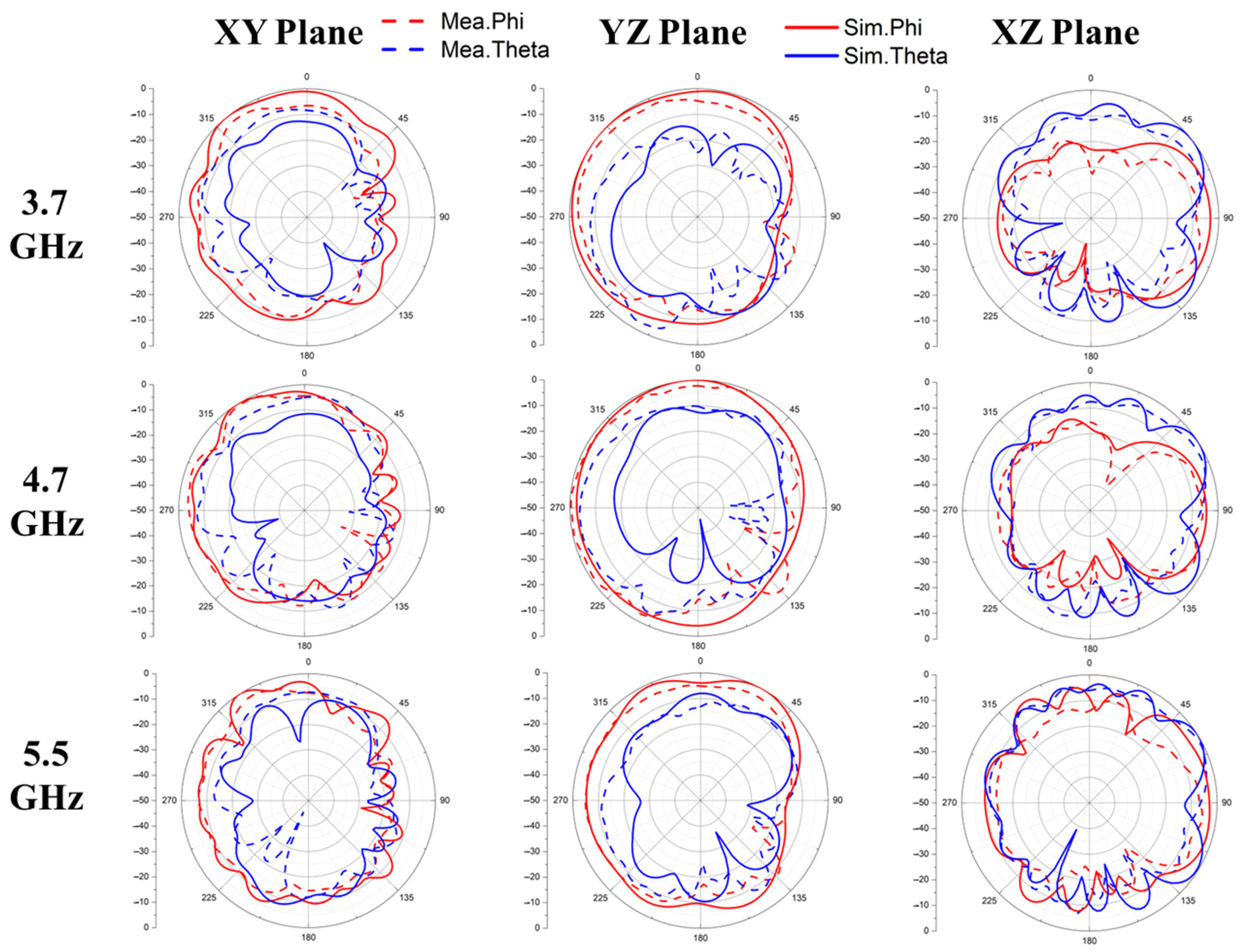
Figure 18 and Figure 19 show the normalized 2D radiation patterns excited by Ant.1 and Ant.2 at 3.7, 4.7, and 5.5 GHz, respectively. It is observed that the radiation patterns of Ant.1 in the XZ-plane and of Ant.2 in the YZ-plane were nearly omnidirectional at three frequencies, 3.7, 4.7, and 5.5 GHz, because both Ant.1 and Ant.2 are slot antennas laid in y- and x-direction, respectively.
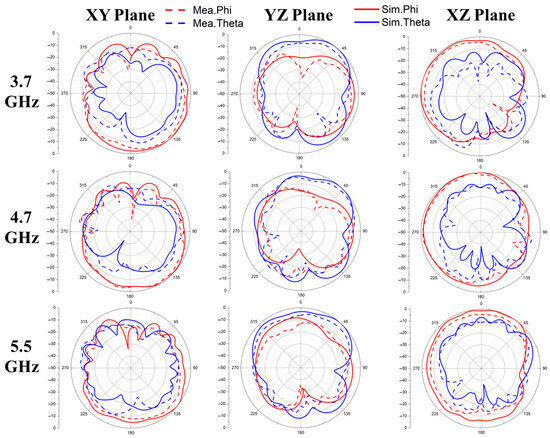
Figure 18.
The measured and simulated 2D radiation patterns of Ant.1 in the XY, YZ, and XY planes at 3.7, 4.7, and 5.5 GHz.
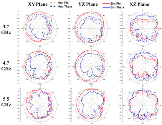
Figure 19.
The measured and simulated 2D radiation patterns of Ant.2 are in the XY, YZ, and XY planes at 3.7, 4.7, and 5.5 GHz.
5. Conclusions
This article presents a broad-bandwidth and compact-size 8 × 8 MIMO antenna array for 5G metal-frame mobile phone applications. The addition of a wide slot and a neutral line between two adjacent antennas for decoupling made isolation higher than 12 dB. The proposed single-antenna element consists of a straight-slot antenna with an L-shaped slot branch. The operating bandwidth ranged from 3.3 to 6 GHz and covered the n77/78/79 and WiFi-5GHz bands. The calculated ECC was less than 0.34, whereas the CC was from 33 to 41 bps/Hz. The measured peak realized gain and efficiency were between 2 and 5.28 dBi, and between 37 and 71%, respectively. The 2D radiation patterns exhibited nearly omnidirectional characteristics. With its strategically placed corner design, the proposed antenna is suitable for simplifying the internal structure of the PCB board in 5G mobile phone applications.
Author Contributions
Conceptualization, Y.-T.C. and H.-L.S.; methodology, Y.-T.C. and H.-L.S. software, Y.-T.C.; validation, Y.-T.C.; formal analysis, Y.-T.C.; investigation, Y.-T.C.; resources, Y.-T.C.; data curation, Y.-T.C.; and writing—original draft preparation, Y.-T.C.; writing—review and editing, H.-L.S.; visualization, H.-L.S.; supervision, H.-L.S.; project administration, H.-L.S.; funding acquisition, H.-L.S. All authors have read and agreed to the published version of the manuscript.
Funding
This work was partially supported by the National Science and Technology Council (Taiwan) and the National Pingtung University. The project numbers for the NSTC are NSTC 112-2221-E-153-005 and 113-2914-I-153-011-A1.
Data Availability Statement
All data are contained within this article.
Acknowledgments
The authors thank the TSRI (Taiwan Semiconductor Research Institute) for supporting antenna measurement.
Conflicts of Interest
The authors declare no conflicts of interest.
References
- Huang, D.; Du, Z.; Wang, Y. A Quad-Antenna System for 4G/5G/GPS Metal Frame Mobile Phones. IEEE Antennas Wirel. Propag. Lett. 2019, 18, 1586–1590. [Google Scholar] [CrossRef]
- Choi, J.; Hwang, W.; You, C.; Jung, B.; Hong, W. Four-Element Reconfigurable Coupled Loop MIMO Antenna Featuring LTE Full-Band Operation for Metallic-Rimmed Smartphone. IEEE Trans. Antennas Propag. 2019, 67, 99–107. [Google Scholar] [CrossRef]
- Liu, Y.; Cui, W.; Jia, Y.; Ren, A. Hepta-Band Metal-Frame Antenna for LTE/WWAN Full-Screen Smartphone. IEEE Antennas Wirel. Propag. Lett. 2020, 19, 1241–1245. [Google Scholar] [CrossRef]
- Liu, Y.; Zhou, Y.-M.; Liu, G.-F.; Gong, S.-X. Heptaband Inverted-F Antenna for Metal-Rimmed Mobile Phone Applications. IEEE Antennas Wirel. Propag. Lett. 2016, 15, 996–999. [Google Scholar] [CrossRef]
- Qiu, P.; Feng, Q. Low-Profile Compact Antenna for Octa-Band Metal-Rimmed Mobile Phone Applications. IEEE Trans. Antennas Propag. 2020, 68, 54–61. [Google Scholar] [CrossRef]
- Chang, L.; Yu, Y.; Wei, K.; Wang, H. Polarization-Orthogonal Co-frequency Dual Antenna Pair Suitable for 5G MIMO Smartphone with Metallic Bezels. IEEE Trans. Antennas Propag. 2019, 67, 5212–5220. [Google Scholar] [CrossRef]
- Sun, L.; Li, Y.; Zhang, Z. Wideband Decoupling of Integrated Slot Antenna Pairs for 5G Smartphones. IEEE Trans. Antennas Propag. 2021, 69, 2386–2391. [Google Scholar] [CrossRef]
- Chen, S.-C.; Chou, L.-C.; Hsu, C.-I.G.; Li, S.-M. Compact Sub-6-GHz Four-Element MIMO Slot Antenna System for 5G Tablet Devices. IEEE Access 2020, 8, 154652–154662. [Google Scholar] [CrossRef]
- Chen, Q.; Lin, H.; Wang, J.; Ge, L.; Li, Y.; Pei, T. Single Ring Slot-Based Antennas for Metal-Rimmed 4G/5G Smartphones. IEEE Trans. Antennas Propag. 2019, 67, 1476–1487. [Google Scholar] [CrossRef]
- Yuan, X.-T.; He, W.; Hong, K.-D.; Han, C.-Z.; Chen, Z.; Yuan, T. Ultra-Wideband MIMO Antenna System with High Element-Isolation for 5G Smartphone Application. IEEE Access 2020, 8, 56281–56289. [Google Scholar] [CrossRef]
- Cai, Q.; Li, Y.; Zhang, X.; Shen, W. Wideband MIMO Antenna Array Covering 3.3–7.1 GHz for 5G Metal-Rimmed Smartphone Applications. IEEE Access 2019, 7, 142070–142084. [Google Scholar] [CrossRef]
- Chen, H.-D.; Tsai, Y.-C.; Sim, C.-Y.-D.; Kuo, C. Broadband Eight-Antenna Array Design for Sub-6 GHz 5G NR Bands Metal-Frame Smartphone Applications. IEEE Antennas Wirel. Propag. Lett. 2020, 19, 1078–1082. [Google Scholar] [CrossRef]
- Alja’afreh, S.S.; Altarawneh, B.; Alshamaileh, M.H.; E’qab, R.A.; Hussain, R.; Sharawi, M.S.; Xing, L.; Xu, Q. Ten Antenna Array Using a Small Footprint Capacitive-Coupled-Shorted Loop Antenna for 3.5 GHz 5G Smartphone Applications. IEEE Access 2021, 9, 33796–33810. [Google Scholar] [CrossRef]
- Li, Y.; Sim, C.-Y.-D.; Luo, Y.; Yang, G. Multiband 10-Antenna Array for Sub-6 GHz MIMO Applications in 5-G Smartphones. IEEE Access 2018, 6, 28041–28053. [Google Scholar] [CrossRef]
- Lun, Y.; Zhang, G.; Li, Z.; Suo, J.; Yue, J.; Che, Z. A Compact 5G Dual-Band MIMO Antenna with Pattern Diversity for Mobile Phone. In Proceedings of the 2020 Cross Strait Radio Science & Wireless Technology Conference (CSRSWTC), Fuzhou, China, 13–16 December 2020. [Google Scholar]
- Yang, K. Research and Design of a High Isolation 5G Antenna for Smart Phone. In Proceedings of the 2020 3rd International Conference on Information and Computer Technologies (ICICT), San Jose, CA, USA, 9–13 March 2020. [Google Scholar]
- Satyanarayana, B.; Srivastava, S.K.; Meshram, M.K. Eight-Element Dual-Band MIMO Antenna System for Sub-6 GHz 5G Smartphone Applications. In Proceedings of the 2019 IEEE Indian Conference on Antennas and Propagation (InCAP), Ahmedabad, India, 19–22 December 2019. [Google Scholar]
- Deng, C.; Lv, X. Eight-element MIMO Antenna with Tightly-arranged Pairs for 5G Mobile Terminal. In Proceedings of the 2019 IEEE International Symposium on Antennas and Propagation and USNC-URSI Radio Science Meeting, Atlanta, GA, USA, 12–14 July 2019. [Google Scholar]
- Jaglan, N.; Gupta, S.D.; Sharawi, M.S. 18 Element Massive MIMO/Diversity 5G Smartphones Antenna Design for Sub-6 GHz LTE Bands 42/43 Applications. IEEE Open J. Antennas Propag. 2021, 2, 533–545. [Google Scholar] [CrossRef]
- Wong, K.-L.; Chen, Y.-H.; Li, W.-Y. Decoupled compact ultra-wideband MIMO antennas covering 3300~6000 MHz for the fifth-generation mobile and 5GHz-WLAN operations in the future smartphone. Microw. Opt. Technol. Lett. 2018, 60, 2345–2351. [Google Scholar] [CrossRef]
- Serghiou, D.; Khalily, M.; Singh, V.; Araghi, A.; Tafazolli, R. Sub-6 GHz Dual-Band 8 × 8 MIMO Antenna for 5G Smartphones. IEEE Antennas Wirel. Propag. Lett. 2020, 19, 1546–1550. [Google Scholar] [CrossRef]
- TaiwanJaglan, N.; Gupta, S.D.; Kanaujia, B.K.; Sharawi, M.S. 10 Element Sub-6-GHz Multi-Band Double-T Based MIMO Antenna System for 5G Smartphones. IEEE Access 2021, 9, 118662–118672. [Google Scholar]
- Ahmad, U.; Ullah, S.; Rafique, U.; Choi, D.-Y.; Ullah, R.; Kamal, B.; Ahmad, A. MIMO Antenna System with Pattern Diversity for Sub-6 GHz Mobile Phone Applications. IEEE Access 2021, 9, 149240–149249. [Google Scholar] [CrossRef]


Disclaimer/Publisher’s Note: The statements, opinions and data contained in all publications are solely those of the individual author(s) and contributor(s) and not of MDPI and/or the editor(s). MDPI and/or the editor(s) disclaim responsibility for any injury to people or property resulting from any ideas, methods, instructions or products referred to in the content. |
© 2024 by the authors. Licensee MDPI, Basel, Switzerland. This article is an open access article distributed under the terms and conditions of the Creative Commons Attribution (CC BY) license (https://creativecommons.org/licenses/by/4.0/).