Article

Determinants of the Generation of Higher Current Harmonics in Different Operating States of the RGB LED Lamp

by
Kazimierz Kuryło
,
Wiesław Sabat
,
Dariusz Klepacki
*,
Kazimierz Kamuda
and
Piotr Jankowski-Mihułowicz
*
Department of Electronic and Telecommunication Systems, Rzeszow University of Technology, W. Pola 2, 35-959 Rzeszow, Poland
*
Authors to whom correspondence should be addressed.
Electronics 2024, 13(3), 531; https://doi.org/10.3390/electronics13030531
Submission received: 17 December 2023 / Revised: 21 January 2024 / Accepted: 25 January 2024 / Published: 28 January 2024

Abstract

:
This article deals with problems related to electromagnetic compatibility, which is a very important issue due to the fact of ensuring the proper coexistence of devices and systems in a given electromagnetic environment. The devices manufactured today can, on the one hand, be a source of electromagnetic disturbance emissions and, on the other hand, be susceptible to disturbance signals from the environment. A large group of receivers in which electronic specialised circuits are used are LED lamps. The operation of an RGB LED lamp due to higher harmonic current emissions has been analysed in this paper. Lamp tests were carried out in several stages. In each of them, the values of the generated higher harmonics were analysed and related to the parameters of the current flowing through the lamp. It was shown how the parameters of the current pulse affect the generated harmonics when the value of the luminous flux was changed, its colour was changed, or the built-in function was turned on. It is also shown how, for example, changing the value of an electronic component in the lamp’s power supply changes the parameters of the current and thus the value of the generated higher harmonics.

1. Introduction

1.1. Background

Electronic devices manufactured today are increasingly functional; they can perform selected utility functions automatically, thus relieving the burden on human activities. Furthermore, their design and the way they communicate on the road as the ‘user—device’ is well thought out and intuitive, and they are now (according to EU regulations) energy efficient devices. It should be noted that the aforementioned advantages of these devices, such as functionality, easy communication with the user, and energy efficiency, were made possible by the use of highly specialised electronic integrated circuits and microcontrollers. However, this is a group of electronic circuits that are sensitive to electromagnetic disturbance signals from the environment [1], and they themselves can be a source of the emission of disturbance signals in the electromagnetic environment [2,3,4].
The disturbance signals generated by electronic systems are characterised by a specific frequency that depends on the individually adopted design solutions of a given system. This means that different electronic systems can emit electromagnetic disturbances with their characteristic frequency. Therefore, electromagnetic compatibility emissivity testing of electrical and electronic equipment is carried out over a wide frequency range from 50 Hz to 1 GHz and in some cases above this value. The typical frequency ranges for which EMC equipment tests are conducted are shown in Table 1.

1.2. Literature Review

Electromagnetic compatibility tests conducted in the low-frequency range, i.e., from 50 Hz to 2.5 kHz, are concerned with higher current and voltage harmonics. Higher current harmonics are generated by receivers that have nonlinear current–voltage characteristics. Problems related to the current of nonlinear receivers in the power grid and the generation of higher harmonics are still very relevant. Commonly manufactured and used devices are equipped with controllable and non-controllable rectifiers, contactless power electronic switches, current and voltage inverters, electronic converters, etc., which must also be equipped with specialised electronic circuits that control their operation [5,6,7,8,9,10,11]. The devices mentioned above can, when not equipped with appropriate solutions, contribute to an increase in the impact of these devices on the electricity grid and on other consumers operating in the grid [12,13,14]. In other words, not only has the emission of higher harmonic currents become a problem, but also the emission of unwanted disturbance signals in a wide spectrum of frequencies in the environment (e.g., the industrial environment) in which other electrical and electronic devices operate [2,15,16]. As a result, they may operate in an unsteady way, the functions they perform may be altered, or, in extreme cases, these devices may be damaged. Therefore, the growing problem of the emission of unwanted disturbance signals has required preventive actions to reduce their value by using appropriate techniques, such as attaching appropriate input filters [17,18,19].
The dynamic development of electronics, mentioned above, has resulted in the current significant saturation of the residential environment with various types of electrical and electronic devices, which is particularly evident in larger urban areas. These are devices with small unit power ratings, such as household appliances, PCs, and indoor and outdoor lighting. They can be found in stores, large commercial buildings, or offices. Such devices can also generate electromagnetic disturbances [13,14,15,20]. It happens that the mentioned computers, household appliances, or lighting lamps available for sale do not meet EMC requirements. If there is a significant emission of low-frequency disturbances (i.e., higher harmonics of current), the power grid and the operation of other electrical and electronic equipment can be adversely affected.
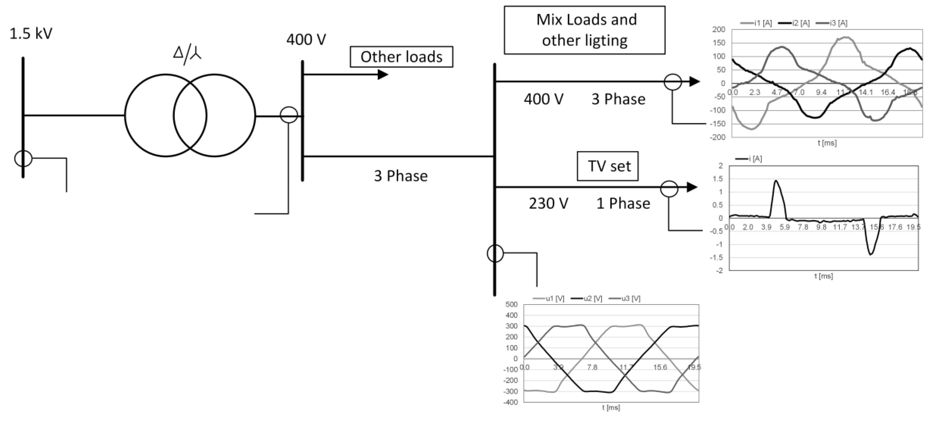
Higher harmonics of current [8,9,10] considered in the range from 50 Hz to 2.5 kHz are produced mainly by nonlinear receivers and are very often associated with the electric power system. This is because these types of loads draw distorted current [21] even when supplied with sinusoidal voltage. In practice, the low-voltage network usually has a distorted voltage. The voltage distortion is caused by the operation of non-linear loads installed in the distribution network. An example would be non-linear loads installed in a large commercial building, office building or housing estate. This can be seen by taking power quality measurements at the main switchboard supplying the building. An example of a distorted current and voltage waveform measured at the main switchboard serving a large apartment block is presented in Figure 1. Non-linear receivers installed in homes, i.e., PCs, TVs, lighting receivers, etc., can cause the distortion of the supply voltage. The first element to appear on the mains side in this type of receiver is the electronic power supply, which, if poorly designed (because it does not use circuits to limit higher current harmonics), can be a source of higher current harmonics. This problem is described, for example, in [21,22]. The network supplying non-linear computer and lighting loads in a commercial building is illustrated in Figure 2.
One of the effects of the consumption of distorted current by non-linear loads is the distortion of the supply voltage. This is because harmonic currents cause additional voltage drops across the supply network impedance [10].
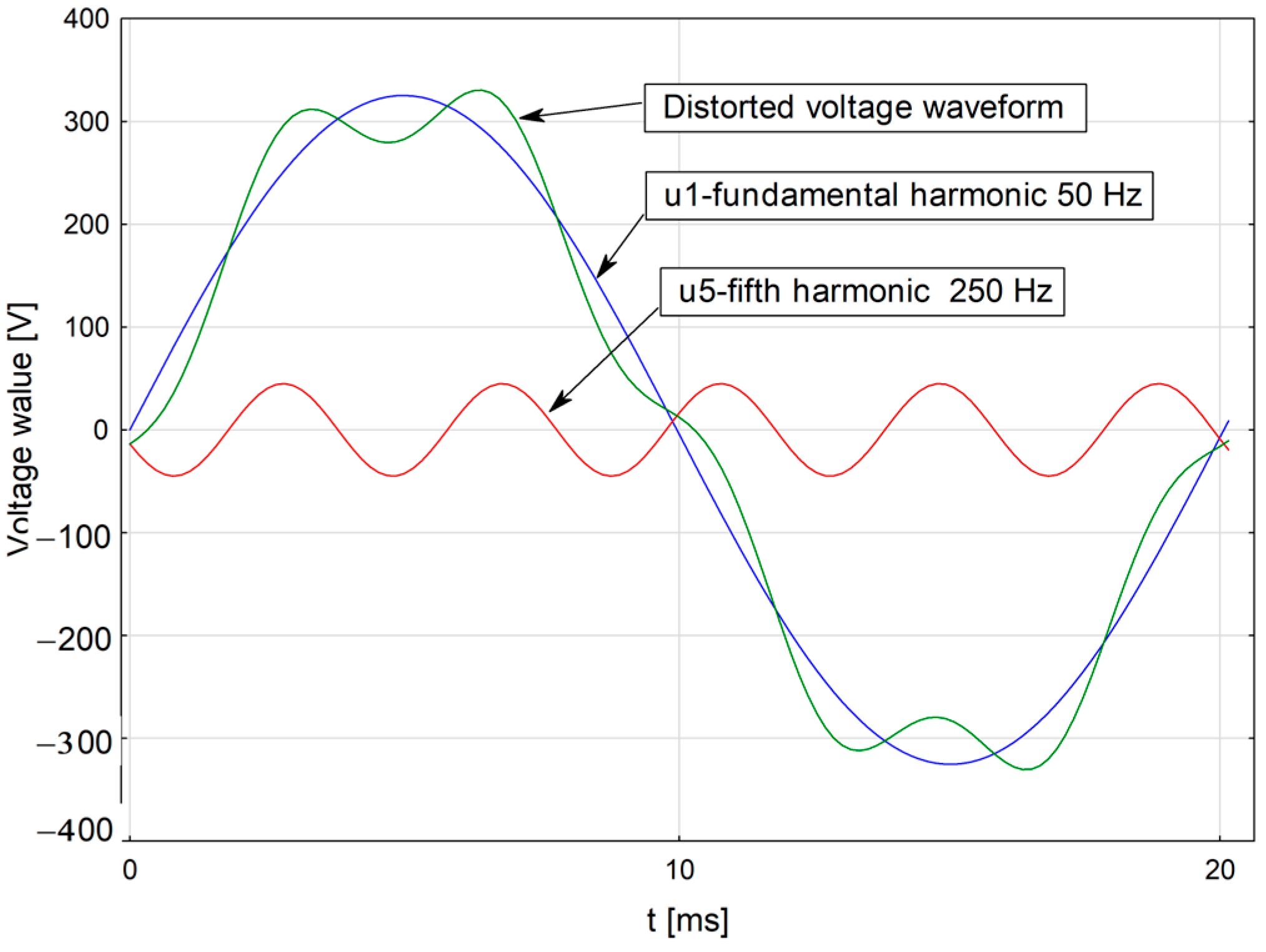
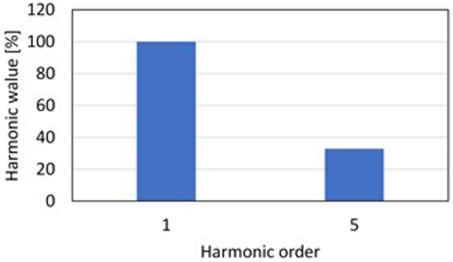
As can be seen from Figure 1 and Figure 2, higher harmonic current problems involve distorted voltage and current waveforms, i.e., non-sinusoidal waveforms. When analysing distorted (non-sinusoidal) waveforms, they are subjected to decomposition. A periodic distorted waveform can be represented as a superposition of sinusoidal waveforms that differ in amplitude, frequency, and phase angle. An example of the decomposition of a deformed voltage waveform in the time domain is shown in Figure 3. The distorted waveform is a superposition of the first harmonic at a frequency of 50 Hz and the fifth harmonic at a frequency of 250 Hz (these are sinusoidal waveforms). The frequency of the fifth harmonic is five times that of the first harmonic. Figure 3 shows only two harmonics, the first and the fifth, so the analysis of the deformed waveform and its harmonics is simple. However, with a larger number of harmonics, e.g., nine or even thirty-nine (harmonics with odd orders are most often analysed, e.g., 3, 5, 7, …, n), the analysis would be difficult and then Figure 3 would be illegible. It is therefore common to analyse distorted waveforms in the frequency domain by representing them as a frequency spectrum using the Fast Fourier Transform (FFT). Each harmonic is then represented as a single bar, so the distorted waveform shown in Figure 3 is represented by two harmonic bars, i.e., the first and fifth harmonics (Figure 4).
Modern instrumentation has built-in mathematical functions, including FFT, that allow the measured signal to be represented in the time or frequency domain. This includes oscilloscopes, power quality analysers, etc. These and other instruments are used to monitor the quality of the electricity delivered to the customer. The purpose of these measures is to ensure that the electricity supplied meets the relevant quality parameters.
Very often in the analysis of distorted waveforms, the coefficient of higher harmonic content THD (Total Harmonic Distortion) is used, defined as:
T H D = k = 2 n A k 2 A 1 · 100 %
where the following are defined: Ak—rms value of the k-th higher harmonic (k = 2, 3, …, n); A1—rms value of the basic (first) harmonic, n—the highest order harmonic that is taken into account in the THD calculation [8,9,10,23].
This coefficient determines the percentage of all harmonics with orders from k = 2 to n compared to the value of the first harmonic for a given distorted (non-sinusoidal) waveform under analysis.
Another parameter describing the quality of the supplied energy is the contribution factor of individual higher harmonics HD (Individual Harmonic Distortion), defined as [10]:
H D = A k A 1 · 100 %
Very often, based on this coefficient, the percentages of the contribution of individual harmonics are calculated, which, as shown in Equation (2), are related to the value of the first harmonic A1. The calculated percentages of individual harmonics are then presented in the form of bars on graphs, which makes it very easy to compare them with the value of the first harmonic, whose value is then 100%. This method of graphical presentation of higher harmonics is commonly used in publications in this field.
Current harmonics can negatively affect the operation of the power system and the loads in it [3,4,8,9,11,23]. The distorted current drawn by nonlinear loads causes, among other things, a distortion of the supply voltage, an increase in thermal losses in the conductors, additional load on the neutral conductor, accelerated ageing of the insulation, and the formation of additional dielectric losses.
The consequence of current and voltage distortion in an electrical circuit with non-linear loads is an increase in active power losses, excessive reactive power consumption, and distortion power. In the appendage of the transformers, higher current harmonics cause an increase in active power losses in the core and in the windings [8,9,10,24]. Transformers, especially those of older types, loaded with non-linear loads cannot be fully loaded. In the case of motors, as in transformers, harmonics generate additional power losses, insulation ageing is accelerated, machine vibration can occur, and its operation generates additional noise [8,9,10]. Capacitor batteries are particularly sensitive to current harmonics. They may experience accelerated ageing and short circuits in insulation, voltage, and current overload.

1.3. Motivation

Taking into account the dangers from higher current harmonics and the problems described in the Introduction of this paper, the following part of this paper shows an example of research on the generation of harmonics by an RGB LED lamp adapted to adjust the value of luminous flux and changes in light colour.
This paper is organised into four chapters. The second chapter provides information on the role of LED lamps in modern lighting systems and the power supply systems for such devices, with particular emphasis on the causes of higher harmonic current generation. The third chapter is a description of the tests carried out on the RGB LED lamp, together with an analysis of the obtained results. Chapter four concludes with an indication of future work.

2. Harmonics in LED Lamps

2.1. The Role of LED Lamps in Lighting Systems

Lighting receivers are used in industrial, commercial, and office buildings to illuminate interior spaces with artificial light. Depending on the needs, the lighting systems installed there can perform different functions; for example, in stores, it will be in addition to the implementation of the basic function, i.e., lighting of the general and working area (for example, to illuminate the cash registers), and there will also be a decorative and display function, whose task will be to accentuate the store goods on the shelves or in the display windows. Similarly, lighting systems used to illuminate open areas also have a primary lighting role, and in this case, it will be to illuminate traffic routes, but nowadays, it is very often used for decorative lighting of building facades, monuments, and other architectural objects, such as city fountains, bridges, etc. [25]. Examples of contemporary illuminated shopping malls and cities with architectural objects are presented in Figure 5 and Figure 6.
From the photo examples, it is clear that artificial light plays a significant role in the modern world. It is estimated that global lighting energy consumption accounts for about 20% of total global electricity consumption. By 2030, lighting consumption is expected to increase to 60% if no appropriate preventive measures are taken [26]. The use of LED light sources as a replacement for previously used incandescent, fluorescent, or discharge light sources has undoubtedly contributed to the rise in popularity of lighting. This has been made possible by the great technical and technological progress that has taken place over the past few years. The popularity of LED lamps has been determined, among other things, by their high luminous efficiency, which translates into the energy efficiency of these lamps, long service life, and easy cooperation with intelligent building systems, and in the case of using RGB LEDs, it has become possible to create any arrangement using light colours. These are the undoubted advantages of LED lamps, but on the other hand, it has to be taken into account that these are receivers that must be equipped with special electronic power supply systems. Their task is to provide appropriate (as required) power supply parameters for the semiconductor structures of LED lamps.

2.2. Power Supplies Used in LED Lamps vs. Current Harmonics

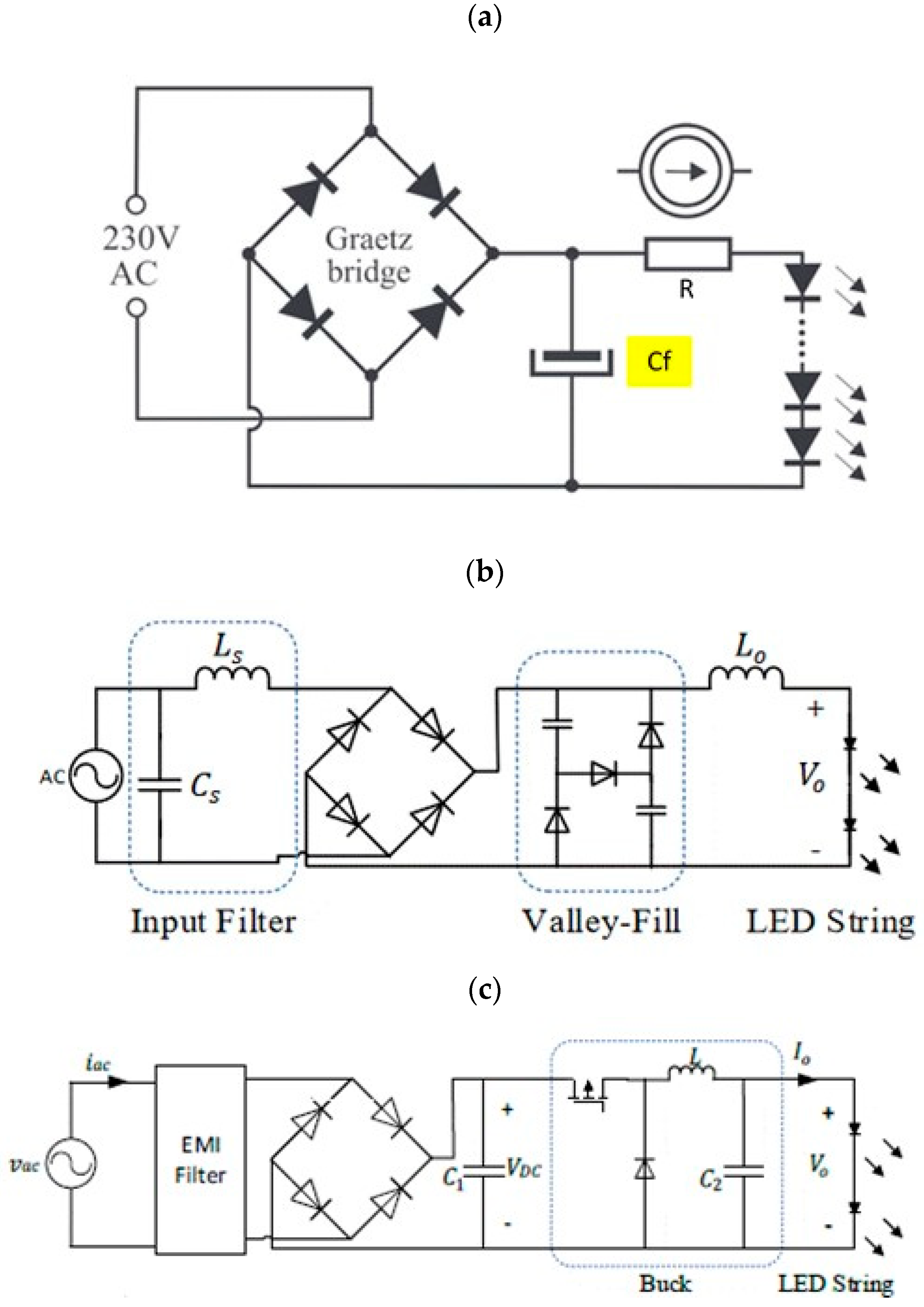
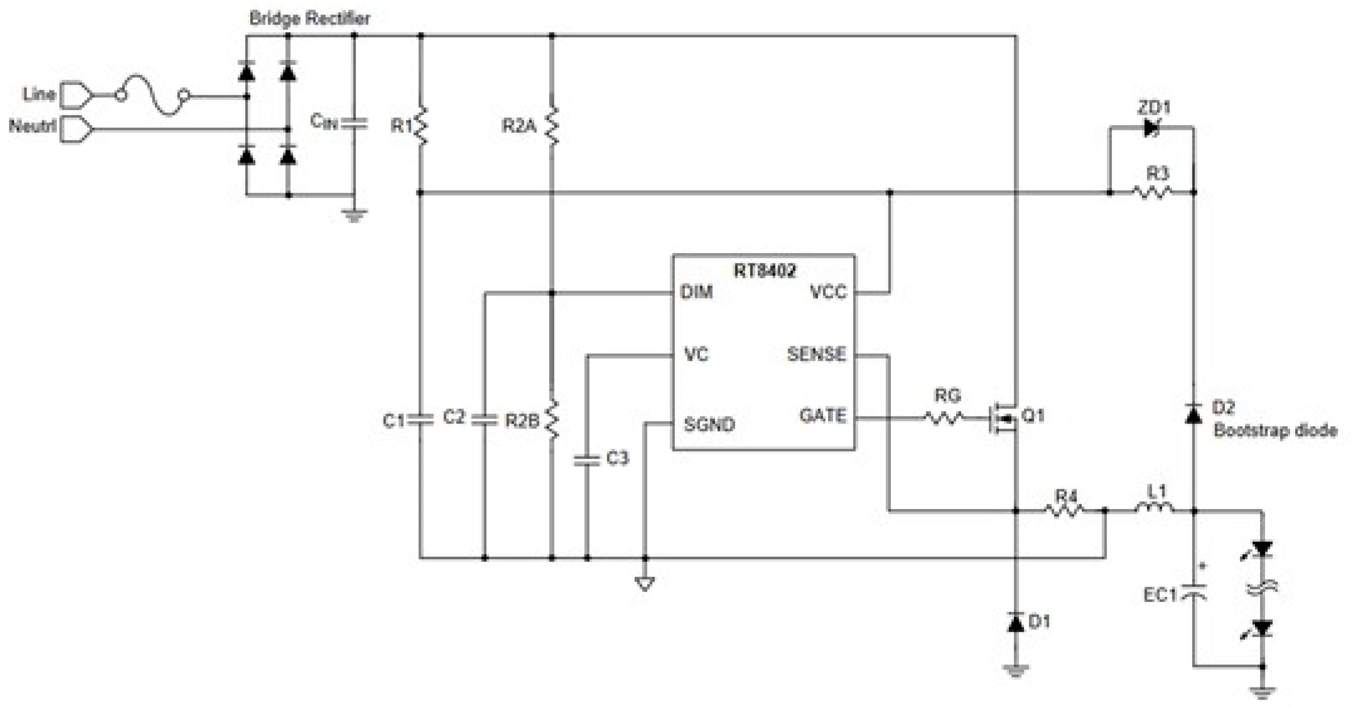
Various power supply systems are used to power LED semiconductor structures [26,27,28,29,30,31]. In the case of LEDs, one of the key factors that affect the life of the semiconductor structure is the value of the current. For this reason, every LED lamp power supply should be equipped with a current stabilisation circuit. Of course, the value of the voltage supplied to the matrix with distributed LED semiconductor structures is also important. In general, LED lamp power supplies can be divided into passive and active single- or multi-stage power supplies based on the circuit solutions and used components. Manufacturers use various circuit solutions for electronic power supplies in their LED lamps. Some selected examples, starting with the simplest passive ones (Figure 7), without current stabilisation with current-limiting resistor R, and ending with more advanced systems that use voltage converters (Figure 8 and Figure 9) are shown in Figure 7, Figure 8 and Figure 9. Of course, many other circuit solutions are used, being more or less complicated. For example, more complex power supplies are used to power RGB LEDs or monochromatic LEDs adapted to regulate the emitted luminous flux. The circuit solutions adopted for LED lamp power supplies also depend on the knowledge and awareness of designers, manufacturers, or importers, as well as the access to increasingly newer application and system solutions.
However, regardless of the solutions adopted, most power supply systems use a diode rectifier with a capacitor that filters the ripple of the rectified voltage at the input and then electronic modules to ensure current and voltage stability for the LED semiconductor structures that create the light matrix of the LED lamp, which, in the absence of an additional module in the form of a higher harmonic filter or a power factor correction circuit, causes the power supply to generate higher harmonic currents to the mains [9,28,29,32,33,34,35,36,37]. An LED lamp constructed in this way draws a distorted (non-sinusoidal) current and is seen as a nonlinear load from the mains. The accumulation of such receivers in, for example, commercial buildings, offices, or street lighting, can cause clusters of these lamps to generate harmonic currents of significant values into the power grid. And these, in turn, can adversely affect the supply voltage in the electrical network, causing its distortion, or adversely affect the correct operation of other devices installed in the network.
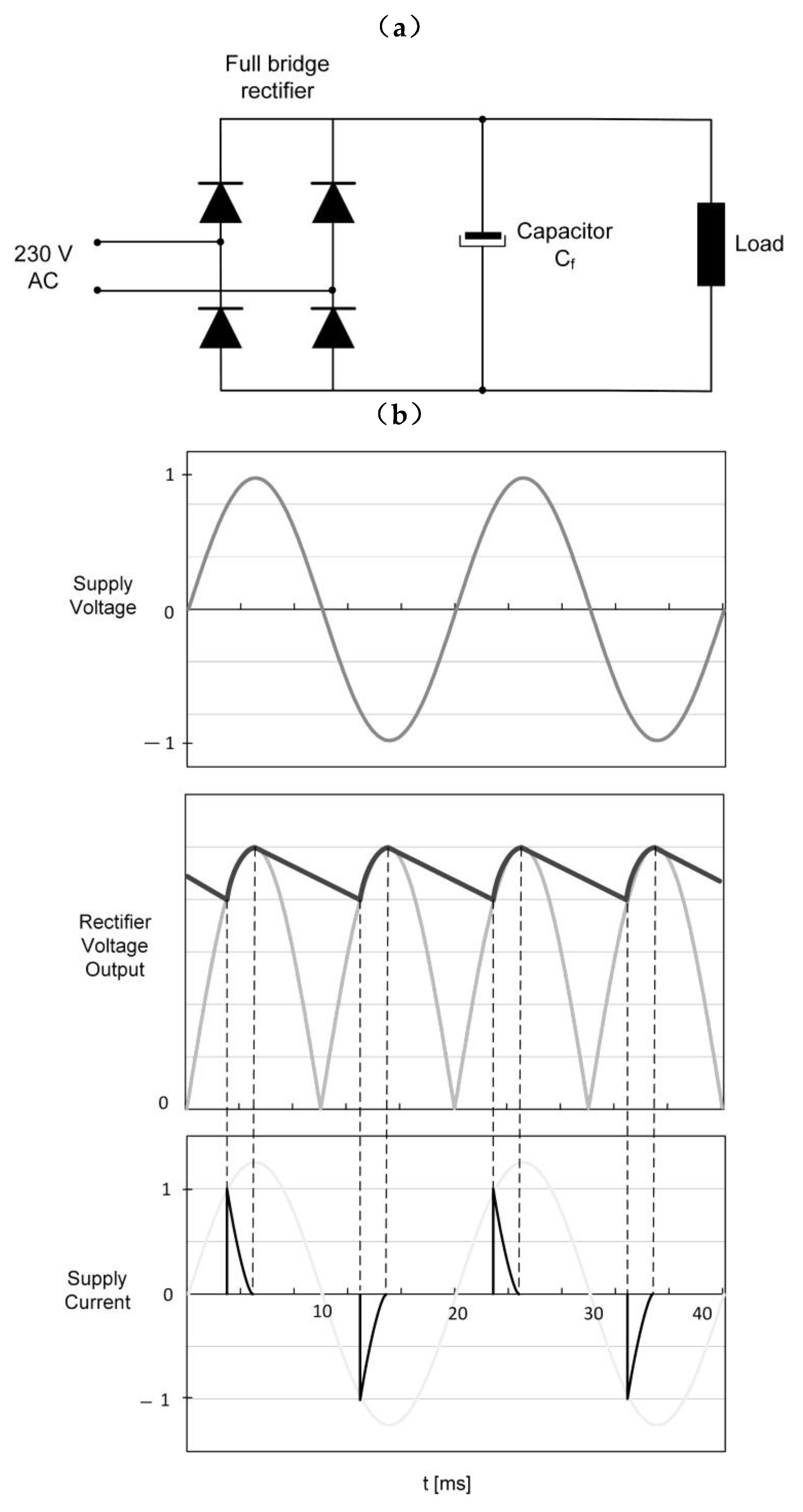
The power supply with a diode bridge rectifier, which lacks appropriate solutions to limit the emission of higher harmonics, is illustrated in Figure 10a.
Rectifiers of this type are often used in low-cost receivers, e.g., compact light sources, household appliances, etc. The current drawn by this rectifier has an impulse shape and is characterised by high nonlinearity, which has to do with the operation of a capacitor that smooths the voltage ripple at the output of the rectifier (Figure 10b). This current shape is a source of higher current harmonics [9,10,23,24,38].
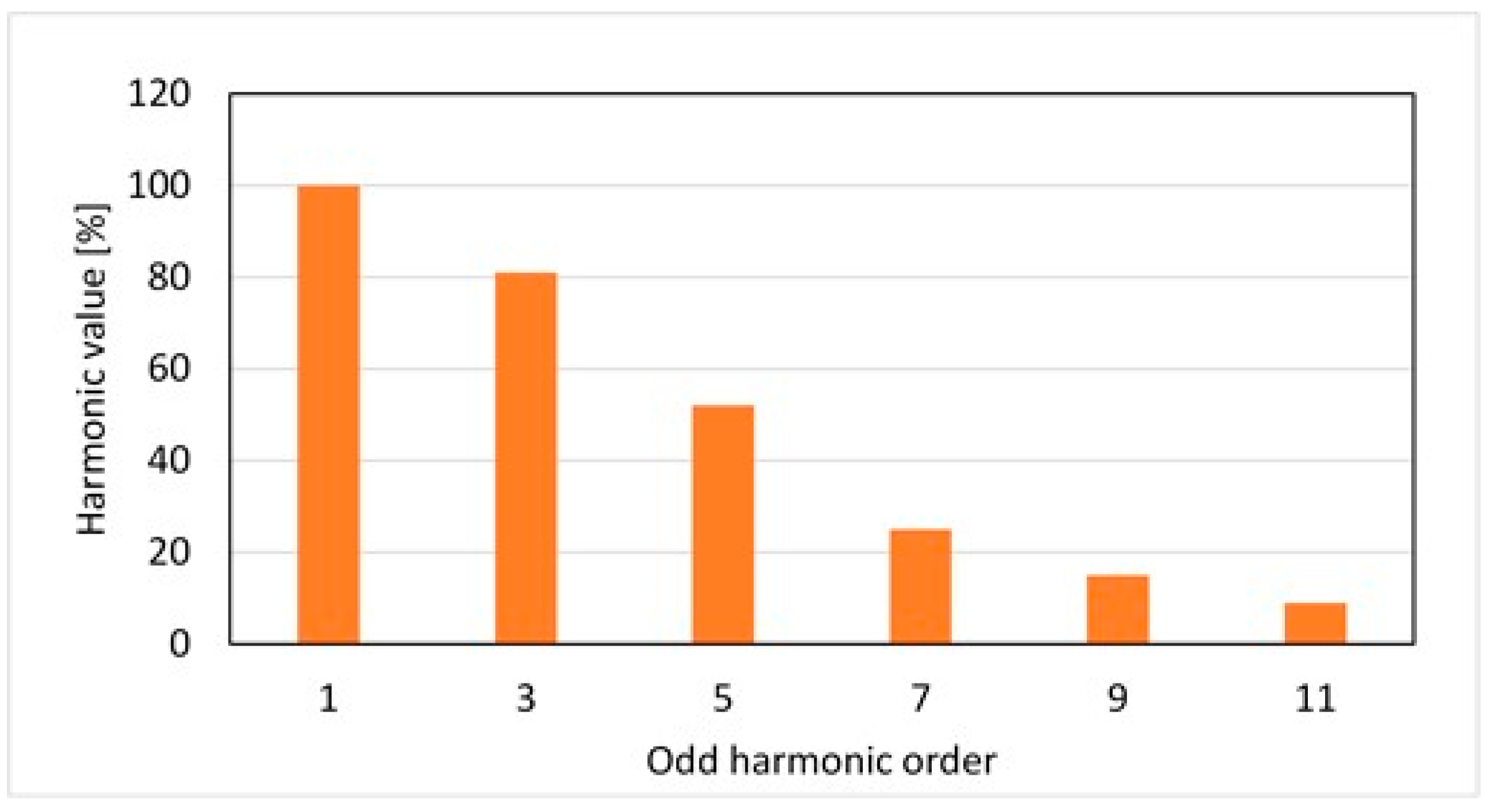
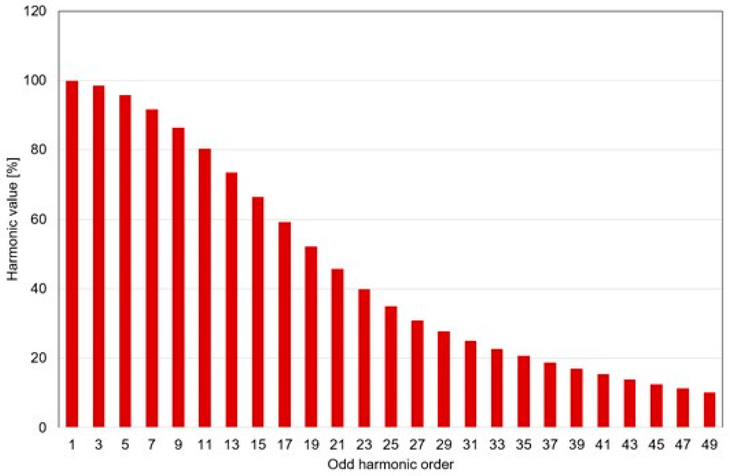
The odd harmonic spectrum of the current drawn by a full-wave rectifier with a filter capacitor Cf is shown in Figure 11.
The dominant harmonics are the odd harmonics and, as can be seen, their amplitudes decrease as the order of successive harmonics increases. Therefore, in comparative analyses, sometimes only the first few harmonics with significant values are considered.

3. Research of the Content of Higher Harmonics Generated by the RGB LED Lamp

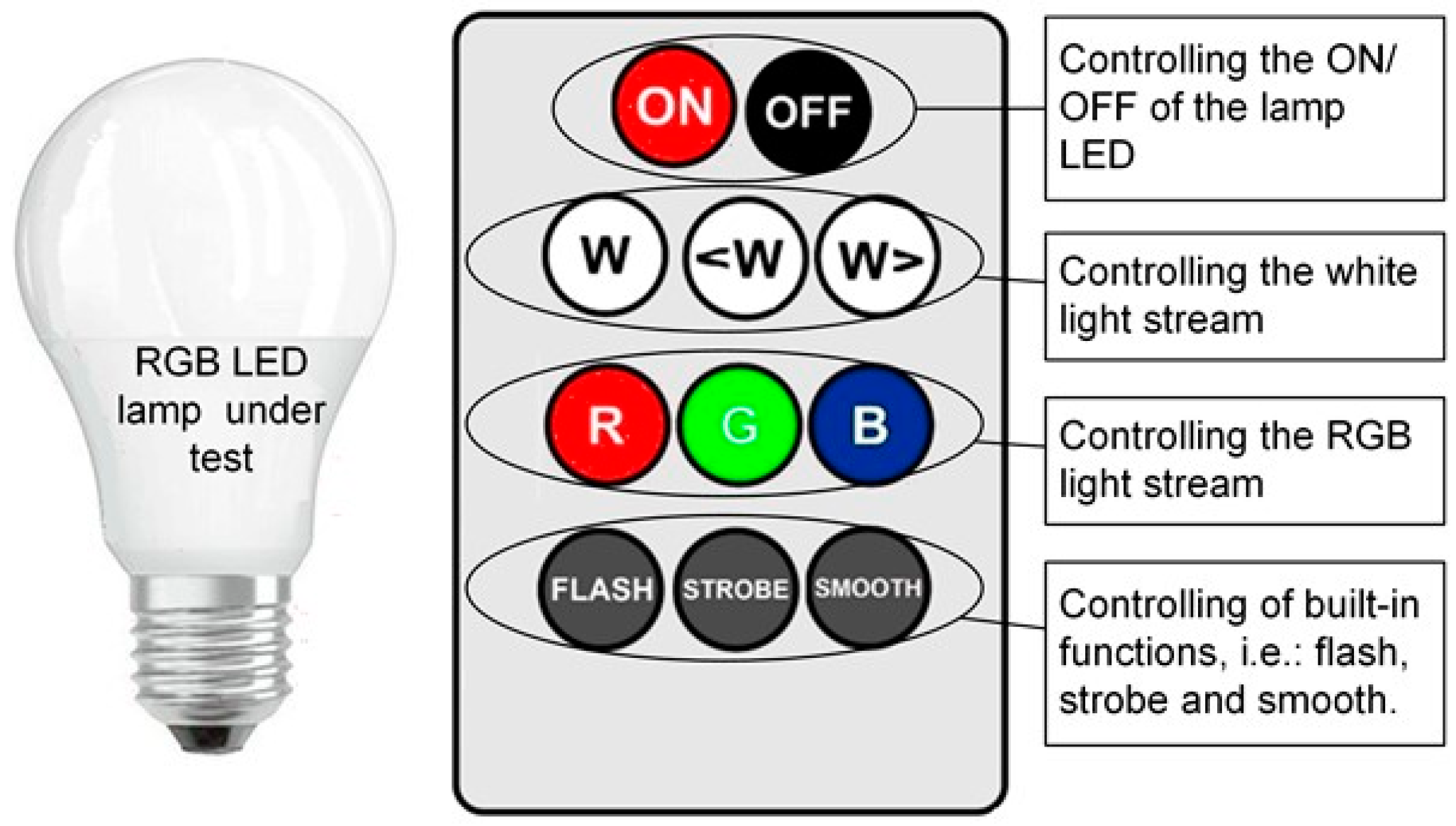
The RGB LED lamp was tested for its higher harmonic current content (Figure 12). It is an integrated lamp containing a matrix with LED light sources and an advanced electronic power supply in a single housing.
The power supply cooperated with an electronic external remote control, which allowed remote control of the lamp’s built-in functions. With it, it was possible to remotely turn the lamp on and off, change the colour of emitted light, change the value of white light output and colour light output, and turn on and off functions such as Flash, Strobe, and Smooth. On the remote control (Figure 12), only those buttons that were used during the tests carried out are marked. These will be on/off buttons, white light on and control buttons, buttons to change the colour of the emitted light, and buttons to select and activate built-in functions.

3.1. Research Methodology

The purpose of the investigation was to determine the values of individual current harmonics generated by the LED RGB lamp in its various operating states and to relate the values obtained to the parameters and shape of the current flowing through the lamp. Since the LED RGB lamp allows for arbitrary control of the value of the luminous flux and its colour, and has built-in functions, the research was carried out in several stages. First, the parameters of the current and its harmonic spectrum were determined when the luminous flux value of the white light was changed. Then, the same tests were carried out by making changes in the colour of the light, that is, turning on first the red-light flux, then the green, and finally the blue. At this stage of testing, the lamp emitted a light flux of a given colour at maximum settings (the value of light flux was not adjusted). In the next stage of testing, the harmonic spectrum and the parameters of the consumed current were determined when individual built-in functions, i.e., Flash, Strobe, and Smooth, were activated in the lamp. The tested LED lamp performing the mentioned built-in functions emitted light of different colours, from warm colours (red, orange) to cold colours (green and blue). The rate of light colour changes varied and depended on the function being performed; e.g., during the execution of the flash function, the period of a full cycle of colour change is 23 s, whereas for the strobe function, it is only 4 s. In the next stage of testing, changes were made to the power supply of the LED lamp under test. The original factory voltage ripple filter capacitor located behind the rectifier bridge was replaced with capacitors of different values. This stage of testing made it possible to determine the effect of changes in the capacitor value on the parameters of the current flowing through the lamp, and thus on the values of individual higher harmonics of the current.

3.2. Test Stand

The tests were carried out at the Electromagnetic Compatibility Laboratory of the Rzeszow University of Technology. The main components of the test stand, which include a programmable single-phase NetWave power supply from EMtest (Reinach, Switzerland), a PQM-711 power quality analyser from Sonel (Świdnica, Poland), and computer sets for control and data acquisition, are presented in Figure 13.
The wiring diagram between the components of the test stand is illustrated in Figure 14.

3.3. Test Results for the RGB LED Lamp

3.3.1. Change in the Luminous Flux Value of White Light

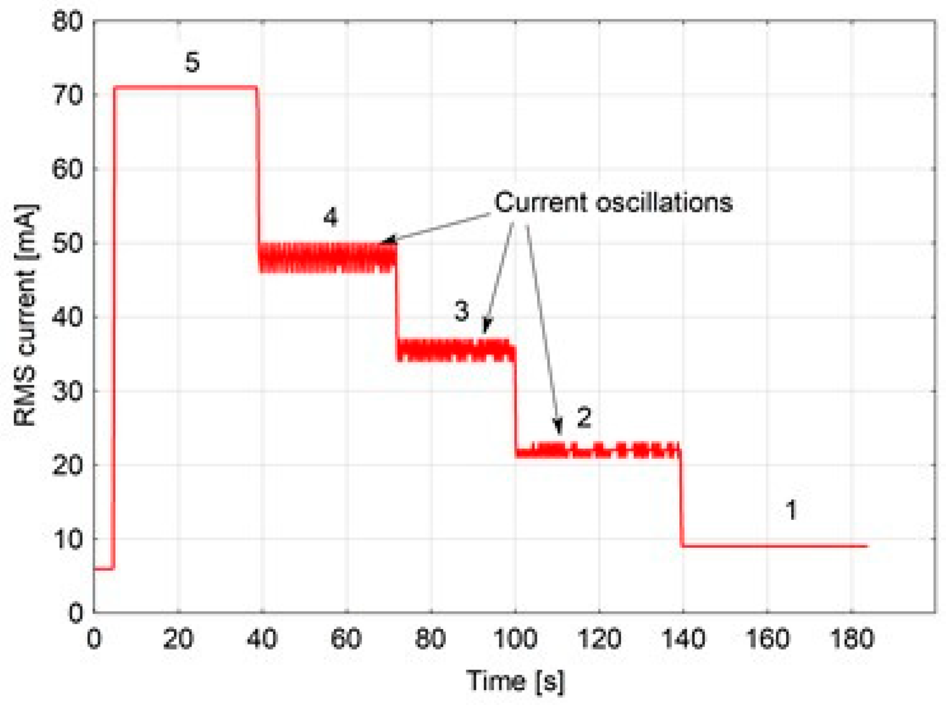
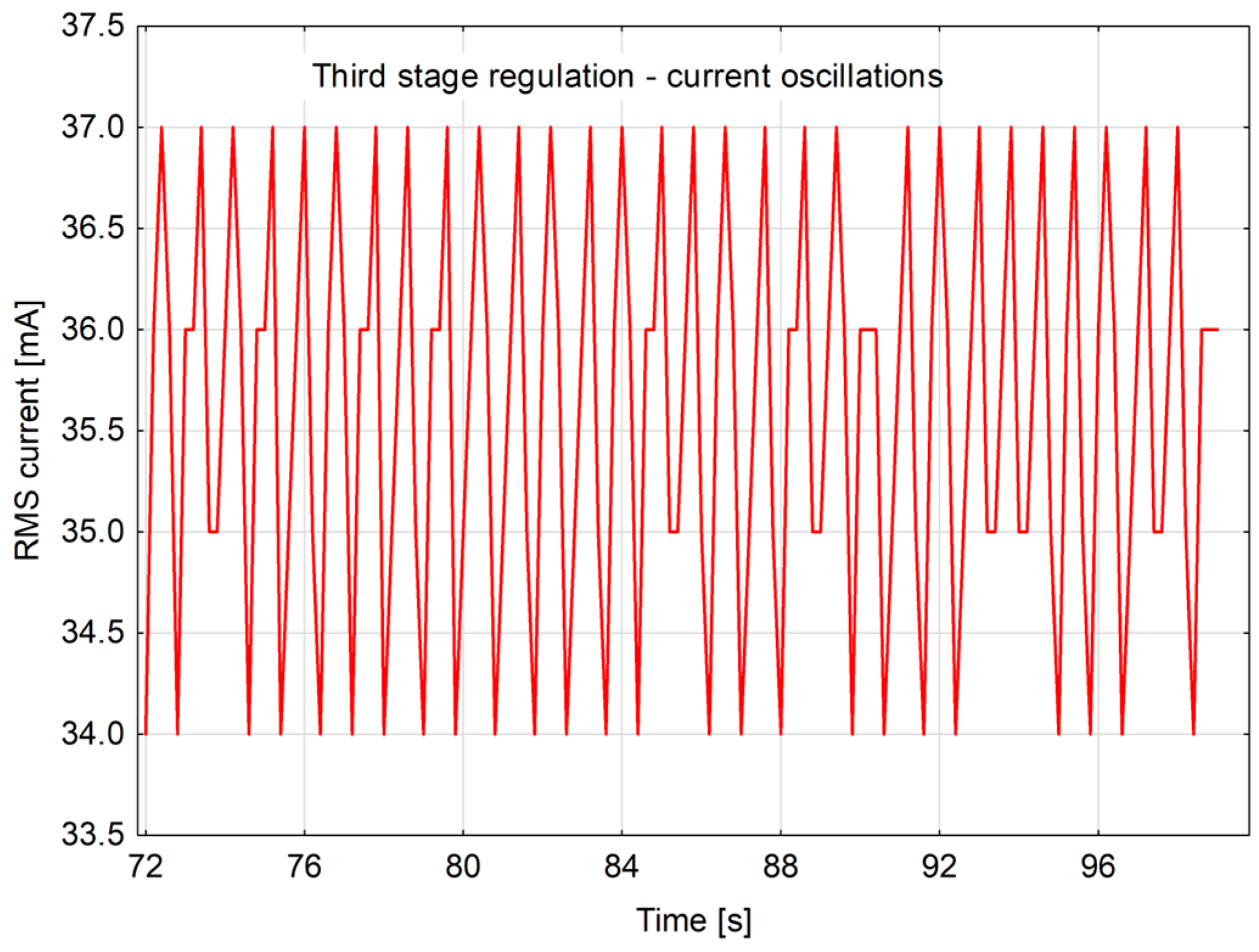
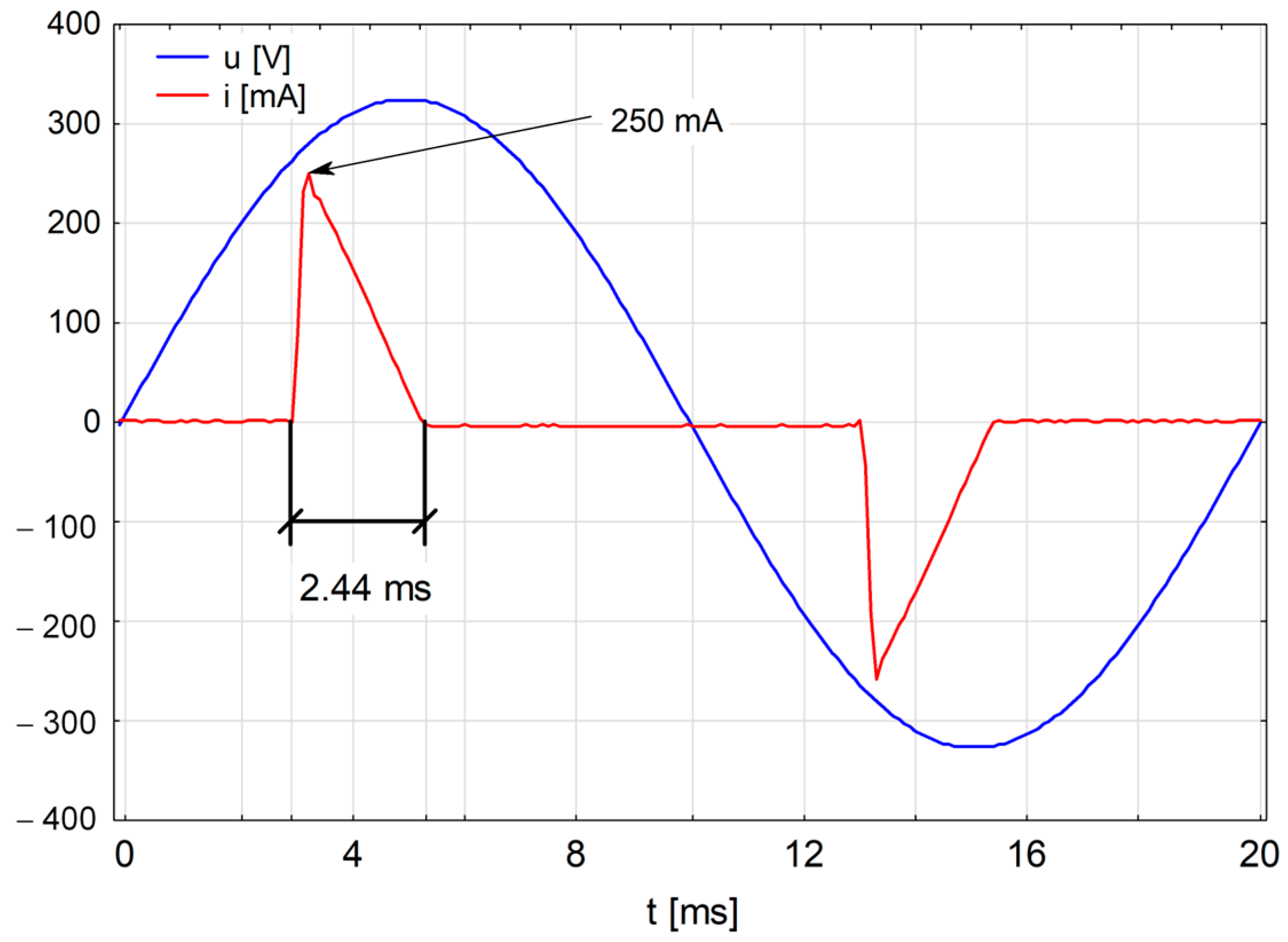
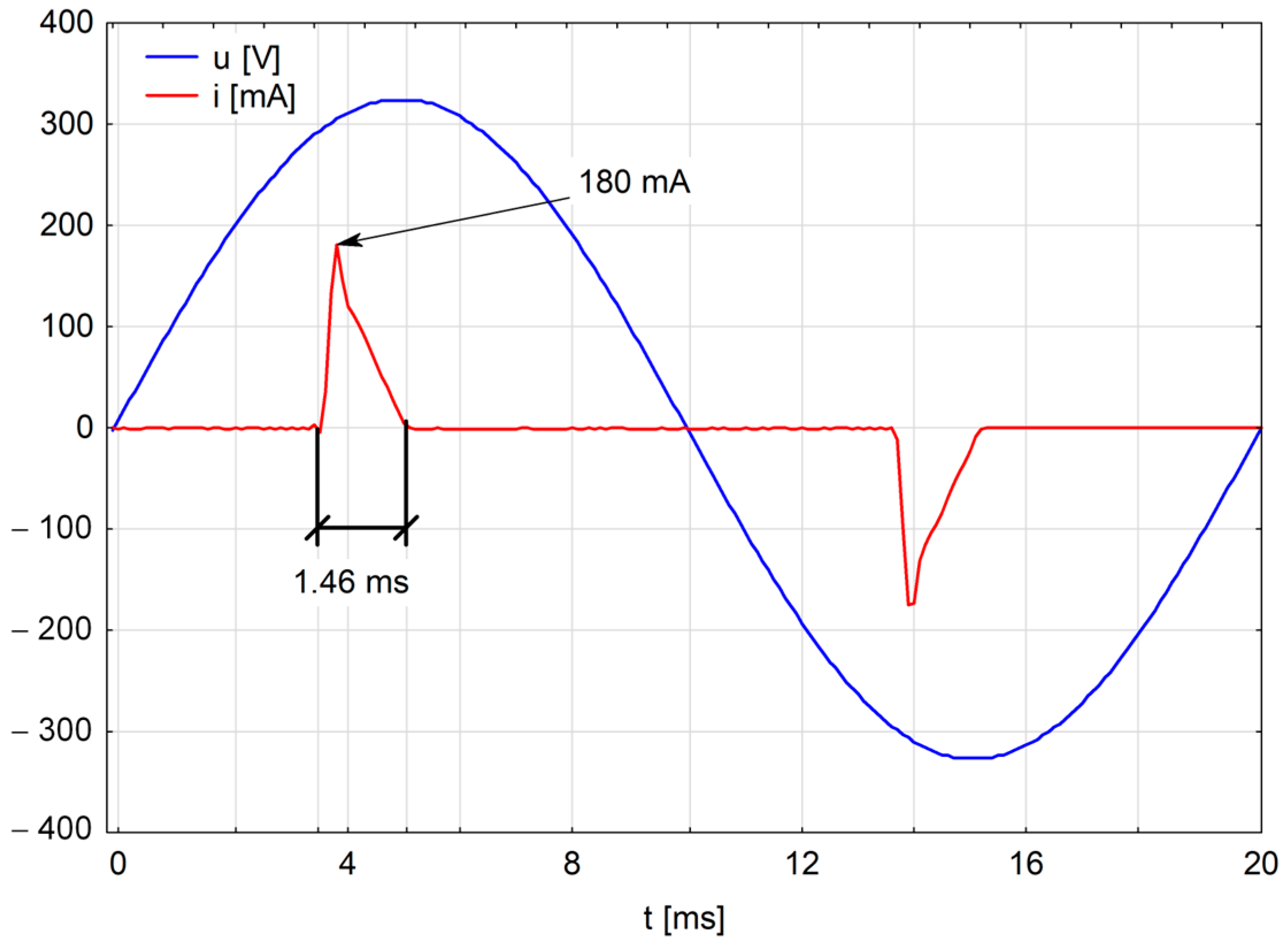
In the case of the analysed lamp, it was possible to adjust the value of white-light flux in five stages. A graph of changes in the rms value of the current flow during changes in luminous flux is shown in Figure 15. The light flux was gradually adjusted from the maximum value (5) to the minimum value (1). The value of the current drawn at each step decreased. In the lower stages of regulation (from 4 to 2), oscillations appeared; for example, in stage 3 the current oscillation has a value of ΔIpp = 3 mA (Figure 16). The current flowing through the lamp is pulsed in nature with a steep rise. The oscillograms of the current flowing through the lamp on control stages 5 and 3 are presented in Figure 17 and Figure 18, respectively. The duration of a single current pulse is very short. For example, in stage 5, it was t = 2.44 ms, and the amplitude reached im = 250 mA (the rms value of the current drawn in this stage was about I = 72 mA). In comparison, a further reduction in the duration of the current pulse, which lasts 1.46 ms, takes place at control stage 3. There is also a reduction in the value of the current amplitude, which is 180 mA (the rms value of the current flowing in this stage was about I = 35 mA). The short-duration pulsed shape of the current flowing through the lamp at the various control stages causes the generation of higher current harmonics.
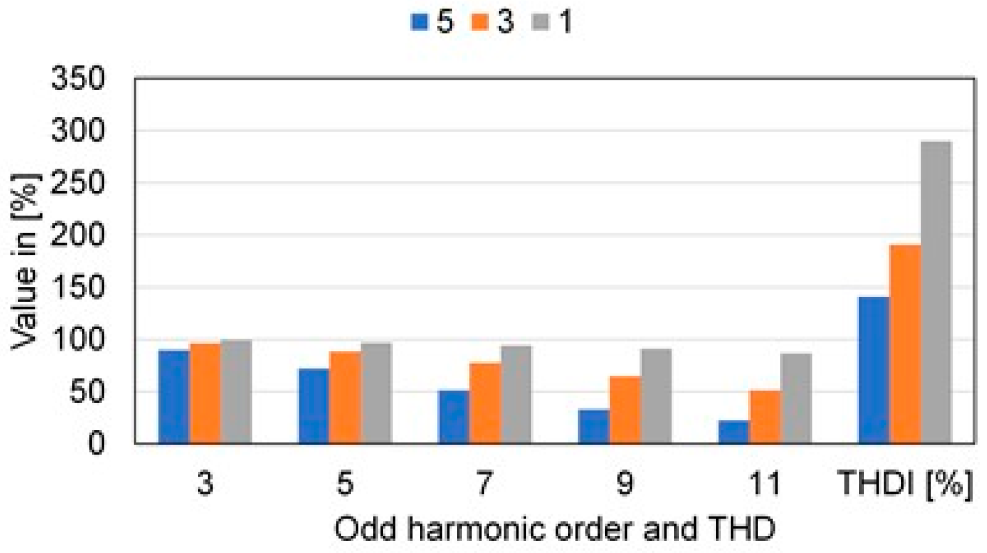
The pulsed nature of the current results in the RGB LED lamp generating higher current harmonics. The values of the dominant odd current harmonics generated by the lamp in the 1st, 3rd, and 5th control stages are listed in Table 2. The given values of higher harmonics have been related to the value of the first harmonic and are expressed as a percentage according to Equation (2). As can be seen, decreasing the value of the luminous flux (from stage 5 to 1) causes an increase in the values of individual harmonics. The greatest increases take place for harmonics 9 and 11. An increase in the odd harmonics of the current, when the luminous flux is reduced, results in a significant increase in the THD coefficient of the current (expressed in Equation (1)). The duration of the current pulse flowing by the LED lamp under test also decreases. Analysing the results in Table 2, it can be concluded that the increase in the values of individual harmonics and the THD coefficient depend not only on the value but also on the duration of the current pulse in the LED lamp.
The dominant current harmonics for the case of adjusting the white-light flux value at control stages 5, 3, and 1 are presented in Figure 19. It can be seen that a reduction in the value of the luminous flux causes an increase in the value of the generated current harmonics and thus an increase in the THD value. One factor that causes an increase in the values of the individual harmonics is a reduction in the duration of the current pulse (Figure 17 and Figure 18). A particularly large change is evident for harmonics 9 and 11.
The increase in current THD is shown in Figure 20. At the maximum luminous flux value (fifth degree of control), the value of the THD coefficient was 140.69%, while on the third degree, its value increased by 50.06% and reached 190.75%. On the other hand, in stage 1 (minimum light output value), the coefficient value increased to 289.78%, i.e., by 99.03% compared to stage 3 and by 149.09% compared to stage 5. The relative increase in the value of the THD coefficient with respect to the value of 140.69% (THD value at stage 5) was 35.58% for stage 3 and 105.97%, for the stage 1 respectively.

3.3.2. Changing the Colour of RGB Light

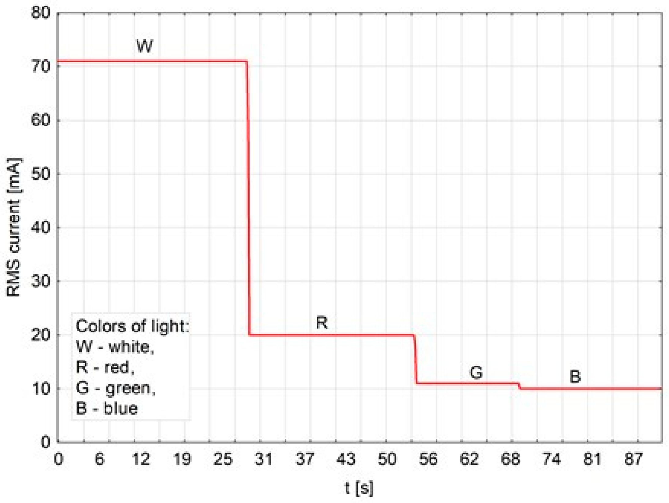
RGB LED lamps allow us not only to change the luminous flux, but also to choose any colour of the emitted light. This possibility is provided by an advanced controller installed in the lamp, which allows one to appropriately select the proportion of each primary colour, i.e., red (R), green (G), and blue (B), and thus obtain any colour of light emitted by the lamp. Therefore, in this part of the study, the colour of the light emitted by the lamp was changed and the values of the generated current harmonics were determined for each of them. The recorded changes in the rms value of the current drawn when the lamp emitted successively switched colours of light R, G, and B are shown in Figure 21. As can be seen, the current values gradually (stepwise) decrease starting from the highest value of about 72 mA drawn when the lamp emitted white light (W) through the subsequent red (R) and green (G) colours and ending with the blue (B) colour where the lamp drew a current of about 10 mA. An example oscillogram of the current drawn by the lamp when the LED lamp emitted red (R) light is shown in Figure 22.
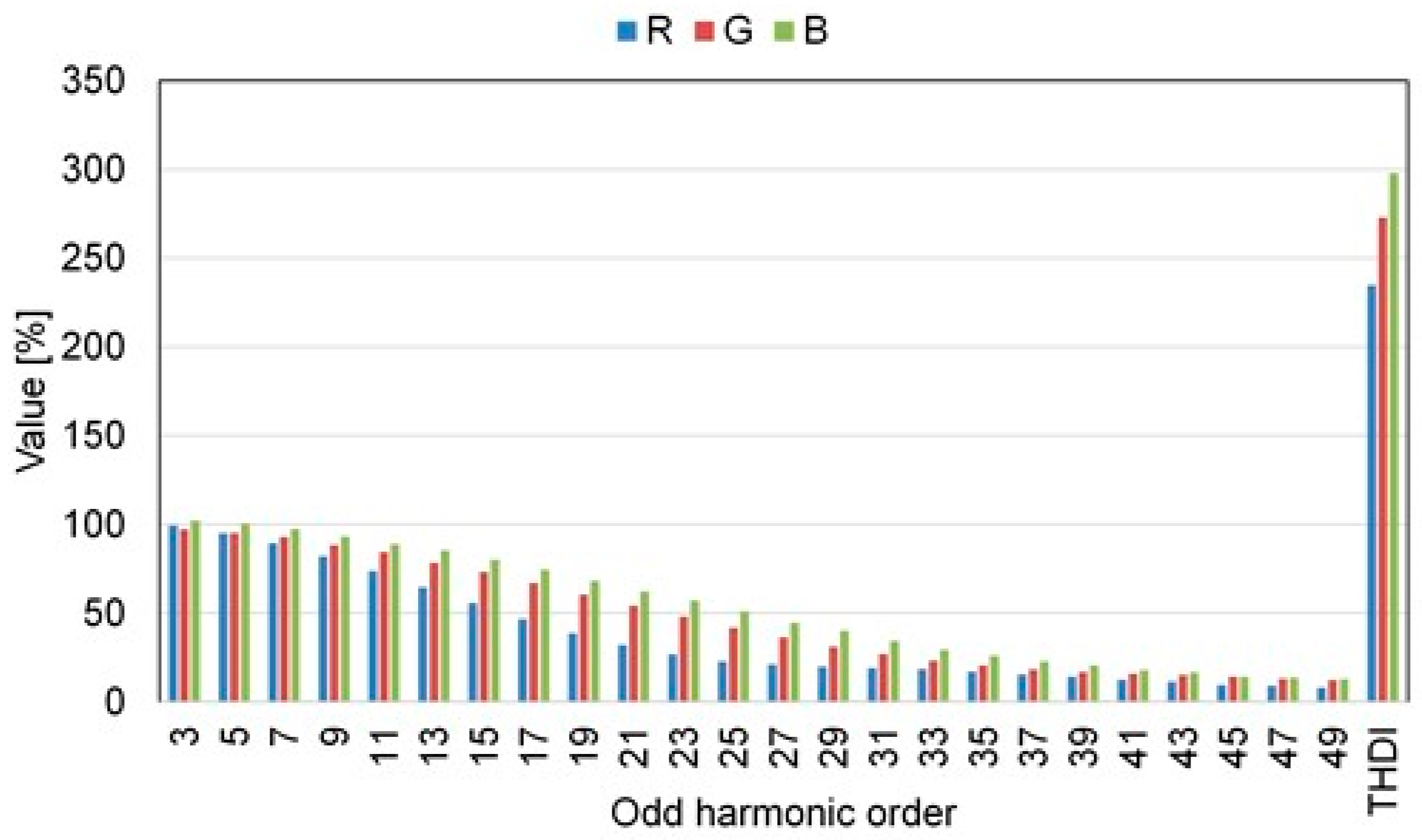
The shape of the current in this case is also pulsed. For the emitted red light colour (R), the pulse duration is 1.17 ms and its amplitude has a value of 101 mA; for the green light colour (G), the current pulse lasted 0.88 ms and had a value of 63 mA; and for the blue colour (B), the current pulse lasted 0.87 ms and had a value of 53 mA. The change in the value of the duration of the current pulse is reflected in the value of the current harmonics generated, which, for the different colours emitted by the lamp, are shown in Table 3.
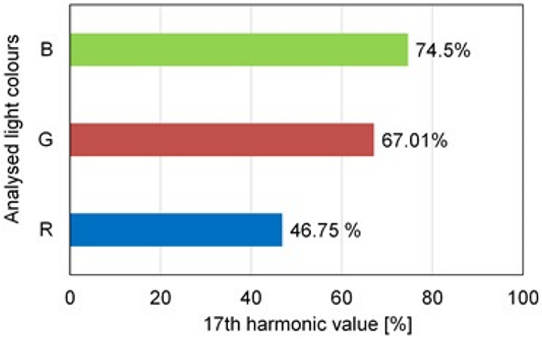
Analysing the current pulse durations (Table 3), it can be seen that the current pulse taken by the lamp that shone with red light (R) had the longest duration of 1.17 ms, while for the other colours green (G) and blue (B), the pulse durations are comparable at 0.88 ms and 0.87 ms, respectively. A summary of the current harmonics and THD values is presented in Figure 23. It should be noted that the effect of the current pulse duration on the harmonic value is particularly evident for harmonics of the 13th to 27th order. For example, harmonic 17 has a value of 46.75% for a current pulse lasting 1.17 ms, while the same harmonic for current pulses with durations of 0.88 ms and 0.87 ms reaches a value of 67.01% and 74.5%, respectively. This example clearly shows that the duration of the current pulse is one of the factors influencing the value of the current harmonics and the THD value. A summary of the changes in the value of the 17th harmonic current for the three light colours analysed (R, G, and B) correlated with the duration of the current pulses is shown in Figure 24.

3.3.3. Built-In Functions (Flash, Strobe, Smooth) vs. Values of Generated Harmonics

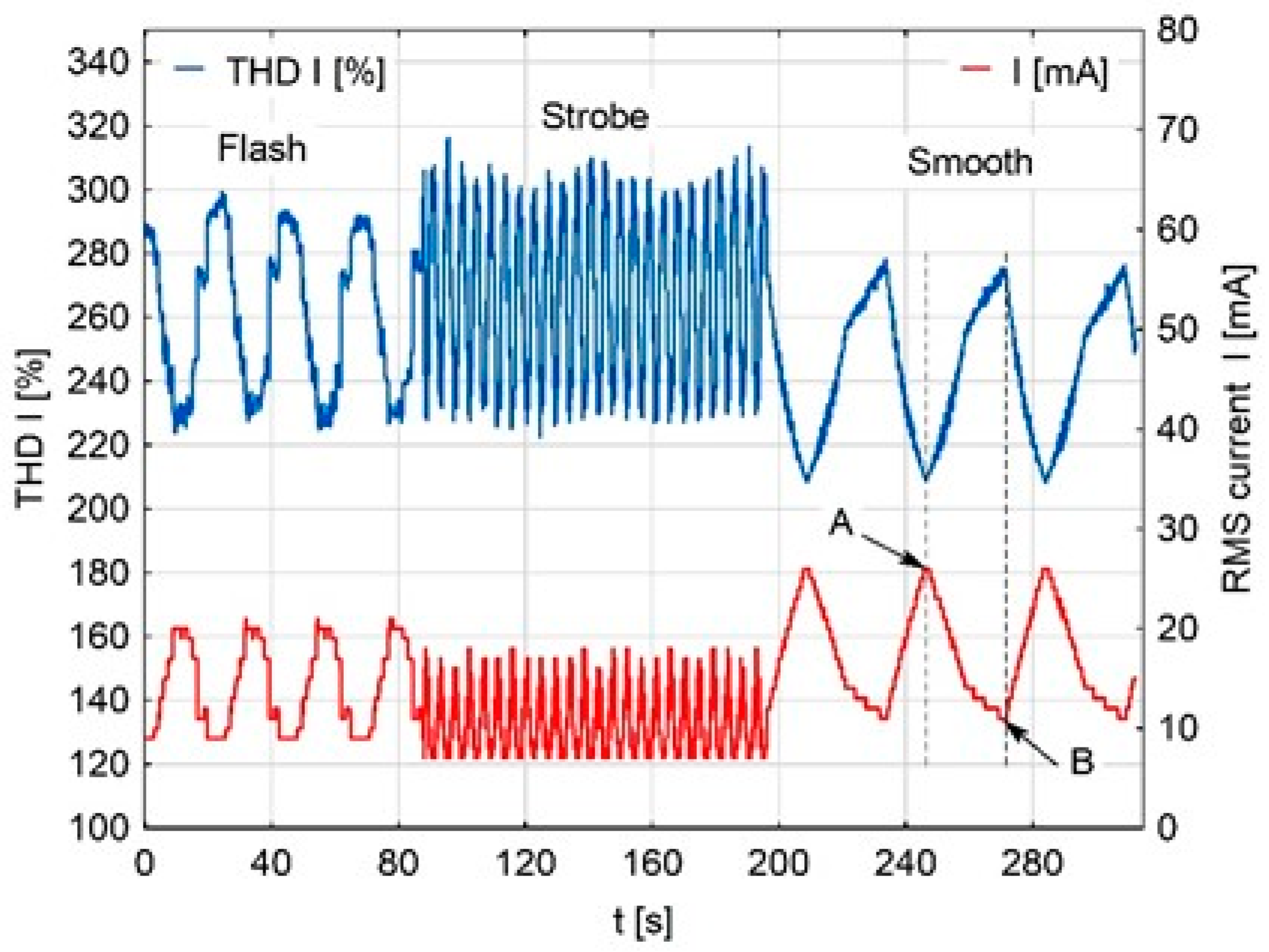
The tested RGB LED lamp had built-in ready-made functions to automatically change the colour and value of the emitted luminous flux. The recorded changes in the rms value of the current for each built-in function are presented in Figure 25. As can be seen, the flash function realises light colour changes in a stepwise manner. The strobe function automatically generates cycles of light flashes of very short duration, and the smooth function is characterised by very slow lamp illumination combined with changes in light colour. Warm colours of emitted light are associated with higher current consumption compared to the current consumed by the lamp when cool colours were emitted.
For example, the LED lamp analysed, while performing the Smooth function, provided light that changed gradually in a slower way compared to the changes in light colour during the Strobe function. When the Smooth function was implemented, the light changed its hue from warm tones (red tones) to cold tones (blue tones) to switch to warm tones again. These cycles of change were repeated. As can be seen in Figure 25, at point A, when the lamp provided light in warm hues, the rms value of the current drawn was the highest, at 26 mA, and its distortion value, determined by the THD coefficient, was 209.03%. The large value of the THD coefficient is the result of significant values of odd harmonics of the current. Then, the light colour changes to a warm to cold colour (point B), then the value of the drawn current decreases to a value of 11 mA and the value of the THD coefficient increases even more, which reaches a value of 275.32% causing an increase in the values of the individual harmonics of the current. A summary of the rms values of the current (RMS I), selected harmonics, and the THDI factor of the current for the points A and B analysed is given in Table 4.
The harmonic current values generated by the RGB LED lamp during the execution of the built-in functions mentioned above were also analysed. For example, the spectrum of current harmonics generated by the tested lamp during the implementation of the Flash function is presented in Figure 26. Changing the value and colour of the emitted luminous flux causes changes in the value of the current drawn (Figure 21) and changes in the values of the generated harmonics. Therefore, the values of current harmonics (Figure 22) are calculated averages from the average values of current harmonics measured in successive 200 ms measurement windows during the Flash function.
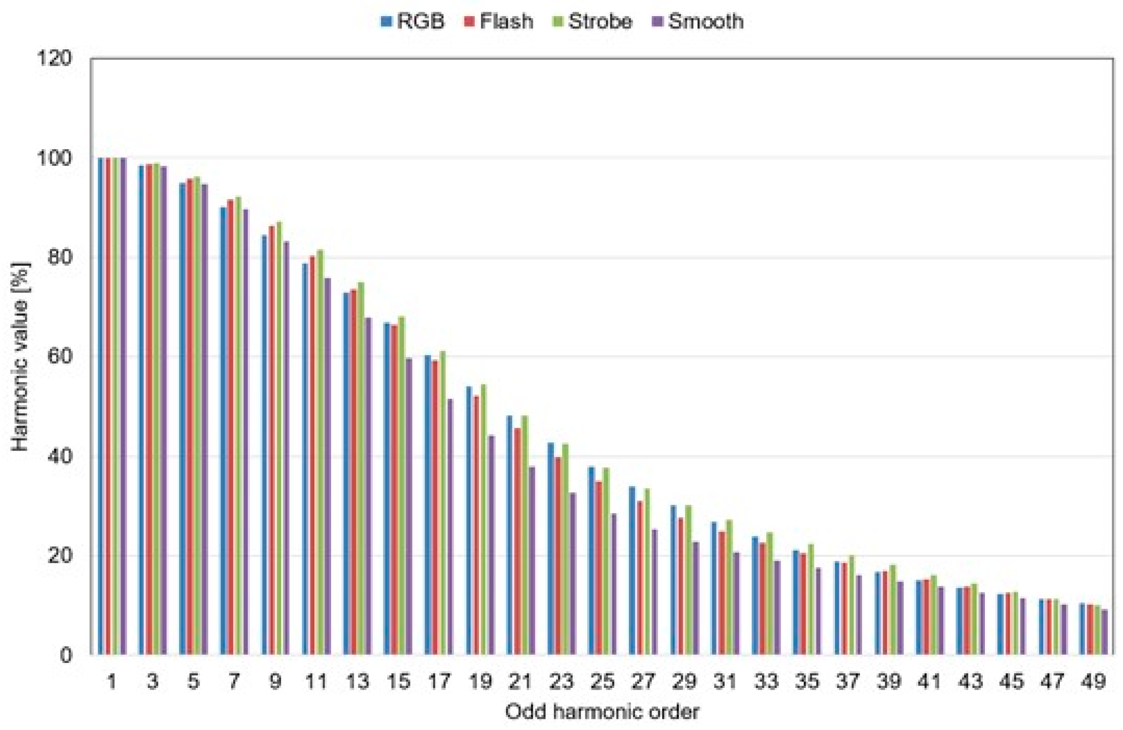
Similarly, harmonic current values were calculated for the operation of the LED lamp during the execution of the Strobe and Smooth functions, as well as during changes in the colour of the RGB luminous flux. The results obtained for each harmonic are shown in Figure 27.
As can be seen from Figure 18, the lamp operates ‘the best way’ with the Smooth function enabled, followed by Flash and RGB, while it performs unfavourably when it implements the Strobe function. During the implementation of the built-in functions (RGB, Smooth, Strobe, and Smooth), the lamp contains harmonics in its spectrum, which have significant values even close to the value of the first harmonic of the current, which is reflected in the calculated THD values of the current.

3.3.4. The Effect of Changes in the Value of the Filter Capacitor in the Power Supply

Chapter two describes example power supply systems for LED lamps and shows the effect of a rectifying bridge and a smoothing capacitor Cf on the distortion of the current drawn by the LED lamp and thus on the generation of higher harmonics. For the emission of low-frequency disturbances associated with higher harmonics, the solutions that are used in the power supply of the LED lamp play a decisive role. These can include the use of higher harmonic filters, a PFC power factor corrector, or the appropriate selection of a capacitor to smooth the voltage ripple behind the rectifier bridge. Very often in low-budget LED lamps in electronic power supplies, manufacturers omit the use of appropriate filters to limit the emission of higher harmonics of the current, either for design reasons or due to the limited space in the lamp stem. The RGB LED lamp under test also does not use a higher harmonic filter.
The block diagram of the lamp under test is shown in Figure 28. It can be seen that the DC rectified voltage feeds two converters via identical Cf capacitors of 2.2 µF. Converter 1 supplies a chain of white-light emitting diodes (LED W), while converter 2 is responsible for a chain of RGB LEDs. To investigate the effect of variations in current pulse width on the value of higher harmonics emitted, the values of the smoothing capacitors Cf located in the circuits of converter 1 and converter 2 were swapped.
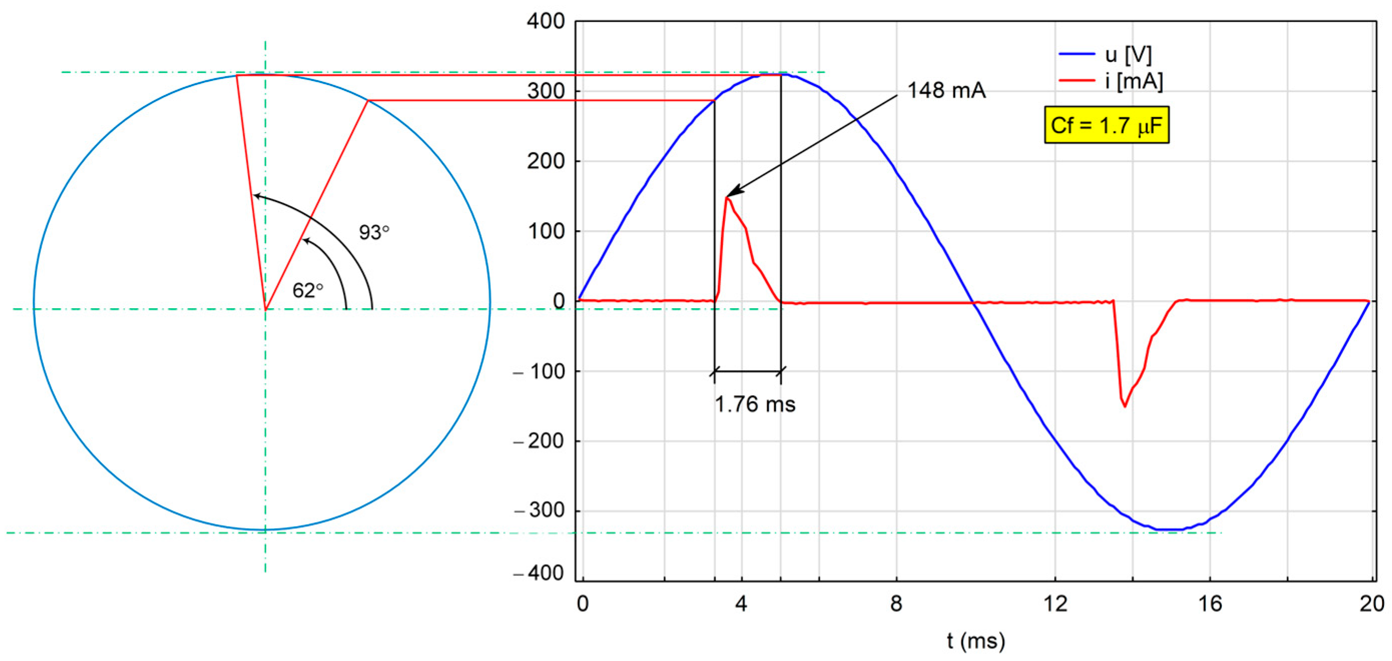
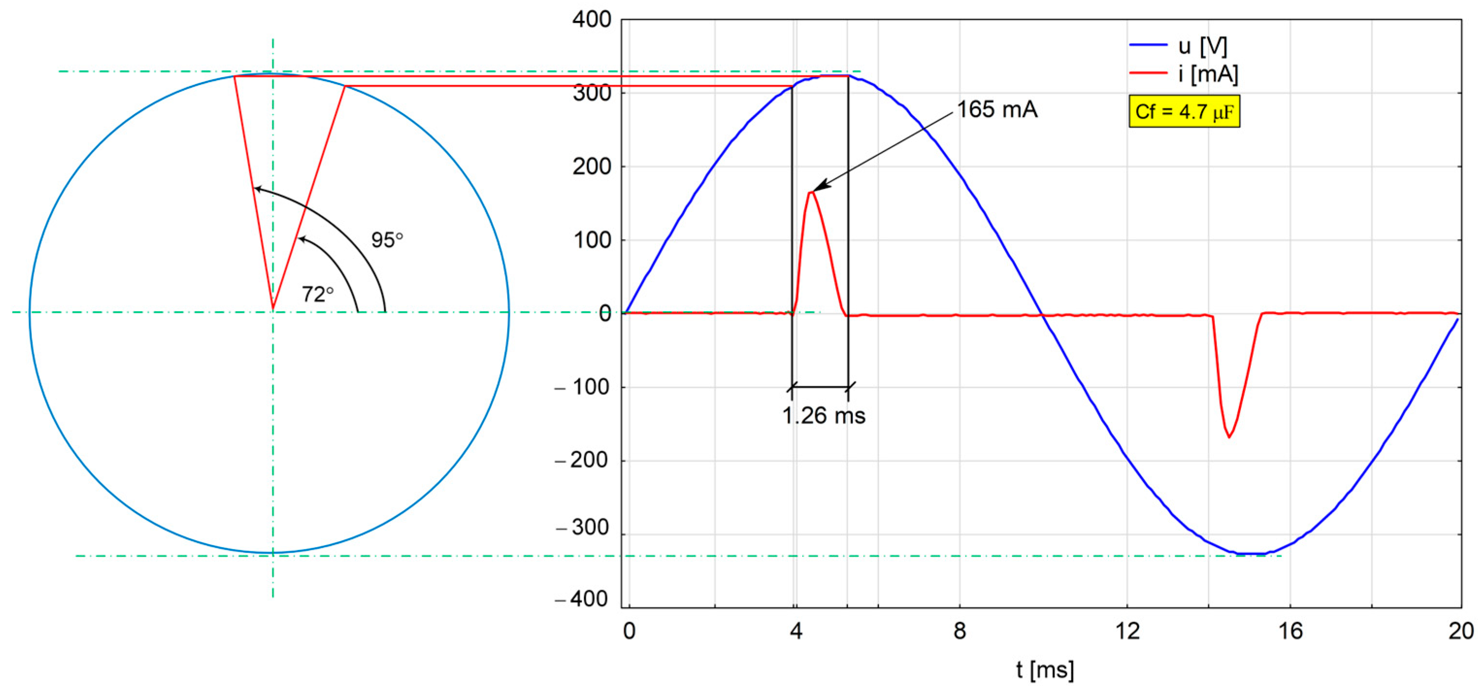
In the tested RGB LED lamp, a 2.2 µF smoothing capacitor is installed behind the rectifier bridge at the factory. This capacitor was replaced by a 4.7 µF capacitor and the operation of the lamp modified in this way was analysed with regard to the shape and duration of the current pulse and the odd harmonics generated. The tests were repeated by installing a 1.7 µF capacitor in place of the previous one (which is the resultant capacitance of series connected capacitors of capacitances 4.7 and 2.7 µF). An analysis of the shape of the current and its angular position relative to the supply voltage for the three cases analysed is shown in Figure 29, Figure 30 and Figure 31.
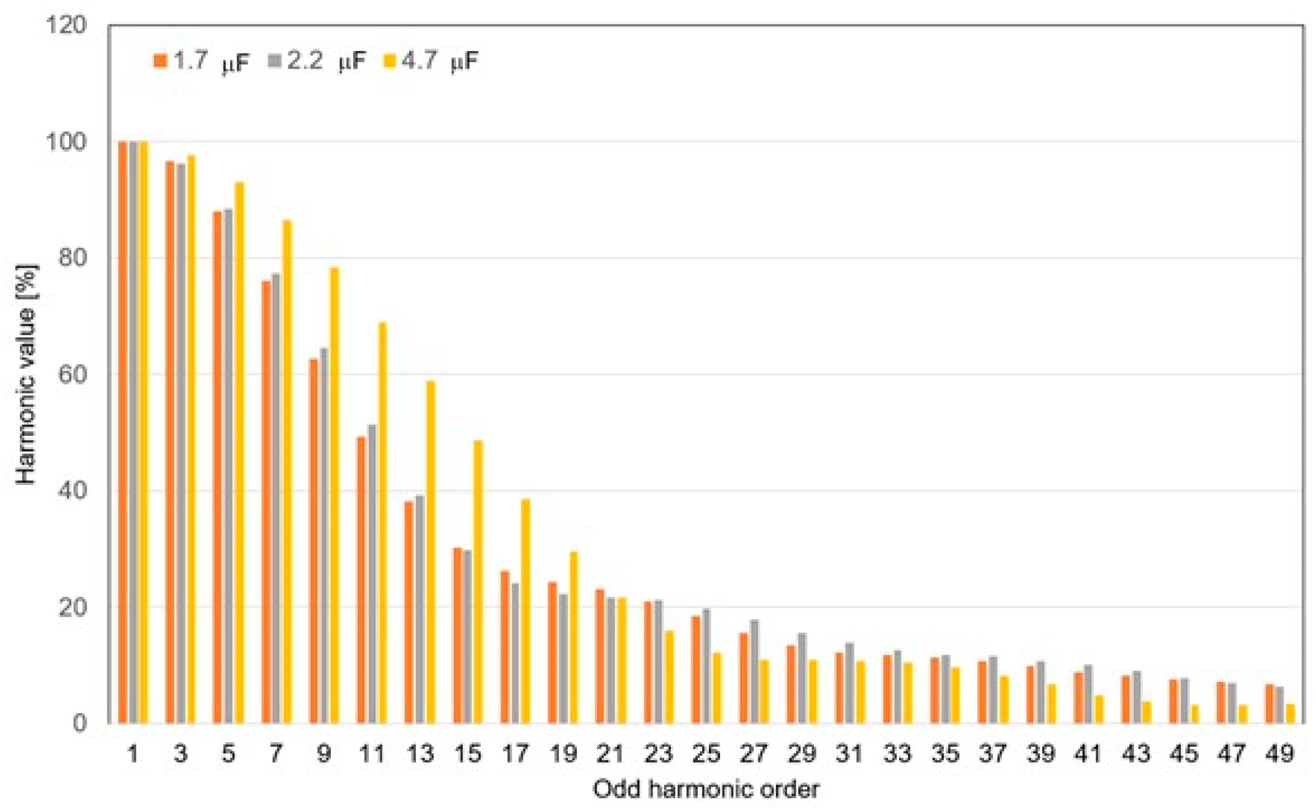
In the next step, a comparison was made of the values of the higher odd harmonics of the current generated by the LED lamp under test for the three considered cases of changes in the shape and value of the current. A summary of the harmonics is shown in Figure 32. The results obtained allow us to conclude that in the case of installing a smoothing capacitor Cf of 4.7 µF in the power supply, there was a significant increase in odd current harmonics especially the dominant ones of orders 3 to 19. It can also be concluded that the other harmonics (from orders 21 to 49) decreased. However, it should be emphasised that it is the current harmonics of the lower orders, i.e., 3, 5, 7, 9, etc., that affect the distortion of the supply voltage. The significant increase in these harmonics is due to the parameters of the current flowing through the RGB LED lamp. As can be seen from Figure 31, the current pulse is very short, the angle determining the start of the pulse rise has a value of 72°, and the value of the current in the peak is 165 mA. In summary, the use of a 4.7 µF Cf capacitor in the power supply is not recommended. Favourable results were obtained by installing a Cf capacitor of 1.7 µF in the lamp power supply. In this case, there was an increase in the duration of the current pulse, and the peak current value was 148 mA (Figure 29). This resulted in a reduction in the values of individual harmonics compared to the other analysed cases (Figure 32).
Reducing the values of individual current harmonics in the case of using a capacitor Cf = 1.7 µF is beneficial and results in a reduction in the value of current THD to 188.65%. The obtained value is the lowest compared to the other two cases, in which the capacitors Cf = 2.2 µF and Cf = 4.7 µF were used. A summary of the results is given in Table 5.
When comparing the favourable case in which a capacitor of 1.7 µF was used in the power supply with the case in which the LED lamp operated with a factory-installed capacitor of 2.2 µF, one can see an increase in the duration of the current pulse, a decrease in the value at the peak, and a decrease in THD of about 2%.

4. Conclusions

In this paper, the results of tests on the generation of harmonic currents by an RGB LED lamp that cooperates with a radio remote control have been reported. The tests were carried out in a specialised electromagnetic compatibility laboratory.
The RGB LED lamp under test is very functional, as it allows one to make changes in the value of white-light flux with a dedicated remote control. The multiple functional possibilities provided by the RGB LED lamp in the study imposed the need to conduct the research in four stages. Changes in the values of individual harmonics in the situation of changes in the value of luminous flux, changes in its colour, or during the use of built-in utility functions have been analysed. The results make it possible to determine to what extent the values of individual current harmonics change at individual stages of regulation of the value and colour of the luminous flux and during the implementation of built-in functions. The comparative analyses performed make it possible to determine in what situation the harmonic values increase and when they decrease. Analysis of the results made it possible to conclude that the duration of the current pulse drawn by the lamp is one of the factors affecting the value of individual current harmonics. Therefore, in the fourth stage of the study, changes were made in the power supply of the test lamp, changes were made in the rectifier module, in which the factory-installed rectified voltage ripple filter capacitor of 2.2 µF was replaced by a capacitor of 4.7 µF and then 1.7 µF (series connection of capacitors with values of 2.7 and 4.7 µF). The results obtained allowed us to conclude that the extension of the current pulse flowing through the RGB LED lamp causes a reduction in the values of individual dominant harmonics and thus a reduction in the value of the THD coefficient of the current. This is one of several methods of reducing the emitted higher harmonics. There are more ways to reduce individual harmonics, such as using passive LC filters before and after the rectifying bridge or PFC power factor correction. In some solutions, the Cf filter capacitor is eliminated from the power supply of the LED lamp, etc. In general, it can be concluded that all additional methods to eliminate higher harmonics involve an increase in the price of the final product, which may affect the solutions used by lamp manufacturers.
Reducing the value of higher harmonics generated by LED lamps is a very important research issue due to the widespread use of this type of device. Therefore, the research results described in this article may inspire further work in this field, e.g., determination of system conditions used in LED lamp power supplies related to the mechanism of harmonics generation, analysis of distorted current waveforms in LED lamps, and selection of appropriate filters limiting higher harmonics. In addition, the new solutions developed to limit the emission of higher harmonic currents in LED lamps must be small in size, as LED lamp manufacturers sometimes have problems fitting the entire electronic circuitry into the LED lamp stem.
It should also be noted that the tests carried out were not intended to determine the compliance of the tested RGB LED lamp with the requirements of the relevant EMC standards. The authors plan to extend the research work to conducted as well as radiated emissions, which is relevant to the generation of disturbances in the radio frequency range.

Author Contributions

Writing—original draft preparation, conceptualization, methodology, K.K. (Kazimierz Kuryło); writing—review and editing, D.K.; resources, validation, formal analysis, investigation, data creation, visualization, K.K. (Kazimierz Kuryło), W.S., D.K., K.K. (Kazimierz Kamuda), and P.J.-M. All authors have read and agreed to the published version of the manuscript.

Funding

This research paper was developed under the project financed by the Minister of Education and Science of the Republic of Poland within the “Regional Initiative of Excellence” program for the years 2019–2023. Project number 027/RID/2018/19, amount granted PLN 11,999,900. The work was partially developed by using equipment purchased in the following EU programs: POPW.01.03.00-18-012/09-00; UDA-RPPK.01.03.00-18-003/10-00.

Data Availability Statement

Data are contained within the article.

Conflicts of Interest

The authors declare no conflicts of interest. The funders had no role in the design of the study; in the collection, analyses, or interpretation of data; in the writing of the manuscript; or in the decision to publish the results.

References

  1. Sabat, W.; Klepacki, D.; Kamuda, K.; Kuryło, K. Analysis of LED Lamps’ Sensitivity to Surge Impulse. Electronics 2022, 11, 1140. [Google Scholar] [CrossRef]
  2. Sabat, W.; Klepacki, D.; Kuryło, K.; Kamuda, K. Analysis of propagation process of conductive electromagnetic disturbances in AC/DC low power converter. In Proceedings of the 21st European Microelectronics and Packaging Conference (EMPC) & Exhibition, Warsaw, Poland, 10–13 September 2017; pp. 1–5. [Google Scholar] [CrossRef]
  3. Sabat, W.; Klepacki, D.; Kurylo, K.; Kamuda, K. Mathematical Model of the Susceptibility of an Electronic Element to a Standardized Type of Electromagnetic Disturbance. Energies 2023, 16, 7022. [Google Scholar] [CrossRef]
  4. Kuryło, K.; Sabat, W.; Klepacki, D.; Kamuda, K. Comparison of Two Measurement Methods for the Emission of Radiated Disturbances Generated by LED Drivers. Energies 2022, 15, 9372. [Google Scholar] [CrossRef]
  5. Arias, M.; Vazquez, A.; Javier, S. An overview of the AC-DC and DC-DC converters for LED lighting applications. Automatika 2012, 53, 156–172. [Google Scholar] [CrossRef]
  6. Dolara, A.; Leva, S. Power Quality and Harmonic Analysis of End User Devices. Energies 2012, 5, 5453–5466. [Google Scholar] [CrossRef]
  7. Bednarek, K.; Kasprzyk, L. Suppression of higher harmonic components introduction to the networks and improvement of the conditions of electric supply of electrical equipment. Electr. Eng. Rev. 2012, 88, 236–239. [Google Scholar]
  8. Gonen, T. Electric Power Distribution System Engineering, 3rd ed.; CRC Press: Boca Raton, FL, USA, 2014. [Google Scholar]
  9. Das, J.C. Power System Harmonics and Passive Filter Designs, 1st ed.; Wiley-IEEE Press: Hoboken, NJ, USA, 2015. [Google Scholar]
  10. Hanzelka, Z. Electricity quality part 4-High harmonics of voltages and currents. Electr. Install. 2001, 12, 10–17. [Google Scholar]
  11. Zeghoudi, A.; Bendaoud, A.; Canale, L.; Tilmatine, A.; Slimani, H. Common Mode and Differential Mode Noise of AC/DC LED Driver. In Proceedings of the IEEE International Conference on Environment and Electrical Engineering and IEEE Industrial and Commercial Power Systems Europe (EEEIC/I&CPS Europe), Bari, Italy, 7–10 September 2021; pp. 1–6. [Google Scholar] [CrossRef]
  12. Zeghoudi, A.; Bendaoud, A.; Halima, S.; Benazza, B.; Houcine, M.; Canale, L. Power Impact and Electromagnetic Disturbances of different Lighting modes from Spot LED Lamp. Optik 2022, 269, 169898. [Google Scholar] [CrossRef]
  13. Bollen, M.H.J.; Rönnberg, S.K.; Larsson, E.O.A.; Wahlberg, M.; Lundmark, C.M. Harmonic emissions from installations with energy-efficient lighting. In Proceedings of the 11th International Conference on Electrical Power Quality and Utilization, Lisbon, Portugal, 17–19 October 2011; pp. 1–6. [Google Scholar] [CrossRef]
  14. Kus, V.; Pikous, J. The effects of connecting high amounts of nonlinear appliances to the supply network. In Proceedings of the 5th IEEE International Conference on Power Engineering, Energy and Electrical Drives (POWERENG), Riga, Latvia, 11–13 May 2015; pp. 201–206. [Google Scholar] [CrossRef]
  15. Putz, Ł.; Bednarek, K.; Nawrowski, R. Disturbances Generated by Lighting Systems with LED Lamps and the Reduction in Their Impacts. Appl. Sci. 2019, 9, 4894. [Google Scholar] [CrossRef]
  16. Pop, F.; Munteanu, C.; Răcăşan, A.; Păcurar, C.; Pruşu, S.; Mihai, G. Evaluation of conducted disturbances from LED lamps according to EN 55015. In Proceedings of the International Conference on Communications (COMM), Bucharest, Romania, 9–10 June 2016; pp. 509–512. [Google Scholar] [CrossRef]
  17. Karim, F.A.; Ramdhani, M.; Kurniawan, E. Low pass filter installation for reducing harmonic current emissions from LED lamps based on EMC standard. In Proceedings of the International Conference on Control, Electronics, Renewable Energy and Communications (ICCEREC), Bandung, Indonesia, 13–15 September 2016; pp. 132–135. [Google Scholar] [CrossRef]
  18. Barwar, M.K.; Sahu, L.K.; Bhatnagar, P. Reliability Analysis of PFC Multilevel Rectifier Based LED Driver Circuit. In Proceedings of the Second International Conference on Power, Control and Computing Technologies (ICPC2T), Raipur, India, 1–3 March 2022; pp. 1–5. [Google Scholar] [CrossRef]
  19. Kotny, J.L.; Duquesne, T.; Idir, N. EMI Filter design using high frequency models of the passive components. In Proceedings of the IEEE 15th Workshop on Signal Propagation on Interconnects (SPI), Naples, Italy, 8–11 May 2011; pp. 143–146. [Google Scholar] [CrossRef]
  20. Wantuch, A.; Olesiak, M. Effect of LED Lighting on Selected Quality Parameters of Electricity. Sensors 2023, 23, 1582. [Google Scholar] [CrossRef] [PubMed]
  21. Michalec, Ł.; Jasiński, M.; Sikorski, T.; Leonowicz, Z.; Jasiński, Ł.; Suresh, V. Impact of Harmonic Currents of Nonlinear Loads on Power Quality of a Low Voltage Network–Review and Case Study. Energies 2021, 14, 3665. [Google Scholar] [CrossRef]
  22. Key, T.S.; Lai, J.-S. Costs and benefits of harmonic current reduction for switch-mode power supplies in a commercial office building. IEEE Trans. Ind. Appl. 1996, 32, 1017–1025. [Google Scholar] [CrossRef]
  23. Arrillaga, J.; Watson, N.R. Power System Harmonics, 2nd ed.; John Wiley &Sons: Hoboken, NJ, USA, 2004. [Google Scholar]
  24. O’Connell, K. Heating Effects through Harmonic Distortion on Electric Cables in the Built Environment. Ph.D. Thesis, Dublin Institute of Technology, Dublin, Ireland, 23 July 2013. Available online: https://arrow.tudublin.ie/cgi/viewcontent.cgi?article=1058&context=engdoc (accessed on 15 July 2023).
  25. Modernization of Lighting at the Best Western Old Town Hotel in Krakow. Available online: https://greenie-world.com/en/implementations/22245/ (accessed on 22 July 2023).
  26. The Rapid Transition to Energy Efficient Lighting: An Integrated Policy Approach. Available online: https://www.unep.org/resources/report/rapid-transition-energy-efficient-lighting-integrated-policy-approach (accessed on 15 July 2023).
  27. Abdalaal, R.M.; Man Ho, C.N. Characterization of Commercial LED Lamps for Power Quality Studies. IEEE Can. J. Electr. Comput. Eng. 2021, 44, 94–104. [Google Scholar] [CrossRef]
  28. Sakar, S.; Rönnberg, S. Interferences in AC-DC LED drivers due to Harmonic Voltage Emission. In Proceedings of the CIRED 2021—The 26th International Conference and Exhibition on Electricity Distribution, Online Conference, Geneva, Switzerland, 20–23 September 2021; pp. 860–864. [Google Scholar] [CrossRef]
  29. Chęciński, J.; Filus, Z. Analysis of supply parameters of single- and double-string LED lamps with integrated AC direct capacitorless drivers. Bull. Pol. Acad. Sci. Tech. Sci. 2020, 68, 819–827. [Google Scholar] [CrossRef]
  30. Phase-Cut Dimmable High Side Buck LED Driver with High Power Factor. Available online: https://pdf1.alldatasheet.com/datasheet-pdf/view/957390/RICHTEK/RT8402.html (accessed on 15 July 2023).
  31. FL77904 Phase-Cut Dimmable Compact LED Direct AC Driver. Available online: https://www.onsemi.com/download/data-sheet/pdf/fl77904-d.pdf (accessed on 15 July 2023).
  32. Molina, J.; Mesas, J.; Mesbahi, N.; Sainz, L. LED Lamp Modelling for Harmonic Studies in Distribution Systems. IET Gener. Transm. Distrib. 2017, 11, 1063–1071. [Google Scholar] [CrossRef]
  33. Uddin, S.; Sharef, H.; Krause, O.; Mohamed, A.; Hannan, M.A.; Islam, N.N. Impact of large-scale installation of LED lamps in a distribution system. Turk. J. Electr. Eng. Comput. Sci. 2015, 23, 1769–1780. [Google Scholar] [CrossRef]
  34. Ramljak, I.; Tokic, A. Harmonic emission of LED lighting. AIMS Energy 2020, 8, 1–26. [Google Scholar] [CrossRef]
  35. Lamar, D.G.; Arias, M.; Fernandez, A.; Villarejo, J.A.; Sebastian, J. Active Input Current Shaper without an Electrolytic Capacitor for Retrofit Lamps Applications. IEEE Trans. Power Electron. 2017, 32, 3908–3919. [Google Scholar] [CrossRef]
  36. Cheng, C.-A.; Cheng, H.-L.; Chang, C.-H.; Chang, E.-C.; Kuo, Z.-Y.; Lin, C.-K.; Hou, S.-H. An AC-DC LED Integrated Streetlight Driver with Power Factor Correction and Soft-Switching Functions. Sustainability 2023, 15, 10579. [Google Scholar] [CrossRef]
  37. Yau, Y.-T.; Hwu, K.-I.; Liu, K.-J. AC–DC Flyback Dimmable LED Driver with Low-Frequency Current Ripple Reduced and Power Dissipation in BJT Linearly Proportional to LED Current. Energies 2020, 13, 4270. [Google Scholar] [CrossRef]
  38. Di Mauro, S.; Musumeci, S.; Raciti, A.; Vasta, G. Analysis of the current harmonics injected into the power grid by dimmable LED lamps. In Proceedings of the AEIT International Annual Conference (AEIT), Capri, Italy, 5–7 October 2016; pp. 1–6. [Google Scholar] [CrossRef]
Figure 1. Oscillograms of distorted voltage and current measured in a multi-family building.
Electronics 13 00531 g001
Figure 2. Current harmonics in electrical power system of typical commercial building [22].
Electronics 13 00531 g002
Figure 3. Decomposition of a time-domain distorted waveform into a first (50 Hz) and a fifth harmonic (250 Hz).
Electronics 13 00531 g003
Figure 4. Spectrum of first end fifth harmonic distorted signal illustrated in Figure 3.
Electronics 13 00531 g004
Figure 5. Example of illumination of a traffic route in a large department store in Rzeszów in Poland (own photograph).
Electronics 13 00531 g005
Figure 6. Example of architectural illumination—Rzeszów Old Town in Poland (own photograph).
Electronics 13 00531 g006
Figure 7. A simple LED power supply with a Graetz rectifier bridge and a capacitor to smooth the rectified voltage ripple Cf and a current limiting resistor R [29] (a), passive power supply with LC input filter and Valley-Fill circuit (b) [27], active power supply with EMI filter and buck converter (c) [27]. Arrow indicates LED diode which emmit the light.
Electronics 13 00531 g007
Figure 8. LED power supply with a specialised RT8402 electronic chip for power factor correction [30]. Arrow indicates LED diode which emmit the light.
Electronics 13 00531 g008
Figure 9. LED power supply with specialised electronic chip FL 77904, which allows one to regulate the luminous flux of the LED lamp [31]. Arrow indicates LED diode which emmit the light.
Electronics 13 00531 g009
Figure 10. Schematic of the diode bridge rectifier with smoothing capacitor (a) and waveforms of voltage and current drawn by the diode bridge rectifier with smoothing capacitor (b) [24].
Electronics 13 00531 g010
Figure 11. The odd harmonic spectrum of the current drawn by a full-wave rectifier presented in Figure 10.
Electronics 13 00531 g011
Figure 12. An illustration of the RGB LED lamp under test and the dedicated remote control.
Electronics 13 00531 g012
Figure 13. Test stand for testing LED lamps: 1—programmable voltage source; 2—PC with installed specialised software to control the power source; 3—power quality analyser; 4—luminaire with the LED lamp under test; 5—PC with installed specialised software working with the power quality analyser.
Electronics 13 00531 g013
Figure 14. Illustrative wiring diagram of the test stand.
Electronics 13 00531 g014
Figure 15. Measured values of the rms current flowing through the LED lamp at each adjustment stage (on adjustment stages 2, 3, and 4, current oscillations are visible).
Electronics 13 00531 g015
Figure 16. Oscillations of current flowing through the RGB LED lamp at the third stage of white-light flux control.
Electronics 13 00531 g016
Figure 17. Oscillograms of the current flowing through the RGB LED lamp in the 5th control stage (pulse duration t = 2.44 ms, and its amplitude im = 250 mA).
Electronics 13 00531 g017
Figure 18. Oscillograms of current flowing through the RGB LED lamp in the 3rd control stage (pulse duration t = 1.46 ms, and its amplitude im = 180 mA).
Electronics 13 00531 g018
Figure 19. Spectrum of odd harmonic currents generated by RGB LED lamp in the 5th, 3rd, and 1st control stage.
Electronics 13 00531 g019
Figure 20. THD values of the current for the individual adjustment steps (5th, 3rd, and 1st) of the white light flux.
Electronics 13 00531 g020
Figure 21. Measured values of the rms current consumed by the LED lamp at each light colour adjustment step: W—white light; R—red light; G—green light; B—blue light.
Electronics 13 00531 g021
Figure 22. Oscillograms of current flowing through an RGB LED lamp that emits red (R) light (pulse duration t = 1.17 ms, and its amplitude im = 101 mA).
Electronics 13 00531 g022
Figure 23. Spectrum of odd harmonic currents generated by RGB LED for light colours R, G, and B.
Electronics 13 00531 g023
Figure 24. Comparison of the 17th harmonic current values for the analysed three light colours—R, G, and B.
Electronics 13 00531 g024
Figure 25. Measured values of the rms current drawn by the LED lamp implementing the built-in Flash, Strobe, and Smooth functions.
Electronics 13 00531 g025
Figure 26. Spectrum of odd harmonic currents generated by an LED lamp implementing an embedded Flash function.
Electronics 13 00531 g026
Figure 27. Spectrum of odd harmonic currents generated by an LED lamp implementing embedded RGB, Flash, Strobe, and Smooth functions.
Electronics 13 00531 g027
Figure 28. Block diagram of the RGB LED lamp under test. The figure shows the capacitors that were replaced with 1.7 and then 4.7 capacitors µF.
Electronics 13 00531 g028
Figure 29. The shape of the current flowing through the RGB LED lamp and its angular position relative to the voltage of the filter capacitor Cf = 1.7 µF.
Electronics 13 00531 g029
Figure 30. The shape of the current flowing through the RGB LED lamp and its angular position with respect to the voltage for the filter capacitor Cf = 2.2 µF.
Electronics 13 00531 g030
Figure 31. The shape of the current flowing through the RGB LED lamp and its angular position with respect to the voltage for the filter capacitor Cf = 4.7 µF.
Electronics 13 00531 g031
Figure 32. Spectrum of odd harmonic currents generated by the LED lamp for three cases of changing the value of the smoothing capacitor Cf (filtering voltage ripple).
Electronics 13 00531 g032
Table 1. Summary of typical test frequency ranges implemented in the field of EMC testing.
Higher HarmonicsConducted InterferenceRadiated Interference
50 Hz to 2.5 kHz9 kHz to 150 kHz
150 kHz to 30 MHz
30 MHz to 1 GHz
Table 2. Summary of analysed parameter values for selected degrees of control of the luminous flux value of white light emitted by the RGB LED lamp.
Adjustment LevelsAnalysed Parameters
Odd Harmonic Current Value [%]THDI [%]i [mA]t [ms]
357911
589.7972.1351.2532.7122.48140.69250.002.44
396.3188.3877.4564.5451.41190.75180.001.46
199.0996.8794.0391.0586.58289.7851.000.56
Table 3. Summary of values of selected odd harmonics of current for the individual colours of light emitted by the lamp: red (R), green (G), and blue (B).
Analysed Light ColoursAnalysed Parameters
Odd Harmonic Current Value [%]THDI [%]i [mA]t [ms]
357911
R99.3295.0589.4582.1273.75234.73101.001.17
G97.2295.2492.9988.3784.51272.8563.000.88
B102.23100.4397.3693.1489.03297.9453.000.87
Table 4. Summary of the values of the odd harmonics of current selected for points A and B, when the LED lamp was operated with the Smooth function enabled.
PointAnalysed Parameters
Odd Harmonic Current Value [%]THDI [%]RMS I [mA]
3579111315
A97.3791.2583.4373.5563.0151.6841.01209.0326.00
B99.5797.9294.2490.1384.9980.0573.63275.3211.00
Table 5. Summary of values of selected odd harmonics of current, THD, value, and duration of current pulse for three cases of changes in the value of capacitor Cf in the power supply of the lamp under test.
Capacitor ValueAnalysed Parameters
Odd Harmonic Current Value [%]THDI [%]i [mA]t [ms]
357911
1.7 μF96.6088.0376.1662.6449.28188.65148.001.76
2.2 μF96.3188.3877.4564.5451.41190.75180.001.46
4.7 μF97.6393.0886.5678.3568.95215.46165.001.26
Disclaimer/Publisher’s Note: The statements, opinions and data contained in all publications are solely those of the individual author(s) and contributor(s) and not of MDPI and/or the editor(s). MDPI and/or the editor(s) disclaim responsibility for any injury to people or property resulting from any ideas, methods, instructions or products referred to in the content.